1
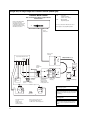
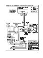
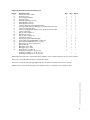
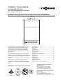
Installation / Service Manual
for Vitogas 050, RS Series
Gas-fired, atmospheric cast iron boiler
550 to 1050 MBH / 161 to 308 kW
IMPORTANT: READ AND SAVE THESE INSTRUCTIONS FOR FUTURE REFERENCE
These instructions cover the installation, operation and
servicing of the Viessmann Vitogas 50, RS series of cast-iron
sectional atmospheric gas-fired hot water boilers. These
instructions must be read thoroughly prior to installation.
These instructions must be saved and made available to
service technicians when required. Install boiler according to
these instructions.
The installation of this unit shall be in accordance with local
codes or, in the absence of local codes, use CSA-B149.1 or .2
Installation Codes for Gas Burning Appliances for Canada. For
U.S. installations use ANSI Z223.1. Always use latest editions
of codes.
Where required by the authority having jurisdiction, the
installation must conform to the Standard for Controls and
Safety Devices for Automatically Fired Boilers, ANSI/ASME
CSD-1.
These instructions must be placed in an envelope and affixed
to the boiler.
®
5167 456 v1.2 03/2007
Contents:
Page:
Technical Data ..........................................................................3
Boiler Features .........................................................................4
Installation.................................................................................4
Gas Connections ......................................................................7
Water Connections ...................................................................8
Vent Connections ...................................................................10
Accessories ............................................................................10
Start-up and Operating Instructions ........................................11
Maintenance ...........................................................................13
Troubleshooting ......................................................................17
Piping Layouts ........................................................................18
Wiring Diagrams .....................................................................22
Installation Checklist ...............................................................24
Replacement Parts List...........................................................25
Assembly of cast-iron block using draw tool ...........................30
Viessmann Manufacturing Company Inc.
750 McMurray Road
Waterloo, Ontario • N2V 2G5 • Canada
Tel. (519) 885-6300 • Fax (519) 885-0887
www.viessmann.ca • [email protected]
Viessmann Manufacturing Company (U.S.) Inc.
45 Access Road
Warwick, RI • 02886 • U.S.A.
Tel.: (401) 732-0667 Fax: (401) 732-0590
www.viessmann-us.com • [email protected]
This “Attention” symbol is located beside all
important safety recommendations. Please follow
the instructions in detail to avoid property damage,
severe personal injury, or loss of life.
Warning: If the information in this manual is not
followed exactly, a fire or explosion may result
causing property damage, personal injury, or
loss of life.
Do not store or use gasoline or other flammable liquids
in the vicinity of this or any other appliance.
WHAT TO DO IF YOU SMELL GAS
• Do not try to light any appliances.
• Do not touch any electrical switches, do not use any
phone in your building.
• Immediately call your gas supplier from a neighbor’s
phone. Follow the gas supplier’s instructions.
• If you cannot reach your gas supplier, call the fire
department.
Installation and service must be performed by a qualified
installer, service agency or the gas supplier.
Warning:
The installation, adjustment, service, and maintenance
of this boiler must be done by a licensed professional
service technician who is qualified and experienced in
the installation, service, and maintenance of commercial
gas-fired hot water boilers. There are no user
serviceable parts on the boiler, burner, or control.
Failure to heed this warning can cause property damage,
severe personal injury, or loss of life.
Warning:
Before each heating season begins, have the following
service and maintenance done by a professional service
technician:
1)
Boiler heat exchanger inspected and cleaned.
2)
Vent system inspected for deterioration, leaks,
corrosion, proper draft, and proper operation. Check
vent system for compliance with local and national
code requirements. Repair or replace as required.
3)
Burner checked and if necessary adjusted for
proper combustion and operation. Check for
adequate supply of fresh outside combustion and
ventilation air.
Neglecting to perform necessary maintenance can cause
unsafe operation.
Warning:
Never operate the boiler without an installed venting
system which safely vents all products of combustion to
the outdoors. The vent system must comply with all
applicable local and/or national codes.
Improper, incomplete, obstructed, or deteriorated vent
systems can present a serious risk of flue gases leaking
into living space which could cause carbon monoxide
poisoning.
Warning:
Warning:
Improper installation, adjustment, service, or
maintenance can cause flue products to flow into living
space. Flue products contain poisonous carbon
monoxide gas which can cause nausea or asphyxiation
resulting in severe personal injury or loss of life.
Warning:
Should overheating occur or the gas supply fail to shut
off, do not disconnect the electrical supply to the pump.
Instead, shut off the gas supply at a location external to
the appliance.
Do not use this boiler if any part has been under water.
Immediately call a qualified service technician to inspect
the boiler and to replace any part of the control system
and any gas control which has been under water.
2
Never operate the boiler without an adequate supply of
fresh combustion air. This boiler needs fresh air for safe
operation and must be installed so there are provisions
for adequate combustion and ventilation air. All
combustion and ventilation air must be supplied from
the outside. Failure to heed this warning can cause
severe personal injury or loss of life.
Warning:
Shut off all electrical power and turn off gas or oil supply
to boiler before performing any service or maintenance
on the boiler, burner, or control. Failure to follow this
warning could result in electrical shock, serious
personal injury or loss of life.
Do not store chemicals containing chlorine or other
corrosive materials near the boiler, such as bleach,
cleaning solvents, detergents, acids, hair spray, spray
cans, paint thinners, paint, water softener salt,
refrigerants.
PC
BWR
BD
Total width
153⁄4"/400mm
Depth
Total depth
Legend
BD
Boiler Drain
BWR Boiler Water Return
BWS Boiler Water Supply
FGC Flue Gas Collar
GC1 Main Gas Connection
GC2 Pilot Gas Connection
521⁄2"/1335mm
41⁄2"/
110mm
19"/481 mm
GC1
501⁄2"/1284mm
BWS
GC2
PRV
321⁄2"/830mm
Height
Height 1
Height 2
FGC
PC
Pilot Cover Plate
PRV Pressure Relief Valve Connection
Technical Data
Boiler Model
CSA input
Model No.
full load *1
partial load *2
CSA output
full load *1
partial load *2
RS-8
RS-11
RS-14
MBH
kW
MBH
kW
550
161
372
109
800
234
541
158
1050
308
710
208
MBH
kW
MBH
kW
468
137
316
93
680
199
460
135
893
261
604
177
Combustion efficiency
%
85.0
85.0
85.0
Heat exchanger
surface area
ft2
m2
99.47
9.2
140.63
13.1
181.79
16.9
Cast-iron sections
8
11
14
Burners
7
10
13
Manifold pressure
Natural gas
full load
partial load *3
Propane gas
full load
partial load *3
"w.c.
"w.c.
"w.c.
"w.c.
3.5
1.3
10
3.5
1.3
10
3.5
1.3
10
Man. gas supply pressure *4
"w.c.
14
14
14
343⁄4
883
361⁄4
921
533⁄4
1366
343⁄4
883
491⁄2
1255
533⁄4
1366
343⁄4
883
691⁄4
1582
533⁄4
1366
Dimensions
Depth
Width
Height
inches
mm
inches
mm
inches
mm
Boiler Model
Model No.
RS-8
RS-11
RS-14
inches
mm
inches
mm
47
1195
361⁄4
921
47
1195
491⁄2
1255
47
1195
621⁄4
1582
Total height
Height 1 (control unit in
position for operation)
Height 2 (control unit in
position for servicing)
inches
mm
inches
mm
601⁄4
1531
731⁄2
1867
601⁄4
1531
731⁄2
1867
601⁄4
1531
731⁄2
1867
Weight, boiler with insulation,
burners and packaging
lbs
kg
1280
582
1709
777
2138
972
Boiler water content
USG
ltr
20
77
28
106
35
134
Max. operating pressure
psig
kPa
60
414
60
414
60
414
2
2
2
⁄4
3⁄4
3⁄4
1
1
1 ⁄4
11⁄4
10
250
12
300
14
350
Overall dimensions
Total depth
Total width
Boiler connections
Boiler supply and return
Boiler drain
Ø"
(male thread)
Ø"
Gas supply connection
Ø
(male thread)
Vent pipe collar
inches
3
Combustion results are based on a heating system supply temperature of 167 oF / 75 oC, return 140 oF / 60 oC
For two-stage boilers only
Parial load manifold pressure is factory preset. Any attempt to readjust in the field will render boiler warranty null and void.
If the gas supply pressure is higher than the maximum permissible value, a separate field supplied gas regulator must be
installed upstream of the boiler gas train.
For for information regarding other Viessmann System Technology componentry, please reference documentation of the
respective product.
*1
*2
*3
*4
3
1.0
Shipping of boiler
The boiler comes with water connections on the right
hand side in the standard configuration. If required, the
connections can be made on the left side by reversing
the gas inlet pipe and reversing the flange connections
for the water connections. See section 2.2 and piping
layouts Figs. 11, 23, 24 and 25.
The boiler is shipped in two pieces. An assembled castiron heat exchanger is shipped on a wooden pallet. The
second piece is a crate containing the jacket, draft
hood, gas train, and manifold. Boiler requires final field
assembly.
Max. boiler operating pressure 60 psi (414 kPa).
Max. boiler temperature 248°F (120°C).
Any damages caused by operation in excess of the
above mentioned temperatures and pressure are not
the responsibility of Viessmann Manufacturing
Company Inc.
Cast iron
heat exchanger
List of parts shipped
Rear
For a complete list of parts refer to Replacement Parts
List on page 25.
Front
2.0
Wooden pallet
Installation
Important:
231⁄2˝
(600mm)
Note that the sheet metal enclosure is designed in such
a way that the enclosure can be installed after all water
piping, pipe insulation, draft hood and venting has been
completed. Install sheet metal enclosure last to
minimize the chance of damage to the enclosure. Final
gas piping is done after installing sheet metal enclosure.
Fig. 1
Assembled cast-iron heat exchanger
Before boiler is connected to a piping/heating system
which has been in service (boiler is a replacement
boiler), piping system should be flushed thoroughly with
water in order to remove sludge, rust, debris, or other
contaminants, especially in large piping systems such
as old gravity systems. Failure to remove contaminants
can lead to boiler failure.
25˝
RS-8
RS-11
RS-14
561⁄2˝
561⁄2˝
661⁄2˝
Note: The RS boiler is for use in closed loop hot water
forced circulation systems only. Do not use in
steam applications.
Crate is 42˝ deep for all sizes
Fig. 2
Crate containing draft hood and jacket
2.1
Both pieces (Fig. 1 and Fig. 2) will fit through a standard
32˝ doorway. Casting may be ordered split in two or
more sections to facilitate handling. Refer to separate
heat exchanger assembly instructions.
Assembly of split cast-iron heat exchanger requires the
use of a Viessmann draw tool, which must be specified
at time of ordering. See page 30 for use of draw tool.
1.1
4
Boiler features
The Vitogas 50, RS boiler series includes the following
features and standard equipment:
– Cast-Iron sections of wet base design, fully
assembled
– Boiler ID coding card
– Intermittent pilot ignition system
– Stainless steel burner tubes
– Horizontal to vertical draft diverter
– Accessory pack including 50 psi pressure relief valve,
air vent and pressure gauge
Installation of supply and return flanges
Prior to placing the boiler in its installed position, ensure
that the supply and return flanges are on the correct side
of the boiler. The standard configuration has the supply,
return connections on the right side. To reverse the
water connections see section 2.2. Also see Fig. 23 on
page 18.
2.2
Installation with piping on left side
To install boiler with water piping on the left side instead
of the right, the following must be done:
a)
b)
Remove the supply flange and gasket, and the
opposite flange threaded 1˝ NPT (i.e. pressure
relief valve fitting).
Remove the return flange, gasket, 60mm studs,
and the opposite flange threaded 3⁄4˝ NPT (i.e. drain
cock fitting). NOTE that the return flange is fitted
with a water distribution tube. Holes are drilled to
distribute water vertically into the casting and
horizontally into the wet base casting legs. When
Remove the 5-point well from the right tapping and
the plug or well from the left. Install the well into the
left tapping, and plug the right hand tapping. Use a
thread sealer such as hemp (included in accessory
kit) and pipe thread sealant when installing these
fittings.
36˝
(914mm)
c)
18˝
(457mm)
switching from right to left, rotate the tube 90°
clockwise to align the holes with the water
passages in the casting (see Fig. 3). Remount the
flanges and gaskets.
Draft
hood
Note: Supply and return pipes must be installed on
same side of boiler.
Boiler
jacket
Boiler
casting
20˝
(508mm)
Fig. 4
Minimum clearances to combustibles – side view
Vertical outlet
Boiler
casting
8˝
(203mm)
8˝
(203mm)
6˝
(152mm)
Gasket
6˝
(152mm)
Horizontal outlet
Water distribution pipe
Gasket
Return flange
Fig. 3
Water distribution tube – boiler return
2.3
Boiler
casting
Location
The boiler must be installed in an indoor space not
subject to freezing temperatures. The boiler should be
located near a floor drain. The boiler must be installed
on a solid level foundation capable of supporting the
boiler and piping filled with water.
The boiler casting is shipped fully assembled on a
wooden skid. To remove the boiler from the skid, lift it
off using a hoist of sufficient capacity, or use a fork lift
from the side. Refer to Technical Data, for boiler weight.
Observe maximum allowable floor weight when
positioning boiler.
Never lift boiler using the draw rods. Place the boiler so
that the following clearances to combustible materials
are maintained.
Top:
18˝
(457 mm)
Back:
6˝
(152 mm)
Side 1:
6˝
(152 mm)
Side 2:
6˝
(152 mm)
Floor: Non-combustible
Boiler jacket
Fig. 5
Minimum clearances to combustibles – top view
Additionally, the following service clearances should be
observed:
Front:
48˝
(1220 mm)
Side:
24˝
(610 mm)
(with supply, return, gas connections and pilot)
Note that these clearances are from the assembled
boiler enclosure. See Fig. 4 for clearances from bare
casting. If a concrete pad is required, refer to Technical
Data, for boiler base dimensions. Boiler must not be
installed on carpeting.
2.4
Combustion air supply
This boiler needs fresh air for safe operation and must
be installed so there are provisions for adequate
combustion and ventilation air. All combustion air must
come from the outside.
5
Provisions for combustion and ventilation air must be
made in accordance with section 5.3, Air for
Combustion and Ventilation, of the National Fuel Gas
Code, ANSI Z223.1, or applicable provisions of the local
codes. In Canada follow CAN/CGA-B149.1 or .2
Installation Codes. Always use latest edition of codes.
The following guideline is taken from the
CAN/CGA-B149 Code:
2.4.1 Assembly (see Figs. 6, 7, 11, 23, 26)
These instructions cover the assembly of the standard
boiler with right hand water and left hand gas
connections. Prior to installing the jacket assembly,
ensure that the boiler well(s), plug, and flanges are
tight. Refer to sections 8.2 and 8.4 for burner assembly
instructions.
2.4.2 Draft hood
Combustion air supply shall have a cross sectional area
of not less than 100 in2 plus 1 in2 for each 14,000 Btu/h
in excess of 400,000 Btu/h. This opening(s) shall be
either located at, or ducted to, a point neither more than
18 inches nor less than 6 inches above the floor level.
In addition to the combustion air supply, a ventilation air
supply connection shall be made at the highest practical
point communicating with outdoors with a minimum
area of 10% of the combustion supply opening area.
The draft hood is made up from four separate panels,
refer to Fig. 6
a) Place top panel upside down on floor.
b) Attach the side panels to the top panel using the
self-tapping screws (12 x 1⁄2˝). An 8 mm or 5⁄16˝
socket is required.
c) Attach the front panel using the self-tapping
screws.
Note: On RS-14 models only, install the downdraft
deflector inside the draft hood using 2 Phillips screws.
ATTENTION
The boiler must not be located in areas or rooms where
chemicals are stored, or aggressive vapors (for
example: bleach, hair spray, methyl chloride, carbon
tetrachloride or perchloroethylene) or high dust levels or
humidity levels are present. Heat exchanger corrosion
might occur and reduce the lifetime of the boiler
significantly. If above criteria are not properly observed
and boiler damage results, any warranty on the
complete boiler and related components will be null and
void.
Ensure that there are no visible gaps where the panels
are fastened together.
Mounting draft hood
The draft hood is mounted to the boiler using four M8 x
30 bolts and nuts. Refer to Fig. 7 for further details.
2.4.3 Boiler jacket assembly (see Fig. 26)
Install pilot burner (section 8.4) and wiring prior to
assembling jacket.
5
6
1
2
3
4
Fig. 6
Draft hood – exploded view
6
1
2
3
4
Top panel
Right side panel
Left side panel
Front panel. Removable
for inspection and cleaning
5 Self-tapping screw – 12 x 1⁄2˝
6 Downdraft deflector (RS-14 only)
2.4.4 Gas controls (see Figs. 9, 11, 22, 23, 25)
Draft hood assembly
M8 x 30
bolts
Boiler casting
Detail
Fig. 7
Mounting draft hood
Refer to Fig. 9, Gas controls, and Wiring diagram.
a) Connect gas train to the burner manifold using the
union provided. Align gas train with manifold and
tighten union.
b) Connect pilot gas tubing to the fitting downstream
of the pilot gas valve. The tubing is connected
using a compression fitting. Install pilot burner on
same side as manifold gas train connection (see
Figs. 23, 25).
c) Connect the gas supply pipe upstream of the “tee”
fitting, using the union provided. Install a drip leg
and shut-off valve in the gas supply pipe outside
the boiler.
d) Connect low voltage wiring as shown in wiring
diagram. Ensure that ground connection between
pilot burner and ignition module is made.
e) Install upper front cover panel on four push pins.
Insert the temperature sensors from the Vitotronic
control into the 5-point well located in the upper
right hand corner of the mid panel. (The insulation
in this opening may require cutting.) Be careful not
to kink the capillary tubes! Refer to Fig. 10.
f) Connect the #41 plug from the Vitotronic control to
the #41 plug from the ignition system or to #41 plug
of either a vent damper or a power venter (see
wiring diagrams).
2.4.5 Gas connections
Refer to Fig. 26 for jacket assembly.
a) Assemble four frame rails (items 52, 53, 54) around
casting base, with overhang toward front. Fasten
with four M6 nuts.
b) Assemble side panels. Press upper (items 57, 58)
and lower (items 81, 82) side panels together by
inserting push studs into retainers. Press the front
side panel (item 65) to the upper and lower panel
assembly and fasten with Phillips screws (two per
side).
c) Place the assembled side panels on the side
frame. To ease assembly, tape the side panels to
the draft hood to hold them vertical.
d) Attach rear panel (item 63) to side panels using
eight 7 x 1⁄2˝ self-tapping Phillips screws. Angled
fold must be at top and pointing inward. Remove
tape applied in step c).
e) Position lower mid panel (item 67) so that the lower
fold sits on the pins on the burner manifold. Fasten
to side panels using two 7 x 1⁄2˝ Phillips screws.
f) Position upper mid panel (item 62) and fasten to
lower mid panel and side panels using four
7 x 1⁄2˝ Phillips screws.
g) Position the top cover (item 69) and press push
studs into retaining clips.
h) Press lower front panel (item 66) onto side panels.
i) Place blank cover over the unused opening on the
lower side panel on the side opposite the pilot
burner. Fasten using four 7 x 1⁄2˝ Phillips screws.
j) Mount the Vitotronic control housing on the middle
of the top front panel using 4 x 1⁄2˝ Phillips sheet
metal screws. The Vitotronic control can be
mounted on the housing using the three black
riveted screws shipped with the Vitotronic controls.
Connect gas to main burner via the opening for the gas
pipe in the left or right side panel (see Figs. 11, 23).
Install a capped drip leg and a manual gas shut-off
valve outside the boiler. Size gas supply to boiler
according to local requirements. Under no
circumstances shall the gas supply pipe be of smaller
diameter than the boiler’s gas pipe.
Minimum natural gas supply pressure: 7.0˝ w.c. and 11˝
w.c. for LP (measure at gas connection to boiler).
Maximum gas supply pressure for all gases: 14.0˝ w.c.
All factory-assembled gas connections have been leak
tested. A leak test must be repeated during the initial
operation of the boiler by the installer. Use an approved
liquid spray solution to check for leaks at all fittings and
unions. Never use an open flame to check for leaks.
Check gas input by clocking gas meter after all water and
electrical connections have been made, and boiler has
been filled with water. When checking input using a gas
meter, ensure that all other gas-fired equipment is shut off.
Safe lighting and other performance criteria were met
with the gas manifold and control assembly provided on
the boiler when the boiler underwent tests specified in
ANSI Z21.13 boiler standard.
7
Gas
supply
A
B
C
F
Test
valve
D
Manual
Redundant
gas shut- automatic
off valve gas valve
Combination
regulator and
automatic gas
valve
Adjustable high limit sensor bulb
Manual reset high limit sensor bulb
1
⁄4˝ flexible
tubing
Leak test
tap
E
1
⁄4˝ aluminum
or copper
tubing
Thermometer
1
⁄2˝
Manifold pressure
test port
Attach to mid panel with sheet
metal screw
Install cable clamp to secure high
limit capillaries in well
Cut at 45°
angle
Jar or glass
with water
Fig. 8
Gas valve leak test
Fig. 10
5-point boiler well
9. Slowly open the test valve (F).
10. When the rate of bubbles coming through the water
stabilizes, count the number of bubbles appearing
during a 10 second period. Each bubble appearing
during a 10 second period represents a flow rate of
approximately 0.001 ft3/h (27 cm3/h).
Pilot gas pressure (5˝) regulator RV-10
Pilot gas valve ITT
Pilot gas pressure test port 1⁄8˝ NPT
Reducing
elbow
Pilot manual
shut-off valve
Reducing
bushing
Tee
Automatic gas
valve
Main gas valve
and regulator
Pressure test port
1
⁄8˝ NPT
90° street elbow
Union
Inlet
pressure
test port
1
⁄8˝ NPT
Manual gas
shut-off valve
To meet all U.S. requirements, leakage must not
exceed the values given below.
Manual test
firing valve
Union
Gas burner manifold
Gas valve leakage test
Maximum inlet pressure for all gases 14˝ w.c.
This is a test for checking the tightness of closure of the
gas safety shut-off valves. It should be performed by
qualified personnel during the initial start-up of a burner
system, or whenever the valve is replaced. It is
recommended that this test also be included in
scheduled inspection and maintenance procedures. For
a periodic inspection test, follow steps 1, 3, 4, 5, 8, 9,
10, 12, 13, 16 and 17.
8
1. De-energize the control system to ensure that there
is no power to the safety shut-off valves (B) and
(C), shown in Fig. 8.
2. Close the upstream manual gas valve (A).
3. Make sure the manual test valve (F) is closed in the
leak test tap assembly (D).
4. Remove the leak test tap plug and connect the test
apparatus to the leak tap (D).
5. Close the downstream manual gas valve (E).
6. Open the upstream manual gas valve (A).
7. Run the safety shut-off valves (B) and (C) to their
fully open positions (through the safety system);
then immediately de-energize the system to close
the valves.
8. Immerse a 1⁄4˝ tube vertically 1⁄2˝ (12.7mm) into a jar
of water.
Allowable
leakage
No. of bubbles
per 10 sec.
1, 11⁄4
353 cm3/h
13
Following the test:
11. Close the upstream manual gas valve (A).
12. Close the test valve (F), remove the test apparatus,
and replace the leak test tap plug (D).
13. Open the upstream manual gas valve (A) and
energize the safety shut-off valves (B) and (C).
14. Test with soap bubbles to ensure that there is no
leak at the test tap (D).
15. De-energize the safety shut-off valves (B) and (C).
16. Open the downstream manual gas valve (E).
17. Restore the system to normal operation.
Fig. 9
Gas control assembly
3.0
Gas valve
size (in.)
4.0
Water connections (see Figs. 11, 15, 23, 24, 25)
The 2˝ NPT supply and return water connections must
be on the same side of the boiler (right side is
standard). Use isolation valves for service purposes.
The length of 2˝ pipe should be limited to the distance
from the boiler to the main headers which will usually be
larger than 2˝ diameter pipe. This distance should be
kept as short as possible. Larger diameter pipe can be
used to connect the boiler to the main supply and return
headers. Use standard friction loss methods for
calculating pipe sizes.
4.1
Low water cut-off
An approved low water cut-off device must be supplied
and installed by the mechanical contractor (see Fig. 11).
Do not install shut-off valve between low water cut-off
and boiler.
4.3
Flow direction must
be as shown
Gas
pipe
Return
Vitotronic control
40
Power
120V
60 Hz
2˝
Low water
cut-off
probe or
float type
2˝
75
90
60
3.6
Lubricated
plug valve
85
flF
120
55
100
70
0.4
80
flC
2.0
Treatment for boiler feed water should be considered in
areas of known problems, such as high mineral content
and hardness. In areas where freezing might occur, an
antifreeze may be added to the system water to protect
the system. Please adhere to the specifications given
by the antifreeze manufacturer. Never use silicate
based automotive antifreeze.
Supply
Sensing well
for aquastat
capillaries
flC
Please observe that an antifreeze/water mixture may
require a backflow preventer within the automatic water
feed and influence components such as diaphragm
expansion tanks, radiation, etc. A 40% antifreeze
content will give freeze-up protection to approximately
-10°F (-23.3°C). Do not use antifreeze other than
specifically made for hot water heating systems. System
also may contain components which might be
negatively affected by antifreeze. Check total system
frequently when filled with antifreeze.
Min. 2˝ above
2˝ supply pipe
centerline
6˝
150
Mount relief
valve, air vent
and pressure
gauge to
tapping on left
hand side
Pilot burner
mounting side
Drip leg
with cap
Mount drain valve
to lower tapping
Fig. 11
Standard Vitogas 50, RS boiler piping connections
RS boiler with right hand water piping, left hand gas piping
(Boiler shown with access panel removed)
4.2
Initial system fill
A pressure reducing valve (or “fill” valve) is required to
reduce the incoming water pressure. The total of the fill
pressure, pump head, and any small pressure rise from
thermal expansion of the water must be less than the
boiler pressure relief valve setting. An expansion tank
must be connected to the system close to the suction
side of the circulating pump to prevent pressure
increase resulting from thermal expansion of the system
water.
Pump selection and pump aquastat
Fig. 12 shows the head loss through the boiler at
various flow rates for the Vitogas 50 boilers.
7.0
28
6.5
26
6.0
24
5.5
22
5.0
20
4.5
18
4.0
16
3.5
in W.C.
kPa
HEAD LOSS
The minimum return water temperature is 120°F
(48.8°C). The maximum temperature rise between
return and supply is 68°F (37.7°C).
14
RS
11
RS
8
RS
14
3.0
12
2.5
10
2.0
8
1.5
6
1.0
4
0.5
2
0
0
0
0
Fig. 12
Head loss through boiler
10
38
20
76
30
114
40
152
50
190
60
228
70
266
80
304
90
342
100
380
USG/min
ltr./min
FLOW
9
5.0
Boiler venting
Negative pressure Test
In Canada follow CSA–B149.1 or .2, in USA follow
National Fuel Gas Code ANSI Z223.1. Always use
latest edition of national codes.
c)
Insofar as is practical, close all building doors and
windows and all doors between the space in which
the appliances remaining connected to the
common venting system are located and other
spaces of the building. Turn on any exhaust fans,
such as range hoods and bathroom exhausts, so
they will operate at maximum speed. Do not
operate a summer exhaust fan. Close fireplace
dampers.
The boiler should be located as close to the chimney as
possible. The vent connection must be made in the
shortest possible way with minimum elbows.
d)
Place in operation the appliance being inspected.
Follow the lighting instructions. Adjust thermostat
so appliance will operate continuously.
When the vertical pipe becomes the chimney itself, the
weight must not be supported by the horizontal to
vertical draft hood on the boiler.
e)
Test for spillage at the draft hood relief opening
after 5 minutes of main burner operation. Use an
approved smoke test.
Avoid long horizontal runs of vent pipe. Horizontal runs
must be supported by appropriate means to prevent
sagging. Horizontal runs should have not less than 1⁄4˝
rise per ft. from the boiler to the vent terminal.
f)
After it has been determined that each appliance
remaining connected to the common venting
system properly vents when tested as outlined
above, return doors, windows, exhaust fans,
fireplace dampers and any other gas burning
appliance to their previous condition of use.
g)
Any improper operation of the common venting
system should be corrected so the installation
conforms with the National Fuel Gas Code, ANSI
Z223.1- latest edition. When resizing, any portion of
the common venting system should be resized to
approach the minimum size as determined using
the appropriate tables in Appendix G in the
National Fuel Gas Code, ANSI Z223.1- latest
edition.
Vitogas 50, RS boilers are Category I boilers. Category
I does not apply when boiler is side wall vented.
The mounted boiler draft hood must not be altered or
modified in the field.
Metal strapping must be used to support horizontal runs
every 4 ft.
Use approved vent material only. For venting purposes,
a B-0, B-1 or B-11⁄2 vent may be used. Use C vent for
vent connectors.
With this boiler installation, it is recommended to install
an approved liner within a masonry or unlined chimney.
Observe and follow local rules and regulations.
The vent connector of this boiler must not be connected
into any portion of mechanical draft systems operating
under positive pressure.
5.2
A side wall power vent system can be ordered. This
package includes the appropriate power venter and
vent terminal for each boiler model, as well as
installation instructions. Consult Viessmann technical
sales representative for ordering.
Based upon proper chimney and breeching size, the
boiler may be vented into a chimney/breeching with a
direct-fired (atmospheric-fired) gas water heater.
Observe national codes, local rules and regulations.
5.1
Removal of existing boiler
The vent system must terminate so that proper
clearances are maintained as cited in the National Fuel
Gas Code, ANSI Z223.1, Section 7, and as detailed in
the Side Wall Vent System Installation Instructions.
Observe and follow these instructions carefully.
When an existing boiler is removed from a common
venting system, the common venting is likely to be too
large for proper venting of the appliances remaining
connected to it.
6.0
At the time of removal of an existing boiler, the following
steps shall be followed with each appliance remaining
connected to the common venting system placed in
operation, while the other appliances remaining connected
to the common venting system are not in operation.
a) Seal any unused openings in the common venting
system.
10
Visually inspect the venting system for proper size
and horizontal pitch and determine there is no
blockage or restriction, leakage, corrosion, or any
other deficiency which could cause an unsafe
condition.
Accessories
Pressure relief valve, pressure gauge, drain cock and
fittings are packed separately. Refer to Fig. 13. Install
relief valve and pressure gauge into upper flange with
1˝ tapping. Install drain valve into lower flange with 3⁄4˝
tapping.
6.1
b)
Side wall vent system
Installation of pressure relief valve (see Fig. 13)
Pressure relief valve must be installed. Do not install
shut-off valve between pressure relief valve and boiler.
After checking for gas leakage according to sections
2.4.4, 2.4.5 and 3.0, ensure pilot pressure is between 5˝
and 6˝ w.c. for natural gas and between 8˝ and 10˝ w.c.
for LP with pilot burner operating.
Pressure relief valve
Air vent
Attach manometer to test port downstream of pilot
valve. Close main burner test firing valve so that only
pilot burner operates. Pilot pressure is factory adjusted
to 5.0˝ w.c. with a supply pressure of 7.0˝ w.c. for
natural gas. Adjust pilot pressure if necessary to
between 5.0˝ and 6.0˝ w.c. and between 8˝ and 10˝ w.c.
for LP. The ionization signal has to be greater than
1 µA D.C. (typical 3-5 µA D.C.) Re-attach pressure port
and leak test.
Pressure gauge
faces towards
boiler front
Flange
After checking pilot pressure, check manifold pressure
with manometer to ensure it is 3.5˝ w.c. Do no operate
the burner at pressures higher than 3.5˝ w.c. Test port
at centre of gas manifold may be used. To open, turn
screw in fitting counterclockwise two turns. To close,
turn screw clockwise until it seats. Leak test pressure
port.
Front of boiler
Fig. 13
Boiler accessories
The standard pressure relief valve is a Watts 1˝ Model
174A set at 50 psi with a relief capacity of 1,400,000
Btu/h. Maximum allowable working pressure of boiler is
60 psig.
For 2-stage RS boilers, the first stage pressure is
factory preset to 1.3˝ w.c. Do not attempt to readjust it.
Any attempt to readjust this pressure will render the
warranty null and void.
Optional relief valve is 1˝ Watts 174A set at 60 psi with
a relief capacity of 1,621,000 Btu/h.
7.2
Optional relief valve is 1˝ Watts 174A set at 30 psi with
a relief capacity of 958,000 Btu/h.
Boiler electrical requirements are 120V, 60 Hz, less
than 12A. Pumps must be powered by separate power
supply.
A discharge pipe the same diameter as the pressure
relief valve discharge opening must be rigidly installed
directly onto the pressure relief valve. The discharge
should extend to the floor drain and end approximately
6˝ above drain. Do not install a shut-off valve in
discharge piping. Do not pipe discharge outdoors. Refer
to Fig. 13.
See wiring diagram in rear of manual and wiring label
on boiler. Viessmann reserves the right to substitute
electrical components as necessary. The boiler wiring
label diagram takes precedence.
All wiring must be properly grounded! Before
attempting to wire the unit, disconnect power supply at
main service panel first. Dedicated ground wire must
be run from boiler to service panel.
Never cap or plug relief valve opening or discharge
pipe. The discharge pipe must be arranged so as to
prevent scalding of attendants. Follow instructions
supplied with pressure relief valve.
All electrical wiring is to be done in accordance with
the latest edition of the National Electrical Code ANSI
/NFPA 70. In Canada use CSA C22.1 Part 1 and/or
local codes.
If pressure relief valve is discharging frequently locate
source of problem and correct. Significant amounts of
make-up water will cause mineral deposits in boiler
which may lead to boiler failure. This type of failure is
not covered under warranty.
7.0
Ensure that boiler is filled with water prior to start-up.
7.1
Caution:
Start-up and operating instructions
Do not attempt to start the boiler if you smell gas. If you
smell gas, open windows, do not touch electrical
switches, extinguish any open flame, close all gas
valves immediately. See page 14 for detailed lighting
instructions.
Pilot and manifold pressure check
Gas supply pressure must not exceed 14˝ w.c. for all
gases.
Boiler wiring
Label all wires prior to disconnection when servicing
controls. Wiring errors can cause improper and
dangerous operation. Verify proper operation after
servicing.
7.3
Testing – gas pipe
The boiler and its individual shut-off valve must be
disconnected from the gas supply piping system during
any pressure testing of that system at test pressures in
excess of 14˝ w.c. (3.5 kPa).
The boiler must be isolated from the gas supply piping
system by closing its individual manual shut-off valve
during any pressure testing of the gas supply
11
piping system at test pressures equal to or less than 14˝
w.c. (3.5 kPa).
Cooling season starts: Close valve V1 and open
valve V2.
Heating season starts: Close valve V2 and open
valve V1.
A metal tag should be attached to these valves as to
purpose.
Unions and manifold have been factory-tested. Leak
test must be repeated during initial trial operation of
burner by mechanical contractor.
Note:
In the above system, the circulating pump must be
operated from a separate on/off switch – not from the
pump aquastat on the boiler!
Never check for gas leaks with an open flame. Use
approved liquid spray solution for bubble test. Follow
Fig. 14 whenever gas valve is replaced.
Proper piping practice
7.5
Main burner
Proper piping practice
2 imperfect Control
threads
Use moderate amount of dope
Proper flame:
Upper main flame cone with light
orange coloring, sharply defined
individual flames.
Underfired:
Lazy-burning main flame cone,
mushy flame appearance throughout,
smaller flame sizes than in Fig. 16.
Overfired:
Increased burner noise, higher flame
sizes than Fig. 16.
Pipe
Thread pipe correct length, leave 2 end threads bare.
Fig. 14
Gas piping into gas valve
7.4
Support piping by proper suspension method. Piping
must not rest on or be supported by boiler.
7.6
Boiler piping in heating/cooling application
Proper flame:
Pilot burner
The boiler, when used in connection with a refrigeration
system, must be installed so the chilled medium is
piped in parallel to the boiler with appropriate valves to
prevent the chilled medium from entering the boiler
(Fig. 15).
Upper main flame cone with light orange
coloring, sharply defined individual flame.
Main flame cone
7˝
Light blue
Heating/
cooling unit
Inner flame cone
Heating/
cooling unit
Blue
CP
FC
V
Heating/
cooling unit
FC
V2
Burner
PRV
V
Water
chiller
V
FC AFV V
V1
Fig. 16
Front view – single burner
Fig. 15
Boiler piping in a heating/cooling application
The boiler piping system of a hot water heating boiler
connected to heating coils located in air handling units
where they may be exposed to refrigerated air
circulation must be equipped with flow control valves or
other automatic means to prevent gravity circulation of
the boiler water during the cooling cycle.
6˝
(150mm)
Ionization
electrode
Pilot
burner
Orange outer
flame cone
Blue inner
flame cone
Ignition
electrode
Check installation instructions of chiller manufacturer
carefully for additional requirements.
Main burner
12
Fig. 17
Side view – pilot burner
Underfired:
Lazy-burning main flame cone, mushy flame
appearance throughout, smaller flame size
than in Fig. 17.
Overfired:
Increased pilot burner noise, long inner and
outer flame cone towards main burner.
7.7
Periodically:
•
•
•
7.8
Note: If the operating limit is set at the maximum setting
194°F (90°C), the pump must run after burner shutdown to prevent a boiler temperature rise tripping the
manual reset high limit. This can be avoided by setting
the pump aquastat 18°F (10°C) below the operating
limit setting.
8.0
WARNING: Always switch off and disconnect electricity
supply and close the manual gas shut-off valve before
carrying out service work or replacement of failed
components.
Inspect low water cut-offs, including flushing of float
types (if used).
Inspect flow switch (if used).
Inspect main burner flame and pilot burner
Service agency – annually:
8.1
Boiler servicing – heat exchanger cleaning
8.2
7.9
General
Full maintenance should be undertaken not less than once
per year. After servicing work has been completed or any
component replaced, the boiler must be fully tested.
The heat exchanger should be cleaned once a year as
outlined in section 8.3.
Before heating season starts, boiler/burner should be
serviced by a qualified service agency.
Maintenance
Main burner removal (see Figs. 16, 18, 19)
Lighting instructions – (see page 14)
electronic ignition – natural gas
Main burner tubes are removed individually from the
manifold. They are located at the back by a pin, and at
the manifold by the gas orifice and an offset pin, and
retained by a Phillips screw.
a)
Follow steps outlined on page 14
a)
Ensure manual gas shut-off valve is in the closed
position and turn off all electric power to the boiler.
b)
Ignition will occur at pilot burner. When pilot is
ignited, ionization electrode will prove flame, and
control will open main gas valve. Pilot flame will
then ignite main burner.
b)
Remove the front door of the casing and the lower
front panel by pulling forward.
c)
Remove the Phillips screw M5 x 8 securing each
burner tube to the burner manifold and remove the
burners.
d)
Using a stiff brush, not a wire brush, brush the
burners to dislodge any accumulated deposits.
Inspect the burners to ensure that they are clean.
e)
Examine the orifices and if damaged or
deteriorated, replace with new ones of the correct
size and marking (see Table 1 below). If necessary,
clean the orifices. Do not broach with wire.
f)
Re-assemble the orifices and burners in the
reverse order to that above. To install burner tubes,
insert the burner tube facing up from under the gas
manifold, and slide along guide on bottom edge of
boiler casting. When burner support pin engages in
locating hole at the back of the casting, align burner
tube with orifice, and pull tube back over the orifice
and locating pin on manifold; fasten with Phillips
screw. If the heat exchanger is to be cleaned,
replace burner tubes only after cleaning is completed.
Trial for pilot ignition is 15 seconds. If pilot flame is not
established in 15 seconds, control will lock out.
If ignition control locks out then restart by turning power
off, waiting 5 minutes, then turning power back on
again. This can be done by turning the 120V power
supply off, or the on/off switch on the boiler Vitotronic
control. The remote operating control can also be used
to reset the ignition control. Ignition will occur according
to the above procedure.
The Honeywell ignition S8600B control does not require
manual reset on flame failure. The S8600B is standard
equipment.
If it is required to have manual reset on pilot flame failure,
the boiler must be ordered with the RA890F flame
safeguard control (not shown in this manual). Specify
RA890F at the time of ordering for pricing and delivery.
7.10
Vitotronic control
For combination space heating and domestic hot water
consult Viessmann sales representative for control
options and piping diagrams.
If boiler water temperature exceeds 248°F (120°C), the
fixed high limit will be tripped. To reset, use a pointed
object, such as a pencil tip, to push in green button until
an audible click is heard.
Table 1: GAS ORIFICES
Altitude above
sea level
Natural Gas
ømm
L.P. Gas
ømm
0 – 2000 ft.
2000 – 4500 ft.
2000 – 7000 ft.
4.30
4.10
4.10
2.50
2.30
2.30
13
Lighting instructions – intermittent pilot ignition system:
FOR YOUR SAFETY READ BEFORE OPERATING
WARNING: If you do not follow these instructions exactly, a fire or explosion
may result causing property damage, personal injury or loss of life.
Boiler and piping system must be filled with water and purged of all air before
operating boiler. All installation requirements and safety inspections must be
completed before operating boiler.
A.
This appliance is equipped with an ignition device
which automatically lights the pilot. Do not try to light
the pilot by hand.
B.
BEFORE OPERATING smell all around the boiler area
for gas. Be sure to smell next to the floor because
some gas is heavier than air and will settle on the
floor.
●
If you cannot reach your gas supplier, call the fire
department.
C.
Use only your hand to turn lever operated manual gas
shut-off valves. If the lever handle will not turn by
hand, call a qualified service technician or the gas
supplier.
D.
Do not use this appliance if any part has been under
water. Immediately call a qualified service technician
to inspect the appliance and to replace any part of the
control system and any gas control which has been
under water.
WHAT TO DO IF YOU SMELL GAS
● Do not try to light any appliance.
● Do not touch any electrical switch; do not use any
phone in your building.
● Immediately call your gas supplier from a
neighbor’s phone. Follow the gas supplier’s
instructions.
OPERATING INSTRUCTIONS
1.
STOP! Read the safety information above on this
page.
2.
Set the thermostat or other operating control to the
lowest setting.
3.
Turn off all electric power to the boiler.
4.
This appliance is equipped with an ignition device
which automatically lights the pilot. Do not try to light
the pilot by hand.
Manual gas shut-off valve
5.
Remove control access panel.
6.
Turn all manual gas shut-off valves to closed
position.
7.
Wait five (5) minutes to clear out any gas. Then smell
for gas, including near the floor. If you smell gas,
STOP! Follow “B” in the safety information above. If
you don’t smell gas, go to the next step.
8.
Turn all manual gas shut-off valves to the open
position.
9.
Replace control access panel.
10. Turn on all electric power to the boiler.
Open
11. Set thermostat or other operating control to desired
setting.
12. If the boiler will not operate, follow the instructions
“To Turn Off Gas To Boiler” and call your service
technician or gas supplier.
Closed
TO TURN OFF GAS TO BOILER
1.
Set the thermostat or other operating control to
lowest setting.
2.
Turn off all electric power to the boiler if service is to
be performed.
14
3.
Remove control access panel.
4.
Turn all manual gas shut-off valves to closed
position.
5.
Replace control access panel.
Diagonal passes
with brush
Boiler casting
Gas orifice
Locating hole
Support pin
Burner
manifold
Burner
tube
Guide
Fig. 18
Installing burner tubes – side view
Boiler casting
Second passes
with brush
Fig. 20
Cleaning heat exchanger
Burner screw
Fig. 19
Burner tube installed
8.3
d)
Remove the front inspection and cleaning cover to
get access to the heat exchanger.
e)
Remove self tapping screw from lower side rear
panel which is located through rear panel.
f)
Remove lower side rear panel by using the two
finger holes and pulling away from the upper side
rear panel and lifting away from casing frame.
g)
Remove the heat exchanger lower clean-out door
by removing the four brass retaining nuts and lifting
away.
h)
Remove clean-out door gasket to expose flueways.
Remove flue gas baffles (one per flueway).
i)
Repeat e) – h) for opposite side.
Heat exchanger cleaning (see Fig. 20)
While the main burner tubes are removed from the
appliance, the flueway should be cleaned.
a)
Remove the main front panel and the top cover by
pulling upwards to expose the draft hood.
Disconnect wiring to Vitotronic control and remove
sensors from boiler well. Remove the upper front
panel with the Vitotronic control. Be careful not to
kink any capillary tubes or strain any wiring.
b)
Remove the four screws retaining the upper mid
panel and remove the upper mid panel.
c)
Remove all screws fixing the front inspection and
cleaning cover to the draft hood.
Clean flue gas passageway as per Fig. 20 using the
clean-out brush supplied.
8.4
Pilot burner assembly removal (see Figs. 17, 21, 22)
The pilot assembly may be removed either while the
main burners are in the boiler or after the main burners
have been removed, as previously described in
Section 8.2.
15
Ignition electrode
Ionization
electrode
Pilot
burner
44±2
9.5±2
Ionization
electrode
Ignition
electrode
(always on
bottom)
2-3mm
16mm
Ground screw
Fig. 21
Pilot burner assembly – electrode settings
a)
b)
c)
8.5
To remove the pilot assembly, release the ground
wire at the ground screw on the pilot burner, detach
the lead at the ionization probe and pull the lead at
the spark electrode. Disconnect pilot tube at the
pilot burner connection and remove the three nuts
M6 securing the mounting plate assembly to the
combustion chamber cover plate.
Standard gas train
requires pilot to be
mounted on right
side. See Fig. 11 and
Fig. 23A.
Fig. 22
Pilot burner installed
8.6
Burner damage
Do not allow drywall dust to accumulate in burners.
Assemble boiler after all drywall work has been
completed.
8.7
Freezing damage
Inspect pilot burner, ionization probe and spark
electrode, making sure that they are in a sound and
clean condition. In particular check that ignition
electrode is clean and undamaged, and that the
spark gap is 2-3 mm, ionization and ignition leads
are not broken, chafed or burnt. Clean the pilot
orifice, do not broach out with wire (see Fig. 21).
Boiler and system must be protected from damage
caused by expansion of freezing water.
Reassemble the pilot and refit onto the combustion
chamber cover plate in reverse order to that above
(see Fig. 22). Pilot burner should be removed when
cleaning heat exchanger to prevent debris from
blocking pilot orifice.
If system is subject to freezing temperatures and is not
filled with antifreeze for protection, the system including
the boiler must be drained of water. Valve before
automatic feed valve (if installed) must be closed; any
other valves, air vents and drain valves must stay open.
Water damage
Any electrical part or any gas control that has been under
water cannot be reused but must be replaced. Mechanical
parts that have been under water must be inspected for
suitability by a boiler technician prior to reuse.
16
Note: Pilot is shown
on left side.
Protect boiler and system from freezing by using a
glycol mixture as described in section 4.3. Propylene
glycol mixtures with a corrosion inhibitor are frequently
used. Consult a reputable water treatment specialist.
9.0
Troubleshooting – spark ignition system
TROUBLE
CAUSE
REMEDY
Pilot burner will
not light
No call for heat
Check that contacts on thermostat
or operating control are closed.
Boiler temperature
too high
Allow boiler to cool and ensure
that limit controls are reset.
No power
Check for 120 VAC power to transformer.
Check for 24 VAC power from transformer
secondary side.
Boiler not switched on
Switch boiler “on” from control panel.
Low water cut-off
switch open (if equipped)
Check that boiler and system are
filled with water.
Pilot gas valve not
opening
Check wiring to pilot valve. Replace
gas valve if necessary.
No gas
Check that all valves are open.
Bleed air from line if necessary.
Check orifice in pilot burner for
blockage.
No spark
Check electrode gap of igniter.
Check connections on high tension
cable to igniter.
Ignition module faulty. Replace.
Poor ionization
Check condition of ionization
electrode and electrode gap. Repair
or replace. Check pilot gas pressure.
Poor ground
Check all ground connections back
to main power panel.
Gas valve fails to
open
Faulty ignition control module
Check wiring to main gas valve.
Replace main gas valve.
Replace ignition control module.
Pilot fails to light;
boiler locks out
Pilot lights
briefly, then locks
out
Main burners fail
to light
Caution:
Condensation can occur in the heat exchanger if boiler is
operated for long periods of time with return water
temperatures less than 120°F (49°C). Significant flue gas
condensation in the boiler will cause corrosion and premature
failure. This type of failure is not covered under warranty.
For boilers connected to large water content systems, such as
a previous gravity system with large free-standing radiators, a
bypass line from supply pipe to the return pipe can be used. A
minimum return water temperature of 120°F (49°C) can be
achieved by diverting some of the flow of heated supply water
into the flow of return water to the boiler. Valves suitable for
balancing, such as globe valves, shall be used and a
thermometer installed in the return line.
For boilers connected to underfloor heating systems utilizing
plastic tubing with an oxygen diffusion barrier, a 4-way mixing
valve with external control or other suitable alternative must be
installed to prevent condensation and keep boiler return water
a minimum of 120°F (49°C).
Technical sales representative can be contacted to help
resolve doubts and technical questions regarding boiler
installation.
In order to assume minimum boiler water temperature
protection, the respective space heating pump must be
connected and controlled by the boiler control (refer to the
corresponding Vitotronic boiler control manual). Pumps
exceeding a rating of 120V/3A need a separate field supplied
motor starter/contactor.
17
10.0 Piping layouts
Single boiler installation – piping arrangements
Fig. A
RS boiler with right hand water piping – left hand gas piping
Sensing well
for aquastat
capillaries
Gas
pipe
Return
Vitotronic control
2˝
Note: Gas train connection to manifold must be on the same side
as pilot assembly
Supply
Power
supply
120V
60 Hz
2˝
Double flange for return water
distribution pipe
Pilot assembly
Capillaries
Low water
cut-off,
probe or
float type
Mount relief valve,
air vent and pressure
gauge to tapping on
left hand side
Return water
distribution pipe
on this side
Pilot
burner
mounting
side
Fig. B
RS boiler with all piping and pilot on left hand side
Supply
Power
supply
120V
60 Hz
2˝
Double flange for return water
distribution pipe
Pilot assembly
Fig. C
RS boiler with all piping and pilot on right hand side
Return
2˝
Gas
pipe
Return
Vitotronic control
Sensing well
for aquastat
capillaries
Vitotronic control
Power
supply
120V
60 Hz
2˝
Sensing well
for aquastat
capillaries
Capillaries
Capillaries
Low water
cut-off,
probe or
float type
Pilot
burner
mounting
side
2˝
Gas
pipe
Supply
Low water
cut-off,
probe or
float type
Return water
distribution pipe
on this side
Mount relief valve, air
vent and pressure
gauge to tapping on
right hand side
Mount relief valve, air
vent and pressure
gauge to tapping on
left hand side
Return water
distribution
pipe on this
side
Pilot
burner
mounting
side
Figures A, B, C show piping arrangements for single boiler installation. RS boiler comes with water distribution pipe
and 2˝ threaded connections on right hand side as standard equipment. Refer to Section 2.2 for details on changing
water piping from right side to left side. If necessary, return water distribution pipe and 5-point capillary well, may
have to be moved.
Fig. 23
18
Multiple boiler installation – layouts
4´ 8˝
(1590mm)
S
S
R
R
R
RS-50
RS-50
RS-50
7´ 9˝
(2370mm)
S
S
R
S
RS-50
RS-50
S
R
12´ 4˝
(3760mm)
4´
(1220mm)
19´ 7˝
(5970mm)
S
2´
(610
mm)
R
RS-50
RS-50
7´ 9˝
(2370mm)
R
4´
(1220mm)
3´ 103⁄4˝
(1190mm)
11´ 9˝
(3580mm)
R
RS-50
S
Front to front lay-out
RS-50
S
R
Back to back lay-out
RS-50
S
R
2´
(610
mm)
12´ 4˝
(3760mm)
L-shape lay-out
2
(6 ´
mm10
)
S
S
RS-50
RS-50
R
R
2´
(610mm)
12´ 4˝
(3760mm)
Fig. 24
Lay-outs Vitogas RS-50 gas boilers – top view dimensions in imperial and metric
19
20
B
A
L.W.C.O.
5´ 21⁄2˝
(1588mm)
L.W.C.O.
Pilot
12´ 5˝ (3785mm)
2´ 0˝
(610mm)
Pilot
19´ 71⁄2˝ (5982mm)
L.W.C.O.
L.W.C.O.
Pilot
Pilot
L.W.C.O.
Pilot
Note: Minimum distance between
boilers is 2´ 0˝ when pilot is
between boilers.
Two Vitogas RS-50
right hand side
standard configuration
21
Pilot
Pilot
10´ 11˝ (3527mm)
6˝ (150mm)
L.W.C.O.
L.W.C.O.
L.W.C.O.
Pilot
L.W.C.O.
26´ 10˝ (8179mm)
Pilot
23´ 10˝ (7264mm)
24˝ (610mm)
Pilot
L.W.C.O.
Fig. 25
Lay-outs of Vitogas RS-50 gas boilers – front elevation. Boilers shown with front access panel removed
(Dimensions in imperial and metric)
D
C
L.W.C.O.
L.W.C.O.
Pilot
Pilot
Left hand side configurations have to
be specified at time of ordering.
Note: For layout D, pressure relief
valve, air vent and pressure gauge
have to be mounted on supply
piping.
Two left hand side configuration
Two standard right hand side
configuration
Pilot
L.W.C.O.
Vitogas 050, RS single stage with Vitotronic control (Natural gas)
Vitotronic Boiler Control
FHL
– Safety limit
manual reset fixed
(fixed at 120°C, 248°F)
AHL
– Operating limit
adjustable aquastat
Refer to internal wiring diagram supplied with the
Vitotronic Contol
Refer to wiring label affixed
to boiler access panel,
Viessmann reserves the right
to substitute components or
wiring methods. Boiler wiring
label takes precedence.
Do not operate burner without boiler control
Never bypass safety high limit aquastats
To #41
Connection
Boiler 7-pole
#41 plug
15 sec
lockout
MV
T
H
GND 24V
BRN GND 24V W
PV
MV PV
S
E
N
S
E
7-pole
#41 plug
Honeywell S8600B ignition control
S
P
A
R
K
53 plug
5-pole
L1
Class II
Transformer
40 VA
Adaptor harness
(only for use with damper)
53 plug
T1 T2
Blk
S3
Yel
B4
Blk
Grn
ITT S311
pilot
gas valve
Ionization
electrode
Landis & Gyr
QSZ1 pilot
pilot burner
Boiler 7-pole
#41 plug
Motor
Viessmann vent damper
(optional)
Org
PV
PV
PV/ MV
MV
Factory wired
junction box
Do not connect
additional 120V
to this junction box
Ignition
electrode
Org
Blk
7-pole
#41 plug
N
120 VAC
24 VAC
Yel
If vent damper not installed, connect two boiler
7-pole #41 plugs together.
PV/MV
Blk
MV
Gas flow
Blk
Caution: Label all wires prior to disconnection when
servicing controls. Wiring errors can cause improper
and dangerous operation. Verify proper operation
after servicing.
Warning! Disconnect power before
servicing boiler
Redundant Honeywell
gas valve
V8943A valve has
“PV/MV” and “PV”
terminal designations
22
Main Honeywell automatic gas valve
and regulator V8943B valve has
“PV/MV” and “PV” terminal designations
If any of the original wire as supplied with the
appliance must be replaced, it must be replaced
with 105°C rated or its equivalent. Minimum size
16 AWG.
Vitogas 050, RS 2-stage with Vitotronic control (Natural Gas)
Refer to internal wiring diagram supplied with
the Vitotronic control
To # 191
connection
To # 41
connection
2-stage
module
Boiler 7-pole
#41 plug
Class II
transformer
40 VA
leo
p7
gu
lp
1
4
#
5-pole
leo
-p7
gu
lp
1
4
#
Factory wired
Boiler 7-pole
junction box
#41 plug
Do not connect
additional 120V
to this junction box
Operating control
pl # 4
ug 9 -p
0 ol
e
Ionization
electrode
Landis & Cyr
QSZ1 Pilot
pilot burner
Ignition
electrode
Adaptor harness
(only for use with damper)
53 plug
53 plug
Motor
Viessmann vent damper
(optional)
Do not operate buner without
boiler control
Never bypass safety
high limit aquastats
Honeywell S8600B
ignition control
15 Sec
lockout
If vent damper not installed, connect
two boiler 7-pole #41 plugs together
Caution: Label all wires prior to disconnection
when servicing controls. Wiring errors can
cause improper and dangerous operation.
Verify proper operation after servicing.
Warning! Disconnect power before
servicing boiler
If any of the original wire as supplied with the
appliance must be replaced, it must be replaced with 105 ºC rated or its equivalent.
Minimum size 16AWG.
23
11.0
Checklist for proper installation
Before and after installation, use the following checklist to ensure proper installation. Improper installation could create a
hazard, resulting in damage, severe personal injury, or loss of life. The correct answer is “yes” to all of the following
questions.
a)
Is the flow direction correct?
Water flows in at bottom connection and out at top 2˝ connection?
❒
Yes
❒
No
b)
Are both the supply and return on the same side of the boiler?
❒
Yes
❒
No
c)
Is the return water distribution pipe (double flange connection) used as the return connection?
❒
Yes
❒
No
d)
Is the pilot on the same side of the boiler as the nipple used for the gas train connection?
❒
Yes
❒
No
Warning: Failure to correctly install the pilot burner will cause dangerous flame roll-out from
the main burners. The worst flame roll-out will occur with propane gas. Flame rollout can cause property damage or severe personal injury.
e)
Is the 5-point well with control capillaries in the sensing tapping nearest the supply connection?
❒
Yes
❒
No
f)
Is there a low water cut-off installed?
❒
Yes
❒
No
g)
Is the gas supply pressure at the boiler gas train between 14 and 7 ˝w.c.?
❒
Yes
❒
No
h)
Is the manifold pressure 3.5 ˝w.c. for natural gas operation with the pilot
and main burners operating?
❒
Yes
❒
No
i)
Is the pilot pressure for natural gas operation between 5 and 6 ˝w.c. with pilot running?
❒
Yes
❒
No
j)
If the RS boiler has been installed in an older piping system, has it been flushed out to ensure
debris, scale, rust and sludge will not settle in boiler?
❒
Yes
❒
No
k)
Are all pressure measurement taps installed and tightened?
❒
Yes
❒
No
l)
Are all main burners installed with ports facing up?
❒
Yes
❒
No
Caution
This boiler is not for use in systems where water is constantly
or frequently replenished. Minerals such as calcium in makeup water can deposit on heat exchanger causing overheating,
and eventually the boiler will leak. This type of failure is not
covered by warranty. Water must not be drained from system
for use by cleaning personnel. Do not draw water from boiler
for any purpose.
Caution
The boiler warranty does not cover leaks resulting from
corrosion caused by the use of underfloor plastic tubing
without an oxygen diffusion barrier. Such systems must have
the non-oxygen diffusion barrier tubing separated from the
boiler with a heat exchanger. Viessmann recommends the use
of underfloor plastic tubing with an oxygen diffusion barrier.
24
Note:
A minimum of 2˝ clearance from non-insulated hot water pipes
to combustible construction must be maintained. In cases
where the pipes are insulated with pipe insulation of
appropriate and sufficient thickness and insulation values, the
above clearance may be reduced to 0˝.
Caution:
For underfloor heating applications, an additional immersion or
strap-on aquastat must be installed in the low temperature
underfloor loop (ahead of the mixing valve) to de-energize the
pump and/or boiler in the event of overheating. Too high a
water temperature can cause damage to concrete slabs.
Fig. 26
25
Vitogas 050, RS Commercial atmospheric gas-fired cast-iron boiler
Atola-RS Parts List
Pos.
1
2
3
3
3
4
5
5
5
6a
6b
6c
7
8
9
10
11
12
13
14
15
16
17
18
19
20
21
22
23
24
25a
25b
25c
26
27
28
29a
29b
30
31
32a
32b
32c
33a
33b
34a
34b
34c
35a
35b
35c
36
37
38
39
40a
40b
40c
41
42
42
42
26
Qty
1
2
4
7
10
1
14
20
26
2
2
2
4
4
8
2
2
8
6
1
1
10
2
2
2
12
5
1
1
Description and Model
Left hand end section
Intermediate section with drilling 3⁄4˝ NPSC
Intermediate section
Intermediate section
Intermediate section
Right hand end section
Push nipple 21⁄2˝
Push nipple 21⁄2˝
Push nipple 21⁄2˝
Tie-rod M14x842
Tie-rod M14x1175
Tie-rod M14x1508
Plain washer Ø 15x28
Nut M14
Stud M8x34
Combustion chamber door insulation
Combustion chamber door
Nut M8
Stud M6x17 Zn
Blank plate
Plate for pilot burner
Nut M6 ZnCr
Window
Spring
Screw Hex.H. M6x20
Stud M12x50 – stamped B7
Gasket 65x95x2
Flange
Flange
Boiler
7
10
13
16
Baffle
Baffle
Baffle
Nut M12 – stamped 2H
RS-8
RS-11
RS-14
4
1
1
2
1
11
12
14
32
34
1
1
1
1
1
1
4
4
4
4
1
1
1
1
7
10
13
Stud M12x60 – stamped B7
Water distributor
Water distributor
Flange 2˝ NPT
Plug 3⁄4˝
Fastener for self tapping screw
Fastener for self tapping screw
Fastener for self tapping screw
Self tapping screw Hex.H. #12x1⁄2˝ ZnCr
Self tapping screw Hex.H. #12x1⁄2˝ ZnCr
Smoke chamber / D.D.D.
Smoke chamber / D.D.D.
Smoke chamber / D.D.D.
Ceramic fibre sealing cord Ø 15x750
Ceramic fibre sealing cord Ø 15x1090
Ceramic fibre sealing cord Ø 15x1420
Screw Hex.H. M8x30 ZnCr
Plain washer Ø 8, 4x17 ZnCr
Nut M8 ZnCr
Screw Hex.H. M8x16 ZnCr
Burner manifold
Burner manifold
Burner manifold
Pressure test nipple Ø 1⁄8˝
Aluminum washer Ø 14
Aluminum washer Ø 14
Aluminum washer Ø 14
RS-8
RS-11
RS-14
RS-8
RS-11
RS-14
RS-8
RS-11
RS-14
RS-8
RS-11, RS-14
RS-8
RS-11
RS-14
RS-8, RS-11
RS-14
RS-8
RS-11
RS-14
RS-8
RS-11
RS-14
RS-8
RS-11
RS-14
RS-8
RS-11
RS-14
Pos.
43a
43b
43c
44
44
44
45
45
45
46
47
48
49
50
51
52a
52b
52c
53
54
55
56
57
58
59
60a
60b
60c
61
62a
62b
62c
63a
63b
63c
64
65
66a
66b
66c
67a
67b
67c
68a
68b
68c
69a
69b
69c
70
71
72
73
74
75
76
77
78
78a
79
80
81
82
83
Qty
7
10
13
7
10
13
7
10
13
2
1
4
4
4
4
2
2
2
1
1
38
32
1
1
4
1
1
1
Description and Model
Nozzle Ø 4,30 – M14x1
Nozzle Ø 4,30 – M14x1
Nozzle Ø 4,30 – M14x1
Burner
Burner
Burner
Screw TCB M5x8 ZnCr
Screw TCB M5x8 ZnCr
Screw TCB M5x8 ZnCr
Screw Hex.H. M6x20 ZnCr
Plug 1⁄4˝ Zn
Spacer Ø 5x8x10 Zn
Screw Hex.H. M4x16 ZnCr
Grower washer Ø 4,3 ZnCr
Nut M4 ZnCr
Frame, front and rear part
Frame, front and rear part
Frame, front and rear part
Frame, right hand side part
Frame, left hand side part
Pin M5 ZnCr
Nut M5 ZnCr
Casing left hand side rear upper panel
Casing right hand side rear upper panel
Fastener for self tapping screw
Casing lower inner panel
Casing lower inner panel
Casing lower inner panel
Boiler
RS-8-NG
RS-11-NG
RS-14-NG
RS-8
RS-11
RS-14
RS-8
RS-11
RS-14
RS-8
RS-11
RS-14
RS-8
RS-11
RS-14
1
1
1
1
1
1
Casing upper inner panel
Casing upper inner panel
Casing upper inner panel
Casing rear panel
Casing rear panel
Casing rear panel
RS-8
RS-11
RS-14
RS-8
RS-11
RS-14
2
1
1
1
1
1
1
1
1
1
1
1
1
Casing side panel, front part with opening Ø 120
Casing front lower panel
Casing front lower panel
Casing front lower panel
Casing front central panel
Casing front central panel
Casing front central panel
Casing front upper panel
Casing front upper panel
Casing front upper panel
Casing top cover
Casing top cover
Casing top cover
RS-8
RS-11
RS-14
RS-8
RS-11
RS-14
RS-8
RS-11
RS-14
RS-8
RS-11
RS-14
16
4
1
1
2
2
1
1
4
38
1
1
1
Plain washer Ø 4,3x9 ZnCr
Pin M5 ZnCr
Smoke chamber baffle
Pilot burner LANDIS & GYR QSZ 1.070
Screw Hex.H. M5x20 ZnCr
External grip washer Ø 5,3 ZnCr
Pilot nozzle Ø 0.70mm for Nat. Gas
Pilot nozzle Ø 0.50mm for propane gas
Combustion chamber fixing plate
Spring clip
Casing left hand side rear lower panel
Casing right hand side rear lower panel
Vitotronic Control Housing
RS-14
27
Vitogas 050, RS controls and accessories
D
Vitotronic Boiler Control
Please refer to the
corresponding Vitotronic
control manual shipped with
the boiler
2-stage
module
H
I
41-plug
#90
#41 plug
A
B
C
K
R
J-1
J
Honeywell
S8600B
4˝ x 4˝
4˝ x 4˝
S
P
A
R
K
GND 24V
MV
MV PV PV BRN GND 24V
T
P
S
Q
M&O
W
L&N
U&V
U&V
Fig. 27
Vitogas 050, RS Control and Accessories Parts List
Ref. No.
A
B
C
D
E
F
G
H
I
J
J1
K
L
M
N
O
P
Q
R
S
T
U
V
W
Description of part
Pressure relief valve 1˝ 50 psi
Automatic air vent
Pressure gauge 0-100 psi
Vitotronic controls
Adjustable high limit (not shown)
Fixed high limit (not shown)
Pump aquastat (not shown)
7-pole #41 plug male (comes with all the boilers)
Two-stage module and 4-pole #90 plug (comes with 2-stage boilers only)
Junction box (factory prewind)
Junction box (supplied with all boilers. Used only with the Vitotronic 100)
7-pole 41 plug female
Nat. gas valve & regulator 1˝
Automatic gas valve 1˝
Nat. gas valve & regulator 11⁄4˝
Automatic gas valve 11⁄4˝
Pilot pressure regulator MAX-RV101/835
Solenoid pilot valve S311AF01NGHF 1⁄8˝ NPT, 24V
Ignition module S8600B 1025 (15 sec. lockout)
Wiring harness for flame rod and ground
Ignition cable (36˝)
Manual gas valve 1˝ NPT
Manual gas valve 11⁄4˝ NPT
Brass ball valve 1⁄4˝ for pilot line
Complete gas train RS-8, 1˝ nat. gas, 24V
Complete gas train RS-11, 11⁄4˝ nat. gas, 24V
Complete gas train RS-14, 11⁄4˝ nat. gas, 24V
RS-8
1
1
1
1
1
1
1
1
1
1
1
RS-11
1
1
1
1
1
1
1
1
1
1
1
RS-14
1
1
1
1
1
1
1
1
1
1
1
1
1
1
1
1
1
1
1
1
1
1
1
1
1
2
1
2
1
1
1
1
1
1
1
1
2
1
1
1
1
*Obtain replacement parts from your Viessmann dealer. Installation of incorrect replacement parts can cause unsafe operation.
*Refer to the corresponding Vitotronic boiler control manual for details.
*Refer to the corresponding wiring diagram shipped with the boiler (affixed to the inside of the front access panel).
Technical information subject to change without notice.
*Mid panel does not show all other wiring harnesses and plugs. Locations of components are not exactly as shown.
29
12.0
Assembly of split cast-iron block using Viessmann
draw tool
12.1
Section block assembly (see Figs. 10, 27, 28, 29, 30)
Depending on the boiler size, the cast-iron section
assembly is shipped in pre-assembled blocks of two or
more. Site assembly of the blocks is required and the
following procedure must be strictly adhered to.
12.2
1)
Remove the boiler tie rods from boiler block;
individual section blocks come apart, remove the
rubber shipping washers. See Fig. 27.
2)
Remove the threaded flanges from end sections.
See Fig. 27.
3)
Ensure return water distribution tube and 5-point
well are removed from cast-iron block. See Figs.
10, 27a.
Fig. 27
Cleaning
1)
Carefully clean the sealing grooves and the castiron push nipples with extra fine emery cloth.
Important: The above cleaning procedure is
required to remove all rust and/or foreign material
that may have collected. Do not score the nipples
or sealing grooves by over-cleaning.
2)
Using a narrow putty knife, trowel the sealing
compound provided carefully into the sealing
grooves. Make sure that the complete groove
system on each section block is completely filled
with the sealing compound. Failure to fully seal
each section block will result in flue gas leaks.
3)
4)
Carefully clean the smooth machined surfaces of
the nipple ports assuring they are clear of all
grease, metal cuttings and other debris. If
necessary, use the extra fine emery cloth to
carefully remove surface rust build-ups. Apply push
nipple lubricant to all surfaces of the nipple ports
and tapered push nipples.
Vertical outlet
Gasket
Horizontal outlet
Water distribution pipe
Gasket
Return flange
Fig. 27a
Water distribution tube – boiler return
Ensure that the push nipples are evenly inserted
into the nipple ports, top and bottom. Place a wood
block across the nipple and gently tap the wood
until the nipple is securely in place. The nipple must
be inserted absolutely straight into the nipple port.
Apply force from your hammer evenly on the full
rim edge of the nipple. Use a tape measure to
ensure that the nipple is uniformly inserted.
Note: The above procedure is intended to only
locate the nipple securely in place. Do not apply
excessive force when setting the nipples in place.
Fig. 28
30
Boiler
casting
12.3
Section block assembly
1)
Provide a level concrete base for the boiler of not
less than 4˝ in thickness. The base must be of
sufficient size to allow the base to extend 4˝
beyond the front, back and sides of the boiler.
2)
Place boiler skids (metal strips) on the base. The
skids should be located so that the boiler legs, front
and back, sit evenly on the skids. See Fig. 29.
3)
Bring the section blocks together making sure that
as they meet, they are kept exactly parallel to each
other. Re-check the parallel alignment of the push
nipple and nipple ports. Distance “X” must be the
same as “Z”. Insert, adjust and tighten assembly
tools by hand. Make sure the two hexagon brass
nuts have full “thread grip” on assembly tool
threads. See Fig. 30.
Attention: Use plenty of oil between hexagon
brass nuts and steel pressure plates as well as on
assembly tool threads!
Important: Use only a Viessmann assembly tool
for this procedure.
4)
Start to draw by tightening the two hexagon brass
nuts equally with the two hexagon keys supplied.
Always check during drawing the distance “X” = “Z”.
Attention: Do not force tightening after you have
reached contact of any two different points of the
sealing surfaces. See Fig. 30.
5)
Insert the boiler tie rods again and tighten them
with moderate force only. Remove assembly tools
and re-install all flanges. See Figs. 27, 27a.
Steel pressure
plate
6)
Check and seal all gaps between sections using
the sealing compound provided. The boiler block
must be hydrostatically tested at a maximum of 90
psi to ensure against water leaks. Ensure return
water distribution tube is correctly installed (see
Figs. 23, 27a) on right or left side.
7)
Ensure 5-point well is installed in the tapping
closest to the supply connection (see Fig. 23).
8)
Proceed with installation of enclosure, gas train and
controls. See section 2.0 on page 4.
Fig. 29
“X”
Metal strips
Steel pressure
plate
Rod stop
Hexagon
brass nut
Apply
equal
force
Viessmann
adjustable
assembly tools
Adjustment
grooves for
various
section blocks
Fig. 30
“Z”
Attention Installer:
Please make sure that all parts belonging to the assembly tools are packed again into the carrying case after the procedure, so
that the assembly tool set is complete for the next user. Thank you for your accuracy and cooperation.
31
Service
Contractor
Clean heat
exchanger
*Any defects, blockages, etc. in vent system must be corrected to ensure safe operation.
10.
9.
8.
7.
6.
5.
4.
3.
2.
1.
Year
Maintenance record
Check for proper
supply of combustion
air
Check vent system for
leaks, corrosion, proper draft,
adherence to codes, blockage*
Burner and gas controls
inspected for proper operation,
combustion test performed