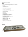
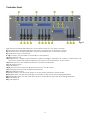
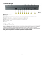
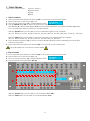
1
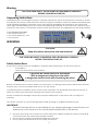
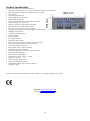
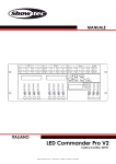
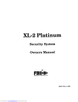
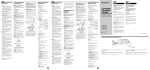
LED Commander Pro ORDERCODE 50725 Congratulations! You have bought a great, innovative product from Showtec. The Showtec LED Commander Pro brings excitement to any venue. Whether you want simple plug-&-play action or a sophisticated DMX show, this product provides the effect you need. You can rely on Showtec, for more excellent lighting products. We design and manufacture professional light equipment for the entertainment industry. New products are being launched regularly. We work hard to keep you, our customer, satisfied. For more information: [email protected] You can get some of the best quality, best priced products on the market from Showtec. So next time, turn to Showtec for more great lighting equipment. Always get the best -- with Showtec ! Thank you! Showtec Showtec LED Commander Pro™ Product Guide Warning ...............................................................................................................................................................................2 Safety Instructions .........................................................................................................................................................2 Operating Determinations ..........................................................................................................................................3 Return Procedure ..........................................................................................................................................................4 Claims ..............................................................................................................................................................................4 Description of the device .................................................................................................................................................5 Overview ........................................................................................................................................................................5 Controller Front ..............................................................................................................................................................6 Set Up and Operation .......................................................................................................................................................7 1. Patch Modes .............................................................................................................................................................8 1.1 Patch Address.....................................................................................................................................................8 1.2 Patch Name ........................................................................................................................................................8 1.3 MIDI .....................................................................................................................................................................10 1.4 AUX .....................................................................................................................................................................10 1.5 Patch more than ONE DMX Channel to the same slider .........................................................................10 2. Factory Reset ...........................................................................................................................................................10 3. Scenes .......................................................................................................................................................................11 3.1 Record a Scene ...............................................................................................................................................11 3.2 Play a Scene .....................................................................................................................................................11 4. Chases ......................................................................................................................................................................11 4.1 Record a Chase ...............................................................................................................................................11 4.2 Play a Chase .....................................................................................................................................................12 4.3 Program Fade Time and Speed per Chase Step ......................................................................................12 4.4 Delete a Chase ................................................................................................................................................12 4.5 Add an extra Step to an existing Chase .....................................................................................................12 4.6 Delete a Step from an existing Chase .........................................................................................................13 4.7 Manual/Auto / Music Mode .........................................................................................................................13 Maintenance ....................................................................................................................................................................14 Troubleshooting ...............................................................................................................................................................14 No Light .........................................................................................................................................................................14 No Response to DMX..................................................................................................................................................14 Product Specification .....................................................................................................................................................15 1 Warning FOR YOUR OWN SAFETY, PLEASE READ THIS USER MANUAL CAREFULLY BEFORE YOUR INITIAL START-UP! Unpacking Instructions Immediately upon receiving this product, carefully unpack the carton and check the contents to ensure that all parts are present, and have been received in good condition. Notify the dealer immediately and retain packing material for inspection if any parts appear damaged from shipping or the carton itself shows signs of mishandling. Save the carton and all packing materials. In the event that a fixture must be returned to the factory, it is important that the fixture be returned in the original factory box and packing. Your shipment includes: • LED Commander Pro • Incl. Power adapter 1,75m • User manual WARNING CAUTION! Keep this device away from rain and moisture! FOR YOUR OWN SAFETY, PLEASE READ THIS USER MANUAL CAREFULLY BEFORE YOUR INITIAL START-UP! Safety Instructions Every person involved with the installation, operation and maintenance of this device has to: be qualified follow the instructions of this manual CAUTION! Be careful with your operations. With a dangerous voltage you can suffer a dangerous electric shock when touching the wires! Before your initial start-up, please make sure that there is no damage caused by transportation. Should there be any, consult your dealer and do not use the device. To maintain perfect condition and to ensure a safe operation, it is absolutely necessary for the user to follow the safety instructions and warning notes written in this manual. Please consider that damages caused by manual modifications to the device are not subject to warranty. This device contains no user-serviceable parts. Refer servicing to qualified technicians only. IMPORTANT: The manufacturer will not accept liability for any resulting damages caused by the nonobservance of this manual or any unauthorized modification to the device. Never let the power-cord come into contact with other cables! Handle the power-cord and all connections with the mains with particular caution! Never remove warning or informative labels from the unit. Do not open the device and do not modify the device. 2 Never use anything to cover the ground contact. Never leave the device run without a lamp! Never look directly into the light source. Never leave any cables lying around. Do not insert objects into air vents. Do not connect this device to a dimmerpack. Do not switch the device on and off in short intervals, as this would reduce the device’s life. Do not shake the device. Avoid brute force when installing or operating the device. The LED-Foot 4 reacts very sensitive to movement. Never use the device during thunderstorms, unplug the device immediately. Only use device indoor, avoid contact with water or other liquids. Do not touch the device’s housing bare-handed during its operation (housing becomes hot). Only operate the device after having familiarized with its functions. Avoid flames and do not put close to flammable liquids or gases. Always keep case closed while operating. Always allow free air space of at least 50 cm around the unit for ventilation. Always disconnect power from the mains, when device is not used or before cleaning! Only handle the power-cord by the plug. Never pull out the plug by tugging the power-cord. Make sure that the device is not exposed to extreme heat, moisture or dust. Make sure that the available voltage is not higher than stated on the rear panel. Make sure that the power-cord is never crimped or damaged. Check the device and the powercord from time to time. If the external cable is damaged, it has to be replaced by a qualified technician. If the glass is obviously damaged, it has to be replaced. So that its functions are not impaired, due to cracks or deep scratches. If device is dropped or struck, disconnect mains power supply immediately. Have a qualified engineer inspect for safety before operating. If the device has been exposed to drastic temperature fluctuation (e.g. after transportation), do not switch it on immediately. The arising condensation water might damage your device. Leave the device switched off until it has reached room temperature. If your Showtec device fails to work properly, discontinue use immediately. Pack the unit securely (preferably in the original packing material), and return it to your Showtec dealer for service. For adult use only. Lighteffect must be installed out of the reach of children. Never leave the unit running unattended. For replacement use fuses of same type and rating only. Allow time to cool down, before replacing lamp. The user is responsible for correct positioning and operating of the LED-Foot 4. The manufacturer will not accept liability for damages caused by the misuse or incorrect installation of this device. This device falls under protection class I. Therefore it is essential to connect the yellow/green conductor to earth. During the initial start-up some smoke or smell may arise. This is a normal process and does not necessarily mean that the device is defective. Repairs, servicing and electric connection must be carried out by a qualified technician. WARRANTY: Till one year after date of purchase. Operating Determinations • This device is not designed for permanent operation. Consistent operation breaks will ensure that the device will serve you for a long time without defects. • The minimum distance between light-output and the illuminated surface must be more than 0.5 meter. • The maximum ambient temperature ta = 45°C must never be exceeded. • The relative humidity must not exceed 50 % with an ambient temperature of 45° C. • If this device is operated in any other way, than the one described in this manual, the product may suffer damages and the warranty becomes void. • Any other operation may lead to dangers like short-circuit, burns, electric shock, crash etc. You endanger your own safety and the safety of others! Improper installation can cause serious damage to people and property ! 3 Connection with the mains Connect the device to the mains with the power-plug. Always pay attention, that the right color cable is connected to the right place. International EU Cable UK Cable US Cable Pin L BROWN RED YELLOW/COPPER FASE N BLUE BLACK SILVER NUL YELLOW/GREEN GREEN GREEN EARTH Make sure that the device is always connected properly to the earth! Return Procedure Returned merchandise must be sent prepaid and in the original packing, call tags will not be issued. Package must be clearly labeled with a Return Authorization Number (RMA number). Products returned without an RMA number will be refused. Highlite will not accept the returned goods or any responsibility. Call Highlite 0031-455667723 or mail [email protected] and request an RMA prior to shipping the fixture. Be prepared to provide the model number, serial number and a brief description of the cause for the return. Be sure to properly pack fixture, any shipping damage resulting from inadequate packaging is the customer’s responsibility. Highlite reserves the right to use its own discretion to repair or replace product(s). As a suggestion, proper UPS packing or double-boxing is always a safe method to use. Note: If you are given an RMA number, please include the following information on a piece of paper inside the box: 1) Your name 2) Your address 3) Your phone number 4) A brief description of the symptoms Claims The client has the obligation to check the delivered goods immediately upon delivery for any shortcomings and/or visible defects, or perform this check after our announcement that the goods are at their disposal. Damage incurred in shipping is the responsibility of the shipper; therefore the damage must be reported to the carrier upon receipt of merchandise. It is the customer's responsibility to notify and submit claims with the shipper in the event that a fixture is damaged due to shipping. Transportation damage has to be reported to us within one day after receipt of the delivery. Any return shipment has to be made post-paid at all times. Return shipments must be accompanied with a letter defining the reason for return shipment. Non-prepaid return shipments will be refused, unless otherwise agreed in writing. Complaints against us must be made known in writing or by fax within 10 working days after receipt of the invoice. After this period complaints will not be handled anymore. Complaints will only then be considered if the client has so far complied with all parts of the agreement, regardless of the agreement of which the obligation is resulting. 4 Description of the device Features The LED Commander Pro is a light controller from Showtec and features: • The LED Commander Pro is the successor of the LED commander • The upgrade is simple but unique and very useful • Easy to use • Control 8 RGB fixtures • Adjustable Speed control • Adjustable fade time • Free patchable RGB and dimmer channels • Power supply: AC 7,5V- 2A • Power connector: Adapter (included) • All functions and faders patchable • Memory for 16 scenes and 16 chases • 2 Auxiliary channels to control foggers and strobes • 3 Bright LCD displays • 3 and 5 pole XLR output • Auto program • Music Control • 19" rackmounting • DMX-512: XLR 3 pole • Record Function to Record Colors and Chases • Speed & Fade faders for Chase control • Free patchable channels • Run mode: Auto, Music, Manual • Fixtures: 8 + 2 Aux channels • Control 8 LED fixtures up to 8 channels each • DMX-512: 66 Channels • USB: 5VDC for mini-light • Audio input: RCA, 100mv - 1Vpp • MIDI: In, Out, Thru • MIDI connector: 5P DIN • Power consumption: 20W • Dimensions: 482 x 178 x 75mm (LxWxH) • Weight: 3,1Kg NOTE: Knowledge of DMX is required to fully utilize this unit. Overview Fig. 1 5 Controller Front Fig. 2 1) Fixture buttons and LED indicators 1-8: Use Fixture button 1-8 to select a fixture. 2) Scenes buttons and LED indicators 1-8: Push a scene button to activate a scene. 3) Chase buttons and LED indicators 1-8: Push a chase button to activate a chase. 4) Aux Buttons: AUX 1 and AUX 2 5-12) 8 Faders: Use the faders to manually set the intensity. 13) Flash buttons 1-8 14) Page button + Page 1/2 LED indicators : When the Page 1 indicator is lit, scenes 1-8 and chases 1-8 are active. When the Page 2 indicator is lit, scenes 9-16 and chases 9-16 are active. 15) Record button: Use the Record button to enter Record Mode. 16) TAP SYNC button 17) LCD Display 1 18) Black Out button: Press the Black Out button to cut all output. 19) Mode/Up button incl Auto/Music/Manual LED 20) Patch/Down button 21) AUDIO Fader: Use the Audio fader to set the audio sensitivity in Music Mode. 22) SPEED Fader: Use the Speed fader to manually set the chase speed during playback. 23) FADE TIME Fader: Use the Fade Time fader to manually set the Fade Time during playback. 24) LCD Display 2 25) LCD Display 3 6 Controller Backside Fig. 3 26) DMX OUT 27) DMX Polarity Switch 28) USB Light 29) Audio Input: This jack accepts a line level audio input signal ranged from 100 mV to 1Vpp. 30) MIDI Thru: MIDI port for connection to a sequencer or MIDI device. 31) MIDI Out: MIDI port for connection to a sequencer or MIDI device. 32) MIDI In: MIDI port for connection to a sequencer or MIDI device. 33) DC power DC 7,5V 2A 34) ON/OFF Set Up and Operation Remove all packing materials from the LED Commander Pro. Check that all foam and plastic padding is removed. Connect all cables. Before plugging the unit in, always make sure that the power supply matches the product specification voltage. Do not attempt to operate a 120V specification product on 230V power, or vice versa. Remove all packing materials from the LED-Foot 4. Check that all foam and plastic padding is removed. Always disconnect from electric mains power supply before cleaning or servicing. Damages caused by non-observance are not subject to warranty. 7 1. Patch Modes There are 4 Patch Modes: 1) Patch Address 2) Patch Name 3) MIDI 4) AUX 1.1 Patch Address 1. 2. 3. 4. Press and hold the Patch/Down button (20) for 3 seconds to enter Patch Mode. The red LED next to the button lights up. Press the Tapsync button (16), until the display shows . Use the Speed slider (22) to select the Fixture you want to patch. The displays (A) above the 8 sliders (5-12) show the DMX addresses and with the 8 Sliders (B) below you can patch the slider of a Fixture to a DMX address. With the Speed slider you are able to set the channels in groups of 8, example: 001 f1s1, 009 f2s1, 017 f3s1, 025 f4s1, 033 f5s1, 041 f6s1, 049 f7s1, 057 f8s1, 065 AUX1, 073 NULL,., 505 NULL With the Fade slider you are able to view the channels in the selected group,example: 001 f1s1, 002 f1s2, 003 f1s3, 004 f1s4, 005 f1s5, 006 f1s6, 007 f1s7, 008 f1s8 5. Press the Record button (15) to save the patch. All LEDs will flash 3 times, indicating your operation has been successful. 6. Press and hold the Patch/Down button (20) for 3 seconds to exit Patch Mode. The Audio Slider has no function in Patch Mode 1.2 Patch Name 1. 2. 3. 4. Press and hold the Patch/Down button (20) for 3 seconds to enter Patch Mode. The red LED next to the button lights up. Press the Tapsync button (16), until the display shows . Use the Speed and Fade sliders (22+23). A B With the Speed slider you are able to set the fixtures: f1s1 – f8s1. With the Fade slider you are able to set desired Slider (5-12). 8 5. With the 7th slider you are able to set the desired preset name table: 6. With the 8th slider you are able to set the 8 different preset names: Tables and Preset Names Table 1 Red Green Blue White Amber UV CWhite WWhite Table 2 Hue Satur Color Strobe Speed Fade Dimmer Dim Sp Table 3 Dim 1 Dim 2 Dim 3 Dim 4 Dim 5 Dim 6 Prog Ctrl Table 4 Zoom Macro Effect Pan Tilt P/T sp Gobo 1 Gobo 2 Table 5 Focus Iris Prism Gobo R User 1 User 2 User 3 User 4 Table 6 User 5 User 6 7. You can also change the preset names into your own names by using the the first 6 sliders. Choose a specific character you want to be shown on the display. You can choose between: !”#$%&’()*+,-./0123456789:;<=>?@ABCDEFGHIJKLMNOPQRSTUVWXYZ [¥]ˆ_`abcdefghijklmnopqrstuvwxyz{|} 8. Press the Record button (15) to save the patch. All LEDs will flash 3 times, indicating your operation has been successful. 9. Press and hold the Patch/Down button (20) for 3 seconds to exit Patch Mode The Audio Slider has no function in Patch Mode 9 1.3 MIDI 1. 2. 3. 4. 5. 6. Press and hold the Patch/Down button (20) for 3 seconds to enter Patch Mode. The red LED next to the button lights up. Press the Tapsync button (16), until the display shows . Use the Speed slider (22) to choose your desired MIDI channel. You can choose 16 different MIDI channels. Press the Record button (15) to save your adjustment. All LEDs will flash 3 times, indicating your operation has been successful. 7. Press and hold the Patch/Down button (20) for 3 seconds to exit Patch Mode. 1.4 AUX 1. Press and hold the Patch/Down button (20) for 3 seconds to enter Patch Mode. 2. The red LED next to the button lights up. 3. Press the Tapsync button (16), until the display shows . 4. Use the Speed slider (22) to select 065 AUX1 or 066 AUX2. 5. 6. 7. 8. Press the Tapsync button (16), until the display shows . Use the Speed slider (22) to choose Latch or Flash. Press the Record button (15) to save the patch. Press and hold the Patch/Down button (20) for 3 seconds to exit Patch Mode. 1.5 Patch more than ONE DMX Channel to the same slider 1. 2. 3. 4. Press and hold the Patch/Down button (20) for 3 seconds to enter Patch Mode. The red LED next to the button lights up. Press the Tapsync button (16), until the display shows . Use the Speed slider (22) to select the Fixture you want to patch. The displays above the 8 sliders (5-12) show the DMX addresses and with the 8 Sliders below you can patch the slider of a Fixture to multiple DMX addresses. If you want to patch DMX address 1, 2, 3 and 4 to slider 1, change the sliders below the display to: 001 f1s1 002 f1s1 003 f1s1 004 f1s1 5. Press the Record button (15) to save the patch. All LEDs will flash 3 times, indicating your operation has been successful. 6. Press and hold the Patch/Down button (20) for 3 seconds to exit Patch Mode. The Audio Slider has no function in Patch Mode 2. Factory Reset 1. Press the Record button (15) and enter Program Mode. The red LED next to the button lights up. 2. The display shows . 3. Now press and hold the Record (15) button + Tap Sync (16) together for 10 seconds. 4. Release the 2 buttons and wait for 15 seconds. All LEDs will flash 3 times, indicating your operation has been successful. The LED Commander Pro is now back to its original factory default settings. After the factory reset, the fixture is auto patched 10 3. Scenes 3.1 Record a Scene 1. 2. 3. 4. 5. 6. 7. 8. 9. Press and hold down the the Record button (15) for 3 seconds to enter Record Mode. The red LED next to the button lights up. Select the fixture you want to program by pressing the desired Fixture button (1). Set the 8 faders (5-12) to the desired values. Select the proper Page by pressing the Page button (14). You can choose Page 1 or Page 2. The orange LED above the button lights up Select the desired chase by pressing Chase button 1-8 (3). Press the Record button (15). The red LED next to the button lights up. Now select the scene you want to program the value into by pressing the desired Scene button (2). All LEDs will flash 3 times, indicating your operation has been successful. Press and hold the Record button (15) for 3 seconds to exit Program Mode The existing scenes will be overwritten 3.2 Play a Scene 1. Deselect all fixtures. All LEDs next to the 8 fixture buttons (1) must be OFF. 2. Select the proper Page by pressing the Page button (14). You can choose Page 1 or Page 2. The orange LED above the button lights up. 3. To select the desired scene press the Scene button (2). 4. Scenes can be stored on 2 pages. Each page can contain a maximum of 8 scenes. Multiple scenes can be mixed together Scenes will react to the Fade fader (24) Be sure to use the Page button (14). As an overview you are immediately able to view which scenes are still active on which page. The LEDs, from the scene or chase that is still active, are on. 4. Chases 4.1 Record a Chase 1. Press and hold down the the Record button (15) for 3 seconds to enter Record Mode. 2. The red LED next to the button lights up. 3. Select the proper Page by pressing the Page button (14). You can choose Page 1 or Page 2. The orange LED above the button lights up. 4. Select the desired chase by pressing Chase button 1-8 (3). 5. Select the desired fixture by pressing Fixture 1-8 (1). 6. Set the 8 faders (5-12) to the desired values. 7. Press the Record button (15). All LEDs will flash 3 times, indicating your step has been recorded. 8. The display will , meaning Step 1 in your chase has been recorded. 9. For further steps repeat 6, 7 and 8, until you have completed all the desired steps in your entire chase. 10.Deselect the Chase, by pushing the Chase button. 11.Exit Record Mode by pressing the Record button (15). More than 1 fixture can be programmed/selected when creating steps in chases Example: If you’re in the 1st step of a 3-step chase, the display shows: 11 4.2 Play a Chase 1. 2. 3. 4. Deselect all fixtures. All LEDs next to the 8 fixture buttons must be OFF. Select your desired chase by pressing the Chase button. Use the Mode/Up button (19) to select: Manual, Auto or Music Mode. In Manual Mode, the steps will follow a programmed Fade and Speed, when pushing the the Tap Sync button (16) In Auto Mode, the chase will play steps automatically with a pre-programmd Fade and Speed Time. In Sound Mode, the steps will change to the beat of the music. But the steps will keep the preprogrammed Fade time. 5. To override the Programmed Fade and Speed Time, use the Speed and Fade sliders (22+23). 6. To go back to the Programmed Fade and Speed Time, push the Record button (15). Example: Chase 1 on Page 2 is active. Switch to Page 2 and activate Chase 1 The LED Operator Pro will now play Chase 1 from Page 1 and after that Chase 1 from Page 2 4.3 Program Fade Time and Speed per Chase Step 1. Press and hold down the the Record button (15) for 3 seconds to enter Record Mode. 2. The red LED next to the button lights up. 3. Select the proper Page by pressing the Page button (14). You can choose Page 1 or Page 2. The orange LED above the button lights up. 4. Select an empty chase by pressing Chase button 1-8 (3). 5. Select the fixture you want to program by pressing the desired Fixture button (1). 6. Set the 8 faders (5-12) to the desired values. 7. Use the Speed and Fade sliders (22+23) to set Fade and/or the Speed Time 8. Press the Record button (15) to save your step. All LEDs will flash 3 times, indicating your operation has been successful. 9. To add more steps to your chase, repeat steps 5-8. 4.4 Delete a Chase 1. 2. 3. 4. 5. Deselect all fixtures, scenes and chases. Press and hold down the the Record button (15) for 3 seconds to enter Record Mode. The red LED next to the button lights up. Select the proper Page by pressing the Page button (14). The orange LED next to the button lights up Press and hold the Tap Sync button (16). Now press the corresponding Chase button (3), that you want to delete. 6. All LEDs will flash 3 times, indicating your operation has been successful. 7. Exit Record Mode by pressing the Record button (15). 4.5 Add an extra Step to an existing Chase 1. 2. 3. 4. Press and hold down the the Record button (15) for 3 seconds to enter Record Mode. The red LED next to the button lights up. Select the chase you want to add a step to. Use the Mode/Up (19) and Patch/Down buttons (20) to scroll through the chase. The display will show the current step. 5. Select the fixture you want to program by pressing the desired Fixture button (1). 6. Set the 8 faders (5-12) to the desired values. 7. Press the Record button (15) to save a new step. All LEDs will flash 3 times, indicating your operation has been successful. The new step will be added after the selected one. 8. If you want to add additional steps repeat 5, 6 and 7, until you have added all the desired steps in your entire chase. 9. Turn OFF the Chase, by pushing the Chase button to deselect the chase. 10.Exit Record Mode by pressing the Record button (15). One Chase can contain a max. of 1740 steps 16 chases can contain a total of 1740 steps 12 4.6 Delete a Step from an existing Chase 1. 2. 3. 4. Press and hold down the the Record button (15) for 3 seconds to enter Record Mode. The red LED next to the button lights up. Select the chase from which you want to delete a step. Use the Mode/Up (19) and Patch/Down buttons (20) to scroll through the chase and select the step you want to delete. 5. Push the Tap Sync button (16) to delete the step. 6. All LEDs will flash 3 times, indicating the step has been successfully deleted. 7. Continue this procedure (steps 3, 4 and 5) if you want to delete multiple steps. If you are finished deleting the steps, press the Record button (15) to exit Record Mode. 4.7 Manual/Auto / Music Mode Manual 1. Press the Mode button (19) until the LED in front of Manual (number 1)lights up green. 2. With Tap Sync you can manually go through the chase steps. Fade Time (16) is available in Manual Mode Auto 1. Press the Mode button (19) until the LED in front of Auto (number 2) lights up green. 2. You can control the Speed and Fade Time by adjusting the Speed and Fade Time fader (22+23). Music 1. Press the Mode button (19) until the LED in front of Music (number 3) lights up green. 2. You can control the Audio sensitivity by adjusting the Audio fader (21). Fade Time is available in Music Mode The LED Commander Pro can be used as a plug-and-play device with the following Showtec products: 42431 Par 64 Short, RGB LED 42432 Par 64 Short, RGB LED 42421 Par 56 Short, RGB LED 42422 Par 56 Short, RGB LED 42400 LED Pinspot 42401 LED Pinspot 42410 Par 36 Short, RGB LED 42411 Par 36 Short, RGB LED 42460 LED RGB Par 64 High Power 18 x 3W 42461 LED RGB Par 64 High Power 18 x 3W 42435 LED Par 64, 24 x 1W 42436 LED Par 64, 24 x 1W 13 Maintenance The operator has to make sure that safety-relating and machine-technical installations are to be inspected by an expert after every year in the course of an acceptance test. The operator has to make sure that safety-relating and machine-technical installations are to be inspected by a skilled person once a year. The following points have to be considered during the inspection: 1. All screws used for installing the device or parts of the device have to be tightly connected and must not be corroded. 2. There may not be any deformations on housings, fixations and installation spots. 3. Mechanically moving parts like axles, eyes and others may not show any traces of wearing. 4. The electric power supply cables must not show any damages or material fatigue. The Showtec LED Commander Pro requires almost no maintenance. However, you should keep the unit clean. Disconnect the mains power supply, and then wipe the cover with a damp cloth. Do not immerse in liquid. Do not use alcohol or solvents. Keep connections clean. Disconnect electric power, and then wipe the DMX and audio connections with a damp cloth. Make sure connections are thoroughly dry before linking equipment or supplying electric power. Troubleshooting No Light This troubleshooting guide is meant to help solve simple problems. If a problem occurs, carry out the steps below in sequence until a solution is found. Once the unit operates properly, do not carry out following steps. If the LED Commander Pro does not operate properly, refer servicing to a technician. Response: Suspect two potential problem areas: the power supply, the LEDs. 1. Power supply. Check that the unit is plugged into an appropriate power supply. 2. The LEDs. Return the LED Commander Pro to your Showtec dealer. 3. A led effect does not respond to the LED Commander Pro: Check the DMX-address of the fixture and the controller. Make sure they match. Make sure the connections are correct. Check if blackout is off. 4. If all of the above appears to be O.K., plug the unit in again. 5. If nothing happens after 30 seconds, unplug the device. 6. If you are unable to determine the cause of the problem, do not open the LED Commander Pro, as this may damage the unit and the warranty will become void. 7. Return the device to your Showtec dealer. No Response to DMX Response: Suspect the DMX cable or connectors, a controller malfunction, a light effect DMX card malfunction. 1. Check the DMX setting. Make sure that DMX addresses are correct. 2. Check the DMX cable: Unplug the unit; change the DMX cable; then reconnect to electrical power. Try your DMX control again. 3. Determine whether the controller or light effect is at fault. Does the controller operate properly with other DMX products ? If not, take the controller in for repair. If so, take the DMX cable and the light effect to a qualified technician. 14 Product Specification Model: Showtec LED Commander Pro • The LED Commander Pro is the successor of the LED commander • The upgrade is simple but unique and very useful • Easy to use • Control 8 RGB fixtures • Adjustable Speed control • Adjustable fade time • Free patchable RGB and dimmer channels • Power supply: AC 7,5V- 2A • Power connector: Adapter (included) • All functions and faders patchable • Memory for 16 scenes and 16 chases • 2 Auxiliary channels to control foggers and strobes • 3 Bright LCD displays • 3 and 5 pole XLR output • Auto program • Music Control • 19" rackmounting • DMX-512: XLR 3 pole • Record Function to Record Colors and Chases • Speed & Fade faders for Chase control • Free patchable channels • Run mode: Auto, Music, Manual • Fixtures: 8 + 2 Aux channels • Control 8 LED fixtures up to 8 channels each • DMX-512: 66 Channels • USB: 5VDC for mini-light • Audio input: RCA, 100mv - 1Vpp • MIDI: In, Out, Thru • MIDI connector: 5P DIN • Power consumption: 20W • Dimensions: 482 x 178 x 75mm (LxWxH) • Weight: 3,1Kg Design and product specifications are subject to change without prior notice. Website: www.Showtec.info Email: [email protected] 15