1
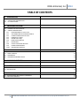
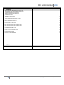
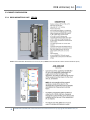
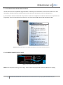
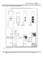
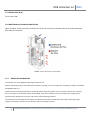
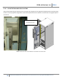
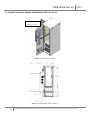
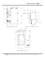
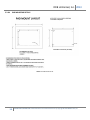
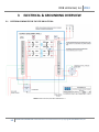
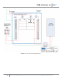
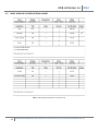
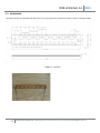
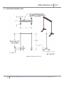
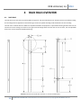
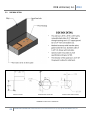
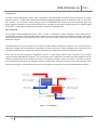
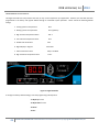
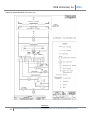
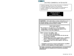
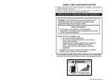
Enclosure Manual
DDB Unlimited, Inc.
Manual for the LTEE-OA Enclosure
4/29/2013
Version 2; RHD
DDB Unlimited, Inc. 2013
TABLE OF CONTENTS
1
INTRODUCTION
4
2
ENCLOSURE OVERVIEW
4
1.1
1.2
1.3
PURPOSE
CONTENT AND ORGANIZATION
ETL CERTIFICATION
4
4
4
2.1 MATERIAL
2.2 POWDER COAT SPECIFICATION
2.3 CABINET CONFIGURATION
2.3.1
DOOR MOUNTED AC UNIT LTEE-A
2.3.2
AIR CONDITIONER WITH REMOTE DISPLAY
2.3.3
CURRENT REMOTE DISPLAY VIEW
2.3.4
IQ6000VS CUT SHEET
2.3.5
SOUND LEVEL db(A)
2.3.6
DIRECTIONAL AIRFLOW
2.3.7
SEER RATING
2.3.8
SUPPLY AND RETURN DUCTING
2.3.9
CABINET DIMENSIONING
2.3.9A PAD MOUNTING DETAILS
4
5
6
6
7
7
8
9
9
9
10
11
13
3
ELECTRICAL & GROUNDING OVERVIEW
14
3.1
3.2
3.3
3.4
ELECTRICAL SCHEMATICS
PANEL SCHEDULE
GROUND BAR
GROUND BAR ASSEMBLY DETAIL
14
16
17
18
4
RACK RAILS OVERVIEW
19
RACK RAILS
19
5
BATTERY BOX & SIDE BOX OVERVIEW
21
4.1
5.1 BATTERY BOX EXHAUST FANS
5.2 SIDE BOX DETAIL
21
22
6
23
APPENDICES
6.1 AIR CONDITIONER OPS MANUAL & WARRANTY
6.2 ENCLOSURE WARRANTY
2
CONFIDENTIAL & PROPRIETARY: Limited Distribution to Authorized Persons Only. Copyright © 2013 DDB Unlimited, Inc.
23
37
DDB Unlimited, Inc. 2013
7
1
2
3
4
5
6
7
8
9
10
11
12
13
14
15
16
17
18
19
20
21
22
8
1
FIGURES
BASIC COMPONENT BREAKDOWN FOR THE LTEE-OA
BASIC AIRFLOW AND CLIMATE CONTROL DESCRIPTION
IQ 6000 VS (with external control display)
REMOTE DISPLAY FOR AIR CONDITIONER
IQ 6000 VS CUT SHEET
AC UNIT DIRECTIONAL AIR FLOW DIAGRAM
RETURN AND SUPPLY DUCTS
ISOMETRIC VIEW OF THE LTEE-OA
FRONT DIMENSIONAL VIEW OF THE LTEE-OA
RIGHT SIDE VIEW OF THE LTEE-OA
TOTAL OCCUPIED SPACE OF THE LTEE-OA
LEFT SIDE VIEW OF THE LTEE-OA
PADMOUNTING DETAIL
ANSI TITLE BLOCK, ELECTRICAL SCHEMATIC PG. 1
ANSI TITLE BLOCK, ELECTRICAL SCHEMATIC PG. 2
12” GROUNDBAR
GROUNDBAR ASSEMBLY DETAIL
RACK RAIL DETAIL
DETAIL “F” OF THE RACK RAIL DETAIL
½” GROUND STRAP FOR THE LTE SERIES RACK RAILS
DC AXIAL EXHAUST FANS
SIDE BOX DETAIL & DIMENSIONS
TABLES
PANEL SCHEDULE FOR BOTH THE LTEE-OA & LTEE-OD
3
CONFIDENTIAL & PROPRIETARY: Limited Distribution to Authorized Persons Only. Copyright © 2013 DDB Unlimited, Inc.
6
6
7
7
8
9
10
11
11
12
12
12
13
14
15
17
18
19
20
20
21
22
16
DDB Unlimited, Inc. 2013
1
INTRODUCTION
1.1 PURPOSE
This document is intended to describe the LTEE-OA (ACU Cooled/Closed Loop) enclosure.
1.2 CONTENT AND ORGANIZATION
This document consists of 6 chapters including appendices, figures and tables.
1.3 ETL CERTIFICATION
This document section will contain excerpts from ETL DRAFT Report No.100393104DAL-001, issued for review
on: 27-May-2011. A full copy of the ETL listing report can be obtained by contacting DDB Unlimited. This Section
is to be completed upon final ETL certification.
2
ENCLOSURE OVERVIEW
2.1 MATERIAL
The ASTM B209-04 is the material standard for our Aluminum class 5052h32 manufacture. ASTM B209-04 can be sold
and or used in special fire rated categories such as fire block between buildings or fire protection of critical supports.
The standard flash point of 5052h32 is 606 degrees C. Aluminum 5052h32 is considered RoHS compliant by both
American and European Standards agencies.
Reference: ASTM B209-04 “standard Specification for Aluminum and Aluminum-Alloy Sheet and Plate”
4
CONFIDENTIAL & PROPRIETARY: Limited Distribution to Authorized Persons Only. Copyright © 2013 DDB Unlimited, Inc.
DDB Unlimited, Inc. 2013
2.2 POWDER COAT SPECIFICATION – Provided by Diamond Vogel.
5
CONFIDENTIAL & PROPRIETARY: Limited Distribution to Authorized Persons Only. Copyright © 2013 DDB Unlimited, Inc.
DDB Unlimited, Inc. 2013
2.3 CABINET CONFIGURATION
2.3.1 DOOR MOUNTED AC UNIT: LTEE-OA
FIGURE 1: BASIC COMPONENT BREAKDOWN FOR THE LTEE-OA (above). FIGURE 2: BASIC AIRFLOW AND CLIMATE CONTROL DESCRIPTION (below).
6
CONFIDENTIAL & PROPRIETARY: Limited Distribution to Authorized Persons Only. Copyright © 2013 DDB Unlimited, Inc.
DDB Unlimited, Inc. 2013
2.3.2 AIR CONDITIONER WITH REMOTE DISPLAY
The LTEE-OA comes with an IQ 6000 BTU programmable air conditioning unit with 400 watts of internal heat installed on the door.
The display is remotely mounted to the interior portion of the door and is connected to the unit via a wiring harness.
(1) Air conditioner manual is included with every enclosure. Please see the supplied air conditioner manual for AC unit operation and
programming. If there are operational issues with the AC unit, please contact DDB Unlimited: 800-753-8459 ext. 2883.
FIGURE 3: IQ 6000 VS with external control display. NOTE: Display is now mounted to the inside of the door.
2.3.3 CURRENT REMOTE DISPLAY VIEW
FIGURE 4: REMOTE DISPLAY FOR AIR CONDITIONER.
NOTE: AC unit Set points are 65 deg. F and 77 deg. F. These set points are programmed and tested by DDB prior to shipping.
7
CONFIDENTIAL & PROPRIETARY: Limited Distribution to Authorized Persons Only. Copyright © 2013 DDB Unlimited, Inc.
DDB Unlimited, Inc. 2013
2.3.4 CUT SHEET FOR THE IQ 6000 VS AIRCONDITIONER
FIGURE 5: IQ 6000 VS CUT SHEET.
8
CONFIDENTIAL & PROPRIETARY: Limited Distribution to Authorized Persons Only. Copyright © 2013 DDB Unlimited, Inc.
DDB Unlimited, Inc. 2013
2.3.5 SOUND LEVEL db (A)
This is section TBD.
2.3.6 DIRECTIONAL AIR FLOW DOCUMENTATION
Figure 22; below, visually represents the flow of air into the AC unit from the outside as well is the intake and exhaust
from within the enclosure.
FIGURE 6: AC UNIT DIRECTIONAL AIR FLOW DIAGRAM
2.3.7
SEER RATING INFORMATION
The following is for the IQ 6000 BTU 220v programmable AC unit.
Based on BTUH cooling output and model watt consumption at 95 deg. F return air temperature and 95 deg. F ambient, the SEER for
the IQ6000VS-236 is 8.1.
Please note when comparing these SEER to "advertised" SEER of consumer products, these may seem on the low side. However,
there are variations in the methods used to calculate SEER. Some of the variations are hours of operation per cooling season,
physical location (temperature zone), test methods and system operating conditions.
The method used for calculation of the Ice Qube cooling systems is based on a formula from Heat Pump Technology by Billy C.
Langley, Second Edition, intended as a text book for study in the HVACR curriculum.
9
CONFIDENTIAL & PROPRIETARY: Limited Distribution to Authorized Persons Only. Copyright © 2013 DDB Unlimited, Inc.
DDB Unlimited, Inc. 2013
2.3.8
AC UNIT RETURN AND SUPPLY DUCTING
After extensive field testing, the following return and supply duct configuration was designed and implemented for improved cooling
function in various equipment configurations and has been implemented into the LTEE-OA as a standard and as an upgrade option in
the LTEE-OD.
STANDARD RETURN AND SUPPLY
DUCTING FOR THE LTEE-A
FIGURE 7: RETURN AND SUPPLY DUCTS MOUNTED TO THE INSIDE OF THE FRONT DOOR
10
CONFIDENTIAL & PROPRIETARY: Limited Distribution to Authorized Persons Only. Copyright © 2013 DDB Unlimited, Inc.
DDB Unlimited, Inc. 2013
2.3.9 CABINET VIEWS AND OVERALL DIMENSIONING FOR THE LTEE-OA
STANDARD RETURN AND SUPPLY
DUCTING FOR THE LTEE-OA
FIGURE 8: ISOMETRIC VIEW OF THE LTEE-OA
FIGURE 9: FRONT DIMENSIONAL VIEW OF THE LTEE-OA
11
CONFIDENTIAL & PROPRIETARY: Limited Distribution to Authorized Persons Only. Copyright © 2013 DDB Unlimited, Inc.
DDB Unlimited, Inc. 2013
FIGURE 10: RIGHT SIDE VIEW OF THE LTEE-OA
FIGURE 11: TOTAL OCCUPIED SPACE OF THE LTEE-OA
FIGURE 12: LEFT SIDE VIEW OF THE LTEE-OA
12
CONFIDENTIAL & PROPRIETARY: Limited Distribution to Authorized Persons Only. Copyright © 2013 DDB Unlimited, Inc.
DDB Unlimited, Inc. 2013
2.3.9A
PAD MOUNTING DETAILS
BOTTOM OF THE LTEE-OA (TOP VIEW)
FIGURE 13: PADMOUNTING DETAIL
13
CONFIDENTIAL & PROPRIETARY: Limited Distribution to Authorized Persons Only. Copyright © 2013 DDB Unlimited, Inc.
DDB Unlimited, Inc. 2013
3
3.1
ELECTRICAL & GROUNDING OVERVIEW
ELECTRICAL SCHEMATIC FOR THE LTEE-OD & LTEE-OA
FIGURE 14: ANSI TITLE BLOCK, ELECTRICAL SCHEMATIC PG. 1
14
CONFIDENTIAL & PROPRIETARY: Limited Distribution to Authorized Persons Only. Copyright © 2013 DDB Unlimited, Inc.
DDB Unlimited, Inc. 2013
FIGURE 15: ANSI TITLE BLOCK, ELECTRICAL SCHEMATIC PG. 2
15
CONFIDENTIAL & PROPRIETARY: Limited Distribution to Authorized Persons Only. Copyright © 2013 DDB Unlimited, Inc.
DDB Unlimited, Inc. 2013
3.2
PANEL SCHEDULE FOR THE ELECTRICAL LAYOUT
TABLE 1: PANEL SCHEDULE FOR BOTH THE LTEE-OA & LTEE-OD
16
CONFIDENTIAL & PROPRIETARY: Limited Distribution to Authorized Persons Only. Copyright © 2013 DDB Unlimited, Inc.
DDB Unlimited, Inc. 2013
3.3 GROUND BAR
The side box of both the LTEE-OD & LTEE-OA contain a 12” copper ground bar mounted on isolators. Please see the figure below.
FIFigure
FIGURE 16: 12” GROUNDBAR
17
CONFIDENTIAL & PROPRIETARY: Limited Distribution to Authorized Persons Only. Copyright © 2013 DDB Unlimited, Inc.
DDB Unlimited, Inc. 2013
3.4 GROUND BAR ASSEMBLY DETAIL
FIGURE 17: GROUNDBAR ASSEMBLY DETAIL
18
CONFIDENTIAL & PROPRIETARY: Limited Distribution to Authorized Persons Only. Copyright © 2013 DDB Unlimited, Inc.
DDB Unlimited, Inc. 2013
4
4.1
RACK RAILS OVERVIEW
RACK RAILS
The rack rails for the LTE series are pictured below in Figure 34. They are made from 0.125” aluminum and have an Alodine coating.
The mounting holes are tapped for a 10-32 mounting screw and are spaced according to EIA standard for 19” rack mounting.
The rack rails are etched with RU numbers for simplified installation of equipment to a prescribed mounting location. Rack rails are
oriented so the RU markings are visible on the right hand rail through either the front door or the rear door; rails are adjustable
front to rear to aid in equipment profile positioning.
FIGURE 18: RACK RAIL DETAIL: PLEASE NOTE THAT DETAIL “F” IS ON THE FOLLOWING PAGE.
19
CONFIDENTIAL & PROPRIETARY: Limited Distribution to Authorized Persons Only. Copyright © 2013 DDB Unlimited, Inc.
DDB Unlimited, Inc. 2013
FIGURE 19: DETAIL “F” OF THE RACK RAIL DETAIL FROM THE PREVIOUS PAGE
Additionally, there is a ½” bridge strap that is mounted in top ½” of each rail for additional grounding. See notes within Figure 36.
FIGURE 20: ½” GROUND STRAP FOR THE LTE SERIES RACK RAILS.
Double Lug rail mounted.
20
Double Lug ground bar mounted.
CONFIDENTIAL & PROPRIETARY: Limited Distribution to Authorized Persons Only. Copyright © 2013 DDB Unlimited, Inc.
DDB Unlimited, Inc. 2013
5
5.1
BATTERY BOX & SIDE BOX OVERVIEW
BATTERY BOX EXHAUST FANS
In line fuse protection here.
The LTE series has a direct air ventilated dual shelf battery compartment designed to hold up to strings of (4) 12v, 180ah VRLA
Telecom batteries. The intake filter is mounted to the front door and the exhaust on the rear door. See FIGURE 18 for airflow detail.
The battery compartment is ventilated with (2) 48v 110cfm fans. See fan detail below.
FIGURE 21: DC AXIAL EXHAUST FANS FOR THE BATTERY COMPARTMENT
21
CONFIDENTIAL & PROPRIETARY: Limited Distribution to Authorized Persons Only. Copyright © 2013 DDB Unlimited, Inc.
DDB Unlimited, Inc. 2013
5.2
SIDE BOX DETAIL
SIDE BOX TOP VIEW
UNDERSIDE VIEW OF SIDE BOX
NOTCHED CABLE INSERTION POINT
FIGURE 22: SIDE BOX DETAIL & DIMENSIONS
22
CONFIDENTIAL & PROPRIETARY: Limited Distribution to Authorized Persons Only. Copyright © 2013 DDB Unlimited, Inc.
DDB Unlimited, Inc. 2013
6 APPENDICES:
6.1 AIR CONDITIONER OPERATING MANUAL
Intelligent Electronic Enclosure
Thermal Management Systems
OPERATION AND INSTALLATION MANUAL
*** IMPORTANT ***
PLEASE READ this manual and follow the instructions for safe and satisfactory installation and operation
of this system. Keep this manual for future reference. Some information may not apply to all systems.
23
CONFIDENTIAL & PROPRIETARY: Limited Distribution to Authorized Persons Only. Copyright © 2013 DDB Unlimited, Inc.
DDB Unlimited, Inc. 2013
INTRODUCTION:
Ice Qube’s Thermal Management System, TMS, is designed to cool, dehumidify or heat the internal environment of modern
electrical enclosures. Ice Qube offers efficient and aesthetically appealing packages that can be mounted on top or on the side of
your enclosure. Our closed-loop circulation design protects your equipment from air-borne dust and contaminants which may
hinder equipment operations, causing unnecessary down time. Ice Qube is able to provide cooling capacities from 1,000 to 20,000
BTU per hour - a wide range of cooling systems to satisfy many of your conditioning needs.
BASIC OPERATION:
The Ice Qube’s Thermal Management System, TMS, is actually a combination of three independent systems which function
simultaneously to maintain environmentally friendly conditions for various types of electronic equipment enclosures. These three
thermal related systems are: the closed-loop cool air system; the warm air system; and the vapor-compression refrigeration system.
Please refer to Figure 1.
The closed-loop cool air system circulates cold air from the Ice Qube TMS to the electronics enclosure. This air returns to the Ice
Qube system bringing with it unwanted heat and humidity from inside the enclosure. Heat and humidity is then removed by a heat
exchanger located within the Ice Qube TMS. This heat exchanger is part of the vapor-compression refrigeration system.
At the heart of the vapor-compression refrigeration’s system is a quiet, energy efficient rotary compressor which circulates
environmentally friendly NON-CFC refrigerant. The main purpose of this compressor is to transfer heat laden refrigerant from the
evaporator, located within the closed-loop cool air system, to a condenser, located in the warm air system. In the warm air system,
air is circulated from the ambient surrounding the enclosure, through a filter, and across the warm air system heat exchanger. Here,
heat from the enclosure is transferred from the warm air heat exchanger into the warm air stream and dissipated to the ambient.
Figure 1: Flow Diagram
24
CONFIDENTIAL & PROPRIETARY: Limited Distribution to Authorized Persons Only. Copyright © 2013 DDB Unlimited, Inc.
DDB Unlimited, Inc. 2013
UNPACKING INSPECTION:
1.
The shipping container leaves the factory banded to a pallet with red arrows imprinted on the box. These red arrows should be
pointing in the proper (upward) direction. The Ice Qube TMS is position sensitive. Ice Qube recommends the unit to remain in
the proper upright position for a minimum of 24 hours before initial operation. This is to ensure the oil has returned to the
compressor. Operation before the 24 hour time period may cause damage to the compressor, hence shortening the life of the
system.
Note: Operating the unit before maintaining an upright position for 24 hours will void all warranties.
2.
Check for any damage to the shipping container. If the shipping container has been damaged or marred in any way, carefully
check to see if the Ice Qube TMS incurred any damage. Check for scratches, dents, rattles (which may indicate loose
components), the presence of oil, and any other irregularities. Any evidence of damage will need to be recorded on the freight
bill and reported to the carrier. The freight carrier will provide instructions on filing a claim. Ice Qube cannot accept
responsibility for damages that occur during shipping.
PRE-INSTALLATION TEST:
Before installing the Ice Qube system on the enclosure, it is recommended the unit operate for 20 to 30 minutes to ensure it is
functioning properly. Although the Ice Qube TMS has been tested at the factory, internal damage may have occurred during
shipping which may have not been apparent during the unpacking inspection.
1.
Place the system on a solid base such as a workbench or table. Verify whether the unit is a Top or a Side Mount air conditioner.
Be sure to allow adequate space for airflow. There are two air streams that must not be restricted, the cool air stream and the
warm air stream. Top mount units must be elevated to provide adequate airflow for the cool air stream located on the bottom
of the system.
Top mount units can only be mounted on a flat horizontal surface. Side-mount and Bottom flow units can only be mounted on a
flat vertical surface.
Figure 2: Top mounted unit
25
Figure 3: Side mounted unit
CONFIDENTIAL & PROPRIETARY: Limited Distribution to Authorized Persons Only. Copyright © 2013 DDB Unlimited, Inc.
DDB Unlimited, Inc. 2013
PRE-INSTALLATION TEST: -continued2.
Check that the warm air system filter is in place, location varies with model type.
Models with the optional rain or wash down hood do not have a warm air filter and will require regular routine condenser
maintenance.
3.
Check the data tag for proper electrical requirements. The data tag lists the design voltage and amperage requirements of the
system. Verify that the electrical outlet where the system will be connected has the proper capacity. After noting the above,
connect the power cord to a properly grounded electrical connection. The use of an extension cord is not recommended.
NOTE:
If any unusual noise or vibration is present during the testing procedure, immediately disconnect the power
cord and inspect the unit for the cause of the noise or vibration. Contact Ice Qube immediately.
4. As soon as power is supplied to the system, the cool air evaporator blower will begin to operate, (excluding Top mount models –
see following note). The compressor and warm air condenser blower will not operate if the room air temperature is below 80°F.
This is due to the fact the programmable controller has a factory setpoint of 80°F. (The digital display on the face of the
controller will be displaying room temperature.) If the display is indicating 80°F or warmer, the “Cool” status LED will flash for
3½ minutes before the compressor and the warm air condenser blower will operate.
NOTE:
Top mount unit evaporator blowers are electrically connected to cycle with the compressor and condenser
blower.
If the display is indicating a temperature less than 80°F, adjust the setpoint to a temperature lower than the room temperature
in order for the compressor and warm air condenser blower to operate. Refer to the “Programming the Controller” section of
this manual in order to change the factory set points.
5.
With the compressor and both blowers functioning, allow the unit to operate for 20 to 30 minutes. This will provide sufficient
time for the vapor compression system to achieve equilibrium. Measure the cool air outlet temperature with an accurate
thermometer. This temperature should be at least 10 degrees colder than the inlet air temperature, (if the room temperature is
warmer than 70°F). Inlet air temperature will be displayed on the programmable controller. In areas of high humidity, the
temperature difference may be less than 10 degrees.
6.
After completing the above check points, the electrical enclosure is ready to be prepared for the installation of the Ice Qube
system.
26
CONFIDENTIAL & PROPRIETARY: Limited Distribution to Authorized Persons Only. Copyright © 2013 DDB Unlimited, Inc.
DDB Unlimited, Inc. 2013
PREPARING THE ENCLOSURE:
Ice Qube air conditioning systems have been designed to be light weight for ease of installation. Side enclosure or vertical mount
units have been designed with a simple “two stud” alignment feature to make initial fastening to the enclosure quick and easy. A
few modifications must be made to the enclosure to provide proper airflow, to maintain enclosure integrity, and to assure a secure
installation. Required modifications will vary with each air conditioner model.
1.
Determine the location of the Ice Qube system on the enclosure.
*** CAUTION ***
Verify the weight of the air conditioning system will not cause the enclosure to become unbalanced. Equipment
instability may cause bodily harm or equipment damage. For units mounted on enclosure doors, confirm the
hinges will support the weight of the Ice Qube system. Refer to system specifications for model weights.
2.
Upon deciding the location of the Ice Qube system on the enclosure, attach the included template to the enclosure surface.
This template drawing will assist the installer in placing the air conditioning unit on the enclosure. Be sure the Ice Qube system
will be mounted level and the cool air inlet and outlet connections will not be restricted by equipment or shelving within the
enclosure. Also check that the air flow of the warm air stream will not be effected or restricted by the surroundings.
3.
Outline the modifications for the enclosure with a marking pencil. Note the bolt hole locations, the cutouts for the inlet and
outlet air streams, the power cord and the locations for any optional equipment. Additional cable openings may be required for
units with optional heating or alarm outputs, or for units connected to a network communications link.
4.
Using a drill, make the holes for the studs, bolts and power cord and any other option. The bit size will need to vary depending
upon the model. Protect any equipment located within the enclosure from debris produced during the installation procedure.
5.
Drill a pilot hole for a saber saw to cut the inlet and outlet air passages. File all cuts to provide a uniform cutout.
6.
Slide the mounting studs through the matching holes in the enclosure. Verify that all of the openings are aligned. Top mount
units do not have mounting studs.
7.
After checking that all openings and bolt holes are in alignment, apply the gasket material provided to the Ice Qube air
conditioning system cabinet to ensure enclosure integrity.
*** CAUTION ***
Be careful while removing the backing on the gasket material. The material may stretch and the holes will
not align.
NOTE:
27
If the enclosure is not air tight or the air conditioning system operates with the enclosure door(s) open,
moisture will condensate inside the air conditioning system and may cause the condensate management
system to overflow.
CONFIDENTIAL & PROPRIETARY: Limited Distribution to Authorized Persons Only. Copyright © 2013 DDB Unlimited, Inc.
DDB Unlimited, Inc. 2013
8.
After the gasket material has been installed, mount the Ice Qube system onto the enclosure and fasten it using the supplied
nuts and bolts. Check to see if the power cord and all optional cables are in place. Fasteners need to be tightened securely and
the gasket material needs to be in place in order to maintain enclosure integrity. The gasket material should be slightly
compressed with no visible gaps. The Ice Qube system is now ready to begin operation.
NOTE:
Near the bottom or on the side of the Ice Qube system cabinet is a nipple for condensate overflow.
Although all vertical or side mounted Ice Qube air conditioners have built-in condensate management
systems, it may be necessary to attach a drain hose to this nipple on enclosures which are located in
extremely humid conditions, or where enclosure doors are left open or the door seals are leaking.
Top mount models do not have a built in condensate evaporation system. In order for the drainage system
to operate properly, the factory supplied drain kit with a “Tee” must be installed per factory instructions.
Ice Qube cannot be held responsible for improper installation.
OPERATING THE SYSTEM:
Once the Ice Qube system has been installed onto the enclosure and the power cord has been attached to a properly grounded
electrical outlet with adequate voltage and current supply, the unit is ready for operation. As soon as electrical power is supplied to
the Ice Qube system, the cool air stream blower will start to operate, (except for Top mount units). The blower will run continuously
so that the controller can monitor the enclosure’s internal temperature. The enclosure temperature will be displayed on the face of
the controller.
If the enclosure temperature is greater than the factory cooling setpoint of 80°F, the “Cool” status LED will flash. This indicates that
the compressor’s automatic off cycle timer is working. (The off cycle timer is factory set at 3½ minutes). At the end of 3½ minutes,
the compressor and the condenser air blower will begin to operate. This signifies that the cooling system has begun operation to
remove heat and humidity from the enclosure. This procedure may take 20 to 30 minutes before it reaches full capacity.
If the heat load within the enclosure is less than the cooling capacity of the Ice Qube system, the temperature on the digital display
will begin to decrease. When the temperature inside the enclosure decreases 7 degrees Fahrenheit below the “Cooling on”
setpoint, the compressor and the condenser blower will cycle off. The cool air blower will continue to operate, circulating air within
the enclosure. The controller has a factory programmed temperature differential of 7 degrees Fahrenheit. Example: “Cooling on”
@ 80°F; “Cooling off” @ 73°F.
Ice Qube also offers two heat options: an External Heat Output (EHO) which provides power to an external heater typically located
within the equipment enclosure; and an Internal Heat Output (IHO) which provides a heater located within the air conditioning unit.
If the enclosure temperature is below the factory heating setpoint of 50º F, the heat status LED will be ‘”on”. This indicates the heat
relay has been energized and is providing power to the heater. (There is no time delay before heating begins). When the
temperature of the enclosure rises 7 degrees Fahrenheit above the setpoint, the controller will de-energize the heat relay and cycle
the heater “off”.
NOTE:
There is a dead band programmed into the controller that prevents heating and cooling from operating
simultaneously.
See the label attached to the rear of the air conditioner for maximum wattage requirement of the
heater(s).
28
CONFIDENTIAL & PROPRIETARY: Limited Distribution to Authorized Persons Only. Copyright © 2013 DDB Unlimited, Inc.
DDB Unlimited, Inc. 2013
PROGRAMMING THE CONTROLLER:
The digital controller has many features that may or may not be required for your application. However, the controller has been
programmed at the factory with typical default settings for immediate system operation. Please review the following default
settings:
1. Cooling system on temperature
80° F
2. Heating system on temperature
50° F (optional)
3. High enclosure temperature alarm
100° F
4. Low enclosure temperature alarm
40° F
5. Audible and Visual alarm
“ON”
6. Digital display in degrees
Fahrenheit
7. Filter maintenance alarm
0 days - Disabled
8. High condenser temperature alarm
170° F
Figure 4: Digital Controller
To change the factory default settings, enter the programming code sequence:
“1 Adjust-up” arrow
“2 Adjust-down” arrow
“3 Select”
“4 Exit”
29
CONFIDENTIAL & PROPRIETARY: Limited Distribution to Authorized Persons Only. Copyright © 2013 DDB Unlimited, Inc.
DDB Unlimited, Inc. 2013
After pressing the above sequence the program LED should illuminate along with three alternating flashing boxes on the display
face, indicating the code was accepted. If no selection is made within one minute, the system returns to the normal operating
mode.
Note:
Pressing the “4 Exit” button at any time while in the programming mode returns the controller to the
normal operating mode.
Press the “3 Select” button to continue programming. The set temperature “HI” LED illuminates with the display indicating the
‘cooling on’ setpoint. The compressor will begin operation at this temperature and will remain operating until the enclosure
temperature decreases approximately seven degrees Fahrenheit (four degrees Celsius). Press the “1 Adjust-up” or “2 Adjust-down”
arrow until the desired set point is displayed. The range for this adjustment is 70° to 126°F, (21° to 52°C). When the adjustment is
complete, press the “3 Select” button to continue.
PROGRAMMING THE CONTROLLER: -continuedThe set temperature “LO” LED is on with the display indicating the (optional) ‘heating on’ set point. The heating system will begin
operation at this temperature and remain operating until the enclosure temperature increases approximately seven degrees
Fahrenheit (four degrees Celsius). Press the “1 Adjust-up” or “2 Adjust-down” arrow until the desired set point is displayed within a
range of 0°F to 63°F (-17.8°C to +17°C).
NOTE:
Review alarm settings if the ‘cool on’ or ‘heat on’ set points have been changed.
Press the “3 Select” button to continue. The set alarm “HI” LED is on with the display indicating the high temperature alarm
setpoint. The alarm will activate at this temperature and will automatically reset at two degrees Fahrenheit (one degree Celsius)
below this temperature. Press the “1 Adjust-up” or “2 Adjust-down” arrow to change the alarm setpoint within a range of 8ºF (or
4ºC) above the set temperature “HI” set point, to 135°F (or 57°C).
Press the “3 Select” button to continue. The set alarm “LO” LED is on with the display indicating the low temperature alarm set
point. The alarm will activate at this temperature and will automatically reset at two degrees Fahrenheit (or one degree Celsius)
above this temperature. Press the “1 Adjust-up” or “2 Adjust-down” arrow to change the alarm setpoint within a range of 8º F
(4ºC) below the set temperature “LO” set point to -20°F (or -29°C).
Press the “3 Select” button to continue. The alarm LED will flash and the display will show “ALL”, indicating the “ALL” alarm on/off
status. Press “3 Select” and the display will show either “ON” or “OFF”, indicating current alarm status. Press “1 Adjust-up” or “2
Adjust-down” to toggle the mode as desired. If the “OFF” mode is selected, no alarms will activate and the audible on/off select
function is skipped.
Press the “3 Select” button to continue. The audible LED will flash and the display will show “AUD”, indicating the audible alarm
on/off status. Press “3 Select” and the display shows “ON” or “OFF” indicating the current audible alarm status. Press “1 Adjustup” or “2 Adjust-down” arrow to toggle the mode desired.
Press the “3 Select” button to continue. The “C” LED flashes and the display shows either “F” for degrees Fahrenheit or “C” for
degrees Celsius. Press the “1 Adjust-up” arrow or “2 Adjust-down” arrow to toggle the mode as desired.
Press the “3 Select” button to continue. The code LED is on and the display shows “PIN”. To set a new user PIN code, press the “1
Adjust-up” button. The display will flash “4”, prompting an entry of a four button sequence using the “1 Adjust-up”, “2 Adjustdown”, “3 Select” and/or “4 Exit” buttons. (Any sequence of the four buttons may be programmed as the code.) As the buttons are
pressed, the display will show the number of buttons that were pressed.
30
CONFIDENTIAL & PROPRIETARY: Limited Distribution to Authorized Persons Only. Copyright © 2013 DDB Unlimited, Inc.
DDB Unlimited, Inc. 2013
NOTE:
After pressing a button, there will only be 5 seconds to press the next button. If the next button is not
pressed within the allotted time, the system will default to no PIN code, indicated by “0” on the display.
Once the sequence is entered the display will no longer flash, and will show “4”.
PROGRAMMING THE CONTROLLER: -continuedTo program the no PIN code mode, press “2 Adjust-down” and the display will show “0”, indicating no PIN code. With no PIN code,
pressing any button will permit access to the program.
*** CAUTION ***
Always record the selection sequence (PIN code) and store in a secure place.
Press the “3 Select” button to continue. The filter LED flashes and the display will show “FIL”, indicating the filter alarm days
selection. Press the “3 Select” button and the display will show the number of days that the alarm is set in one-half day increments.
(Example: 10.5 indicates the alarm will activate every ten and one-half days).
Press the “1 Adjust-up” or the “2 Adjust-down” arrow to vary the desired number of days. Programming 0 days will disable the
alarm.
NOTE:
The required number of days to set this alarm will be determined by the ambient air conditions. If rain or
wash down hoods are installed on the system, no filter is supplied and the filter alarm should be set to “0”.
This will disable the filter alarm.
Press the “3 Select” button to continue. (Making adjustments to this setting is necessary only for installation of the ICENET
communication network. Omit this otherwise.)
The program LED will be lit and the display will show “Add”. This is where the numerical address of the Ice Qube air conditioning
system communication network, ICENET, is inputted. Press the “1 Adjust-up” or the “2 Adjust-down” arrow until the desired
numerical address is displayed. (Maximum range is 0.5 to 32.0 in 0.5 increments). Please make record of this numerical address and
system location in order that it may be entered into the ICENET Unit Description folder on the Options Screen.
Programming of the microprocessor is now complete. Press the “3 Select” button to review all of the settings. Press the “4 Exit”
button to enter the selected settings and to return to the normal operating mode.
NOTE: If the “(4) Exit” button is not pressed, any changes to the program settings will not be saved.
ALARM OPERATION:
1.
The enclosure temperature is above or below the alarm set point:
The alarm LED will light, the display flashes, either “HI” or “LO” LEDs flash with the display and the audible alarm sounds (if
activated). The enclosure temperature must rise or fall two degrees Fahrenheit (one degree Celsius) before the alarm will reset.
2.
The condenser temperature is above the condenser alarm set point:
The alarm LED lights, the display flashes the condenser temperature, and the audible alarm sounds (if activated). The
condenser temperature must fall four degrees Fahrenheit (two degrees Celsius) before the alarm will reset. The above alarms
can be manually reset by entering the PIN code into the system.
31
CONFIDENTIAL & PROPRIETARY: Limited Distribution to Authorized Persons Only. Copyright © 2013 DDB Unlimited, Inc.
DDB Unlimited, Inc. 2013
ALARM OPERATION: -continued3.
The filter day timer has expired:
The alarm LED lights, the display flashes showing “FIL”, the filter LED flashes with the display and the audible alarm sounds (if
activated). The filter alarm may be cleared by pressing “4 Exit”.
4.
Optional Alarm Output:
Ice Qube also offers an optional alarm output that is provided through an alarm relay. This option is a dry contact (no voltage)
set of contacts that may be configured as:
Normally Open (X01 – close on alarm condition), Black & White wires
Normally Closed (X02 – open on alarm condition), Black & Red wires
Normally Open and Normally Closed (X03 – close on alarm condition), Black, White & Red wires.
5.
Sensor Malfunctions:
E-O - Evaporator sensor open
E-C -
Evaporator sensor shorted
C-O -
Condenser sensor open
C-C -
Condenser sensor shorted
NOTE: An alternating E-O … C-O display may indicate the sensor connector has become disconnected from the
rear of the controller.
6.
Incorrect Voltage Supply
A continual flashing value of “3.15” or “3.16” on the display screen indicates the supply voltage is either too high or too low.
MAINTENANCE:
The Ice Qube air conditioning system is designed to provide many years of trouble-free operation with minimal amount of
maintenance. Primary maintenance consists of checking the condition of the ambient air filter and the condensate management
system.
1.
Ambient Air Filter: It is recommended that the ambient air filter be inspected and cleaned regularly; frequency will depend
upon ambient conditions. To check the condition of the air filter, it is recommended to first remove electrical power from
the Ice Qube system. Next, locate the filter cover and filter, (location will vary by model). Slide the filter from the filter rack
through the end slot and clean by soaking in warm soapy water. Rinse with clean water. Use a shop-vac to remove excess
water from the filter before returning it to the system. Replace the filter if it is showing signs of deterioration.
NOTE:
32
If rain or wash down hoods have been installed, a filter would not have been supplied, therefore no filter
maintenance is required. However systems equipped with rain or wash down hoods will require regular
condensing section maintenance by qualified personnel. For systems equipped with filters, it is
recommended to have a spare clean filter in stock in order to prevent prolonged cooling system downtime.
The dirty filter may be cleaned at a more convenient time.
CONFIDENTIAL & PROPRIETARY: Limited Distribution to Authorized Persons Only. Copyright © 2013 DDB Unlimited, Inc.
DDB Unlimited, Inc. 2013
MAINTENANCE: -continued1.
2.
Condensate Management System: The condensate management system should be checked periodically for scale, sludge
and debris that may cause the system to fail.
The type of environment will determine the frequency of required
maintenance.
Maintenance of the condensate management system will require removal of electrical power from the Ice Qube system and
removal of the cover. Please contact Ice Qube before removing the cover during the warranty period.
*** CAUTION ***
Electrical wires are connected from the cover to the base.
Removing the cover will allow access to the primary condensate management pan, which is located below the evaporator.
Inspect the condensate pan and the drain nipple for signs of scale, sludge or debris that may prevent water flow through
the nipple. To clean the debris from the pan, use a clean absorbent cloth or shop-vac. Nipples may be cleaned using a ¼
inch tubing brush, then flush with clean water.
Also inspect the neoprene tubing that is attached to the nipples on the condensate management system. Replace the
tubing if it appears to have internal build-up or has become brittle.
NOTE:
If there is a secondary condensate management pan, maintenance will need to be performed in the
same manner as explained above.
After all debris has been removed from the system, replace the cover onto the unit – being careful not to damage the
wiring connecting the cover to the base.
3.
Cooling system cabinet: The cooling system cabinet may also need to be cleaned occasionally. To clean the system
cabinet, simply wipe it with a damp, lint free cloth. A mild soap solution may be used if necessary.
TROUBLE SHOOTING:
Contact Ice Qube if the air conditioning system should fail to operate satisfactorily during the first year of operation. DO NOT
remove the cover without first notifying the factory. Removal of the cover will immediately void the warranty.
If an operating problem should occur, please review the items outlined in the following “Trouble Shooting Check List”. If the
problem persists, contact Ice Qube for technical assistance.
33
CONFIDENTIAL & PROPRIETARY: Limited Distribution to Authorized Persons Only. Copyright © 2013 DDB Unlimited, Inc.
DDB Unlimited, Inc. 2013
TROUBLE SHOOTING CHECK LIST
Model No:
S/N Number:
Voltage Rating:
Amps:
Phase:
Hz:
Is proper electrical power available at the outlet?
YES
NO
Is the power cord connected to the electrical supply?
YES
NO
Is the controller set point temperature above or below the enclosure temperature?
YES
NO
Is the evaporator (cold air stream) blower operating?
YES
NO
Is the compressor and condenser (warm air stream) blower operating?
YES
NO
Is the enclosure door closed tightly?
YES
NO
Are all of the gaskets in place?
YES
NO
Has the condenser (warm air stream) filter been cleaned or changed recently?
YES
NO
Is the system mounted level on the enclosure?
YES
NO
Is there adequate space within the enclosure for air flow?
YES
NO
Is there adequate space around the enclosure for air flow?
YES
NO
Have you recently added electronic equipment to the enclosure?
YES
NO
34
CONFIDENTIAL & PROPRIETARY: Limited Distribution to Authorized Persons Only. Copyright © 2013 DDB Unlimited, Inc.
DDB Unlimited, Inc. 2013
SCHEMATIC WIRING DIAGRAM – Side Mount Units
WARRANTY:
35
CONFIDENTIAL & PROPRIETARY: Limited Distribution to Authorized Persons Only. Copyright © 2013 DDB Unlimited, Inc.
DDB Unlimited, Inc. 2013
The Seller warrants to the original Buyer that the products manufactured by the Seller are free from defects in material and
workmanship. If the Buyer notifies the Seller within ONE YEAR of any such defects (the “Warranty Period”), and returns the
products to Seller at Buyer’s sole expense, Seller shall, at its option, repair the products, or replace them with products of
comparable value. In either case, the Warranty Period for the repaired or replaced products shall extend after the date of repair
or replacement for a time equal to the original warranty period. If the Buyer does not notify the Seller of such defects, whether
patent or latent, within the Warranty Period, Seller shall have no further liability or obligation to the Buyer. Therefore, in no
event shall Seller’s liability under this warranty exceed the original purchase price of the products which are the subject of a
proper notice of defects.
Excluded from this transaction are all implied warranties, including without limitation, the implied warranties of merchantability and
fitness for a particular purpose or use. The express warranties set forth above are the only warranties given by Seller in this
transaction.
In no event will Seller be liable for any incidental or consequential damages of the Buyer. The foregoing remedies are the sole and
exclusive remedy of Buyer for any breach of warranty in this transaction.
36
CONFIDENTIAL & PROPRIETARY: Limited Distribution to Authorized Persons Only. Copyright © 2013 DDB Unlimited, Inc.
DDB Unlimited, Inc. 2013
6.2
DDB UNLIMITED WARRANTY
Warranty
DDB Unlimited manufactures NEMA rated weatherproof enclosures from high quality materials and warrants all
enclosures for a period of (15) years from date of original purchase. This warranty covers workmanship and materials to
include, but not limited to, the non-corrosive properties of the material and manufacturing defects.(WARRANTY DOES
NOT COVER PRODUCTS NOT MANUFACTURED BY DDB UNLIMITED, THEY WILL HAVE THERE OWN MANUFACTURE
WARRANTY)
DDB Unlimited warrants to Customer that DDB Unlimited manufactured products sold to Customer pursuant to this
Contract will be free from defects in material and workmanship, will conform to DDB Unlimited's specifications or to
Customer's specifications where agreed to in writing for a period of 15 years from the date of shipment to Customer,
provided that:
A. DDB Unlimited is promptly notified (within the warranty period) of any warranty claim; and
B. The goods and merchandise are returned to DDB Unlimited, freight prepaid, after Customer has received a
return merchandise authorization number from DDB Unlimited; and
C. DDB Unlimited's examination of such items shall disclose to its reasonable satisfaction that the claimed
defect in the DDB Unlimited manufactured product was not caused by abuse, improper handling, installation,
unauthorized repair, alteration or accident. Modification of DDB Unlimited manufactured product by Customer,
or at Customer's direction, shall invalidate the above warranty.
DDB Unlimited's liability under this warranty is limited to repairing, replacing or issuing a credit in the amount of the unit
contract price, at its election, for any such claim. Any repair or replacement shall not extend the warranty period.
Discoloration of DDB Unlimited manufactured products from metal oxidization and/or severe/normal environmental
atmospheric conditions due to exposure over a period of time is normal /anticipated and is not covered by this
warranty.
This warranty is extended to Customer only and is not transferable to subsequent purchasers or users of goods and
merchandise. This warranty is given in lieu of all other warranties, express or implied, including implied warranties of
merchantability and fitness for a particular purpose.
37
CONFIDENTIAL & PROPRIETARY: Limited Distribution to Authorized Persons Only. Copyright © 2013 DDB Unlimited, Inc.