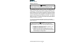
1
Index
GAS-FIRED COMMERCIAL WATER HEATER
A Spanish language version of these instructions is available by
contacting the company listed on the rating plate.
La versión espãnola de estas instructiones se puede obtener al
escrible a la fábrica cuyo nombre aparece en la placa de
especificaciones.
INSTALLATION &
OPERATING
INSTRUCTION MANUAL
WARNING: If the information in these instructions is not
followed exactly, a fire or explosion may result causing
property damage, personal injury or death.
FOR YOUR SAFETY
Do not store or use gasoline or other flammable,
combustible, or corrosive vapors and liquids in the
vicinity of this or any other appliance.
WHAT TO DO IF YOU SMELL GAS
• Do not try to light any appliance.
• Do not touch any electrical switch; do not use any
phone in your building.
• Immediately call your gas supplier from a neighbor’s
phone. Follow the gas supplier's instructions.
• If you cannot reach your gas supplier, call the fire
department.
Installation and service must be performed by a qualified
installer, service agency or the gas supplier.
For safety, convenience, and best performance, we recommend
this water heater be installed and serviced by a plumbing
professional.
238-39387-00H REV 7/00
TABLE OF CONTENTS
GENERAL INFORMATION............................................................
page
3
INSTALLATION. ............................................................................
5
Locating The Water Heater ....................................................
5
Minimum Clearances..............................................................
8
Venting..................................................................................... 14
Combustion Air Supply.......................................................... 16
Water Connections ................................................................. 18
Gas Connections .................................................................... 21
GENERAL OPERATION................................................................ 22
Wiring Diagrams
Standard Pilot Wiring Diagram. ....................................... 23
Spark Ignition Wiring Diagram. ....................................... 24
Lighting and Shutdown Instructions
Standard Pilot Models. ..................................................... 25
Spark Ignition Models. ..................................................... 26
Temperature Adjustment ....................................................... 27
Burner Flame Check............................................................... 29
MAINTENANCE ............................................................................. 30
OPERATING & TROUBLESHOOTING GUIDE............................. 34
TEMPERATURE CONTROL CHECKOUT .................................... 35
PARTS LIST & DRAWING ............................................................ 39
INSTALLATION INSTRUCTIONS FOR POTABLE WATER AND
SPACE HEATING .......................................................................... 40
NOTES ........................................................................................... 42
2
Index
GENERAL INFORMATION
This gas-fired water heater is design certified by the American Gas
Association Laboratories under the applicable American National Standard,
Z21.10.1 or Z21.10.3 (as indicated on the rating plate), available from the
American Gas Association, 1515 Wilson Blvd., Arlington, VA 22209.
The warranty for this water heater is in effect only when the water heater is
installed, adjusted, and operated in accordance with these Installation and
Operating Instructions. The warranty does not cover damage or injury caused
by the use of any energy-saving devices (other than those authorized by the
manufacturer) in conjunction with this water heater. The use of unauthorized
energy-saving devices may decrease the life of the water heater and
endanger life and/or property. The manufacturer will not be liable for any
damage, injury, or loss of life resulting from alteration and/or failure to comply
with these instructions.
This water heater has been equipped for use with one type of gas only.
Compare the information provided on the rating plate, affixed to the front of
the water heater, making sure that the gas stated on the rating plate is the
same as the gas to be used.
CAUTION
Do not attempt to use this water heater with any gas other than the type
listed on the rating plate. Do not attempt to convert this water heater
for use with a gas other than the type for which it is equipped. Failure to
use the proper gas can create an unsafe condition resulting in property
damage, bodily injury, or death. Consult your local gas supplier or gas
company if there are any questions.
This water heater must be installed in accordance with local codes. In the
absence of local codes, it must be installed in compliance with the National
Fuel Gas Code (ANSI Z223.1-Latest Edition), or in Canada CAN/CGA B149.1
Natural Gas Installation Code (Latest Edition) or CAN/CGA B149.2 Propane
Installation Code (Latest Edition).
For installations in high altitude regions, this water heater must be ordered
from the supplier to the manufacturer’s specifications for that particular
altitude. Contact the company listed on the rating plate when ordering high
altitude constructed water heaters.
This water heater has been designed and certified for the purpose of heating
potable water. The installation and use of this water heater for any purpose
other than the heating of potable water may cause damage to the water
heater, create a hazardous condition, and nullify the warranty.
General Information continued3
Index
CAUTION
Incorrect operation of this appliance may create a hazard to life and
property and will nullify the warranty.
DANGER
Do not store or use gasoline or other flammable, combustible, or
corrosive vapors and liquids in the vicinity of this or any other
appliance.
IMPORTANT
Before proceeding, please inspect the water heater and components for
possible damage. DO NOT install and damaged components. If damage
is evident then please contact the supplier where the water heater was
purchased or the manufacturer listed on the rating plate for replacement
parts.
4
Index
INSTALLATION
Locating The Water Heater
WARNING
Water heaters are heat producing appliances. To avoid damage or injury
there shall be no materials stored against the water heater and proper care
shall be taken to avoid unnecessary contact (especially by children) with
the water heater components. UNDER NO CIRCUMSTANCES SHALL
FLAMMABLE MATERIALS, SUCH AS GASOLINE OR PAINT THINNER
BE USED OR STORED IN THE VICINITY OF THIS WATER HEATER,
VENT-AIR INTAKE SYSTEM OR IN ANY LOCATION FROM WHICH
FUMES COULD REACH THE WATER HEATER OR VENT-AIR INTAKE
SYSTEM.
This water heater shall NOT be installed in any location where gasoline
or flammable vapors are likely to be present, unless the installation is
such to eliminate the probable ignition of gasoline or flammable vapors.
The location of this water heater is of the utmost importance. Before installing
this water heater, you should read the Installation section of these
instructions. After reading these Installation and Operating Instructions, select
a location for the water heater where the floor is level and is easily accessible
to water lines, gas supply (type identified on the rating plate), an adequate
open drain, and a chimney or exhaust gas vent. DO NOT locate the water
heater where water lines could be subjected to freezing temperatures.
Make sure the cold water pipes are not located directly above the gas
control so that condensate during humid weather does not drip on the
controls.
Adequate clearances shall be provided for easy access to controls by service
personnel to enable proper cleaning, servicing, and operation of the water
heater. Under no circumstances is the front of the water heater to be placed
in a position where the burner tray assembly can not slide out for removal
when servicing.
5
Index
Installation (Locating The Water Heater) continued-
Water heater corrosion and component failure can be caused by the heating
and breakdown of airborne chemical vapors. Examples of some
typical compounds that are potentially corrosive are: spray can propellants,
cleaning solvents, refrigerator and air conditioning refrigerants, swimming pool
chemicals, calcium and sodium chloride, waxes and process chemicals.
These materials are corrosive at very low concentration levels with little or no
odor to reveal their presence. NOTE: DAMAGE TO THE WATER HEATER
CAUSED BY EXPOSURE TO CORROSIVE VAPORS IS NOT COVERED
BY THE WARRANTY. DO NOT OPERATE THE WATER HEATER IF
EXPOSURE HAS OR WILL OCCUR. DO NOT STORE ANY POTENTIALLY
CORROSIVE COMPOUNDS IN THE VICINITY OF THE WATER HEATER.
WARNING
Liquefied petroleum gases/propane gas are heavier than air and will
remain at floor level if there is a leak. Basements, crawl spaces, closets
and areas below ground level will serve as pockets for accumulation of
leaking gas. Before lighting, smell all around the appliance area for gas.
Be sure to smell next to the floor.
IF YOU SMELL GAS:
• Do not try to light any appliance.
• Do not touch any electric switch; do not use any telephone in your
building.
• Immediately call your gas supplier from a telephone in another
building. Follow the gas supplier’s instructions.
• If you cannot reach your gas supplier, call the fire department.
DO NOT OPERATE APPLIANCE UNTIL LEAKAGE IS CORRECTED!
6
Index
Installation (Locating The Water Heater) continued-
WARNING
DO NOT ATTEMPT TO LIGHT ANY GAS APPLIANCE IF YOU ARE NOT
CERTAIN OF THE FOLLOWING:
• Liquefied petroleum gases/propane gas and natural gas have an
odorant added by the gas supplier that aids in detection of the gas.
• Most people recognize this odor as a “sulfur” or “rotten egg” smell.
• Other conditions, such as “odorant fade” can cause the odorant to
diminish in intensity, or “fade”, and not be as readily detectable.
• If you have a diminished sense of smell, or are in any way unsure of
the presence of gas, immediately contact your gas supplier from a
telephone in another building.
• Gas detectors are available. Contact your gas supplier or plumbing
professional for more information.
Proper venting practices must be considered when selecting a location for this
water heater. For exact venting specifications, please consult the Venting
section, located on page 10, of these Installation and Operating Instructions.
This water heater must be located in an area where leakage of the tank, water
line connections, or the combination temperature and pressure relief valve will
not result in damage to the area adjacent to the water heater or to lower floors
of the structure. When such locations cannot be avoided, a suitable drain pan
must be installed under the water heater. The drain pan must be no greater
than 1-½ inches (3.8 cm) deep and have a minimum length and width of at
least four (4) inches (10.2 cm) measured from the jacket of the water heater.
The drain pan, as described above, can be purchased from your plumbing
professional. The drain pan must be piped to an adequate drain. The piping
must be at least 3/4 inch (1.9 cm) in diameter and pitched for proper drainage.
It is recommended that a minimum clearance of four (4) inches (10.2 cm) be
provided on the side of the water heater for servicing and maintenance of the
combination temperature and pressure relief valve.
7
Index
Installation continued-
Minimum Clearances
WARNING
Failure to adhere to these installation and operating instructions may
create a hazard to life and property and will nullify the warranty.
This installation shall allow access to the front of the water heater and
adequate clearance shall be provided for servicing and operating this water
heater. The water heater may be installed on either a combustible or noncombustible floor. If the water heater is to be installed directly on carpeting, it
shall be installed on top of a metal or wood panel (or equivalent) extending
beyond the full width and depth of the appliance by at least three (3) inches
(7.6 cm) in any direction or, if the appliance is to be installed in an alcove or
closet, the entire floor shall be covered by the panel. The minimum
clearances to combustibles for this water heater are given in the tables on
pages 10 through 13. A minimum of 24 inches front clearance shall be
provided for inspection and servicing.
If it is necessary to install this water heater in an alcove on combustible
flooring with clearances from combustible materials as shown in the tables on
pages 10 through 13.
CAUTION
The National Fuel Gas Code (ANSI Z233.1-or latest edition) and
CAN/CGA (B149.1-or latest edition), expressly prohibits the following:
a) Installation of a water heater in a bathroom, bedroom, or any
occupied room normally kept closed.
b) Installation of a water heater in a garage, unless the unit is
installed so that the burner and ignition devices are at least
eighteen (18) inches (45.8 cm) above floor level and protected
to avoid damage by a moving vehicle.
Installation (Minimum Clearances) continued8
Index
Figure 1
Non-Flue Damper Models and Flue Damper Models
Model Description
Capacity Input (BTU/hr)
(GAL)
100
100
100
100
80
80
80
Nat.
199,999
250,000
270,000
300,000
399,999
450,000
505,000
LP
199,999
225,000
250,000
300,000
375,000
425,000
475,000
Model Description
Capacity
Input (kW/hr)
(Litres)
378.5
378.5
378.5
378.5
302.8
302.8
302.8
Nat.
58.7
73.3
79.3
88.0
117.3
131.9
148.0
LP
58.7
66.0
73.3
88.0
109.9
124.6
139.3
A
(in)
B
(in)
C
(in)
D
(in)
E
(in)
F
(in)
74.88
74.88
74.88
75.44
71.06
69.03
69.03
65.19
65.19
65.19
65.19
60.03
60.03
60.03
56.38
56.38
56.38
56.38
51.56
51.56
51.56
4.56
4.56
4.56
4.56
10.19
10.19
10.19
23
23
23
23
N/A
N/A
N/A
6
6
6
7
8
10
10
A
(m)
B
(m)
C
(m)
D
(cm)
1.90
1.90
1.90
1.92
1.81
1.75
1.75
1.66
1.66
1.66
1.66
1.53
1.53
1.53
1.43
1.43
1.43
1.43
1.31
1.31
1.31
11.6
11.6
11.6
11.6
25.9
25.9
25.9
1. N/A - Denotes not available.
Installation (Minimum Clearances) continued9
Clearances *
Sides Flue or Ceiling
(in)
and
Vent
Rear
(in)
(in)
2
6
20
2
6
20
2
6
20
2
6
20
6
6
20
6
6
20
6
6
20
Clearances *
Sides Flue or Ceiling
E
F
Vent
(cm)
(cm) (cm) and
Rear
(cm)
(cm)
58.4 15.2 5.1
15.3
50.8
58.4 15.2 5.1
15.3
50.8
58.4 15.2 5.1
15.3
50.8
58.4 10.2 5.1
15.3
50.8
N/A 10.2 15.3
15.3
50.8
N/A 25.4 15.3
15.3
50.8
N/A 25.4 15.3
15.3
50.8
Index
Figure 2
Non-Flue Damper Models
Model Designation
Capacity
Input
(GAL)
(BTU/hr)
65
65
75
80
80
370,000
399,999
(NAT ONLY)
300,000
425,000
505,000
Model Designation
Capacity
Input
(Litres)
(kW/hr)
246.1
246.1
283.9
302.8
302.8
108.5
117.3
(NAT ONLY)
88.0
124.6
148.0
Clearances *
Sides and Flue or Ceiling
Rear
Vent
(in.)
(in.)
(in.)
6
6
20
6
6
20
A
(in.)
B
(in.)
C
(in.)
D
(in.)
71.38
71.38
64.38
64.38
54.13
54.13
8
8
72.00
81.00
81.00
64.38
75.38
75.38
54.13
64.25
64.25
7
10
10
A
(m)
B
(m)
C
(m)
1.82
1.82
1.64
1.64
1.38
1.38
Clearances *
Sides and Flue or Ceiling
Rear
Vent
(cm)
(cm)
(cm)
20.4
15.3
15.3
50.8
20.4
15.3
15.3
50.8
1.83
2.06
2.06
1.64
1.92
1.92
1.38
1.64
1.64
17.8
25.4
25.4
Installation (Minimum Clearances) continued10
6
6
6
7
6
6
20
20
20
D
(cm)
15.3
15.3
15.3
17.8
15.3
15.3
50.8
50.8
50.8
Index
Flue Damper Models (Figure 2)
Model Designation
Capacity
Input
(GAL)
(BTU/hr)
65
65
370,000
399,999
(NAT ONLY)
300,000
425,000
505,000
75
80
80
Model Designation
Capacity
Input
(Litres)
(kW/hr)
246.1
246.1
283.9
302.8
302.8
108.5
117.3
(NAT ONLY)
88.0
124.6
148.0
Clearances *
Sides and Flue or Ceiling
Rear
Vent
(in.)
(in.)
(in.)
6
6
20
6
6
20
A
(in.)
B
(in.)
C
(in.)
D
(in.)
73.38
73.38
64.38
64.38
54.13
54.13
8
8
74.63
83.50
83.50
64.38
75.38
75.38
54.13
64.25
64.25
7
10
10
A
(m)
B
(m)
C
(m)
1.87
1.87
1.64
1.64
1.38
1.38
Clearances *
D
Sides and Flue or Ceiling
(cm)
Rear
Vent
(cm)
(cm)
(cm)
20.4
15.3
15.3
50.8
20.4
15.3
15.3
50.8
1.87
2.12
2.12
1.64
1.92
1.92
1.38
1.64
1.64
17.8
25.4
25.4
6
6
6
15.3
15.3
15.3
7
6
6
17.8
15.3
15.3
20
20
20
50.8
50.8
50.8
Figure 3
Flue Damper Models and Non-Flue Damper Models
Model Designation
Capacity
Input
(GAL)
(BTU/hr)
38
155,000
Model Designation
Capacity
Input
(Litres)
(kW/hr)
143.9
45.5
A
(in.)
B
(in.)
C
(in.)
D
(in.)
51.00
43.00
A
(m)
B
(m)
C
(m)
D
(m)
E
(cm)
1.30
1.10
0.88
0.86
15.3
34.75 33.75
Installation (Minimum Clearances) continued11
E
(in.)
6
Clearances *
Sides and
Flue or
Rear
Vent
(in.)
(in.)
2
6
Clearances *
Sides and
Flue or
Rear
Vent
(cm)
(cm)
5.1
15.3
Ceiling
(in.)
20
Ceiling
(cm)
50.8
Index
Figure 4
Non-Flue Damper Models
Model Designation
Capacity
Input
(GAL)
(BTU/hr)
80
80
80
98
98
100
100
180,000
199,999
(235,000 LP)
250,000
(235,000 LP)
199,999
250,000
(235,000 LP)
199,999
250,000
Model Designation
Capacity
Input
(Liters)
(kW/hr)
302.8
302.8
302.8
371.0
371.0
378.5
378.5
52.8
58.7
(68.9 LP)
73.3
(68.9 LP)
52.8
73.3
(68.9 LP)
52.8
73.3
A
(in.)
B
(in.)
70.13
70.13
66.25
66.25
Clearances *
Sides and
Flue or
Rear
Vent
(in.)
(in.)
64.38 56.00 55.13
2
6
64.38 56.00 55.13
2
6
70.13
66.25
64.38 56.00 55.13
2
6
20
81.13
82.88
77.25
77.25
75.38 67.00 66.13
75.38 67.00 66.13
2
2
6
6
20
20
75.50
75.50
69.88
69.88
61.88 60.38 56.88
61.88 60.38 56.88
2
2
6
6
20
20
A
(m)
B
(m)
C
(m)
D
(m)
E
(m)
1.79
1.79
1.69
1.69
1.64
1.64
1.43
1.43
1.40
1.40
1.79
1.69
1.64
1.43
1.40
5.1
15.3
50.8
2.06
2.11
1.97
1.97
1.92
1.92
1.71
1.71
1.68
1.68
5.1
5.1
15.3
15.3
50.8
50.8
1.92
1.92
1.78
1.78
1.58
1.58
1.54
1.54
1.45
1.45
5.1
5.1
15.3
15.3
50.8
50.8
C
(in.)
D
(in.)
Installation (Minimum Clearances) continued12
E
(in.)
Clearances *
Sides and
Flue or
Rear
Vent
(cm)
(cm)
5.1
15.3
5.1
15.3
Ceiling
(in.)
20
20
Ceiling
(cm)
50.8
50.8
Index
Flue Damper Models (Figure 4)
Model Designation
Capacity
Input
(GAL)
(BTU/HR)
80
80
80
98
98
100
100
180,000
199,999
(235,000 LP)
250,000
(235,000 LP)
199,999
250,000
(235,000 LP)
199,999
250,000
Model Designation
Capacity
Input
(Liters)
(kW/hr)
302.8
302.8
302.8
371.0
371.0
378.5
378.5
52.8
58.7
(68.9 LP)
73.3
(68.9 LP)
52.8
73.3
(68.9 LP)
52.8
73.3
A
(in.)
B
(in.)
71.88
71.88
66.25
66.25
Clearances *
Sides and
Flue or
Rear
Vent
(in.)
(in.)
64.38 56.00 55.13
2
6
64.38 56.00 55.13
2
6
71.88
66.25
64.38 56.00 55.13
2
6
20
82.88
82.88
77.25
77.25
75.38 67.00 66.13
75.38 67.00 66.13
2
2
6
6
20
20
75.50
75.50
69.88
69.88
61.88 60.38 56.88
61.88 60.38 56.88
2
2
6
6
20
20
A
(m)
B
(m)
C
(m)
D
(m)
E
(m)
1.83
1.83
1.69
1.69
1.64
1.64
1.43
1.43
1.40
1.40
1.83
1.69
1.64
1.43
1.40
5.1
15.3
50.8
2.11
2.11
1.97
1.97
1.92
1.92
1.71
1.71
1.68
1.68
5.1
5.1
15.3
15.3
50.8
50.8
1.92
1.92
1.78
1.78
1.58
1.58
1.54
1.54
1.45
1.45
5.1
5.1
15.3
15.3
50.8
50.8
C
(in.)
D
(in.)
E
(in.)
Clearances *
Sides and
Flue or
Rear
Vent
(cm)
(cm)
5.1
15.3
5.1
15.3
Ceiling
(in.)
20
20
Ceiling
(cm)
50.8
50.8
The following notes apply to the tables accompanying Figures 1 - 4.
1. All models with flue dampers and/or above 400,000 BTU per hour
input employ a “spark” (IID) ignition system and requires 120 volt AC
electric supply.
2. * -Denotes minimum clearances to combustible material. Some
models may have different clearances. Check the label on the front of
the water heater to verify proper installation clearances.
3. Model number may have a suffix “N” for natural gas or “X”, “P” or “L”
for liquefied petroleum (LP) gases. Some models may have “A” as a
suffix or prefix. Check the rating plate on front of the water heater for
model number verification.
Installation continued13
Index
Venting
WARNING
The vent system must be installed properly. Failure to properly install the
vent system could result in property damage, personal injury, or death.
This water heater has been shipped with a draft diverter for which it was
designed with reference to the horizontal and vertical planes. If removed, the
draft diverter shall be replaced in the same position and secured to the jacket
top by the screws with which it was installed.
This water heater must be connected to a masonry chimney or venting system
approved by local codes or ordinances. The vent connector used to attach
the draft diverter outlet to the chimney or approved vent must be of the same
diameter as the draft diverter outlet or larger. For proper venting in certain
installations, a larger vent connector may be needed. Consult venting tables
in ANSI standard (Z223.1-or latest edition), National Fuel Gas Code and
CAN/CGA (B149.1 or B149.2-latest editions), or local code officials for proper
application for your area.
Flue Damper
Refer to Figure 5 and follow these instructions:
CAUTION
Do not turn on electrical power to water heater until flue damper is
installed and water heater is filled with water.
1. Remove the damper from the accompanying box shipped within the crate.
2. Locate the collector outlet on top of the water heater. Place the damper
over the collector outlet and rotate as necessary to a position in which the
damper wiring plug can be fully engaged with the connector on the side of
the water heater.
3. Remove clip which holds damper vane closed. If supplied this type of vent
damper will then open by itself.
4. Being certain that the damper vane will travel freely from the “closed” to
“open” position, secure the flue damper to the jacket top with sheet metal
screws. Note: Some dampers require an additional bracket to assure level
installation.
Installation (Venting) continued14
Index
5. Connect the damper wiring plug to the connector on the side of the water
heater. Note: The plug and connector can only be engaged one way
(polarized).
6. The Lighting and Operating instructions are outlined beginning on
page 25. The damper must be in the open position when the water heater
main burner is operating (the arrow on the damper plate is in the “up”
position when open. Be certain the arrow is in a visible position when
installed).
CAUTION
Modification to the flue damper or the draft diverter may result in
personal injury, property damage or death. The flue damper and
draft diverter are to be placed in position and operate exactly as
stated in these instructions without modification.
Combustion Air Supply
15
Index
WARNING
Liquefied petroleum gases/propane gas are heavier than air and will
remain at floor level if there is a leak. Basements, crawl spaces, closets
and areas below ground level will serve as pockets for accumulation of
leaking gas. Before lighting, smell all around the appliance area for gas.
Be sure to smell next to the floor.
IF YOU SMELL GAS:
• Do not try to light any appliance.
• Do not touch any electric switch; do not use any telephone in your
building.
• Immediately call your gas supplier from a telephone in another
building. Follow the gas supplier’s instructions.
• If you cannot reach your gas supplier, call the fire department.
DO NOT OPERATE APPLIANCE UNTIL LEAKAGE IS CORRECTED!
IMPORTANT
The flow of combustion and ventilating air must not be obstructed.
Provide adequate air for combustion and ventilation. An insufficient supply of
air will cause recirculation of combustion products resulting in air
contamination that may be hazardous to life. Such a condition often will result
in a yellow, luminous burner flames, causing carboning or sooting of the
burners and flue tubes with possible damage to the heater.
Confined Spaces
If the water heater is installed in a confined space (volume is less than 50
ft.3/1000 BTU (15 m3/0.29 kW) per hour of the total input rating of all gas
appliances in that space), air must be supplied through two permanent
openings. One opening shall be within 12 inches (30.5 cm) from the top of the
enclosure and one within 12 inches (30.5 cm) of the bottom. The openings
must be protected by metal louvers or 1/4” (6.4 mm) min. mesh metal screen.
The size of the openings are as follows.
1. If the openings communicate directly with an additional room(s) of
sufficient volume, each opening shall have a minimum free area opening of
1 in.2/1000 BTU (2.54cm2/0.29kW) per hour of the total input rating of all
gas appliances in the confined space, but not less than 100 in.2 (254 cm2).
Installation (Combustion Air Supply) continued-
16
Index
2. If the openings communicate with the outdoors through horizontal ducts,
each opening shall have a minimum free area of 1 in.2/2000 BTU
(2.54cm2/0.59kW) per hour of the total rating of all gas appliances in the
enclosure.
3. If the openings communicate directly with the outdoors or through vertical
ducts with the outdoors, each opening shall have a minimum free area of
1 in.2 /4000 BTU (2.54cm2/1.18kW) per hour of the total rating of all gas
appliances in the enclosure.
CAUTION
The draft diverter relief opening of the water heater and combustion
air inlet must be in the same atmospheric pressure zone. Large
exhaust fans in kitchens and other locations can lower the air
pressure inside an enclosure and interfere with the proper operation
and venting of the water heater . In these cases, the water heater
should be installed in a separate room with the combustion and
ventilation air supplied directly from outdoors as previously
described.
All Air From Inside the Building: The confined space shall be provided with
two permanent openings communicating directly with an additional room(s) of
sufficient volume so that the combined volume of all spaces meets the criteria
for an unconfined space. The total input of all gas utilization equipment
installed in the combined space shall be considered in making this
determination. Each opening shall have a minimum free area of 1 in.2/1000
BTU (2.54cm2/0.29kW) per hour of the total input rating of all gas utilization
equipment in the confined space, but not less than 100 square inches
(254cm2). One opening shall be within 12 inches (30.5 cm) of the top and one
within 12 inches (30.5 cm) of the bottom of the enclosure.
Unconfined Spaces
In unconfined spaces in buildings, infiltration may be adequate to provide air
for combustion, ventilation and dilution of flue gases. However, in buildings of
tight construction (for example, weather stripping, heavily insulated, caulked,
vapor barrier, etc.), additional air may need to be provided using the methods
described above under CONFINED SPACES: All Air From Outdoors or
SPECIALLY ENGINEERED INSTALLATIONS.
Specially Engineered Installations
The requirements noted under CONFINED SPACES above shall not
necessarily govern when special engineering, approved by the authority
having jurisdiction, provides an adequate supply of air for combustion,
ventilation, and dilution of flue gases.
Water Connections
17
Index
Note: BEFORE PROCEEDING WITH THE INSTALLATION, CLOSE THE
MAIN WATER SUPPLY VALVE.
After shutting off the main water supply, open a faucet to relieve the water line
pressure to prevent any water from leaking out of the pipes while making the
water connections to the water heater. After the pressure has been relieved,
close the faucet. The COLD water inlet and HOT water outlet are identified on
the top and front of the water heater. Make sure the diptube is in place before
making the cold water connection. Make the proper plumbing connections
between the water heater and the plumbing system to the house. Install a
shut-off valve in the cold water supply line.
CAUTION
If sweat fittings are to be used, DO NOT apply heat to the nipples on top or
side of the water heater. Sweat the tubing to the adapter before fitting the
adapter to the water connections. It is imperative that heat is not applied to
the nipples containing a plastic liner.
WARNING
FAILURE TO INSTALL AND MAINTAIN A NEW, LISTED
TEMPERATURE AND PRESSURE RELIEF VALVE WILL RELEASE
THE MANUFACTURER FROM ANY CLAIM WHICH MIGHT RESULT
FROM EXCESSIVE TEMPERATURE AND PRESSURES.
If this water heater is installed in a closed water supply system, such as the
one having a back-flow preventer in the cold water supply, provisions shall be
made to control thermal expansion. DO NOT operate this water heater in a
closed system without provisions for controlling thermal expansion.
Warranties do not cover damages from thermal expansions such as pressure
bulges and/or deformities. Your water supplier or local plumbing inspector
should be contacted on how to control this situation
After installation of the water lines, open the main water supply valve and fill
the water heater. While the water heater is filling, open several hot water
faucets to allow air to escape from the water system. When a steady stream
of water flows through the faucets, close them and check all water
connections for possible leaks. NEVER OPERATE THE WATER HEATER
WITHOUT FIRST BEING CERTAIN IT IS FILLED WITH WATER.
CAUTION
Keep clear of combination temperature and pressure relief valve
discharge line outlet. The discharge may be hot enough to cause scald
injury. The water is under pressure and may splash.
18
Index
WARNING
For protection against excessive temperatures and pressure, install
temperature and pressure protective equipment required by local codes,
but not less than a combination temperature and pressure relief valve
certified by a nationally recognized testing laboratory that maintains
periodic inspection of production of listed equipment or materials as
meeting the requirements of the Standard for Relief Valves and Automatic
Gas Shutoff Devices for Hot Water Supply Systems, ANS Z21.22 and the
Standard CAN1-4.4 Temperature, Pressure, Temperature and Pressure
Relief Valves and Vacuum Relief Valves. The combination temperature
and pressure relief valve shall be marked with a maximum set pressure
not to exceed the maximum working pressure of the water heater. The
combination temperature and pressure relief valve shall also have an
hourly rated temperature steam BTU discharge capacity not less than the
hourly rating of the water heater.
Install the combination temperature and pressure relief valve into the
opening provided and marked for this purpose on the water heater.
Note: Some models may already be equipped or supplied with a
combination temperature and pressure relief valve. Verify that the
combination temperature and pressure relief valve complies with local
codes. If the combination temperature and pressure relief valve does not
comply with local codes, replace it with one that does. Follow the
installation instructions above on this page.
Install a discharge line so that water discharged from the combination
temperature and pressure relief valve will exit within six (6) inches (15.2
cm) above, or any distance below the structural floor and cannot contact
any live electrical part. The discharge line is to be installed to allow for
complete drainage of both the combination temperature and pressure
relief valve and the discharge line. The discharge opening must not be
subjected to blockage or freezing. DO NOT thread, plug or cap the
discharge line. It is recommended that a minimum clearance of four (4)
inches (10.2 cm) be provided on the side of the water heater for servicing
and maintenance of the combination temperature and pressure relief
valve.
Do not place a valve between the combination temperature and pressure
relief valve and the tank.
Installation (Water Connections) continued19
Index
WARNING
Hydrogen gas can be produced in an operating water heater that has
not had water drawn from the tank for a long period of time (generally
two weeks or more). Hydrogen gas is extremely flammable. To
prevent the possibility of injury under these conditions, we
recommend the hot water faucet to be open for several minutes at the
kitchen sink before you use any electrical appliance which is
connected to the hot water system. If hydrogen is present, there will
be an unusual sound such as air escaping through the pipes as hot
water begins to flow. Do not smoke or have open flame near the
faucet at the time it is open.
This water heater can deliver scalding temperature water at any faucet in the
system. Be careful whenever using hot water to avoid scalding injury. Certain
appliances such as dishwashers and automatic clothes washers may require
increased temperature water. By setting the thermostat on this water heater
to obtain the increased temperature water required by these appliances, you
may create the potential for scald injury. To protect against injury, you should
install an anti-scald tempering valve in the water system. This valve will
reduce point of discharge temperature by mixing cold and hot water in branch
supply lines. Such valves are available from the local plumbing supplier.
Please consult with a plumbing professional. For information regarding space
heating water connections and plumbing arrangements, refer to page 40.
Gas Connections
20
Index
The gas supply lines must meet all requirements of the National Fuel Gas
Code (ANSI Z223.1-Latest Edition), or in Canada CAN/CGA B149.1 Natural
Gas Installation Code (Latest Edition) or CAN/CGA B149.2 Propane
Installation Code (Latest Edition).
The minimum permissible gas supply pressure for the purpose of input
adjustment is one (1.0) inch (0.25 kPa) water column above the operating
manifold pressure. See the rating plate and gas valve for the manifold
pressure and gas type. The maximum permissible gas supply pressure is
fourteen (14.0) inches (3.5 kPa) water column for natural gas and liquefied
petroleum gases/propane gas.
1. Connect this water heater only to the type of gas (Natural or Propane gas)
as shown on the rating plate. Use clean black iron pipe or equivalent
material approved by local codes and ordinances. (Dirt and scale from the
pipe can enter the gas valve and cause it to malfunction). The inlet gas
line must have a minimum length of three (4) inches (7.6 cm) drip leg
(sediment trap) installed as close to the water heater’s gas valve as
possible. A ground joint union must be installed in the gas supply line, as
close to the water heater as possible, feeding the water heater to permit
servicing of the water heater. Compounds used on the threaded joints of
the gas piping must be resistant to the action of liquefied petroleum
gases/propane gas. DO NOT apply pipe dope to the gas valve inlet and
make certain that no pipe dope has become lodged in the inlet screen of
the gas valve. Extreme care shall be taken to ensure no pipe dope enters
the gas valve and to avoid excessive torque when tightening the gas
supply line to the gas valve. Excessive torque may result in cracking of
the gas valve housing. The suggested maximum torque is 31.5 ft. lbs.
(4.4 kg-m). The manufacturer of this water heater will not be liable for any
damage or injury caused as a result of a cracked gas inlet as a result of
excessive torque.
2. This water heater and its gas connection must be leak tested before
placing the water heater in operation. Check for gas leaks with a soap
and water solution and a brush or a commercial leak detector fluid.
NEVER USE A MATCH OR OPEN FLAME FOR TESTING!
CAUTION
The water heater and individual shutoff valve must be disconnected from
the gas supply piping system during any pressure testing of the system at
test pressures in excess of 1/2 psi (3.5 kPa). The water heater must be
isolated from the gas supply piping system by closing its manual shutoff
valve during any pressure testing of the gas supply system at test
pressures equal to or less than 1/2 psi (3.5 kPa). The supply line must be
capped when not connected to the water heater.
GENERAL OPERATION
21
Index
WARNING
Water heaters are heat producing appliances. To avoid damage or injury
there shall be no materials stored against the water heater or vent-air intake
system, and proper care shall be taken to avoid unnecessary contact
(especially by children) with the water heater and vent-air intake system.
UNDER NO CIRCUMSTANCES SHALL FLAMMABLE MATERIALS,
SUCH AS GASOLINE OR PAINT THINNER BE USED OR STORED IN
THE VICINITY OF THIS WATER HEATER OR IN ANY LOCATION FROM
WHICH FUMES COULD REACH THE WATER HEATER.
TO FILL THE WATER HEATER
1. Close the water heater drain valve by turning the knob clockwise. If
alternative water connections are provided but not used, make certain
they are plugged (i.e. rear connections).
2. Open the cold water supply shut-off valve.
3. Open several hot water faucets to allow air to escape from the system.
4. When a steady stream of water flows from the faucets, the water heater is
filled. Close the faucets and check for water leaks at the water heater
drain valve, combination temperature and pressure relief valve and the
hot and cold water connections.
TO DRAIN THE WATER HEATER
Should it become necessary to completely drain the water heater, make sure
you follow the steps below:
1. Rotate the thermostat dial clockwise to the “PILOT LIGHTING” position.
2. Rotate and partially depress gas control knob clockwise to the “OFF”
position.
3. Shut off the gas supply to the water heater.
4. Close the cold water supply shut-off valve.
5. Open the drain valve on the water heater by turning the knob counterclockwise. The drain valve has threads on the end that will allow the
connection of a standard hose coupling.
6. Open a hot water faucet to allow air to enter the system.
To refill the water heater, refer to “To Fill the Water Heater.”
General Operation (Standard Pilot Wiring Diagram) continued-
22
Index
General Operation (Spark Ignition Wiring Diagram) continued-
23
Index
Lighting And Shutdown Instructions
24
Index
Standard Pilot Models
General Operation (Lighting and Shutdown) continued25
Index
Spark Ignition Models
General Operation continued26
Index
Temperature Adjustment
The temperature selector knob of the thermostat has been adjusted to its
lowest setting when shipped from the factory.
The detent on the thermostat temperature scale (shown below) is the
preferred starting point for setting the temperature control. For energyefficient operation of your water heater, the suggested initial temperature
setting is approximately 130°F (55°C). Households with small children or
invalids may require a 120°F (49°C) or lower temperature setting to reduce
the risk of scald injury. Some states require a lower temperature setting. Full
rotation of the temperature selector knob is the
counterclockwise
minimum temperature setting. Full clockwise
rotation of the
temperature selector knob is the maximum temperature setting. NOTE: The
lower the temperature setting, the greater the energy efficiency, both to heat
the water and to maintain its temperature during standby periods. Lower
water temperatures also extend tank life. Remember, no water heating
system will provide exact temperatures at all times. Allow a few days of
operation at this setting to determine the correct temperature setting
consistent with your needs. NOTE: This water heater, when set at a lower
temperature setting, is not capable of producing hot water of sufficient
temperature for sanitizing purposes.
During winter season or any cold period, you may desire a higher temperature
setting to adjust for the colder incoming water. This adjustment, however,
may cause additional condensation to form on the cooler tank surface. This
does not mean the tank is leaking. During summer months, the warmer
incoming water temperatures will benefit the performance of your water heater
and reduce the amount of condensation developed.
Condensation does not mean your tank is leaking. Over 40% of reported tank
leaks on installation are proven to be condensation. To avoid unnecessary
expense and inconvenience, make sure the tank is leaking before calling a
service person.
Figure 5
27
Index
General Operation (Temperature Adjustment) continued-
DANGER
Hotter water increases the risk of scald injury. Scalding may occur
within five (5) seconds at a temperature setting of 135°F (57°C). To
protect against hot water injury, install an anti-scald tempering valve in
the water system. This valve will reduce point of discharge temperature
by mixing cold and hot water in branch water lines. A licensed plumbing
professional or local plumbing authority should be consulted.
Note: This water heater is equipped with an energy cut out device to
prevent overheating. Should overheating occur or the gas supply fail to
shut off, turn off the manual gas control valve to the appliance and call a
qualified service technician.
Note: Whenever the water heater is filled with cold water, condensate
will form on the cool tank surface and drops of water will fall on the hot
burner and combustion chamber surfaces producing a “sizzling” noise.
Condensation is normal and does not indicate a leak. It will disappear
when the tank becomes heated.
An automatic gas shut-off device (ECO) is incorporated in the thermostat
which will shut off all gas supply to the burner and pilot if the water heater
temperature exceeds 200°F (93°C). Should the ECO function (open), the
water temperature should be reduced to approximately 120°F (49°C) and
follow applicable Lighting Instructions (page 25 or 26) to place the water
heater in operation. If a problem exists, contact your dealer for service. It is
recommended that all service work be performed by a qualified service
agency.
If the water heater is to remain idle for 30 days or more or is subjected to
freezing temperatures while shut off, the water heater and piping should be
fully drained (See page 22, “To Drain the Water Heater”) and the drain valve
should be left fully open.
WARNING
Hydrogen gas can be produced in an operating water heater that has
not had water drawn from the tank for a long period of time (generally
two weeks or more). Hydrogen gas is extremely flammable. To
prevent the possibility of injury under these conditions, we
recommend the hot water faucet to be open for several minutes at the
kitchen sink before you use any electrical appliance which is
connected to the hot water system. If hydrogen is present, there will
be an unusual sound such as air escaping through the pipes as hot
water begins to flow. Do not smoke or have open flame near the
faucet at the time it is open.
28
Index
General Operation continued-
Burner Flame Check
At the time of installation and at periodic intervals (about every 3 months), a
visual check of the pilot and burner flames should be made to determine if
they are burning properly. No adjustment to the air shutter is required for this
heater. The burner flames should be blue with yellow tips. A blue-orange
flame is characteristic of operation on liquefied petroleum (LP) gas. The
burner tube flames should light smoothly from the pilot.
IMPORTANT
In the event of an emergency, turn off the gas and electric (if applicable) to
the appliance.
Figure 6
29
Index
MAINTENANCE
WARNING
Water heaters are heat producing appliances. To avoid damage or injury
there shall be no materials stored against the water heater or vent system,
and proper care shall be taken to avoid unnecessary contact (especially by
children) with the water heater and vent system. UNDER NO
CIRCUMSTANCES SHALL FLAMMABLE MATERIALS, SUCH AS
GASOLINE OR PAINT THINNER BE USED OR STORED IN THE
VICINITY OF THIS WATER HEATER, VENT SYSTEM OR IN ANY
LOCATION FROM WHICH FUMES COULD REACH THE WATER
HEATER OR VENT SYSTEM.
IMPORTANT
The water heater should be inspected at a minimum annually by a
qualified service technician for damaged components and/or joints
not sealed. DO NOT operate this water heater if any part is found
damaged or if any joint is found not sealed.
The following maintenance should be performed by a qualified service
technician at the minimum periodic intervals suggested below. In some
installations, the maintenance interval may be more frequent depending on
the amount of use and the operating conditions of the water heater. Regular
inspection and maintenance of the water heater will help to insure safe and
reliable operation.
1. Annual checks of the ignition systems (millivolt and electronic),
temperature controls and any other water heater controls are necessary
to ensure proper operation. Also, all safety shut-off valves must be
checked to verify proper operation and tightness.
2. The flow of combustion and ventilation air MUST NOT be restricted.
Clear the combustion air openings of any dirt, dust, or other restrictions.
WARNING! The ventilation air system may be HOT.
3. At all times keep the water heater area clear and free from combustible
materials, gasoline and other flammable vapors and liquids.
4. Bi-annually conduct a visual check of the pilot and burner flames to
determine that they are burning properly. See “Burner Flame Check”
section on page 29 for example of proper burner flame pattern.
Maintenance continued30
Index
5. Annually remove the main burner rack assembly to clean orifices and
related parts of any dirt or other foreign material. Inspect the burner ports
for obstructions or debris and clean with a wire brush, vacuum, or use a
mild detergent solution to clean as needed. NOTE: It is imperative for
proper operation of the water heater that the main burner rack be
replaced in the original location.
WARNING
When lifting lever of the combination temperature and pressure relief
valve, hot water will be released under pressure. Be careful that any
released water does not result in bodily injury or property damage.
7. At least once a year, check the combination temperature and pressure
relief valve to insure that the valve has not become encrusted with lime.
Lift the lever at the top of the valve several times until the valve seats
properly without leaking and operates freely.
8. Monthly drain off a gallon of water to remove silt and sediment.
WARNING! THIS WATER MAY BE HOT.
9. If the combination temperature and pressure relief valve on the appliance
discharges periodically, this may be due to thermal expansion in a closed
water supply system. Contact the water supplier or local plumbing
inspector on how to correct this situation. Do not plug the combination
temperature and pressure relief valve outlet.
10. All models are equipped with a cleanout opening to aid in removal of hard
water deposits from the tank bottom. If this water heater operates under
hard water conditions, the following should be performed at least every 3
months: Drain the water heater. Remove the cleanout jacket cover and
tank cover. When cleaning the tank, care must be taken to avoid trying to
break deposits loose as this could damage the glass lining and shorten
the life of the water heater. After cleaning, replace the cleanout tank
cover and jacket cover, and refill with water.
11. A combination sacrificial anode rod/hot water outlet nipple has been
installed to extend tank life. The anode rod should be inspected
periodically (every 2 years) and replaced when necessary to prolong tank
life. Water conditions in your area will influence the time interval for
inspection and replacement of the anode rod. Contact the plumbing
professional who installed the water heater or the manufacturer listed on
the rating plate for anode replacement information. The use of a water
softener may increase the speed of anode consumption. More frequent
inspection of the anode is needed when using softened (or phosphate
treated) water.
31
Index
Maintenance (continued)-
CAUTION
FOR YOUR SAFETY, DO NOT ATTEMPT REPAIR OF COMBINATION
GAS CONTROL, BURNERS OR GAS PIPING. REFER REPAIRS TO A
QUALIFIED SERVICE TECHNICIAN.
Contact your supplier, plumbing professional or contact the company at the
address given on the rating plate of the water heater for replacement parts.
Provide the part name as well as the model and serial number(s) of the water
heater(s) when ordering parts.
READ THE WARRANTY FOR A FULL EXPLANATION OF THE LENGTH
OF TIME THAT PARTS AND THE WATER HEATER ARE WARRANTED.
Manufactured under one or more of the following U.S. Patents: Re. 34,534;
4,416,222; 4,628,184; 4,669,448; 4,672,919; 4,808,356; 4,829,983; 4,861,968;
4,904,428; 5,000,893; 5,023,031; 5,052,346; 5,081,696; 5,092,519; 5,115,767;
5,199,385; 5,277,171; B1 5,341,770; 5,372,185; 5,485,879; 5,574,822; 5,596,952;
5,660,165; 5,682,666; 5,761,379; 5,943,984; 5,954,492; 5,988,117. Other U.S. and
Foreign patents applications pending. Current Canadian Patents: 1,272,914;
1,280,043; 1,289,832; 2,045,862; 2,112,525.
Complete the following information and retain for future reference:
Model No:
Serial No:
Service Phone
Days:
Nights:
Address:
Supplier:
Supplier Phone No:
TYPICAL INSTALLATION
32
Index
Operating and Troubleshooting Guide - Sequence of Normal
Operation (Electronic Thermostat with Intermittent Pilot Ignition)
33
Index
1. The electronic thermostat controls the 24-volt circuit to the ignition control.
When the thermostat contacts close, a 24-volt circuit is completed from the
transformer through the thermostat relay to the ignition control module to
initiate the ignition sequence.
2. On flue damper models, the damper reaches then full open position, the
end switches in the damper close, completing the 24-volt circuit to the
ignition module.
3. The ignition control sends 24-volt power to the pilot valve “PV” terminals on
the gas valve allowing pilot gas to flow to the pilot. The ignition control also
simultaneously sends high voltage low current electricity through the
electrode wire to the pilot electrode causing sparks at the pilot electrode to
ignite the pilot gas. If the pilot fails to ignite within 90 seconds, the ignition
control stops the pilot gas and sparking for 15 seconds to allow gas to
dissipate. The ignition control will then attempt 2 (two) more ignition trials
as stated above. If the pilot does not ignite after 3 trials, the ignition control
will then go into “lockout mode”, and the ignition system will remain shut
down until the control is reset by interrupting power to the ignition module.
4. When the pilot gas ignites, the flame is sensed by the electrode or a flame
sensing rod. The flame sensing signal received by the ignition control
causes the sparking to stop and the main gas valve to open. The main
burners ignite from the pilot flame. The pilot flame is continually monitored
by the flame sensing circuit. If for any reason, the pilot flame is not sensed
by the electrode or flame sensing rod, the main gas valve closes, the spark
electrode is reenergized, and the ignition trial period is reestablished. The
same sequence occurs during a power or gas supply interruption.
5. The main burners continue to operate until the water temperature in the
tank increases enough to cause the thermostat contacts to open. When
the thermostat contacts open the 24-volt power is interrupted to the ignition
control module and the gas valve closes. The flue damper (on “D” models)
closes.
6. If for some reason thermostat contacts fail to open, then the high
temperature limit (ECO) contacts in the thermostat sensor open and
interrupts power to the pilot valve causing the pilot to extinguish. The
ignition module senses the pilot outage and attempts to relight the pilot by
reestablishing the sparking at the electrode as stated in paragraph 3
above. Since the pilot valve circuit is open, the pilot will not ignite and the
system will go into “lockout mode” after 3 ignition trials. In the “lockout
mode”, the ignition system will remain shutdown until the control is reset by
interrupting power to the ignition module. The ECO will not reset to close
the contacts until the tank water temperature drops to between 100°F
(38°C) and 160°F (71°C). If the ECO contacts open, the cause for the high
water temperature should be determined before resetting the ignition
system.
Troubleshooting Procedure for Electronic Thermostat
If water temperature is too hot, proceed as follows:
34
Index
Test or Condition:
Result:
Action Taken:
Start - Disconnect sensor
leads from electronic control
module and measure
resistance of sensor(s) with
ohmmeter
Sensors O.K. Disconnect
ECO leads and measure
resistance with ohmmeter
Is resistance between 700 and
30K ohms (see page 38)?
YES↓
NO→
Sensor(s) may be shortened
or open. Check for loose,
broken or shorted wires.
Replace sensing bulb(s) if
necessary.
Replace sensing bulb with
ECO limit and check out
balance of system.
Disconnect potentiometer
leads from electronic control
module. Measure resistance
of potentiometer with
ohmmeter.
Potentiometer O.K.
Is water temperature greater
than 210°F (99°C) and ECO
resistance less than 10 ohms
(shorted)?
YES→
NO↓
Is resistance greater than
4800 ohms at minimum
temperature setting (checks
for short)?
YES↓
NO→
Replace electronic control
module. Reconnect all leads
and check out system
Replace electronic control
module. Reconnect all leads
and check out system
If water temperature is too cold or heater does not come on, proceed as
follows:
Test or Condition:
Result:
Action Taken:
Start: Check voltage at 24-volt
terminals of electronic control
module of thermostat board.
Are main burners operating or
is pilot trying to light
(sparking)?
YES↓
NO→
Is voltage between 21.5 and
28.5 VAC?
YES↓
NO→
Check for voltage at N.O.
thermostat terminals (terminal
to meter to ground). Is voltage
between 21.5 and 28.5 VAC?
YES↓
NO→
Check power supply,
transformer. Correct as
necessary.
Thermostat relay is not
closing. Check thermostat
setting. Refer to thermostat
troubleshooting below.
Troubleshooting Procedure for Electronic Thermostat (continued)-
If water temperature is too cold or heater does not come on, proceed as
follows:
35
Index
Test or Condition:
Result:
Action Taken:
Are burners operating?
If pilot does not light and pilot is
not sparking, check to make sure
flue damper is in the full open
position. Damper opens?
YES↓
NO→
Check flue damper wiring.
Check for 24 volts at yellow wire
from thermostat to damper. If
damper still does not open check
for 24 volts between red and
white wires to damper. If damper
does not open when voltage is
present and thermostat is closed,
replace damper operator.
Check black wire from damper
for 24 volts to ground. If no
voltage is present, but damper is
open and voltage is present
between yellow wire and ground,
end switch in damper may be
faulty. Replace damper operator.
If the pilot valve will not open
when voltage is present to the to
the PV terminal and the common
terminal “PV/MV” wire has
continuity to the module, the gas
valve may be defective. If no
voltage is present at “PV” on the
ignition control and the ECO is
closed (power to 24V and 24V
GND terminals of module) the
ignition control module may be
defective. Replace and recheck
system.
Make sure pilot flame is steady
and envelopes the electrode or
flame sensor. Turn pilot
adjustment screw counterclockwise to increase size of pilot
flame. Make sure pilot shield is
in place.
If damper opens, but pilot does
light or spark:
Does pilot spark without lighting
pilot? Make sure there is
sufficient gas pressure at the gas
valve inlet. Check the nameplate
for minimum gas supply
pressures for the type of gas
used. Check for plugged pilot
orifice.
Check gas valve by measuring
voltage from “PV” to ground. If
no voltage, check continuity
across ECO circuit of thermostat
(red wires). If ECO is open, it
should reset after tank cools
below 160°F (71°C). If it does
not reset, replace sensing bulb
with the ECO. If ECO has
opened, there may be a problem
with the thermostat.
Pilot lights, but main gas does
not come on.
If pilot flame is stable, check for
voltage at the “MV” terminal at
the ignition module and gas
valve. If no voltage is present at
the ignition module, replace
control. If voltage is present at
the gas valve, replace valve.
Troubleshooting Procedure for Electronic Thermostat (continued)-
If water temperature is too cold or heater does not come on, proceed as
follows (continued from table above):
Test or Condition:
Result:
Action Taken:
If power is not present at the
“NO” terminal of the
Disconnect sensor leads from
electronic control module and
Sensor(s) may be shorted or
open. Check continuity of
36
Index
thermostat board, and the
heater operates if this wire is
jumpered to the “COM”
terminal above it, then make
the following checks to the
thermostat circuit. This
procedure also applies if the
burners cycle on for short
periods, but the water
temperature seems low.
Sensors O.K. Check remote
potentiometer.
measure resistance of
sensor(s) with ohmmeter. Is
resistance between 700 and
30K ohms (see page 38)?
Measure water temperature
from tank for an approximate
correlation with the table.
YES↓
NO→
wires for loose, broken, or
shorted wires. Replace
sensing bulb or wire harness.
If necessary.
Disconnect potentiometer
leads from electronic control
module. Measure resistance
of potentiometer with
ohmmeter. Is resistance
greater than 4800 ohms at the
minimum temperature setting
and less than 50 ohms at the
maximum temperature setting
(checks for open or shorts)?
YES↓
NO→
Replace potentiometer.
Reconnect all leads and
check out system.
Potentiometer O.K.
Replace electronic control
module. Reconnect all leads
and check out system.
Temperature Control Checkout
Set the L8104 above water temperature (See page 27) and observe system
through one (1) complete cycle. Make sure system operates as desired.
To check the thermistor or thermistor/ECO assembly, compare it’s resistance
as measured by an ohmmeter to the water temperature as measured by an
accurate thermometer. Thermistor resistance increases as the temperature
decreases. The tables below show the correct sensor resistance at various
temperatures.
37
Index
In Degrees F
°F
40
50
60
70
80
90
100
110
120
130
140
150
160
170
180
190
200
0
26109
19906
15314
11884
9299
7333
5827
4663
3758
3048
2488
2043
1688
1402
1170
982
828
1
25400
19383
14925
11592
9078
7165
5697
4562
3679
2986
2439
2004
1656
1376
1150
965
814
2
24712
18876
14548
11308
8862
7000
5570
4464
3602
2925
2391
1966
1625
1351
1129
949
801
3
24045
18383
14180
11032
8653
6839
5446
4368
3527
2866
2344
1928
1595
1327
1110
933
788
°C
0
10
20
30
40
50
60
70
80
90
0
32648
19898
12492
8057
5327
3602
2488
1752
1256
916
1
31026
18968
11942
7722
5117
3468
2400
1693
1216
888
2
29495
18088
11419
7403
4917
3340
2316
1637
1177
861
3
28049
17253
10922
7099
4726
3217
2235
1582
1140
835
4
23399
17905
13823
10763
8449
6683
5326
4274
3453
2808
2298
1891
1566
1303
1090
917
775
5
22771
17440
13477
10502
8250
6531
5208
4183
3382
2752
2253
1856
1567
1280
1071
901
762
6
22163
16990
13140
10248
8057
6383
5094
4094
3312
3697
2209
1820
1509
1257
1053
886
749
7
21573
16553
12812
10000
7869
6238
4982
4006
3244
3643
2166
1786
1481
1235
1035
871
737
8
21000
16128
12494
9760
7685
6098
4873
3922
3177
2590
2124
1753
1454
1213
1017
857
725
9
20445
15715
12185
9526
7507
5961
4767
3839
3112
2538
2083
1720
1427
1191
999
842
713
6
24166
14998
9572
6268
4201
2878
2011
1432
1037
763
7
23010
14322
9165
6016
4042
2774
1942
1385
1005
741
8
21915
13680
8778
5775
3889
2675
1876
1340
974
719
9
20879
13071
8409
5546
3742
2579
1813
1297
944
698
In Degrees C
4
26682
16461
10450
6808
4543
3099
2157
1530
1105
810
38
5
25389
15710
10000
8532
4368
2986
2083
1480
1070
786
Index
PART NAME AND DESCRIPTION
1. Drafthood
22. Wire Harness-Damper/Upper Sensor (S.I.)
2. Diptube
23. Flue Damper (Spark Ignition Models)
3. Flue Baffle
24. Anode Rod (Not Pictured)
4. Cleanout Access (Jacket) Cover
25. Tank Leg Thermal Break
5. Drain Valve
26. Manual Shut Off Valve (Applicable Model)
6. Cleanout Cover
27. Wire Harness-Lower Sensor (S.I. Models)
6a. Cleanout Cover O-Ring (Not Pictured)
27a. Wire Harness (Standing Pilot Models)
6b. Cleanout Cover Gasket A.S.M.E. (Not Pic)
28. T&P Valve
7. Heat Shield
29. Nylon Cable Clamp
8. Main Burner Tube(s)
30. Self Tapping Screw
9. Burner Tray
31. Gasket Potentiometer (S.I. Models)
10. Pilot Burner Assembly
32. Temp Control Potentiometer (S.I. Models)
11. Pilot Supply Tube
33. Bezel Temp Control (S. I. Models)
12. Main Burner Manifold
34. Screw Bezel Position (S. I. Models)
13. Gas Valve
35. Locknut Potentiometer (S. I. Models)
14. Main Burner Orifice
36. Temp Control Knob (S. I. Models)
15. Control Box Cover (Spark Ignition Models)
37. Upper Temp Sensor (S. I. Models)
16. Transformer (Spark Ignition Models)
38. Lower Temp Sensor (S. I. Models)
17. Ignition Module (Spark Ignition Models)
38a. Thermostat (Standing Pilot Models)
18. Terminal Block (Spark Ignition Models)
39. Outlet Nipple
19. Control Box (Spark Ignition Models)
40. Collector Head
20. Thermostat Board (Spark Ignition Models)
41. Pilot Shield
21. Utility Cover
42. Scale Plate
THE FOLLOWING INSTRUCTIONS ARE FOR INSTALLATION OF:
39
Index
GAS WATER HEATERS
SUITABLE FOR WATER (POTABLE) HEATING AND SPACE
HEATING
1. All piping components connected to this water heater for space heating
applications must be suitable for use with potable water.
2. Toxic chemicals, such as those used for boiler treatment, shall not be
introduced into potable water used for space heating.
3. This water heater shall not be connected to a existing heating system or
component(s) previously used with a non-potable water heating
appliance.
4. When the system requires water for space heating at temperatures higher
than required for other means, such as a tempering valve shall be
installed to temper the water for those uses in order to reduce the scald
hazard potential.
Please refer to the illustrations below and on the following pages for
suggested piping arrangements.
Suggested Piping Arrangement For Side Connections
40
Index
Suggested Piping Arrangement For Top Connections
Suggested Piping Arrangement For Side Connections (If Applicable)
41
Index
NOTES
42
NOTES
43
NOTES
44