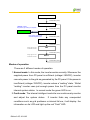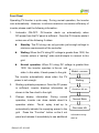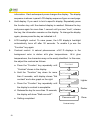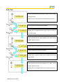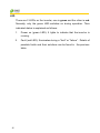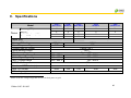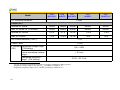
1
CHINT Grid PV-Inverter
CPS SC1.5KTL, CPS SC2KTL, CPS SC2.8KTL, CPS SC4KTL,
CPS SC4KTL-O
Installation and Operation Manual
Version 3.0E 2011.05
Contents
Before you start….................................................................................................... 3
Safety instructions ................................................................................................... 4
Limited Warranty..................................................................................................... 6
1.
Overview......................................................................................................... 7
2.
Features.......................................................................................................... 9
3.
Installation instructions............................................................................... 10
Opening the package............................................................................ 10
Before installation ................................................................................. 10
Mounting PV-Inverter to the wall ........................................................... 12
Connecting to the grid (AC utility) ......................................................... 15
Connect to PV Panel (DC input) ........................................................... 16
Checking .............................................................................................. 17
4.
System Diagram ........................................................................................... 18
5.
Operation of PV-Inverter............................................................................. 19
Initialization for Regulation Setting........................................................ 19
Modes of operation............................................................................... 20
Front Panel arrangement...................................................................... 21
Front Panel........................................................................................... 22
1
LCD Display Sequence......................................................................... 24
Auto Test Setting (Only for ENEL GUIDE 2010 model)........................ 25
Auto Test Record (Only for ENEL GUIDE 2010 model) ....................... 28
Accuracy of the reading ........................................................................ 29
6. Inverter Status.................................................................................................. 30
Display information ............................................................................... 30
LED ...................................................................................................... 35
7. Communications.............................................................................................. 36
8. Trouble shooting.............................................................................................. 38
9. Specifications................................................................................................... 40
Typical Efficiency Charts vs. Load ........................................................ 45
10. Disposal.......................................................................................................... 46
11. Contact Information ....................................................................................... 47
12. Regulation & Certificate ................................................................................ 48
VDE Certificate (European models)...................................................... 49
Edition 3.0E, 2011/05
Before you start…
Congratulations on choosing CHINT Grid PV-Inverter (referred to in this
manual as “PV-Inverter”, or simply “Inverter”). CHINT Grid PV-Inverter is a
highly reliable product due to its innovative design and perfect quality control.
Such an inverter is used in high demand, grid-linked PV systems.
This manual contains important information regarding
installation and safe operation of this unit. Be sure to read this
manual carefully before using.
If you encounter any prob lems during installation or operation of th is
unit, first che ck this manual before contacting your local dealer or
representative. Instructions inside th is manual will help you s olve most
installation and operation difficulties.
Thank you once again that our product is chosen, and wishes you enjoy
CHINT PV-Inverter.
3
Safety instructions
Risk of Electric Shock
1.
Do not remove the casing.
The Inverter contains no user
serviceable parts. Refer servicing to qualified service personnel.
2.
Both AC and DC voltage sources are terminated inside the
PV-Inverter. Please disconnect these circuits before servicing.
3.
When a photovoltaic panel is exposed to light, it generates a DC
voltage. When connected to this equipment, a photovoltaic panel
will charge the DC link capacitors.
4.
Energy stored in this equipment’s DC link capacitors presents a
risk of electric shock. Even after the unit is disconnected from the
grid and photovoltaic panels, high voltages may still exist inside
the PV-Inverter.
Do not remove the casing until at least 30
minutes after disconnecting all power sources.
5.
This unit is designed to feed power to the public power grid (utility)
only. Do not connect this unit to an AC source or generator.
Connecting the Inverter to external devices could result in serious
damage to your equipment.
6.
Carefully remove the unit from its packaging and inspect for
external damage. If you find any imperfections, please contact
your local dealer.
Edition 3.0E, 2011/05
Hot surfaces
Although designed to meet all safety requirements, some parts and
surfaces of the PV-Inverter are still hot during operation. To reduce the
risk of injury, do not touch the heat sink at the back of the Inverter or
nearby surfaces while it is operating.
5
Limited Warranty
The Inverter comes with a standard 5-year warranty. An optional
extended warranty is available for purchase before the unit is delivered to the
end user. T his warranty includes all defects of design, components and
manufacturing. Excluded from warranty are damages due to:
z
Breaking the product seal (opening the casing)
z
Improper transportation and delivery
z
Unqualified persons opening the unit
z
Improper installation
z
Unauthorized modification, testing or repairing
z
Use and application beyond the definition in this manual
z
Application beyond the scope of safety standards (VDE, UL etc.)
z
Acts of nature such as lighting, fire, storm etc.
The right to repair and/or replace the unit is at th e manufacturers’
discretion. Any damages discovered during installation should be submitted
via a written damage report within 5 wo rking days of re ceiving the
PV-Inverter. Manuf acturer are no t responsible for damages beyond the
Scope of this warranty.
Edition 3.0E, 2011/05
1. Overview
Model
CPS SC1.5KTL
CPS SC2KTL
CPS SC2.8KTL
CPS SC4KTL
CPS SC4KTL-O
7
Front View
Bottom View
Parts Description
LCD Display: Showing the
Display information switch
Operation LED,
inverter status
Optional communications
Green, normal
slot: RS485 & others
Operation LED,
Red, fault status
Solar panel input
Edition 3.0E, 2011/05
RS232 cover
Utility (AC) connection:
Terminal Block
2. Features
9
z
Very high conversion efficiency
z
Automatic MPPT (Maximum Power Point Tracking)
z
Higher power capacity than similar products of the same size.
z
Embedded LCD display showing complete status information
z
Natural convection cooling. Quiet, fan-less design
z
Stylish, modern casing
z
Compact, small profile
z
High reliability
z
Easy installation
z
Maintenance free
z
Standard RS-232, optional RS-485 and others
z
Embedded ENS meets VDE 0126-1-1
z
No external GFCI breaker is required
3. Installation instructions
Opening the package
After opening the package, please check the contents of the box. It
should contain the following:
1.
One CHINT inverter
2.
Instruction manual
3.
One mounting frame
4.
4 mounting screws
5.
2 safety-lock screws
6.
One cable gland (PG21) for AC cable in CPS
SC4KTL and
SC4KTL-O
7.
One AC socket assembly in C PS SC1.5KTL,SC2KTL and
SC2.8KTL
Before installation
Before starting installation please consider the following items:
CPS SC1.5KTL~SC4KTL are designed for indoor usage
(IP43). Do not expose the unit to wet, or moist conditions.
Although the CPS SC4KTL-O is designed for outdoor application (IP65),
however we recommend not exposing the PV-Inverter to moist or wet
environments.
For optimal usage do not expose the PV-Inverter to direct
sunlight. Direct sunlight increases the internal temperature
that may reduce conversion efficiency.
Edition 3.0E, 2011/05
9
Check the ambient temperature of ins tallation is within specified
range -20 ~ +55°C.
9
The AC grid voltage is 230VAC, 50Hz.
9
Electric utility company has approved the grid connection.
9
Qualified personnel are performing the installation.
9
Adequate convection space surrounds the inverter.
9
Inverter is being installed away from explosive vapors.
9
No flammable items are near the inverter.
The PV-Inverter can be installed and operated at locations where
the ambient temperature is up to 55°C.
However, for optimal
operation, it is recommended that the PV-Inverter is installed where the
ambient temperature is between 0~40°C.
11
Mounting PV-Inverter to the wall
1.
Select a wall or solid vertical surface that can support the PV-Inverter.
2.
PV-Inverter requires adequate cooling sp ace. Allow at
space above and below the inverter.
3.
Using the mounting frame as a
template, drill 4 holes as illustrated in
the following figures.
4.
Fix the mounting frame as the figure
shows.
Edition 3.0E, 2011/05
least 30cm
5.
Hang PV-Inverter on the mounting frame.
6.
Check
the
installation
conditions.
a) Do not install the PV-Inverter
on a slanted surface.
b) Check the upper straps of
PV-Inverter and ensure it fits
on to the bracket.
13
c) Insert safety-lock screws to the bottom leg to secure the inverter.
Check the secure mounting of the PV-Inverter by trying to raise it
from the bottom. The PV-Inverter should remain firmly attached.
Select the installation location so that the status display can be easily viewed.
Choose a strong mounting wall to prevent vibrations while PV-Inverter is
operating.
Edition 3.0E, 2011/05
Connecting to the grid (AC utility)
1.
Measure grid (utility) voltage and frequency. It should be 230VAC, 50Hz,
and single phase.
2.
Open the breaker or fuse between PV-Inverter and utility.
3.
For CPS SC1. 5KTL, SC2.8KTL, SC2KTL, SC4KTL and SC4KT L-O,
connect AC wires as follows:
z
Insert utility wires through cable gland. Connect wires according t o
polarities indicated on terminal block. L → LINE (brown or black), N
→ Neutral (blue) and → system ground (yellow-green).
z
Fasten the gland plate with attached screws.
z
Twist the gland so that the cable is firmly fixed.
z
Refer to left figure.
15
To prevent risk of electric shock, ensure the ground wire is properly earthed
before operating the PV-Inverter.
4.
Suggested cable width for AC wire
Model
CPS SC1.5KTL /
CPS SC2KTL
CPS SC2.8KTL
CPS SC4KTL /
CPS SC4KTL-O
Diameter φ
(mm)
≥1.29
≥1.63
≥2.05
Area (mm2)
AWG no.
≥1.5
≤16
≥2.0
≥2.5
≤14
≤12
Connect to PV Panel (DC input)
1.
Make sure the maximum open circuit voltage
(Voc) of each PV string is less than 500VDC (or
450VDC for CPS SC1. 5KTL) UNDER ANY
CONDITION. W e recommend use the solar
modules, whose total UMPP at STC in the string
between 250VDC and 350 VDC (200VDC and
320VDC for CPS SC1. 5KTL) with amb ient
temperature 25°C.
2.
Use
Wieland
connectors
for
PV a rray
terminals.
3.
Connect the positive and negat ive terminals from the PV p anel to
positive (+) terminals and negative (-) terminals on the PV-Inverter.
Before connecting PV panels to DC terminals, please make sure
the polarity is correct.
Edition 3.0E, 2011/05
Incorrect polarity connection could
permanently damage the unit.
Check short-circuited current of the PV string. The total short-circuit
current of the PV string should be less than the inverter ’s maximum
DC current.
High voltages exist when the PV panel is exposed to the sun. To
reduce risk of electric shock, avoid touching live components and
treat connection terminals carefully.
Checking
1.
When the PV panels are connected and their output voltage is greater
than 100 VDC but the AC grid is not yet connected, the message on the
LCD display produce the following messages in order: “MODEL= CPS
SCxxKTL-x” -> “Waiting” -> “No Utility”. The display repeats “No Utility”
and the RED “fault LED” turns on.
2.
Close the A C breaker or fuse between PV-Inverter and grid. The
normal operating sequence begins.
3.
Under normal operating conditions the LCD displays “Watt=xxxx.xW”.
That is the power fed to the grid. The green LED turns lights-up.
4.
17
This completes the check.
4. System Diagram
The typical connection diagram for the entire PV system is shown in the
following figure.
1.
PV Panel: Provide DC power to inverter
2.
PV-Inverter: Converts DC (Direct Current) power from PV panel(s) to
AC (Alternating Current) power.
Becaus e the PV-Inverter is
grid-connected it controls the current amplitude according to the PV
Panel power supply. The inverter always tries to convert the maximum
power from your PV panel(s).
3.
Connection system: This “interface” between Utility and PV-Inverter
may consist of electr ical breaker, fuse and connec ting terminals. To
comply with local safety standards and codes, the connection system
should be designed and implemented by a qualified technician.
4.
Utility: Referred to as “grid” in this manual, is the way your ele ctric
power company provides power to your place. Plea se note that t he
PV-Inverter can only connect to low-voltage systems (namely,
230VAC/50Hz).
Edition 3.0E, 2011/05
5. Operation of PV-Inverter
Initialization for Regulation Setting
1.
The Inverter provides a “Initialization” function at the first time
start-up as an process in which user is able to select the intended
regulation type before normal operation.
2.
The inverter will not able to operate normally before regulation
setting is completed even though it is connected correctly at both
DC input and AC output.
3.
The folliwing figure illustrates the process of “Initialization”, and
the display sequence of regulation available.
4.
For example, if user need to set regulation type to RD1663, user
have to power on the inverter to start the “Initialization” and
change the menu by button control until RD1663 present, hold on
to this regulation page and then press the button for 5 more
seconds unitl “INIT OK” message appeared, the regulation
setting is completed.
Note: Incorrect regulation type setting would cause inverter to
non-operation, please consult with your dealer if you are not
familiar with regulation type setting.
19
Initialization
Press button (1sec)
VDE0126-1-1
“INIT OK” indicate
Regulation type setting is completed
Press button (1sec)
INIT OK
RD1663
Press button (5sec) to set
intended Regulation type
Press button (1sec)
ENEL Guide 2010
Press button (1sec)
Only appear on
relevant model
CGC
Press button (1sec)
Only appear on
relevant model
G83/1-1
Press button (1sec)
Modes of operation
There are 3 different modes of operation.
1. Normal mode: In this mode, the inverter works normally. Whenever the
supplied power from PV panel is sufficient (voltage>150VDC), inverter
converts power to the grid as generated by the PV panel. If the power is
insufficient (voltage<120VDC), inverter enters a “waiting” state. Whilst
“waiting” inverter uses just enough power from the PV panel monitor
internal system status. In normal mode the green LED is on.
2. Fault mode: The internal intelligent controller can continuously monitor
and adjust the system status.
If inverter finds any unexpected
conditions such as gr id problems or internal fail ure, it will display the
information on its LCD and light up the red “Fault” LED.
Edition 3.0E, 2011/05
3. Shutdown mode: During per iods of little or no sunlight, inverter
automatically stops running. In this mode, inverter does not take any
power from the gr id. The display and LED’s on the front panel do not
work.
Front Panel arrangement
21
Front Panel
Operating PV-Inverter is quite easy. During normal operation, the inverter
runs automatically. However, to achieve maximum conversion efficiency of
inverter please read the following information:
1.
Automatic ON-OFF: PV-Inverter starts up automatically when
DC-power from the PV panel is sufficient. Once the PV-Inverter starts it
enters one of the following 3 states:
z
Standby: The PV st ring can only provide just enough voltage to
minimum requirements of the controller.
z
Waiting: When the PV string DC voltage is greater than 100V, the
inverter enters a “waiting” state and at tempts to connect to th e
grid.
z
Normal operation: When PV string DC voltage is greater than
150V, the inverter operates in the nor mal
state. In this state, it feeds power to the grid.
Model = xxxxxx
The inverter automatically stops when the PV
power is not enough.
2.
Waiting
Starting-up display sequence: Once the PV power
is sufficient, inverter displays information as
Checking= XX sec
shown in the flow chart to the right.
3.
Change
display
information:
During
normal
operation, inverter can show details about it s
operation status.
The di
splay is set up to
automatically indicate the supplying power to the
grid.
Press the “Function” button on the fr ont
panel and release it immediately to see additional
Edition 3.0E, 2011/05
Normal State
Pac=xxxx.xW
Information during
start-up
information. Each subsequent press changes the display. The display
sequence is shown in panel LCD display sequence figure on next page.
4.
Hold display: If you want to hold a specific display. Repeatedly press
the function key until the desired display is reached. Release the key
and press again for more than 1 second until you see “ Lock”, release
the key; the information remains on the display. To change the display
again, please press the key as indicated in 3
5.
LCD backlight control: To save power, the LCD display’s backlight
automatically turns off after 30 seconds. To enable it, pr ess the
“Function” key again.
6.
Contrast control: A natural phenomenon of LC D displays is the
background color is darker at hi gher temperatures.
At hi gher
temperatures, the characters may not be easily identified. In this case,
the adjust the contrast as follows:
a. Press the “Function” key repeatedly until
Contrast
“Contrast” shows in the display.
b. Hold the “Function” key down for more
Set Contrast
than 2 seconds, until display shows “Set
contrast” and a bar graph on the right.
c. Press the “Function” key repeatedly until
Set Contrast
the display’s contrast is acceptable.
d. Release the key for more than 10 seconds,
Set Contrast
Lighter
Darker
the display will show “Watt=xxxx.xW”.
e. Setting completed
Pac=xxxx.xW
Contrast setup
23
Done
LCD Display Sequence
LCD display sequence
Pac=xxxx.xW
Feeding wattage
Model=xxxxxx
Turn-on backlight
Etoday=xx.xxkWh
Cx.xx
Feeding energy of
Normal State
the current day
Eac=xx.xkWh
Accumulate energy.
Contrast
Vdc =xxx.xV
DC-PV voltage
Set Language
Iac= xx.xA
Feeding current
Vac = xxx.xV
Frequency=xx.xHz
AC Frequency
Model information
F/W version
Operating status
Contrast Adj.
Language setting
Grid voltage
Set 60HzFuction
Set frequency
Auto Test Set
For ENEL GUIDE
2010 only
LCD display sequence
Edition 3.0E, 2011/05
Auto Test Setting (Only for ENEL GUIDE 2010 model)
The Inverter is supplied with an auto test function which enables the user to
check that the protection interface is operating correctly. In order to select
this function, press the function button until the message "AUTO TEST SET"
appears on the display panel. Press and hold the same button for at least 5
seconds to initiate the auto test procedure.
Press function button until Auto test set appears.
Press and hold function button for more than 5s.
Upper voltage threshold will be checked.
Display shows variation between upper voltage threshold
and mains supply.
If the threshold and the grid voltage are equal, the PV
Inverter switches to fault.
Display shows a message similar to this witch-off time OK.
Lower voltage threshold will be checked.
Display shows variation between lower voltage threshold
and mains supply.
25
Auto Test
If the threshold and the grid voltage are equal, the PV Inverter
switches to fault.
Display shows a message similar to this switch-off time OK.
Upper frequency threshold will be checked.
Display shows variation between upper frequency threshold
and mains supply.
If the threshold and the grid frequency are equal, the PV
Inverter switches to fault.
Display shows a message similar to this switch-off time OK.
Lower voltage threshold will be checked.
Display shows variation between lower voltage threshold and
mains supply.
If the threshold and the grid frequency are equal, the PV
Inverter switches to fault.
Display shows a message similar to this - switch-off time OK.
Edition 3.0E, 2011/05
Auto Test
If all the above tests have been performed, the display shows
the message TEST PASSED.
PV Inverter switches to normal operation mode.
If one of the above tests failed, the display shows the message
AUTO TEST FAILED.
PV Inverter switches automatically and permanently to fault
status.
Contact the installer.
27
Auto Test Record (Only for ENEL GUIDE 2010 model)
After the Auto test setting, inverter will record the test result values, as
shown in below.
**Press the button for 5 seconds,
the messages shown on th e
screen will change per second.
Un-press the button, the Aut o
Test Record will be shown on the
screen.
If there's no test record, the
message of "No Test Record" will
be shown on the screen.
Edition 3.0E, 2011/05
Maximum Power Point Tracking (MPPT)
A good PV inverter must be IPV (A)
able to convert the maximum
power from any PV panel. Due
to its advanced design, this
PPV (W)
Maximum power point
2
@ 1000W/m ~ 120W
1000W/m 2
5
125
800W/m2
4
100
600W/m2
3
75
maximum power from your PV 2
50
panel in any condition. When the 1
25
PV-Inverter
can
track
the
displayed power on the LCD
output
does
not
change
0
10
20
30
40
50 UPV (V)
dramatically, the inverter is converting the maximum power from panels.
When the LCD power readin g is significantly chan ges, the inverter is
tracking the power according to the varied sunlight.
When the PV panel’s output is low, the feeding DC-power may
drift slowly as does the AC power. It is because PV-Inverter is
tracking maximum DC-power continuously.
Accuracy of the reading
The reading on the LCD is just for reference. We do not recommend
using the data for checking or testing of th e system. Norm ally, its
accuracy is around ±2%. In all ranges of operation, the accuracy is up
to ±5%.
29
6. Inverter Status
This inverter is designed to be user-friendly; therefore, the status of the Inverter can be easily understood
by reading the information shown on the front panel display. All possible messages are shown in the following
table.
Display information
Operating
conditions
In English
In German
In Italian
Description
Power off
-
-
-
PV inverter is totally shutdown, VPV <70V
Standby
Standby
Standby
Standby
70V< Input voltage <120V
Initialization & waiting
Waiting
Warten
Attendere..
Input voltage range 120~150V during
start-up. After PV voltage is higher than 120V,
inverter is waiting for feeding to grid
Checking xxxS
Netzprüfung xxxS
Verifica… xxxS
When PV voltage> 150V, inverter is checking
feeding conditions
Normal
Normalbetrieb
Stato Normale
Inverter is feeding power. After 10 seconds of
this display, LCD will show wattage.
Normal Working
Status
Check grid
Feeding grid, MPPT
Edition 3.0E, 2011/05
30
Operating
conditions
In English
In German
In Italian
Description
FLASH
FLASH
FLASH
FLASH firmware
Instantaneous Output
power
Pac=xxxx.xW
Pac=xxxx.xW
Pac = xxxx.xW
The real time output power in xxxx W
Accumulated energy
information
Eac = xxxxxxkWh
Eac = xxxxxxkWh
E = xxxxxxkWh
Total energy to has been fed to grid since
inverter was installed
Vac=xxx.xV
Uac=xxx.xV
Vac = xxx.xV
Grid voltage in xxx.x VAC
Freq = xx.xHz
Grid frequency in xx.x Hz
FLASH
Monitoring
Parameters
Grid voltage
Grid frequency
Frequency=xx.xHz Frequenz = xx.xHz
Feeding current
Iac=xx.xA
Iac=xx.xA
Iac = xx.xA
Feeding current amount in xx.x A
PV array voltage
Vdc= xxx.x V
Udc= xxx.x V
Vdc=xxx/xxx/xxxV
Input voltage from PV array, xxx.x VDC
Etoday=xxx.xkWh
The accumulated kWh of that day
Daily Energy
31
Etoday=xxx.xxKWh Etoday=xxx.xxKWh
Operating
conditions
In English
In German
In Italian
Description
Isolation failure
Isolation fault
Isolationsfehler
Err.Isolamento
Earth fault of the PV-panels or failure of surge
voltage protection
GFCI active
Ground I fault
Fehlerstrom
I dispers.Alta
Leakage current on ground conductor is too
high
Grid failure
Grid fault
Netzfehler
Err.Rete
Grid measured data is beyond the
specification (voltage & frequency)
No utility
No Utility
Kein Netz
Non disponibile
Utility is not available
PV over voltage
DC–Überspg.
Vdc alta
Input voltage higher than the maximum input
voltage
Consistent Fault
Konsistenzfehler
Err.interno 01
The readings of 2 microprocessors are not
consistent. It could be caused by CPU and/or
other circuit do not function well.
Over temperature
Übertemperatur
Sovratemperatura
The internal temperature is higher than
normal value
System Fault
Input voltage too high
Inverter Fault
Consistent failure
Temperature too high
Edition 3.0E, 2011/05
32
Operating
conditions
In English
In German
In Italian
Description
Output relay failure
Relay Failure
Relaisfehler
Err.relè
The relay between inverter and grid is not
functional
Output DC injection too
high
DC INJ High
DC INJ zu hoch
Idc uscita alta
Output DC injection too high
EEPROM Failure
EEPROM Fehler
Err.interno 02
EEPROM inside has data access problem
Communication failure
between
microprocessors
SCI Failure
CPU Fehlfunktion
Err.interno 03
The communication between MCU inside is
abnormal
DC bus voltage is too
high
High DC Bus
Udc bus zu hoch
Err.interno 04
The DC BUS inside is higher than expected
DC bus voltage is too
low
Low DC Bus
Udc bus zu klein
Err.interno 05
The DC BUS inside is lower than expected
2.5V reference voltage
inside prolem
Ref 2.5V Fault
Uref fehlfunkt.
Err.interno 06
The 2.5V reference inside are abnormal
DC Sensor Fault
DC Sensor Fehler
Err.interno 07
The DC output sensor is abnormal
GFCI Failure
FI-Fehler
Anomalia GFCI
The GFCI detection circuit is abnormal
EEPROM problem
Output DC sensor
abnormal
GFCI detection
problem
33
Operating
conditions
In English
In German
In Italian
Description
System Information
Model display
LCD contrast
CPS SC1.5KTL /
CPS SC2KTL / …
CPS SC1.5KTL /
CPS SC2KTL / …
CPS SC1.5KTL /
CPS SC2KTL / …
Inverter model name
Contrast
Kontrast
Contrasto
The top menu of LCD contrast setting
Set Contrast
Kontrast
Regola contrasto
Setting the contrast of LCD
Lock
Lock
Bloccato
Hold the present display message
Reconnect xxxS
Kontakt in xxx S
Connessione xxx S
The time for reconnect to grid
Firmware version
Ver xx.xx
Ver xx.xx
Ver xx.xx
F/W version information
Setting Language
Set Language
Sprache
Imposta lingua
Set up of the display language
LCD contrast setting
LCD display lock
Waiting for reconnect
to grid
Edition 3.0E, 2011/05
34
LED
There are 2 LED’s on the inverter, one is green and the other is red.
Normally, only the green LED s witches on during operation. Their
indicated status is explained as follows:
1.
Power on (green LED): It lights to indicate that the invert er is
running.
2.
Fault (red LED): Illuminates during a “fault” or “failure”. Details of
possible faults and their solutions can be found in the previous
table.
35
7. Communications
This inverter is equipped with a po werful communications interface and
options. Use “Pro Control” to monitor the status of your PV-Inverter. Also,
qualified personnel can upgrade the firmware using the RS232 port.
1.
RS232: To use the RS232 port, remove the RS232 cover on the bottom
side of the inverter. It is a DB9 socket. The pin definition is
Pin
1
2
3
4
5
6
7
8
9
Functional Description
N.C.
TxD
RxD
N.C.
Common
N.C.
N.C.
N.C.
N.C.
N.C. means “No Connection”
2.
Optional communications port: This port is a very powerful extension.
The inverter can accept a special card designed for the port only. The
RS485 card is used to work with EZ logger and in multiple monitoring
applications. For information of card details, please refer to the user
manual of each individual card. To get the latest information, please
contact with your local dealer or visit our website.
3.
Firmware upgrade: To keep the firmware up to-date, use the RS232 port
and supplied program to upgrade firmware. To do this, please contact
your local service
Edition 3.0E, 2011/05
To prevent risk of damage it is recommended that only authorized
personnel perform firmware upgrades.
37
8. Trouble shooting
In most situations, the inverter requires very little service. However, if inverter
is not able to work perfectly, please refer to the following instructions before
calling your local dealer.
z
Should any problems arise, the red (Fault) LED on the front panel turns
on and the LCD d isplays the relevant information. Please refer to the
following table for a list of potential problems and their solutions.
Display
System
Fault
Inverter
Failure
Possible actions
1. Check the impedance is between PV (+) & PV
(-) and the PV-Inverter is earthed. The
Isolation fault
impedance must be greater than 2MΩ
2. If the problem persists please call service
1. The ground current is too high.
2. Unplug the inputs from the PV generator and
check the peripheral AC system
Ground I fault
3. After the cause is cleared, re-plug the PV panel
and check PV-Inverter status.
4. If the problem persists please call service.
1. Wait for 30 seconds, if the grid returns to
normal, PV-Inverter automatically restarts.
Grid fault 2. Make sure grid voltage and frequency meet the
specifications
3. If the problem persists please call service
1. Grid is not connected.
No Utility 2. Check grid connection cables.
3. Check grid usability.
1. Check the open PV voltage, see if it is greater
than or too close to 500V (450V for CPS
PV over
SC1.5KTL).
Voltage
2. If PV voltage is less than 500 VDC (450 VDC,) and
the problem still occurs, please call local service
1. Disconnect PV (+) or PV (-) from the input,
Consistent
restart the PV-Inverter
Fault
2. If it does not work, call service
Edition 3.0E, 2011/05
1. The internal temperature is higher than
specified normal value
Over
2. Find a way to reduce the ambient temperature.
temperature
3. Or move the inverter to a cooler environment
4. If it is not effective, call local service
Relay Failure
DC INJ High
EEPROM
1. Disconnect ALL PV (+) or PV (-)
Failure
2. Wait for few seconds
SCI Failure
3. After the LCD switches off, reconnect and
High DC Bus
check again
Low DC Bus 4. If the message reappears call your local
Ref 2.5V Fault
service
DC Sensor
Fault
GFCI Failure
z
If there is no display on the panel, please check PV-input connections.
If the voltage is higher than 150V, call your local service.
z
During periods of little or no sunlight, the PV-Inverter may continuously
start up and shut down. This is due to insufficient power generated to
operate the control circuits.
39
9. Specifications
Model
Market
Germany (DE)
Italy (IT)
United Kingdom (UK)
China (CN)
CPS
SC1.5KTL
CPS
SC2KTL
CPS
SC2.8KTL
CPS
SC4KTL
CPS
SC4KTL-O
V
V
V
-
V
V
V
-
V
V
V
V
V
V
V
-
V
V
-
Input (DC)
Nominal DC voltage
Max. PV open voltage
System start-up voltage
Initial feeding voltage
Shutdown voltage
Working voltage range1
Full rating voltage range
MPPT voltage range
360 V
450V
400 V
500V
Typical 120 V
150 V
Typical 70V
100 ~ 500 V
250 ~ 450 V
150 ~ 450 V
100 ~ 450 V
200 ~ 405 V
150 ~ 405 V
MPPT efficiency
Number of MPP tracker(s)
Max. DC current
DC voltage ripple
1
> 99%
1
8.9A
10A
13A
20A
20A
< 10%
Which is the DC voltage range that inverter can feed power to grid.
Edition 3.0E, 2011/05
40
Model
CPS
SC1.5KTL
CPS
SC2KTL
CPS
SC2.8KTL
DC insulation resistance2
CPS
SC4KTL
CPS
SC4KTL-O
> 5MΩ
Output (AC)
Nominal AC power
1500W
2000W
2800W
4000W
4000W
Max. AC power (in 10 minutes)
1650W
2200W
3000W
4400W
4400W
Nominal AC current
6.6 A
8.7 A
12.2 A
17.4 A
17.4 A
Max. AC current
7.9 A
10.5 A
14.3 A
20 A
20 A
O/P current distortion (THD i)
< 3%
Power Factor
> 0.99
for Germany Operational voltage range3
(DE)
(F/W Setting)
Disconnection time of
excess operational voltage
range
Operational frequency
range4 (F/W Setting)
2
The DC resistance requirement for positive or negative terminal to chassis ground
Regulation voltage range is 184~264.5 VAC according to VDE0126-1-1
4
Regulation frequency range is 47.5~50.2Hz according to VDE0126-1-1.
3
41
190 ~ 256V
≦ 0.2 sec.
47.55 ~ 50.15 Hz
Model
CPS
SC1.5KTL
CPS
SC2KTL
Disconnection time of
excess operational
frequency range
for Italy
(IT)
5
6
CPS
SC4KTL
CPS
SC4KTL-O
≦0.2 sec.
Re-connecting time after
disconnection
Operational voltage range5
(F/W Setting)
Disconnection time of
excess operational voltage
range
Operational frequency
6
range (F/W Setting)
Disconnection time of
excess operational
frequency range
Re-connecting time after
disconnection
CPS
SC2.8KTL
30 sec
190~267V
Min Voltage protection 0.2 s; Max voltage protection 0.1s
49.75 ~ 50.25 Hz
≦0.1 sec.
60 sec
Regulation voltage range is 184~267 VAC according to ENEL Guide 2010
Regulation frequency range is 49.7~50.3Hz according to ENEL Guide 2010.
Edition 3.0E, 2011/05
42
Model
for United
Kingdom
(UK)
CPS
SC1.5KTL
CPS
SC4KTL
CPS
SC4KTL-O
212~256V
Step1 : 207~246V
Step2 : 189~256V
-
≦1.5 sec.
U/V st1 200.1V(87%), 2.5s
O/V st1 253V(110%),
1s
U/V st2 184V(80%),
0.5s
O/V st2 264.5V(115%), 0.5s
47.05~50.45Hz
St1 47.55~51.45Hz
St2 47.05~51.95Hz
Operational voltage range7
(F/W Setting)
Disconnection time of
excess operational voltage
range
Operational frequency
range8 (F/W Setting)
Disconnection time of
excess operational
frequency range
CPS
SC2KTL
≦0.5 sec.
7 Regulation voltage range is 207~264 VAC according to G83/1-1
Regulation voltage range is 184V-264.5VAC according to G59 Issue 2
8 Regulation frequency range is 47~50.5Hz according to G83/1-1.
Regulation frequency range is 47~52Hz according to G59 Issue 2
43
CPS
SC2.8KTL
U/F st1
O/F st1
U/F st2
O/F st2
47.5Hz,
51.5Hz,
47Hz,
52Hz,
20s
90s
0.5s
0.5s
-
-
-
Model
CPS
SC1.5KTL
Re-connecting time after
disconnection
CPS
SC2KTL
CPS
SC2.8KTL
180 sec
CPS
SC4KTL
CPS
SC4KTL-O
180 sec
-
Efficiency
Max. conversion efficiency
95%
96%
96%
96%
96%
European efficiency
94%
95%
95%
95%
95%
Edition 3.0E, 2011/05
44
Typical Efficiency Charts vs. Load
CPS SC1.5KTL
CPS SC2.8KTL
CPS SC4KTL / CPS SC4KTL-O
specifications may cause actual results to differ.
45
Note: Test equipment tolerances, environmental conditions and model
CPS SC2KTL
10. Disposal
The dealer or installers should re move the PV Inverter from th e array
and contact the supplier for disposal instructions
The inverter must not be disposed of with the household
waste.
Dispose of the PV Inverter at the end of its service life should be done in
accordance with the disposal regulations for el ectronic waste which
apply at the installation site at that time.
Please contact supplier for disposal instruction, the contact information
could be found in Chapter 11. Contact Information.
Edition 3.0E, 2011/05
46
11. Contact Information
Should you ha ve technical problems concerning this product, please
contact our Service line.
We require the fo llowing information in order to pr ovide you with the
necessary assistance:
• Inverter type
• Serial number of the PV Inverter
• Type and number of PV panel connected
• Fault message
• Communication method
SHANGHAI CHINT POWER SYSTEMS CO., LTD.
Add: Building 4, No.855 W enhe Road, Songjiang Dist rict, Shanghai,
201614, China
Tel :+86 - 21 - 3779 1222
Fax:+86 - 21 - 3779 1222 - 6016
Service Hotline:+86 - 21 - 3779 1222 - 6300
CHINT EUROPE (UK) LTD
Unit 5, Bracken Trade Park
Dumers Lane
Bury, BL9 9QP
United Kingdom
Tel: 0044 (0)161 762 9333
Fax: 0044(0)161 762 9898
E-mail: [email protected]
Web: www.chint.co.uk
47
12. Regulation & Certificate
Regulatory Type
VDE0126-1-1
ENEL Guide
Grid
Monitoring 2010
G83/1-1;
G59 Issue 2
Safety
EMC:
EMS / EMI
CE
Edition 3.0E, 2011/05
CPS
CPS
SC1.5KTL SC2KTL
CPS
CPS
SC2.8KTL SC4KTL
CPS
SC4KTL-O
V
VV
V
V
V
VV
V
V
G59 issue2
-
G83/1-1
G83/1-1
G83/1-1
DIN EN 50178 (4.98) (VDE0160) (IEC62103)
EN 61000-6-2
EN 61000-6-3
LVD: 2006/95/EC EMC: 2004/108/EC
48
VDE Certificate (European models)
49