1
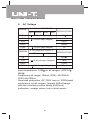
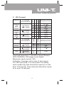
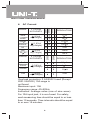
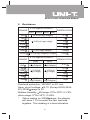
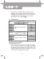
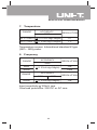
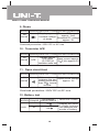
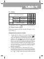
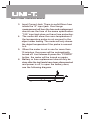
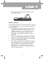
Model UT2000: OPERATING MANUAL
Table of Contents
Title
Introduction
Attention
International Electrical Symbols
Features
Environmental Conditions
Technical Specification
1. Dc Voltage
2. Ac Voltage
3. Dc Current
4. AC Current
5. Resistance
6. Capacitance
7. Temperature
8. Frequency
9. Diode
10 . Transistor hFE
11. Open circuit test
12. Battery test
13. Alarm
14. Square wave output
Page
2
2
2
3
4
5
5
6
7
8
9
10
11
11
12
12
12
12
13
13
Operating Instruction
13
Safety Rules
15
Maintenance
18
1
Model UT2000: OPERATING MANUAL
INTRODUCTION£º
UT2000 series are the large LCD DMM with
accurate reading, stable quality, multifunctional
and modern design of 3 1/2 and 4 1/2 handheld
digital multimeter used for measuring DC voltage
and current, AC voltage and current, resistance,
capacitance, frequency, temperature, positive diode
resistance, transistor hFE and short circuit testing.
It is suitable for engineering design, laboratory
testing and industrial manufacturing and repair etc.
ATTENTION
Please go through the instruction manual before
using your meter and also pay attention to the
section VI. SAFETY RULES.
International Electrical Symbols:
AC (Alternating Current)
DC (Direct Current)
AC or DC
Grounding
Double Insulated
Deficiency of Built-In Battery.
Continuity Test.
Diode.
Fuse.
Warning. Refer to the Operating Manual.
Conforms to Standards of European Union.
2
Model UT2000: OPERATING MANUAL
FEATURES
l
l
l
l
l
l
l
l
l
l
DC basic accuracy: (31/2) 0.5%; (4 1/2) 0.05%.
Max. display:1999 (3 1/2 digit) ; 19999
(4 1/2 digit).
Reading display frequency: 2-3 times per
second.
Automatic indication of polarity, decimal place
and signs. Automatic indication of "1" for
over-range."
" shows when the battery is
insufficient.
Auto-zeroing for capacitance test.
Automatic circuitry protection and buzzer
sounds for over-range and mis-operation.
With automatic power-off function.
Release the lock by press the cases top button.
Adopt large LCD display, 25mm height digit,
the angle of the display can be rotated within
70' to select the most suitable reading angle..
Size: 185x89x32mm.
Weigh: approx. 300g (including battery).
3
Model UT2000: OPERATING MANUAL
ENVIRONMENTAL CONDITIONS
o
o
Guarantee accuracy: 23 C 5 C ; relative humidity:
<75%.
Temperature range: working temperature: 0 C to
40 C (32 F to 104 F),
storing temperature: -10 C to 50 C (14 F to 122 F)
Battery: 9Vbattery (NEDA1604,6F22 or similar type).
Relative humidity: 0 C-31 C,<80%; 31 C-40 C,<50%
Altitude: (operating) 2000 meters, and 10000 meters
for storage.
Replacement Fuse: 5x20mm, 0.2A/250V FAST
(Except Model 2001, 2A/250V FAST)
o
o
o
o
o
o
o
4
o
o
o
o
o
Model UT2000: OPERATING MANUAL
TECHNICAL SPECIFICATION
Accuracy: (a% reading + No. of digits), guaranteed
for 1 year.
1. DC Voltage
RANGE
3 1/2 Digit ACCURACY
2001 2002/5 2006 2007
200mV
2V
100 V
(0.5%of rdg+1digit)
20V
RANGE
100mV
(0.8%of rdg+2digits)
2004
200mV
20V
RESOLUTION
10 V
(0.05%of
(0.1%of
rdg+3digits) rdg+2digits)
200V
1000V
1V
4 1/2Digit ACCURACY
2003
2V
1mV
10mV
200V
1000V
RESOLUTION
100 V
1mV
10mV
(0.1%of
(0.2%of
rdg+5digits) rdg+5digits)
100mV
Input impedance: 10M on all ranges.
Overload protection: DC or AC peck value of
1000V. (expect 200mV range with the maximum
value being 250V rms)
5
Model UT2000: OPERATING MANUAL
2.
AC Voltage
RANGE
3 1/2 Digit ACCURACY
2001 2002/5 2006 2007
200mV
2V
(1.2%of rdg+3digits)
(0.8%of rdg+3digits)
20V
RANGE
1V
4 1/2 Digit ACCURACY
2004
RESOLUTION
100 V
2V
(0.8%of rdg+10digits)
200V
750V
1mV
100mV
(1.2%of rdg+3digits)
2003
20V
100 V
10mV
200V
750V
RESOLUTION
1mV
10mV
(1%of rdg+15digits)
100mV
Input impedance: 10M on all ranges. (2003/4
2M )
Frequency all range: Below 200V; 40-400Hz;
750V;40-200Hz.
Overload protection: AC 750V rms or 1000Vpeak
continuous on all ranges. (expect 200mVrange
with the maximum value being 250Vrms)
Indication: verage value (rms of sine wave).
6
Model UT2000: OPERATING MANUAL
RANGE
3 1/2 Digit
ACCURACY
2001
2002/5
2006
2007
3. DC Current
200 A
2mA
0.1 A
(0.8%of
rdg+1digit)
1 A
20mA
10A
20 A
RANGE
2mA
20mA
(1.2%of
rdg+1digit)
100 A
(2%of
rdg+5digits)
10mA
1mA
10n A
4 1/2 Digit
ACCURACY
2004
2A
10 A
2003
200mA
RESOLUTION
RESOLUTION
0.1 A
(0.5%of
rdg+2digit)
1 A
200mA
(0.75%of
rdg+5digit)
10 A
10A
(2%of
rdg+10digits)
1mA
Overload protection: 0.2A/250V fused (Except
2001:2A/250V) 10A range is not fused.
Maximum input current :10A
Indication: Average value (rms of sine wave)
For 10A input jack, it is non-fused. For safety,
each measuring time should be equal to or less
than 10 seconds. Time intervals should be equal
to or over 15 minutes.
7
Model UT2000: OPERATING MANUAL
AC Current
2001
2002/5
2006
2007
4.
RANGE
3 1/2 Digit
ACCURACY
2mA
(1%of
rdg+3digits)
10 A
(1.8%of
rdg+3digits)
100 A
20mA
1 A
200 A
200mA
RESOLUTION
0.1 A
2A
1mA
10A
10mA
10n A
4 1/2 Digit
ACCURACY
(0.8%of
rdg+10digit)
1 A
200mA
10A
RESOLUTION
0.1 A
2mA
20mA
2004
RANGE
(3%of
rdg+7digits)
2003
20 A
10 A
(2%of
rdg+10digits)
1mA
Overload protection: 0.2A/250V fused (Except
2001:2A/250V) 10A range is
not fused.
Maximum input: 10A
Frequency range: 40-400Hz.
Indication: Average value (rms of sine wave)
For 10A input jack, it is non-fused. For safety,
each measuring time should be equal to or less
than 10 seconds. Time intervals should be equal
to or over 15 minutes.
8
Model UT2000: OPERATING MANUAL
5. Resistance
3 1/2 Digit ACCURACY
RANGE
2001 2002/5 2006 2007
RESOLUTION
(0.8%of rdg+3digits)
0.1
2K
1
20K
(0.8%of rdg+1digit)
10
200
100
200K
1K
2M
20M
200M
10K
(1%of rdg+2digits)
[5%(of rdg-10digits)+10digits]
100K
4 1/2 Digit ACCURACY
RANGE
200
2003
2004
(0.2%of
rdg+5digits)
(0.5%of
rdg+5digits)
(0.2%of
rdg+1digit)
(0.5%of
rdg+1digit)
(0.5%of
rdg+5digits)
(1%of
rdg+5digits)
RESOLUTION
0.01
0.1
2K
20k
1
10
200K
2M
20M
100
1k
Overload protection: 250VDC or AC rms.
Open circuit voltage: 0.7V (Except 2003,2004:
3V) 200M range is 3V.
o
o
Relative Humidity: 2M range: 0 Cto 35 C: 0~75%,
o
o
other range: 0 Cto 35 C: 0~90%.
* When testing on 200M range, the display
will show 1.0 if connect the two test lead
together. This reading is a fixed deviation
9
Model UT2000: OPERATING MANUAL
which does not affect the accuracy of the
reading. If the resistor under measurement is
100M , The reading will be 101.0, the actual
value should be the display value minus
1.0: 101.0 - 1.0 = 100.0 M
6. Capacitance
RANGE
3 1/2 Digit ACCURACY
RESOLUTION
2002/5
2006
2007
2nF
1pF
20nF
10pF
200nF
(2.5%of rdg+3digits)
100pF
2 F
1nF
20 F
10nF
RANGE
4 1/2Digit ACCURACY
2003
2004
RESOLUTION
20nF
1pF
200nF
10pF
(2.5%of rdg+10digits)
2 F
100pF
20 F
1nF
Testing frequency: 400Hz
Testing voltage: 40mV
* When using the capacitance range for testing,
don’t connect a resistor or a charged capacitor
(especially large capacitor) to the meter. The
reading need some times to stabilize or return
to zero when changing the range.
10
Model UT2000: OPERATING MANUAL
7. Temperature
ACCURACY
RANGE
RESOLUTION
2007
o
o
o
o
-40 C~+400 C
400 C~1000 C
o
(0.75%of rdg+3digits)
1C
(1.5%of rdg+15digits)
1C
o
Temperature sensor: International standard K type
(NiCr - NiSi) probe.
8. Frequency
RANGE
ACCURACY
2006
2kHz
20kHz
RANGE
(1.5%of rdg+5digits)
1Hz
10Hz
ACCURACY
2003
20kHz
RESOLUTION
2004
(1.5%of rdg+5digits)
RESOLUTION
1Hz
Input sensitivity: 100mV rms.
Overload protection: 250 DC or AC rms.
11
Model UT2000: OPERATING MANUAL
9. Diode
MODEL RANGE DESCRIPTIONS TESTING CONDITION
Display approx. Forward DC current
approx. 1mA
forward voltage
Reversed DC voltage
of diode
approx. 3V
All
series
Overload protection: 250V DC or AC rms.
10 . Transistor hFE
MODEL RANGE DESCRIPTIONS TESTING CONDITION
All
series
hFE
Display approx.
Base current approx.
hFE value
10 A,Vce approx.3V.
(0~1000) of
transistor under test
11. Open circuit test
MODEL RANGE DESCRIPTIONS TESTING CONDITION
If the resistance Open circuit voltage
between the two
approx. 3V
testing point less
than 30 , buzzer
sounds.
All
series
Overload protection: 250V DC or AC rms.
12. Battery test
INTERNAL
MODEL RANGE RESISTANCE
1.5V
30
2001
9V
1.8k
12
DESCRIPTIONS
Display the value
of voltage between
the cathode and
anode of battery.
Model UT2000: OPERATING MANUAL
ALARM SOUNDS
2001
2002/5
2006
2007
2003
2004
13. Alarm
Switch positionTest leads position
MisV, ,Hz, ,
A or 10A
BATT
operation
10A
A,mA,2A
A
10A
Over
Display >19999*
range
The testing value for
range is meaningless.
14. Square wave output
Frequency approx. 50Hz, range Vp-p 2V (only
for UT2001).
OPERATING INSTRUCTIONS
1. Check the 9V battery by press down the ON
- OFF SWITCH. If the battery is weak,”
“
sign will appear on left bottom side of the
display. The sign next to the test lest lead
jacks is for warning that the input voltage or
current should not exceed the indicated values.
This is used to prevent the damage to the
internal circuitry. The function switch should
be set to the range which you want to test
before operation.
2. Except capacitance, transistor hFE and
temperature which use the special test jack,
the input terminal for all other range should
be “V/ ”, “COM” being the input earth terminal.
13
Model UT2000: OPERATING MANUAL
3. Input Current Jack: There is a 5x20mm fuse
inside the “A” input jack. Over range
measurement will burn the fuse and replacement
should use the fuse of the same specification.
“10A” input jack does not have fuse protection.
4. The meter will show the room temperature if
the temperature probe is not connect to the
object under testing. The meter will only shows
the object temperature if the probe is connect
to it.
5. When the meter is not in use for more than
15 minutes, the power will be automatically
turned off. Just release & press the “POWER”
button, the meter will be turned on again.
6. Battery or fuse replacement should only be
done after the test leads have been disconnected
and power is off, to open the battery door,
see the following diagram.
14
Model UT2000: OPERATING MANUAL
7.
The choice of LCD display angle: see the
following diagram.
SAFETY RULES
The Digit Multimeter is a precise electronic device.
Do not tamper with the circuit and pay attention
to the following:
1. The Meter complies with IEC1010-1 pollution
Degree2 CAT I 1000V, CAT II 600V over
voltage standards. Use the Meter only as
specified in this manual, otherwise the
protection provided by the Meter may be
impaired.
2. CAT I- For signal level, telecommunication,
electronic with small transient over voltage.
3. CAT II- For local level, appliances, main wall
outlets, portable equipment.
4. The meter is designed to withstand the stated
Max. Voltages. If it’s not possible to exclude
without doubts that impulses, transients,
disturbance or for other reasons, these
voltages are exceeded a suitable prescale
(10:1) must be used.
15
Model UT2000: OPERATING MANUAL
5.
6.
7.
8.
9.
10.
11.
12.
13.
14.
15.
Do not operate the Meter before the cabinet
has been closed and screwed safely as
terminal can carry voltage.
Make sure before each measurement the
Meter is set to the suitable range.
Before using the Meter, please inspect the
cabinet and test leads for damaged insulation
or exposed metal.
Connect the red and black test lead to the
correct measuring input jack properly.
Do not input values over the maximum range
of each measurement to avoid damages of
the Meter.
Do not turn the rotary function switch during
Voltage or Current measurement, otherwise
the Meter could be damaged.
Make sure to use new fuses with proper rating
to replace the bad fuses.
To avoid electric shock or damages, do not
apply more than 1000V between the “COM”
terminal and “
” earth ground.
Use caution when working with Voltages
above 60V (DC) or 30Vrms (AC). These
Voltages pose shock hazard.
Replace the battery as soon as the battery
indicator “
” appears. With a low battery,
the Meter might produce false reading that
can lead to electric shock and personal injury.
Turn off the Meter once finished measuring.
Fetch out the battery when the meter will not
be used for long period.
16
Model UT2000: OPERATING MANUAL
16. Do not operate the Meter under adverse
environmental condition including high
temperature and especially humid area as
the Meter’s function may be ineffective after
moisturizing.
17. To avoid damages and dangerous, do not
change the circuit on your own.
18. Periodically wipe the cabinet with a damp
cloth and mid detergent. Do not use abrasives
or solvents.
19. Dispose the used battery proper.
20. The Meter is suitable for indoor use only.
17
Model UT2000: OPERATING MANUAL
Maintenance(1)
This section provides basic maintenance information
including battery and fuse replacement instruction.
Warning
Do not attempt to repair or service your Meter unless
you are qualified to do so and have the relevant
calibration, performance test, and service information.
To avoid electrical shock or damage to the Meter, do
not get water inside the case.
1.General Service
l Periodically wipe the case with a damp cloth and mild
detergent. Do not use abrasives or solvents.
l To clean the terminals with cotton bar with detergent,
as dirt or moisture in the terminals can affect readings.
l Turn the Meter power off when it is not in use and
take out the battery when not using for a long time.
l Do not store the Meter in a place of humidity, high
temperature, explosive, inflammable and strong
magnetic field.
2.Replacing the Battery
Warning
To avoid false readings, which could lead to possible
electric shock or personal injury, replace the battery
as soon as the battery indicator “
”appears.
To replace the battery:
1.
2.
3.
Disconnect the connection between the testing leads
and the circuit under test, and remove the testing
leads away from the input terminals of the Meter.
Turn the Meter power off.
Remove the screw from the battery and fuse
compartment, and separate the battery and fuse
compartment from the case bottom.
18
Model UT2000: OPERATING MANUAL
Maintenance(2)
4. Remove the battery from the battery compartment.
5. Replace the battery with a new 9V battery (NEDA
1604 or 6F22 or 006P).
6. Rejoin the case bottom and battery and fuse
compartment, and reinstall the screw.
3.Replacing the Fuses
Warning
To avoid electrical shock or arc blast, or personal
injury or damage to the Meter, use specified fuses
ONLY in accordance with the following procedure.
To replace the Meter’s fuse:
1.
2.
3.
4.
5.
6.
Disconnect the connection between the testing leads
and the circuit under test, and remove the testing
leads away from the input terminals of the Meter.
Turn the Meter power off.
Remove the screw from the battery and fuse
compartment, and separate the battery and fuse
compartment from the case bottom.
Remove the fuse by gently prying one end loose,
and then take out the fuse from its bracket.
Install ONLY replacement fuses with the identical
type and specification as follows and make sure the
fuse is fixed firmly in the bracket.
Model UT2002, UT2003, UT2004, UT2005, UT2006
and UT2007: 0.2A, 250V, fast type, 5x20mm.
Model UT2001: 2A, 250V, fast type, 5x20mm.
Rejoin the case bottom and battery and fuse
compartment, and reinstall the screw.
Replacement of the fuses is seldom required. Burning
of a fuse always results from improper operation.
~ END ~
This operating manual is subject to change without notice.
19
Model UT2000: OPERATING MANUAL
Copyright 2001 Uni-Trend International Limited.
All rights reserved.
Manufacturer: UNI-TREND TECHNOLOGY(DONG GUAN)LIMITED
Address: Dong Fang Da Dao, Bei Shan Dong Fang Industrial
Development District, Hu Men Town, Dong Guan City,
Guang Dong Province, China
Headquarters: Uni-Trend International Limited
Address: Rm901, 9/F, Nanyang Plaza 57 Hung To Road
Kwun Tong Kowloon, Hong Kong
Tel: (852) 2950 9168
Fax: (852) 2950 9303
Email: [email protected]
http://www.uni-trend.com
20