1
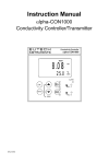
Instruction Manual
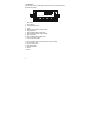
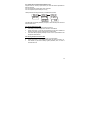
αlpha TDS 200
1/8 DIN Total Dissolved Solids Controller with
Temperature display and Transmitter
Technolo gy Made Easy ...
68X276105 rev 0
08/2002
PREFACE
This manual serves to explain the use of the αlpha TDS 200
controller/transmitter. This manual functions in two ways: first, as a step-bystep guide to help you operate the meter; second, it serves as a handy
reference guide.
This manual is written to cover as many anticipated applications of the αlpha
TDS 200 controller/transmitter as possible. If there are doubts in the use of the
αlpha TDS 200 controller/transmitter, do not hesitate to contact the nearest
Eutech Instruments Authorized Distributor.
Eutech Instruments cannot accept any responsibility for damage or malfunction
to the controller/transmitter caused by improper use of the instrument.
Remember to fill in the guarantee card and mail it to your Authorized Distributor
or Eutech Instruments Pte Ltd.
The information presented in this manual is subjected to change without notice
as improvements are made, and does not represent a commitment on the part
of Eutech Instruments Pte Ltd.
Copyright© Aug 2002 Eutech Instruments Pte Ltd. All rights reserved.
TABLE OF CONTENTS
1
INTRODUCTION
5
2
SAFETY INFORMATION
6
3
OVERVIEW
7
3.1
FRONT PANEL
7
3.2
BACK PANEL
8
3.3
WIRING
3.4
PANEL-MOUNTING THE CONTROLLER
9
10
4
MEASUREMENT MODE
11
5
PASSWORD
12
6
TDS CALIBRATION
14
7
TEMPERATURE CALIBRATION
17
8
SETUP MODE
18
8.1
GENERAL INFORMATION
18
8.2
SETUP MODE OVERVIEW
19
8.3
SET POINT 1 – P1.0
21
8.4
SET POINT 2 – P2.0
24
8.5
MEASUREMENT RANGE SELECTION – P3.0
26
8.6
CONFIGURE TEMPERATURE SETTINGS – P4.0
27
8.7
VIEWING TDS CALIBRATION DATA – P5.0
28
8.8
VIEWING TDS / TEMPERATURE ELECTRODE DATA – P6.0
29
8.9
SET TDS FACTOR – P7.0
30
8.10 CONTROLLER RESET – P8.0
9
RELAYS
30
32
10 TRANSMITTER FUNCTION
32
11 SPECIFICATIONS
33
12 ACCESSORIES
34
13 GENERAL INFORMATION
37
1 INTRODUCTION
Thank you for purchasing a ⅛ DIN TDS 200 Controller. This controller is part of a series
of quality process controllers available from Eutech Instruments. These sturdy,
economical TDS controllers are designed with the features and reliability of a much more
expensive instrument.
Your controller includes:
•
•
Removable terminal blocks for easy connections;
Two mounting brackets for easy panel mounting;
Some features of this controller are:
• Two set point, two SPDT relay operation
• Scrolling, 14-segment LED guides user easily through setup functions
• Reliable power supply from 85 to 260 V AC, 50/60 Hz or DC withstands voltage
fluctuations
• Push-button operation from the front panel
• Single-point calibration for each individual range
• Adjustable hysteresis band prevents rapid contact switching around set-point
• Selectable automatic or manual temperature compensation
• Two-level password protection
• Removable terminal strips for quick and easy connections
• Built-in memory backup retains setup even if power fails, and lets you configure
unit before installation
• Isolated 4-20 mA output for remote monitoring or hard copy recording
5
2 SAFETY INFORMATION
The Eutech Controller/Transmitter shall be installed and operated only in the manner
specified in the Instruction manual. Only skilled, trained or authorized person should
carry out installation, setup and operation of the instrument.
Before powering up the unit, make sure that power source it is connected to, is as
specified in the top label. Failure to do so may result in a permanent damage to the unit.
The unit has live and exposed parts inside. If it has to be opened, make sure that the
power to the unit is off and disconnected.
The unit is Fuse protected. In the event the fuse has to be replaced, use only those as
specified in the manual.
The degree of protection against electric shock will be achieved only by
observance of the corresponding installation rules.
6
3 OVERVIEW
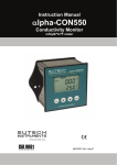
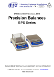
3.1 Front Panel
The front panel consists of a 4-digit LED display, 8 LED annunciators and 4 keys.
Annunciators
1. REL 1
2. REL 2
3. MEAS
4. CAL
5. SETUP
6. ppm
7. oC
8. ppt
Displayed when Relay 1 is activated
Displayed when Relay 2 is activated
Displayed in measurement mode
Displayed in calibration mode
Displayed in setup mode
Displayed when measurement range in parts-per-million
Unit of the displayed parameter (temperature)
Displayed when measurement range in parts-per-thousands
Keys
9. MODE
10. ENTER
11. ▲(increment)
11. ▼(decrement)
12. LED Display
Toggle between TDS and temperature display
Confirm changes or to enter into further levels of sub-menu
Use during calibration and setup modes to increment values.
Press ▲/▼keys together to escape to Measurement mode
Use during calibration and setup modes to decrease values.
Press ▲/▼keys together to escape to Measurement mode
14 segment LED display
8.8.8.8.
7
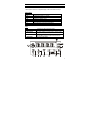
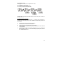
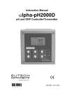
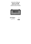
3.2 Back Panel
The back panel consists of three different connectors that can be used with removable
terminal blocks (included):
19 18 17 16 15 14 13
12 11 10 9 8 7 6 5 4
3 2 1
1. VAC live wire
2. VAC neutral wire
3. VAC protective ground wire
4. unused
5. Relay 2 deactivated position (normally closed)
6. Relay 2 center pole
7. Relay 2 activated position (normally open)
8. Relay 1 deactivated position (normally closed)
9. Relay 1 center pole
10. Relay 1 activated position (normally open)
11. 4-20 mA connection, negative
12. 4-20 mA connection, positive
13. Pt 100 connection: sense (jumper to terminal 14 if using 2-wire RTD)
14. Pt 100 connection: input
15. Pt 100 connection: ground
16. TDS positive terminal
17. TDS negative terminal
18. unused
19. unused
8
3.3 Wiring
Caution: Ensure electrical mains is disconnected before proceeding.
1. Connect the power supply to the three-pin terminal block
• VAC live wire = 1
• VAC neutral wire = 2
• VAC protective ground wire = 3
αlpha TDS 200 controller accepts voltages from 85 to 260 VAC, 50/60 Hz or DC.
2. Connect the Pt 100 leads to terminals 13 to 15 of the seven-pin terminal block. Either
wire can be connected to either terminal. Terminals 13 and 14 must be shunted
unless using a 3-wire RTD.
NOTE: TDS 200 is factory set for Automatic temperature compensation. MTC can be
selected in Program P4.0.
3. Power on the controller. The display automatically shows the TDS reading, the ppm
and ‘MEAS’ annunciators lights.
NOTE: In the event Pt 100 is not connected or the connection is broken in the ATC
mode, the display flashes in TDS mode and display OR in temperature mode.
9
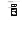
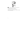
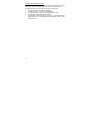
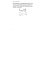
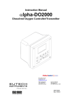
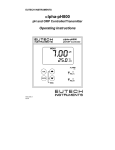
3.4 Panel-mounting the controller
The supplied mounting hardware allows surface mounting to all panels and protective
enclosures. Mounting cut-out size is 91 x 45 mm.
To attach the mounting to the controller:
2.
Screw the threaded-rod through the catch in a clock-wise direction. Tighten until the
catch holds the controller firmly against the back of the panel or protective housing.
Repeat on the other side.
Catch
Threaded rod
approx. 100
Catch
Threaded
Align the catch to the side of the controller, and insert threaded rods through catch.
Wall pa
1.
approx. 154.20
TOP VIEW
SIDE VIEW
10
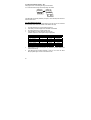
4 MEASUREMENT MODE
Press MODE to toggle between:
• TDS measurement mode and
• Temperature measurement mode
Total Dissolved Solids Measurement Mode
The controller displays the selected TDS range number, R X (X ranges from 1 to 8), for 2
seconds before displaying the TDS measurement.
TDS Range
0.00 – 10.00 ppm
0.0 – 100.0 ppm
0.0 – 100.0 ppm
0 – 1000 ppm
0.00 – 5.00 ppt
0.00 – 10.00 ppt
0.0 – 100.0 ppt
0.0 – 100.0 ppt
Range No., R
1
2
3
4
5
6
7
8
Resolution
0.01 ppm
0.1 ppm
0.1 ppm
1 ppm
0.01 ppt
0.01 ppt
0.1 ppt
0.1 ppt
Cell Constant
0.1
0.1
1
1
1
1
1
10
Temperature Measurement mode
Press MODE key once to view the temperature measurement. The display shows ATC
(Automatic Temperature Compensation) or MTC (Manual Temperature Compensation),
then the current measured temperature (for ATC) or the set temperature (for MTC). The
oC annunciator lights when you are measuring temperature.
NOTE: After pressing the MODE key to display Temperature, if there is no further keypress, the Controller will automatically revert to TDS Measurement mode after about 30
seconds.
See Setup program P4.0 for further instructions.
11
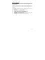
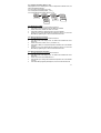
5 PASSWORD
To access Calibration and Setup functions, you need to enter a password code. You
cannot change calibration and setup parameters unless you first enter the password.
The αlpha TDS 200 controller features two separate passwords:
• TDS and Temperature calibration mode password = 011
• Setup program password = 022
To enter the password:
1.
Press ENTER twice. The display reads “P.000”. The first “0” flashes.
2.
Press ENTER again to leave the first digit “0” and to scroll to the next number.
3.
Press the ▲or ▼keys to change the second digit to the correct number (1 or 2).
Press ENTER.
4.
Press the ▲or ▼keys to change the second digit to the correct number (1 or 2).
Press ENTER.
If you enter an incorrect digit, press MODE to back up.
5.
Press ENTER again. You are now in Calibration mode or Setup mode, depending
on password entered.
Note: In the Password Entry mode, if there is no key-press for more than 30 seconds,
Controller will automatically revert to measurement mode.
12
P.
P.000
P.000
P.010
P.020
P.011
P.022
13
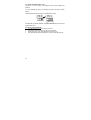
6 TDS CALIBRATION
IMPORTANT: When Calibration mode is entered, controller automatically goes into a
“HOLD” mode where the 4-20 mA output freezes and relays are de-activated (if it was in
an activated condition). Upon return to measurement mode, both 4-20mA output and
relay activities resume, depending on settings.
The αlpha TDS 200 controller includes 8 total dissolved solids measurement ranges.
One-point slope calibration is possible, in each range.
Choose fresh standard solutions, whose value is reasonably close to the measurement
value.
Before calibration, make sure electrode is clean. Use iso-propyl alcohol followed by
thorough rinsing in distilled water to clean electrode.
Important: To achieve a successful TDS calibration, two conditions must be satisfied:
1.
Difference between measured value of standard solution, and actual value of
standard
solution,
must
be
within
±
40
%.
(e.g. if value of standard solution is 500 ppm, then allowable measured
values by controller must be within 700 ppm {+ 40%} and 300 ppm{- 40%});
and
2.
the lowest possible value must be at least 10% of full scale
(e.g. if range of 0 to 1000 ppm is selected, min. measured value at
calibration, must be at least 100.0 ppm).
14
If any or both conditions are not satisfied, controller will display ERR 1 (blinking).
1.
2.
3.
Key in the password “011” using the method described in Section 5.
Controller flashes the value of the standard solution.
Use electrode to agitate standard solution to obtain a homogeneous solution and
to dislodge any bubbles. Allow electrode time to stabilize with solution temperature.
4.
Use ▲/ ▼keys to adjust displayed readings to the value of the standard solution.
Press ENTER.
5.
If any of the two conditions mentioned above is not satisfied, controller will display
ERR1, blinking.
6.
If calibration is successful, Controller displays DONE, blinking. Press ENTER to
revert to TDS measurement mode (Relays and 4-20 mA output resume activities
as per previous settings).
NOTE: To clear the ERR1 display and return to calibration mode, press ▲/ ▼ keys
together.
15
509
500
ENTER
done
ENTER
Notes:
You can view the calibrated TDS value from Setup program. See Setup program P5.0.
Controller displays calibrated TDS point for selected range.
If calibration is not done for the selected range, controller displays ‘- - - -‘.
If after thorough cleaning of electrode and ERR1 is displayed after an attempted
calibration, consider changing electrode.
16
7 TEMPERATURE CALIBRATION
IMPORTANT: When Calibration mode is entered, controller automatically goes into a
“HOLD” mode where the 4-20 mA output freezes and relays are de-activated (if it was in
an activated condition). Upon return to measurement mode, both 4-20mA output and
relay activities resume, depending on settings.
This controller features selectable Automatic Temperature Compensation (ATC) or
Manual Temperature Compensation (MTC).
ATC: ATC mode requires a Pt 100 temperature element. ATC automatically
compensates for temperature fluctuations. ATC temperature readings can be offset by
±10 oC.
Important: If there is no temperature element wired to controller and ATC is selected on,
screen will flash in TDS mode, and an error message (OR) is displayed in temperature
mode.
MTC: MTC lets you select a specific value at which temperature will be compensated.
You can select a manual temperature value from 0 to 50oC. Factory default is 25.0oC.
See Setup program P4.0 for instructions on ATC or MTC selection.
To offset temperature:
1.
Press MODE to select oC mode. Display shows MTC or ATC, then temperature.
2.
Key in password “011” as per procedure in Section 5.
3.
The screen will flash current oC reading.
4.
For ATC: Determine temperature of solution with an accurate meter (such as the
Temp 5). Press ▲or ▼keys to offset oC value on controller display to match value
of the solution you are measuring.
For MTC: Press ▲or ▼keys to offset oC value on controller display to match
desired value.
5.
Press ENTER. The display flashes “DONE” for about 3 seconds and returns to
temperature measurement mode (Relays and 4-2- mA output resume activities as
per previous settings)
17
22.5
25.0
ENTER
done
8 SETUP MODE
8.1 General Information
IMPORTANT: When Setup mode is entered, controller automatically goes into a “HOLD”
mode where the 4-20 mA output freezes and relays are de-activated (if it was in an
activated condition). Upon return to measurement mode, both 4-20mA output and relay
activities resume, depending on settings.
To enter setup mode:
1.
Key in password “022” using method described in section 5.
2.
Press ▲or ▼keys to display various sub-menus shown here.
3.
When a sub-menu item is displayed, press ENTER key to enter that sub-menu.
4.
Press ▲and ▼keys together (ESCAPE) to leave Setup mode and return to
Measurement mode (Relays and 4-20 mA output resume previous settings).
18
P1.0
P6.
P2.0
P7.0
P3.0
P6.0
P4.0
P5.0
8.2 Setup mode overview
P1.0: Set Point 1
P1.1: select relay 1 set point value
P1.2: select relay 1 as low or high set point
P1.3: set relay 1 hysteresis value
P2.0: Set Point 2
P2.1: select relay 2 set point value
P2.2: select relay 2 as low or high set point
P2.3: set relay 2 hysteresis value
P3.0: Range
P3.1: select measurement range (with the corresponding cell constant value).
Eight measurement ranges are available.
P4.0: Temperature Data
P4.1: select ATC or MTC
P4.2: select temperature coefficient value
P4.3: select normalization temperature
P5.0: Calibration TDS Buffer points
P5.1: view TDS value at which calibration was performed
19
P6.0: Electrode Properties
P6.1: view cell correcting factor constant value after calibration
P6.2: view temperature offset value after calibration (only if in ATC mode)
P7.0: TDS Factor
P7.1: select TDS factor for appropriate application
P8.0: Reset
P8.1: select yes/no to reset controller to factory defaults
20
8.3 Set Point 1 – P1.0
Setup program P1.0 allows you to set parameters for relay 1.
P1.1: select relay 1 set point value
P1.2: select relay 1 as low or high set point
P1.3: set relay 1 hysteresis value (dead band)
P1.0
SP 1
P1.1
SP 1
200
P1.2
P1.3
SP 1
HYSt
LOW
100
HIGH
Press ▲and ▼keys together (ESCAPE) at anytime, to leave Setup mode and return to
Measurement mode.
P1.1: Select relay set point value
Set the TDS value that will activate Relay 1. If measured value overshoots or
undershoots Set Point value, Relay 1 will be activated and corresponding LED on front
panel will light.
1.
2.
3.
4.
5.
Key in password “022” as per procedure in Section 5.
Screen will scroll P1.0 and SP1. Press ENTER.
Screen will scroll P1.1, SP1, then current set point value.
Press ▲or ▼keys and adjust first relay set point. Default value is 10% of full scale
of range selected.
Press ENTER to confirm and continue to step three of P1.2, or press ▲and
▼keys together to return to P1.0. Press ▲and ▼keys together again, to return to
the TDS measurement mode.
21
P1.2: Set relay as high or low set point
Select low set point to activate Relay when measured value undershoots Set point;
select high set point to activate Relay when measured value overshoots Set point.
Using both SP1 and SP2, you can select lo/lo, lo/hi, hi/lo or hi/hi set points.
1.
Key in password “022” as per procedure in Section 5.
2.
The screen will scroll P1.0 and SP1. Press ENTER twice.
3.
The screen will scroll P1.2, SP1, and LOW or HIGH (Default is LOW).
4.
Use ▲or ▼keys to toggle between LOW and HIGH.
5.
Press ENTER to confirm and continue to step 3 of P1.3, or press ▲and ▼keys
together to return to P1.0. Press ▲and ▼keys together again, to return to TDS
measurement mode.
22
P1.3: Set Hysteresis value
Hysteresis prevents rapid contact switching if measured value is fluctuating near the set
point. Once activated, relay will not de-activate until measured value reaches set point
plus hysteresis value.
Example: Low set point is 200.0 ppm and hysteresis 100.0 ppm, relay will activate when
value is below 200.0 ppm, but will not de-activate till measured TDS value rises above
300.0 ppm.
Default hysteresis value is 5% of full scale. The hysteresis window can be set to any
value within the range 0 to 10% of full scale as shown below:
1.
2.
3.
4.
5.
Key in password “022” as per procedure in Section 5.
The screen will scroll P1.0 and SP1. Press ENTER three times.
The screen will scroll P1.3, HYS1, and current hysteresis value.
Press ▲or ▼keys to adjust hysteresis value.
Press ENTER to confirm. Press ▲and ▼keys together to return to P1.0. Press
▲and ▼keys together again, to return to TDS measurement mode.
23
8.4 Set Point 2 – P2.0
Setup program P2.0 allows you to set parameters for relay 2.
P2.1: select relay 2 set point value
P2.2: select relay 2 as low or high set point
P2.3: set relay 2 hysteresis value (dead band)
P2.0
SP 2
P2.1
SP 2
1800
P2.2
P2.3
SP 2
HYSt
LOW
100
HIGH
Press ▲and ▼keys together (ESCAPE) at anytime, to leave Setup mode and return to
Measurement mode.
P2.1: Select relay set point value
Set the TDS value that will activate Relay 2. If measured value overshoots or
undershoots Set Point value, Relay 2 will be activated and corresponding LED on front
panel will light.
1.
2.
3.
4.
5.
24
Key in password “022” as per procedure in Section 5.
Press ▲key until screen displays P2.0 and SP2. Press ENTER.
The screen will scroll P2.1, SP2, then current set point value.
Press ▲or ▼keys and adjust second relay set point. Default value is 90% of full
scale of range selected.
Press ENTER to confirm and continue to step three of P2.2, or press ▲and
▼keys together to return to P2.0. Press ▲and ▼keys together to return to TDS
measurement mode.
P2.2: Set relay as high or low set point
Select low set point to activate Relay when measured value undershoots Set point;
select high set point to activate Relay when measured value overshoots Set point.
Using both SP1 and SP2, you can select lo/lo, lo/hi, hi/lo or hi/hi set points.
1.
Key in password “022” as per procedure in Section 5.
2.
Press ▲key until screen displays P2.0 and SP2. Press ENTER twice.
3.
The screen will scroll P2.2, SP2, and LOW or HIGH (Default is HIGH).
4.
Press the ▲or ▼keys to toggle between LOW and HIGH.
5.
Press ENTER to confirm and continue to step 3 of P2.3, or press ▲and ▼keys
together to return to P2.0. Press ▲and ▼keys together to return to TDS
measurement mode.
P2.3: Set Hysteresis value
Hysteresis prevents rapid contact switching if measured value is fluctuating near the set
point. Once activated, relay will not de-activate until measured value reaches set point
plus hysteresis value.
Example: High set point is 1800.0 ppm and hysteresis 100.0 ppm, relay will activate
when value is above 1800.0 ppm, but will not de-activate till measured TDS value drops
below 1700.0 ppm.
Default hysteresis value is 5% of full scale. The hysteresis window can be set to any
value within the range 0 to 10% of full scale as shown below:
1.
2.
3.
4.
5.
Key in password “022” as per procedure in Section 5.
The screen will scroll P2.0 and SP2. Press ENTER three times.
The screen will scroll P2.3, HYS2, and current hysteresis value.
Press ▲or ▼keys to adjust hysteresis value.
Press ENTER to confirm. Press ▲and ▼keys together to return to P2.0. Press
▲and ▼keys together again to return to TDS measurement mode.
25
8.5 Measurement Range Selection – P3.0
Setup program P3.0 is for selecting the range of measurement.
P3.1: select measurement range and corresponding cell constant
P3.0
RNGE
P3.1
1000
K 10
.
Press ▲and ▼keys together (ESCAPE) at anytime, to leave the Setup mode and return
to Measurement mode.
P3.1: Select Measurement Range
Set controller to the specific range of measurement. Ensure the cell you have connected
to the controller has the same cell constant as that stated in the range.
1.
2.
3.
4.
Key in the password “022” as per procedure in Section 5.
Press ▲key until screen displays P3.0 and RNGE. Press ENTER.
The screen will scroll P3.1 and the selected range.
Press ▲or ▼keys to select appropriate range and cell.
Available ranges are as follows (Default range is highlighted):
TDS Range
5.
6.
26
Cell Constant
0.00 – 10.00 ppm
0.0 – 100.0 ppm
0.0 – 100.0 ppm
0.1
0.1
1
0 – 1000 ppm
1
0.00 – 5.00 ppt
0.00 – 10.00 ppt
0.0 – 100.0 ppt
0.0 – 100.0 ppt
1
1
1
10
4 mA current
0.00 ppm
0.0 ppm
0.0 ppm
20 mA current
10.00 ppm
100.0 ppm
100.0 ppm
0 ppm
0.00 ppt
0.00 ppt
0.0 ppt
0.0 ppt
1000 ppm
10.0 ppt
10.0 ppt
100.0 ppt
100.0 ppt
Press ENTER to confirm (The set points 1 & 2, TDS factor and TDS calibration are
reset to default values).
Press ▲and ▼keys together (ESCAPE) to return to P3.0. Press the ▲and
▼keys together again, to return to measurement mode.
8.6 Configure Temperature Settings – P4.0
Setup program P4.0 is for selecting ATC or MTC, set temperature coefficient values, and
select normalization temperature
P4.1: ATC or MTC mode (default : ATC mode)
P4.2: set temperature coefficient (default : 2.10 %)
P4.3: set Normalization temperature (default : 25.0 oC)
P4.0
TEMP
P4.1
MODE
ATC
MTC
P4.2
COEF
2.0
P4.3
NORM
25.0
P4.1: Selecting ATC or MTC
1.
Key in the password “022” as per procedure in Section 5.
2.
Press ▲key until screen displays P4.0 and TEMP. Press ENTER.
3.
Screen will scroll P4.1, MODE, then either ATC or MTC.
4.
Press the ▲or ▼keys to select either ATC or MTC. Press ENTER.
5.
Proceed to P4.2 or press the ▲and ▼keys together to return to P4.0. Press the
▲and ▼keys together again, to return to TDS measurement mode.
P4.2: Setting Temperature Coefficient
1.
Key in the password “022” as per procedure in Section 5.
2.
Press ▲key until screen displays P4.0 and TEMP. Press ENTER until screen
shows P4.2.
3.
Screen will scroll P4.2, COEF., then 2.1 (to indicate 2.1%).
4.
Press the ▲or ▼keys to change the temperature coefficient value. Press ENTER
to confirm.
5.
Proceed to P4.3 or press the ▲and ▼keys together to return to P4.0. Press the
▲and ▼keys together again, to return to TDS measurement mode.
P4.3: Setting Normalization Temperature
1.
Key in the password “022” as per procedure in Section 5.
2.
Press ▲key until screen displays P4.0 and TEMP. Press ENTER until screen
shows P4.3.
3.
Screen will scroll P4.3, then NORM, then 25.0.
4.
Press ▲or ▼keys to change the normalization temperature value. Press ENTER
to confirm.
5.
Press ▲and ▼keys together (ESCAPE) twice, to return to measurement mode.
27
8.7 Viewing TDS Calibration Data – P5.0
Program 5 is a “view only” option, which displays the value at which calibration was
performed.
P5.1: view Calibrated TDS value (if no calibration performed for this range, controller
displays ‘- - - - ‘.
These parameters will change each time you recalibrate the controller.
P5.0
CL
P5.1
CAL
300
Press ▲and ▼keys together (ESCAPE) at anytime, to leave the Setup mode and return
to Measurement mode.
P5.0: Viewing Calibrated TDS data
1.
Key in the password “022” as per procedure in Section 5.
2.
Press ▲key until screen displays P5.0 and CAL. Press ENTER.
3.
Screen will scroll P5.1, ‘CAL’, then Calibrated value (in ppm or ppt).
4.
Press ▲and ▼keys together (ESCAPE) twice, to return to measurement mode.
28
8.8 Viewing TDS / Temperature Electrode Data – P6.0
Program 6 has two “view only” options that let you check the electrode parameters for
diagnostic purposes.
P6.1: view revised cell correcting factor value of electrode
P6.2: view temperature probe offset (ATC on only)
These parameters will change each time you recalibrate the controller.
P6.0
elec
P6.1
FCTR
1.000
P6.2
t.ofs
0.0
Press ▲and ▼keys together (ESCAPE) at anytime, to leave the Setup mode and return
to Measurement mode.
P6.1: Viewing TDS electrode data
1.
Key in the password “022” as per procedure in Section 5.
2.
Press ▲key until screen displays P6.0 and ELEC. Press ENTER.
3.
Screen will scroll P6.1, ‘FCTR’ then cell correction factor. Each time a calibration is
performed, the value of the cell correction factor will be updated.
4.
Press ▲and ▼keys together (ESCAPE) to return to P6.0 or press ENTER to view
Temperature electrode data.
P6.2: Viewing Temperature electrode data
5.
Follow procedure from above (P6.1) until step 3 and press ENTER.
6.
Screen will scroll P6.2, ‘T.OFS’ (Temperature Offset), then amount of offset (in oC).
7.
Press ENTER or press ▲and ▼keys together (ESCAPE) twice, to return to
measurement mode.
29
8.9 Set TDS Factor – P7.0
The alpha TDS 200 Controller allows the TDS factor to be selected, depending on the
application.
P .0
tds
.
0 0
P7.1: Viewing Temperature electrode data
1.
Key in the password “022” as per procedure in Section 5.
2.
Press ▲key until screen displays P7.0 and TDS. Press ENTER.
3.
Screen will scroll P7.1, ‘FACT.’ then TDS factor. (Default is 0.70)
4.
Press the ▲or ▼keys to change TDS factor (0.40 to 1.0). Press ENTER.
5.
Press ▲and ▼keys together (ESCAPE) to return to P7.0.
8.10 Controller Reset – P8.0
Resets the controller to factory default values.
•
TDS range remains unchanged based on last selected range
•
All calibration data and TDS factor are reset
•
SP 1 is reset to 10 % of full scale and LOW
•
SP 2 is reset to 90 % of full scale and HIGH
•
Hysteresis for both set points is reset to 5 % of full scale
•
Temperature compensation mode remains unchanged
•
In MTC mode, temperature value is reset to 25 oC
•
Temperature Coefficient is reset to 2.1%
•
Normalization Temperature is reset to 25.0 oC
NOTE: ATC temperature offset is NOT reset.
P .0
RsT
30
yeS
n0
Press ▲and ▼keys together (ESCAPE) at anytime, to leave the Setup mode and return
to Measurement mode.
P8.0: Controller reset
1.
Key in the password “022” as per procedure in Section 5.
2.
Press ▲key until screen displays P8.0 and RST. Press ENTER.
3.
Screen will scroll P8.1, then ‘No’.
4.
Press ▲or ▼keys to toggle between YES and NO. Press ENTER to confirm
selection.
5.
Press ▲and ▼keys together (ESCAPE) to return to P8.0. Press ▲and ▼keys
together again, to return to measurement mode.
31
9 RELAYS
The alpha TDS 200 features two SPDT non-powered relays; rated for 6A at 110 VAC,
250 VAC maximum. When your process exceeds the set parameters of a relay set point,
the REL 1 or REL 2 indicator lights up.
To set parameters for relay one and relay two, see Setup programs P1.0 and P2.0.
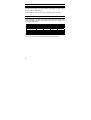
10 TRANSMITTER FUNCTION
If remote data logging is required, a 4-20 mA current loop can be connected. The current
will be proportional to the TDS value displayed on the panel and according to the
measurement range selected.
TDS Range
0.00 – 10.00 ppm
0.0 – 100.0 ppm
0.0 – 100.0 ppm
0 – 1000 ppm
0.00 – 5.00 ppt
0.00 – 10.00 ppt
0.0 – 100.0 ppt
0.0 – 100.0 ppt
Range No., R
1
2
3
4
5
6
7
8
Cell Constant
0.1
0.1
1
1
1
1
1
10
4 mA current
0.00 ppm
0.0 ppm
0.0 ppm
0 ppm
0.00 ppt
0.00 ppt
0.0 ppt
0.0 ppt
20 mA current
10.00 ppm
100.0 ppm
100.0 ppm
1000 ppm
5.0 ppt
10.0 ppt
100.0 ppt
100.0 ppt
The 4-20 mA current loop can drive a load resistance of no more than 200 Ω.
32
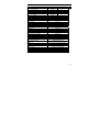
11 SPECIFICATIONS
TDS Range
0.00 – 10.00 ppm
0.0 – 100.0 ppm
0.0 – 100.0 ppm
0 – 1000 ppm
0.00 – 5.00 ppt
0.00 – 10.00 ppt
0.0 – 100.0 ppt
0.0 – 200.0 ppt
Relative Accuracy
Temperature
Resolution/Accuracy
Sensor
Temperature Comensation
Temperature Coefficient
TDS Factor
Set-point And Controller Functions
Function
Switching Conductivity Hysteresis
Contact Outputs, Controller
Switching Voltage / Current / Power
Electrical Data And Connections
Power Requirements
Signal Output / Load
Connection Terminals
Main Fuse
Resolution
Cell Constant
0.01 ppm
0.1
0.1 ppm
0.1
0.1 ppm
1
1 ppm
1
0.01 ppt
1
0.01 ppt
1
0.1 ppt
1
0.1 ppt
10
± 1 % of full scale
-10 to 110 oC
0.1 / ± 0.5 oC
Pt 100 (3-wire)
Automatic / Manual (0 to 50 oC)
0.0 to 5.0 %
0.40 to 1.00
Limit Control
5% of full scale
2 SPDT relays
Max 250 VAC / Max 3A / Max 600 VA
85 to 260 VAC, 50/60 Hz or DC
4-20 mA galvanically isolated / 200 Ω
4 Detachable connectors
(3-pin; 7-pin & 9-pin terminal blocks)
250 mA, Anti-surge (BUSSMAN S504+250mA)
Environmental Conditions
Ambient Temp. Operating Range
- 10 to 50 oC (14 to 122 oF)
Rel. Humidity
10 to 95 % (non-condensing)
Mechanical Specifications
Dimensions (Panel Housing – W x H x D)
96 x 48 x 150 mm
Weight
300g (350g boxed)
33
12 ACCESSORIES
Product Description
TDS cell, Epoxy body, Graphite sensor, w/3-wire Pt100, k = 0.1
TDS cell, Epoxy body, Graphite sensor, w/3-wire Pt100, k = 1.0
Code no.
ECCONSEN89X
ECCONSEN88X
Note: Above TDS electrodes withstand up to 3 bar pressure. These cells have
integral 1.0 m, 5-wire double-shielded open-ended cable.
Please contact your authorised distributor or dealer for the prices of
extension measuring cables and other accessories like tee joints, electrode
assembly, and calibration solutions.
34
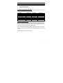
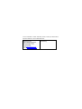
Appendix 1: Simple Explanation on the Function of Hysteresis
SP1 Set to LO
SP2 Set to HI
100
RELAYON
RELAY OFF
SP1
120
1880
1900 µS
SP2
F O R W A R D D I R EC T I O N
R E VE R S E D I R E C T I O N
The controller relay activates when the set-point is
reached. In the reverse direction, it does not deactivate when the value reaches the set-point. Instead,
it continues to be active till the value reaches the
amount set by the Hysteresis band.
HYSTERESIS BAND
Appendix 2: Factory Defaults
Resetting the controller to factory default settings (See program P8.0) clears all
calibration data and most other setup functions.
The following settings will remain unchanged:
1.
Measurement range
2.
Temperature compensation mode (ATC or MTC)
3.
Temperature offset calibration value, if in ATC mode.
Conductivity Defaults
TDS range
Set point 1
Set point 2
Temperature Defaults
Temp. Compensation mode
MTC mode
ATC mode
Temperature Coefficient
Normalization Temperature
Remains unchanged at last selected range
10% full scale / Hyst. 5% full scale / Low
90% full scale / Hyst. 5% full scale / High
remains unchanged
reset to 25oC if in MTC mode
remains at last calibration if in ATC mode
2.10 %
25.0 oC
35
Appendix 3: External Relays
The relays on the alpha TDS 200 series controller are rated for 6 amps at 110 VAC and
can be wired directly to your final control element (provided its power requirements does
not exceed this). However, to preserve the life of your controller, or if higher power is
needed, it is recommended that you use the controller relay to drive an external relay.
Diagram below shows a typical installation. Wiring should be changed appropriately if
normally closed (N.C.) operation is desired.
36
13 GENERAL INFORMATION
Warranty
Eutech Instruments warrants this product to be free from significant deviations in
material and workmanship for a period of one year from the date of purchase. If
repair is necessary and has not been the result of abuse or misuse within the
warranty period, please return by freight pre-paid and amendment will be made
without any charge. Eutech Instruments’ Customer Service Dept. will determine if
product problem is due to deviations or customer abuse. Out of warranty products
will be repaired on a charge basis.
Return of Goods
Authorisation must be obtained from Eutech Instruments’ Customer Service Dept. to
issue a RGA (Return of Goods Authorisation) number before returning items for any
reason. When applying for authorisation, please include data requiring the reason of
return. Items must be carefully packed to prevent damage in shipment and insured
against possible damage or loss. Eutech Instruments will not be responsible for any
damage resulting from careless or insufficient packing.
Warning: Shipping damage as a result of inadequate packaging is the user/distributor’s
responsibility, whoever applicable. Please follow the guidelines below before
shipment.
Guidelines for Returning Unit for Repair
Use the original packaging material, if possible when shipping the unit for repair.
Otherwise wrap it with bubble pack and use a corrugated box for better protection.
Include a brief description of any faults suspected for the convenience of Customer
Service Dept., if possible.
37
NOTES
For more information on Eutech Instruments products, contact your nearest Eutech
Instruments distributor or visit our website listed below:
Manufactured by:
Eutech Instruments Pte Ltd.
Blk 55, Ayer Rajah Crescent,
#04-16/24 Singapore 139949
Tel: (65) 6778 6876
Fax: (65) 6773 0863
E-mail: [email protected]
Web-site: http://www.eutechinst.com
Distributed by: