1
LTE TDD B2268H
V100R001C00
User Guide
Issue
01
Date
2014-01-15
HUAWEI TECHNOLOGIES CO., LTD.
Copyright © Huawei Technologies Co., Ltd. 2014. All rights reserved.
No part of this document may be reproduced or transmitted in any form or by any means without prior
written consent of Huawei Technologies Co., Ltd.
Notice
The purchased products, services and features are stipulated by the contract made between Huawei and
the customer. All or part of the products, services and features described in this document may not be
within the purchase scope or the usage scope. Unless otherwise specified in the contract, all statements,
information, and recommendations in this document are provided "AS IS" without warranties, guarantees or
representations of any kind, either express or implied.
The information in this document is subject to change without notice. Every effort has been made in the
preparation of this document to ensure accuracy of the contents, but all statements, information, and
recommendations in this document do not constitute a warranty of any kind, express or implied.
Huawei Technologies Co., Ltd.
Address:
Huawei Industrial Base
Bantian, Longgang
Shenzhen 518129
People's Republic of China
Website:
http://www.huawei.com
Issue 01 (2014-01-15)
Copyright © Huawei Technologies Co., Ltd.
i
LTE TDD B2268H
User Guide
Contents
Contents
1 Introduction.................................................................................................................................... 1
1.1 Overview ...................................................................................................................................................................... 1
1.2 Applications for the LTE Device .................................................................................................................................. 1
1.2.1 Internet Access ........................................................................................................................................................... 1
1.2.2 VoIP Features ............................................................................................................................................................. 1
1.2.3 Wireless Connection .................................................................................................................................................. 2
1.2.4 IPv6............................................................................................................................................................................ 3
1.3 The WLAN Button ....................................................................................................................................................... 3
1.4 Ways to Manage the LTE Device .................................................................................................................................. 4
1.5 Good Habits for Managing the LTE Device ................................................................................................................. 4
1.6 LEDs (Lights) ............................................................................................................................................................... 4
1.7 The RESET Button ....................................................................................................................................................... 6
2 Introducing the Web Configurator ............................................................................................ 8
2.1 Overview ...................................................................................................................................................................... 8
2.1.1 Accessing the Web Configurator ................................................................................................................................ 8
2.2 The Web Configurator Layout ...................................................................................................................................... 9
2.2.1 Title Bar ................................................................................................................................................................... 10
2.2.2 Main Window .......................................................................................................................................................... 10
2.2.3 Traffic Status ............................................................................................................................................................ 11
2.2.4 User Account ........................................................................................................................................................... 11
2.2.5 Navigation Panel ...................................................................................................................................................... 11
3 Connection Status and System Info ........................................................................................ 15
3.1 Overview .................................................................................................................................................................... 15
3.2 The Connection Status Screen .................................................................................................................................... 15
3.3 The System Info Screen .............................................................................................................................................. 16
4 Broadband .................................................................................................................................... 21
4.1 Overview .................................................................................................................................................................... 21
4.1.1 What You Need to Know ......................................................................................................................................... 21
4.1.2 Before You Begin..................................................................................................................................................... 22
4.2 Broadband Screen ....................................................................................................................................................... 22
4.2.1 WAN Interface Edit ................................................................................................................................................. 23
4.3 SIM Screen ................................................................................................................................................................. 26
Issue 01 (2014-01-15)
Copyright © Huawei Technologies Co., Ltd.
ii
LTE TDD B2268H
User Guide
Contents
5 Wireless ......................................................................................................................................... 27
5.1 Overview .................................................................................................................................................................... 27
5.1.1 Wireless Network Overview .................................................................................................................................... 27
5.1.2 Before You Begin..................................................................................................................................................... 29
5.2 The Wireless General Screen ...................................................................................................................................... 29
5.2.1 Basic (Static WEP/Shared WEP Encryption) .......................................................................................................... 32
5.2.2 More Secure (WPA(2)-PSK) ................................................................................................................................... 33
5.2.3 WPA(2) Authentication ............................................................................................................................................ 34
5.3 The More AP Screen ................................................................................................................................................... 36
5.3.1 Edit More AP ........................................................................................................................................................... 37
5.4 The WPS Screen ......................................................................................................................................................... 38
5.5 The WMM Screen ...................................................................................................................................................... 40
5.6 Scheduling Screen ...................................................................................................................................................... 41
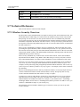
5.7 Technical Reference .................................................................................................................................................... 42
5.7.1 Wireless Security Overview..................................................................................................................................... 42
5.7.2 Signal Problems ....................................................................................................................................................... 44
5.7.3 BSS .......................................................................................................................................................................... 44
5.7.4 MBSSID .................................................................................................................................................................. 45
5.7.5 WiFi Protected Setup (WPS) ................................................................................................................................... 45
5.7.5.1 Push Button Configuration ................................................................................................................................... 46
5.7.5.2 PIN Configuration ................................................................................................................................................ 46
5.7.5.3 How WPS Works .................................................................................................................................................. 48
5.7.5.4 Example WPS Network Setup .............................................................................................................................. 49
5.7.5.5 Limitations of WPS .............................................................................................................................................. 51
6 Home Networking ...................................................................................................................... 53
6.1 Overview .................................................................................................................................................................... 53
6.1.1 What You Need To Know ........................................................................................................................................ 53
6.1.1.1 About LAN IP Address ......................................................................................................................................... 53
6.1.1.2 About UPnP .......................................................................................................................................................... 54
6.2 The LAN Setup Screen ............................................................................................................................................... 54
6.3 The Static DHCP Screen ............................................................................................................................................. 56
6.3.1 Before You Begin..................................................................................................................................................... 56
6.4 The UPnP Screen ........................................................................................................................................................ 58
6.5 The File Sharing Screen .............................................................................................................................................. 58
6.6 The Media Server Screen ............................................................................................................................................ 60
7 Routing .......................................................................................................................................... 63
7.1 Overview .................................................................................................................................................................... 63
7.2 Configuring Static Route ............................................................................................................................................ 63
7.2.1 Add/Edit Static Route .............................................................................................................................................. 64
8 Network Address Translation (NAT) ..................................................................................... 66
Issue 01 (2014-01-15)
Copyright © Huawei Technologies Co., Ltd.
iii
LTE TDD B2268H
User Guide
Contents
8.1 Overview .................................................................................................................................................................... 66
8.1.1 What You Need To Know ........................................................................................................................................ 66
8.2 The Port Forwarding Screen ....................................................................................................................................... 67
8.2.1 The Port Forwarding Screen .................................................................................................................................... 67
8.2.2 The Port Forwarding Edit Screen ............................................................................................................................ 68
8.3 The DMZ Screen ........................................................................................................................................................ 70
8.4 The Sessions Screen.................................................................................................................................................... 70
8.5 The ALG Screen ......................................................................................................................................................... 71
8.6 Technical Reference .................................................................................................................................................... 71
8.6.1 NAT Definitions ....................................................................................................................................................... 72
8.6.2 What NAT Does ....................................................................................................................................................... 72
8.6.3 How NAT Works[h1] ............................................................................................................................................... 72
9 Dynamic DNS .............................................................................................................................. 74
9.1 Overview .................................................................................................................................................................... 74
9.1.1 What You Need To Know ........................................................................................................................................ 74
9.2 The Dynamic DNS Screen .......................................................................................................................................... 74
10 Firewall........................................................................................................................................ 76
10.1 Overview .................................................................................................................................................................. 76
10.1.1 What You Need to Know ....................................................................................................................................... 76
10.2 The General Screen ................................................................................................................................................... 77
10.3 The Services Screen .................................................................................................................................................. 78
10.3.1 The Add New Services Entry Screen ..................................................................................................................... 79
10.4 The Access Control Screen ....................................................................................................................................... 80
10.4.1 The Add New ACL Rule/Edit Screen .................................................................................................................... 81
10.5 The DoS Screen ........................................................................................................................................................ 83
10.6 Firewall Technical Reference.................................................................................................................................... 83
10.6.1 Guidelines For Enhancing Security With Your Firewall ........................................................................................ 83
10.6.2 Security Considerations ......................................................................................................................................... 84
11 MAC Filter .................................................................................................................................. 85
11.1 Overview................................................................................................................................................................... 85
11.1.1 What You Need to Know ....................................................................................................................................... 85
11.2 The MAC Filter Screen ............................................................................................................................................. 85
12 Parental Control......................................................................................................................... 87
12.1 Overview .................................................................................................................................................................. 87
12.2 The Parental Control Screen ..................................................................................................................................... 87
12.2.1 Add/Edit a Parental Control Rule .......................................................................................................................... 88
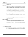
13 VoIP ............................................................................................................................................. 91
13.1 Overview .................................................................................................................................................................. 91
13.1.1 What You Need to Know ....................................................................................................................................... 91
13.1.2 Before You Begin................................................................................................................................................... 92
Issue 01 (2014-01-15)
Copyright © Huawei Technologies Co., Ltd.
iv
LTE TDD B2268H
User Guide
Contents
13.2 The SIP Service Provider Screen .............................................................................................................................. 93
13.3 The SIP Account Screen ........................................................................................................................................... 99
13.3.1 Edit SIP Account .................................................................................................................................................. 100
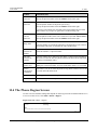
13.4 The Phone Region Screen ....................................................................................................................................... 103
13.5 The Call Rule Screen .............................................................................................................................................. 104
13.6 Technical Reference ................................................................................................................................................ 105
13.6.1 VoIP ..................................................................................................................................................................... 105
13.6.2 SIP ....................................................................................................................................................................... 106
13.6.3 Quality of Service (QoS) ..................................................................................................................................... 111
13.6.4 Phone Services Overview .................................................................................................................................... 111
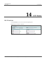
14 LTE Status ................................................................................................................................. 115
14.1 Overview ................................................................................................................................................................ 115
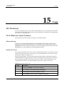
15 Logs ............................................................................................................................................ 116
15.1 Overview ................................................................................................................................................................ 116
15.1.1 What You Need To Know .................................................................................................................................... 116
15.2 The System Log Screen .......................................................................................................................................... 117
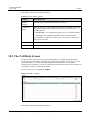
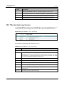
15.3 The Phone Log Screen ............................................................................................................................................ 118
15.4 The VoIP Call History Screen ................................................................................................................................. 118
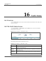
16 Traffic Status ............................................................................................................................ 120
16.1 Overview ................................................................................................................................................................ 120
16.2 The WAN Status Screen.......................................................................................................................................... 120
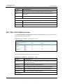
16.3 The LAN Status Screen .......................................................................................................................................... 121
16.4 The NAT Status Screen ........................................................................................................................................... 122
16.5 The VoIP Status Screen ........................................................................................................................................... 123
17 User Account ............................................................................................................................ 125
17.1 Overview ................................................................................................................................................................ 125
17.2 The User Account Screen........................................................................................................................................ 125
18 Remote MGMT ........................................................................................................................ 127
18.1 Overview ................................................................................................................................................................ 127
18.1.1 What You Need to Know ..................................................................................................................................... 127
18.2 The Remote MGMT Screen .................................................................................................................................... 127
19 System ....................................................................................................................................... 129
19.1 Overview ................................................................................................................................................................ 129
19.1.1 What You Need to Know ..................................................................................................................................... 129
19.2 The System Screen.................................................................................................................................................. 129
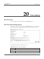
20 Time Setting ............................................................................................................................. 131
20.1 Overview ................................................................................................................................................................ 131
20.2 The Time Setting Screen ......................................................................................................................................... 131
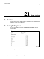
21 Log Setting ................................................................................................................................ 133
Issue 01 (2014-01-15)
Copyright © Huawei Technologies Co., Ltd.
v
LTE TDD B2268H
User Guide
Contents
21.1 Overview ................................................................................................................................................................ 133
21.2 The Log Setting Screen ........................................................................................................................................... 133
22 Software Upgrade ................................................................................................................... 135
22.1 Overview ................................................................................................................................................................ 135
22.2 FOTA Upgrade ........................................................................................................................................................ 135
22.3 The Software Upgrade ............................................................................................................................................ 137
23 Backup/Restore ........................................................................................................................ 140
23.1 Overview ................................................................................................................................................................ 140
23.2 The Backup/Restore Screen .................................................................................................................................... 140
23.3 The Reboot Screen .................................................................................................................................................. 142
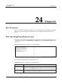
24 Diagnostic ................................................................................................................................. 143
24.1 Overview ................................................................................................................................................................ 143
24.2 The Ping/TraceRoute Screen .................................................................................................................................. 143
25 Troubleshooting ...................................................................................................................... 144
25.1 Overview ................................................................................................................................................................ 144
25.2 Power, Hardware Connections, and LEDs .............................................................................................................. 144
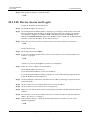
25.3 LTE Device Access and Login ................................................................................................................................ 145
25.4 Internet Access ........................................................................................................................................................ 146
25.5 Wireless Internet Access ......................................................................................................................................... 147
25.6 Phone Calls and VoIP.............................................................................................................................................. 148
25.7 UPnP ....................................................................................................................................................................... 148
Issue 01 (2014-01-15)
Copyright © Huawei Technologies Co., Ltd.
vi
LTE TDD B2268H
User Guide
1 Introduction
1
Introduction
1.1 Overview
The Device is an LTE (Long Term Evolution) device including an outdoor unit (ODU) and an
indoor unit (IDU). The LTE Device also provides a complete security solution with a robust
firewall based on Stateful Packet Inspection (SPI) technology and Denial of Service (DoS).
See the chapter on product specifications for a full list of features.
1.2 Applications for the LTE Device
Here are some examples for which the LTE Device is well suited.
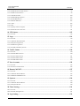
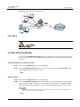
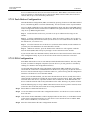
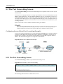
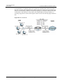
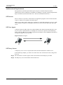
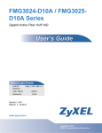
1.2.1 Internet Access
Your LTE Device provides Internet access by connecting to an LTE network wirelessly. Your
LTE Device supports LTE frequency bands 38, 40, 42, and 43 although the bands it actually
uses depends on your LTE service provider. Computers can connect to the LTE Device's
ETHERNET ports (or wirelessly).
Figure 1-1 LTE Device's Internet Access Application
1.2.2 VoIP Features
Issue 01 (2014-01-15)
Copyright © Huawei Technologies Co., Ltd.
1
LTE TDD B2268H
User Guide
1 Introduction
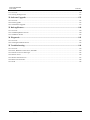
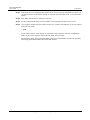
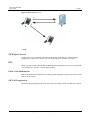
VoIP is not supported
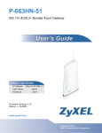
You can register one SIP (Session Initiation Protocol) profile with one account for that profile
and use the LTE Device to make and receive VoIP telephone calls:
Figure 1-2 LTE Device's VoIP Application
The LTE Device sends your call to a VoIP service provider's SIP server which forwards your
calls to either VoIP or PSTN phones. Enable the LTE Device's SIP ALG feature to support SIP
phones and IAD devices on the LAN.
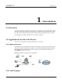
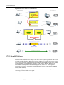
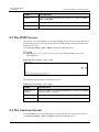
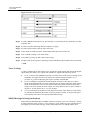
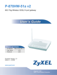
1.2.3 Wireless Connection
By default, the wireless LAN (WLAN) is enabled on the LTE Device. Once Wireless is enabled,
IEEE 802.11b/g/n compliant clients can wirelessly connect to the LTE Device to access
network resources. You can set up a wireless network with WPS (WiFi Protected Setup) or
manually add a client to your wireless network.
Issue 01 (2014-01-15)
Copyright © Huawei Technologies Co., Ltd.
2
LTE TDD B2268H
User Guide
1 Introduction
Figure 1-3 Wireless Connection Application
1.2.4 IPv6
IPv6 is not support
1.3 The WLAN Button
You can use the WIRELESS On/Off button on top of the device to turn the wireless LAN on or
off. You can also use it to activate WPS in order to quickly set up a wireless network with strong
security.
Turn the Wireless LAN On or Off
Step 1 Make sure the PWR/SYS LED is on (not blinking).
Step 2 Press the WIRELESS On/Off button for one second and release it. The WLAN/WPS LED
should change from on to off or vice versa.
----End
Activate WPS
Step 1 Make sure the PWR/SYS LED is on (not blinking).
Step 2 Press the WIRELESS On/Off button for more than five seconds and release it. Press the WPS
button on another WPS-enabled device within range of the LTE Device. The WLAN/ WPS
LED should flash while the LTE Device sets up a WPS connection with the wireless device.
You must activate WPS in the LTE Device and in another wireless device within two minutes of each
other. See Section 5.7.6 for more information.
----End
Issue 01 (2014-01-15)
Copyright © Huawei Technologies Co., Ltd.
3
LTE TDD B2268H
User Guide
1 Introduction
1.4 Ways to Manage the LTE Device
Web Configurator is for management of the LTE Device using a (supported) web browser.
1.5 Good Habits for Managing the LTE Device
Do the following things regularly to make the LTE Device more secure and to manage the LTE
Device more effectively.
Change the password. Use a password that's not easy to guess and that consists of different
types of characters, such as numbers and letters.
Write down the password and put it in a safe place.
Back up the configuration (and make sure you know how to restore it). Restoring an earlier
working configuration may be useful if the device becomes unstable or even crashes. If
you forget your password to access the Web Configurator, you will have to reset the LTE
Device to its factory default settings. If you backed up an earlier configuration file, you
would not have to totally re-configure the LTE Device. You could simply restore your last
configuration. Keep in mind that backing up a configuration file will not back up
passwords used to set up your VoIP account. Write down any information your ISP
provides you.
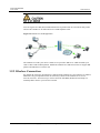
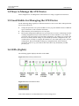
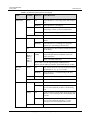
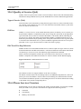
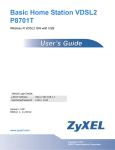
1.6 LEDs (Lights)
The following graphic displays the labels of the LEDs.
Figure 1-4 LEDs on the top of the Device
Figure 1-5 LEDs on the Ethernet Ports
None of the LEDs are on if the LTE Device is not receiving power.
Issue 01 (2014-01-15)
Copyright © Huawei Technologies Co., Ltd.
4
LTE TDD B2268H
User Guide
1 Introduction
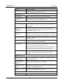
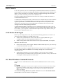
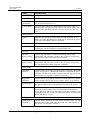
Table 1-1 LED Descriptions (From Left To Right)
LED
COLOR
STATUS
DESCRIPTION
PWR/SYS
Green
On
The LTE Device is receiving power and ready for
use.
Blinking
The LTE Device is booting up.
On
The LTE Device detected an error while
self-testing, or there is a device malfunction.
Blinking
The LTE Device is upgrading the firmware.
Red
Off
LINK
The LTE Device is not receiving power.
Green
On
The LTE Device has an LTE connection on the
WAN.
Blinking
The LTE Device is searching for a frequency
channel or is performing network entry.
The LTE Device does not have an LTE connection
on the WAN.
Off
LTE RSSI
Green
(RSSI_1,
RSSI_2,
RSSI_3,
RSSI_4,
RSSI_5)
No Signal
LEDS
There are 5 signal LEDs to show the Received
Signal Strength Indication (RSSI) of the LTE
radio connection.
There is no LTE connection.
Refer Table 1-2 LTE Signal Strength LED Definition
Please note the ODU presents the same LED behavior as IDU.
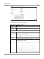
WLAN/
WPS
Green
Orange
On
The wireless network is activated and is operating
in IEEE 802.11 "b", "g" or "n" mode.
Blinking
The LTE Device is communicating with other
wireless clients.
Blinking
The LTE Device is setting up a WPS connection.
Off
PHONE
Green
Orange
Off
Issue 01 (2014-01-15)
The wireless network is not activated.
On
A SIP account is registered for the phone port.
Blinking
A telephone connected to the phone port has its
receiver off of the hook or there is an incoming
call.
On
A SIP account is registered for the phone port and
there is a voice message in the corresponding SIP
account.
Blinking
A telephone connected to the phone port has its
receiver off of the hook and there is a voice
message in the corresponding SIP account.
The phone port does not have a SIP account
Copyright © Huawei Technologies Co., Ltd.
5
LTE TDD B2268H
User Guide
1 Introduction
LED
COLOR
STATUS
DESCRIPTION
registered.
ETHERNET
1-2
Yellow
(Giga
Ethernet)
Green
(Fast
Ethernet)
On
The LTE Device has a successful 1000 Mbps
Ethernet connection with a device on the Local
Area Network (LAN).
Blinking
The LTE Device is sending or receiving data
to/from the LAN at 1000 Mbps.
On
The LTE Device has a successful 10/100 Mbps
Ethernet connection with a device on the Local
Area Network (LAN).
Blinking
The LTE Device is sending or receiving data
to/from the LAN at 10/100 Mbps.
The LTE Device does not have an Ethernet
connection with the LAN.
Off
USB
Green
On
USB Storage device is plugged in.
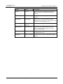
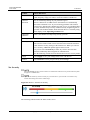
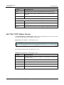
Table 1-2 Signal Strength LED Definition
-114 <= RSRP
<
-109 <= RSRP
<
-109
-104
0
1
-2.8 <= SINR <
1.2
0
1.2 <= SINR <
4.8
RSRP: dBm
RSRP <
SINR: dB
-114
SINR < -2.8
RSRP >=
-104 <= RSRP
< -94
-94 <= RSRP <
-84
1
1
1
1
1
2
2
2
2
0
1
2
3
3
3
4.8 <= SINR <
13.2
0
1
2
3
4
4
SINR >= 13.2
0
1
2
3
4
5
-84
Refer to the Quick Start Guide for information on hardware connections.
1.7 The RESET Button
If you forget your password or cannot access the web configurator, you will need to use the
RESET button at the back of the device to reload the factory-default configuration file. This
means that you will lose all configurations that you had previously and the web access
password will be reset to the default.
Step 1 Make sure the POWER LED is on (not blinking).
Issue 01 (2014-01-15)
Copyright © Huawei Technologies Co., Ltd.
6
LTE TDD B2268H
User Guide
1 Introduction
Step 2 To set the device back to the factory default settings, press the RESET button for 5 seconds or
until the POWER LED begins to blink and then release it. When the POWER LED begins to
blink, the defaults have been restored and the device will restart to load the default settings.
----End
Issue 01 (2014-01-15)
Copyright © Huawei Technologies Co., Ltd.
7
LTE TDD B2268H
User Guide
2 Introducing the Web Configurator
2
Introducing the Web Configurator
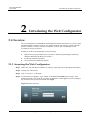
2.1 Overview
The web configurator is an HTML-based management interface that allows easy device setup
and management via Internet browser. Use Internet Explorer 6.0 and later versions, Mozilla
Firefox 3 and later versions, or Safari 2.0 and later versions. The recommended screen
resolution is 1024 by 768 pixels.
In order to use the web configurator you need to allow:
Web browser pop-up windows from your device. Web pop-up blocking is enabled by
default in Windows XP SP (Service Pack) 2.
JavaScript (enabled by default).
Java permissions (enabled by default).
2.1.1 Accessing the Web Configurator
Step 1 Make sure your LTE Device hardware is properly connected (refer to the Quick Start Guide).
Step 2 Launch your web browser.
Step 3 Type "192.168.1.1" as the URL.
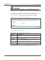
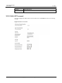
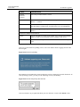
Step 4 A password screen displays. Type "admin" as the default Username and "LTEcpe" as the
default password to access the device's Web Configurator. Click Login. If you have changed
the password, enter your password and click Login.
Figure 2-1 Password Screen
Issue 01 (2014-01-15)
Copyright © Huawei Technologies Co., Ltd.
8
LTE TDD B2268H
User Guide
2 Introducing the Web Configurator
For security reasons, the LTE Device automatically logs you out if you do not use the web configurator
for five minutes (default). If this happens, log in again.
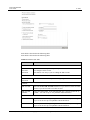
Step 5 The following screen displays if you have not yet changed your password. It is strongly
recommended you change the default password. Enter a new password, retype it to confirm and
click Apply; alternatively click Skip to proceed to the main menu if you do not want to change
the password now.
Figure 2-2 Change Password Screen
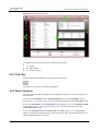
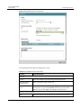
Step 6 The Connection Status screen appears.
Figure 2-3 Connection Status (The screenshot uses B2268H as an example.)
Step 7 Click System Info to display the System Info screen, where you can view the LTE Device's
interface and system information.
----End
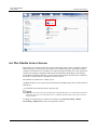
2.2 The Web Configurator Layout
Click Connection Status > System Info to show the following screen. (See 3.3 The System
Info Screen for more information.)
Issue 01 (2014-01-15)
Copyright © Huawei Technologies Co., Ltd.
9
LTE TDD B2268H
User Guide
2 Introducing the Web Configurator
Figure 2-4 Web Configurator Layout
As illustrated above, the main screen is divided into these parts:
A - title bar
B - main window
C - navigation panel
2.2.1 Title Bar
The title bar shows the following icon in the upper right corner.
Click this icon to log out of the Web Configurator.
2.2.2 Main Window
The main window displays information and configuration fields. It is discussed in the rest of
this document.
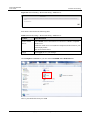
After you click System Info on the Connection Status screen, the System Info screen is
displayed. See 3.3 The System Info Screen for more information about the System Info screen.
If you click LAN Device on the System Info screen (A in Figure 2-4), the Connection Status
screen appears. See 3.2 The Connection Status Screen for more information about the
Connection Status screen.
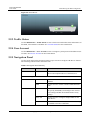
If you click Virtual Device on the System Info screen (B in Figure 2-4), a visual graphic
appears, showing the connection status of the LTE Device's ports. The connected ports are in
color and disconnected ports are gray.
Issue 01 (2014-01-15)
Copyright © Huawei Technologies Co., Ltd.
10
LTE TDD B2268H
User Guide
2 Introducing the Web Configurator
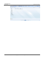
Figure 2-5 Virtual Device
2.2.3 Traffic Status
Use the Maintenance > Traffic Status screens to look at network traffic status and statistics of
the WAN, LAN interfaces and NAT. See 19 Traffic Status for more information.
2.2.4 User Account
Use the Maintenance > User Accounts screen to configure system password for different user
accounts. See 20 User Account for more information.
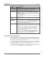
2.2.5 Navigation Panel
Use the menu items on the navigation panel to open screens to configure LTE Device features.
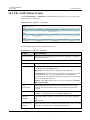
The following table describes each menu item.
Table 2-1 Navigation Panel Summary
LINK
TAB
FUNCTION
Connection Status
NA
This screen shows the network status of the LTE
Device and computers/devices connected to it.
Broadband
Use this screen to view or edit an LTE WAN
interface
SIM
Use this screen to enable or disable SIM PIN/PUK
code.
General
Use this screen to turn the wireless connection on or
off, specify the SSID(s) and configure the wireless
LAN settings and WLAN authentication/security
settings.
More AP
Use this screen to configure multiple BSSs on the
LTE Device.
WPS
Use this screen to use WPS (Wi-Fi Protected Setup)
to establish a wireless connection.
Network Setting
Broadband
Wireless
Issue 01 (2014-01-15)
Copyright © Huawei Technologies Co., Ltd.
11
LTE TDD B2268H
User Guide
2 Introducing the Web Configurator
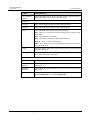
LINK
TAB
FUNCTION
WMM
Use this screen to enable or disable Wi-Fi
MultiMedia (WMM).
Scheduling
Use this screen to configure when the LTE Device
enables or disables the wireless LAN.
LAN Setup
Use this screen to configure LAN IPv4 TCP/IP
settings, and other advanced properties.
Static DHCP
Use this screen to assign specific IP addresses to
individual MAC addresses.
UPnP
Use this screen to enable the UPnP function.
File Sharing
Use this screen to enable file sharing via the LTE
Device.
Media Server
Use this screen to use the LTE Device as a media
server.
Static Route
Static Route
Use this screen to view and set up static routes for
IPv4 networks on the LTE Device.
NAT
Port
Forwarding
Use this screen to make your local servers visible to
the outside world.
DMZ
Use this screen to configure the IP address of the
LTE Device's DMZ interface.
Sessions
Use this screen to limit the number of NAT sessions
a single client can establish.
ALG
Use this screen to enable or disable the SIP ALG
function which allows SIP calls to pass through
NAT.
Dynamic DNS
Use this screen to allow a static hostname alias for a
dynamic IP address.
General
Use this screen to activate/deactivate the firewall for
the IPv4 network.
Services
Use this screen to view and configure services for
the IPv4 network.
Access
Control
Use this screen to view and configure filter rules for
incoming and outgoing traffic.
DoS
Use this screen to activate/deactivate Denial of
Service (DoS) protection.
MAC Filter
MAC Filter
Use this screen to allow specific devices to access
the LTE Device.
Parental Control
Parental
Control
Use this screen to define time periods and days
during which the LTE Device performs parental
Home Networking
Dynamic DNS
Security
Firewall
Issue 01 (2014-01-15)
Copyright © Huawei Technologies Co., Ltd.
12
LTE TDD B2268H
User Guide
2 Introducing the Web Configurator
LINK
TAB
FUNCTION
control and/ or block web sites with the specific
URL.
VoIP
SIP Service
Provider
Use this screen to configure your LTE Device's
Voice over IP settings.
SIP Account
Use this screen to set up information about your SIP
account and configure audio settings such as volume
levels for the phones connected to the LTE Device.
Phone Device
Use this screen you will see which phone(s) will ring
when a specific SIP account number receive an
incoming call; and which SIP account number will
be used when a specific phone is used to make an
outgoing call.
Region
Use this screen to select your location.
Speed Dial
Use this screen to configure speed dial for SIP phone
numbers that you call often.
LTE Status
LTE Status
Use this screen to view detail LTE status
information.
Log
System Log
Use this screen to view the system logs for the
categories that you select.
Phone Log
Use this screen to view the LTE Device's phone
logs.
VoIP Call
History
Use this screen to view the LTE Device's VoIP call
history.
WAN
Use this screen to view the status of all network
traffic going through the WAN port of the LTE
Device.
LAN
Use this screen to view the status of all network
traffic going through the LAN ports of the LTE
Device.
NAT
Use this screen to view the status of NAT sessions
on the LTE Device.
VoIP Status
Use this screen to view the SIP, phone, and call
status of the LTE Device.
SIP
Phone
Call Rule
System Monitor
Traffic Status
VoIP Status
Maintenance
Users Account
Users Account
Use this screen to configure the passwords your
user accounts.
Remote MGMT
Remote MGMT
Use this screen to enable specific traffic directions
for network services.
Issue 01 (2014-01-15)
Copyright © Huawei Technologies Co., Ltd.
13
LTE TDD B2268H
User Guide
2 Introducing the Web Configurator
LINK
TAB
System
System
Use this screen to configure the LTE Device's
name, domain name, management inactivity
time-out.
Time Setting
Time Setting
Use this screen to change your LTE Device's time
and date.
Log Setting
Log Setting
Use this screen to select which logs and/or
immediate alerts your device is to record. You can
also set it to e- mail the logs to you.
Software Upgrade
Software
Upgrade
Use this screen to upload firmware to your device.
Backup/Restore
Backup/Restore
Use this screen to backup and restore your
device's configuration (settings) or reset the
factory default settings.
Reboot
Reboot
Use this screen to reboot the LTE Device without
turning the power off.
Diagnostic
Ping/ TraceRoute
Use this screen to test the connections to other
devices.
Issue 01 (2014-01-15)
FUNCTION
Copyright © Huawei Technologies Co., Ltd.
14
LTE TDD B2268H
User Guide
3 Connection Status and System Info
3
Connection Status and System Info
3.1 Overview
After you log into the web configurator, the Connection Status screen appears. This shows the
network connection status of the LTE Device and clients connected to it.
Use the System Info screen to look at the current status of the device, system resources,
interfaces (LAN, WAN and WLAN), and SIP accounts. You can also register and unregister SIP
accounts.
If you click Virtual Device on the System Info screen, a visual graphic appears, showing the
connection status of the LTE Device's ports. See 2.2.2 Main Window for more information.
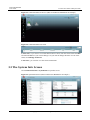
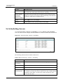
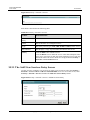
3.2 The Connection Status Screen
Use this screen to view the network connection status of the device and its clients. A warning
message appears if there is a connection problem.
If you prefer to view the status in a list, click List View in the Viewing mode selection box. You
can configure how often you want the LTE Device to update this screen in Refresh Interval.
Issue 01 (2014-01-15)
Copyright © Huawei Technologies Co., Ltd.
15
LTE TDD B2268H
User Guide
3 Connection Status and System Info
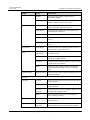
Figure 3-1 Connection Status: Icon View (This screenshot uses B2268H for an example.)
Figure 3-2 Connection Status: List View
In Icon View, if you want to view information about a client, click the client's name and Info.
Click the IP address if you want to change it. If you want to change the name or icon of the
client, click Change name/icon.
In List View, you can also view the client's information.
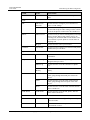
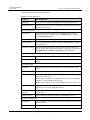
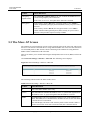
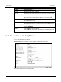
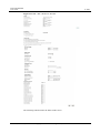
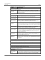
3.3 The System Info Screen
Click Connection Status > System Info to open this screen.
Figure 3-3 System Info Screen (This screenshot uses B2268S for an example.)
Issue 01 (2014-01-15)
Copyright © Huawei Technologies Co., Ltd.
16
LTE TDD B2268H
User Guide
3 Connection Status and System Info
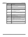
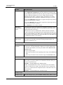
Each field is described in the following table.
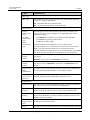
Table 3-1 System Info Screen
LABEL
DESCRIPTION
Language
Select the web configurator language from the drop-down list box.
Refresh Interval
Select how often you want the LTE Device to update this screen from
the drop-down list box.
Device Information
Host Name
This field displays the LTE Device system name. It is used for
identification. You can change this in the Maintenance > System
screen's Host Name field.
Model Name
This is the model name of your device.
MAC Address
This is the MAC (Media Access Control) or Ethernet address unique to
your LTE Device.
Software Version
This field displays the current version of the firmware inside the
device. It also shows the date the firmware version was created. Go to
the Maintenance > Firmware Upgrade screen to change it.
WAN Information
Mode
This is the method of encapsulation used by your ISP.
IP Address
This field displays the current IP address of the LTE Device in the
WAN.
LAN Information
IP Address
This field displays the current IP address of the LTE Device in the
LAN.
IP Subnet Mask
This field displays the current subnet mask in the LAN.
DHCP Server
This field displays what DHCP services the LTE Device is providing
to the LAN. Choices are:
Server - The LTE Device is a DHCP server in the LAN. It assigns IP
addresses to other computers in the LAN.
None - The LTE Device is not providing DHCP services to the LAN.
ULA IPv6 Address
This field displays the static IPv6 address and the prefix length the
LTE Device uses for the LAN IPv6 address.
Link-Local IPv6
Address
This field displays a unique address the LTE Device generates itself
for the LAN.
DHCPv6 Server
This field displays the IPv6 IP address of the DHCPv6 server.
IP Alias 1 Information
IP Address
This field displays the IP address for another logical LAN interface on
the LTE Device.
IP Subnet Mask
This field displays the subnet mask of the logical LAN network.
Issue 01 (2014-01-15)
Copyright © Huawei Technologies Co., Ltd.
17
LTE TDD B2268H
User Guide
3 Connection Status and System Info
LABEL
DESCRIPTION
WLAN Information
Channel
This is the channel number used by the LTE Device now.
WPS Status
Configured displays when a wireless client has connected to the LTE
Device or WPS is enabled and wireless or wireless security settings
have been configured. Unconfigured displays if WPS is disabled or
wireless security settings have not been configured.
SSID (1~4) Information
SSID
This is the descriptive name used to identify the LTE Device in the
wireless LAN.
Status
This shows whether or not the SSID is enabled (on).
Security Mode
This displays the type of security the LTE Device is using in the
wireless LAN.
LTE Status
Status
This displays 4G LTE if there is an LTE connection, otherwise, it
displays N/A.
SIM Card Status
This displays PIN disable if SIM card needs PIN or PUK to unlock, it
displays PIN required or PUK required.
Signal Strength
This displays the strength of the LTE connection that the LTE Device
has with the base station which is also known as eNodeB or eNB.
Service Provider
This displays the service provider's name of the connected LTE
Network.
Frequency Band
This displays LTE if there is an LTE connection.
Connection
Uptime
This displays how long the LTE connection has been available since it
was last established successfully.
RSRP
This displays the RSRP strength of the LTE connection that the LTE
Device has with the base station which is also known as eNodeB or
eNB.
SINR
This displays the SINR strength of the LTE connection that the LTE
Device has with the base station which is also known as eNodeB or
eNB.
ODU F/W Version
This displays the firmware version of the outdoor unit.
Module F/W
Version
This displays the firmware version of LTE module.
IMEI
This displays the LTE Device’s International Mobile Equipment
Identity number (IMEI). An IMEI is a unique ID used to identify a
mobile device.
IMSI
This displays the International Mobile Subscriber Identity (IMSI) of
the SIM card inserted in the outdoor unit. An IMSI is a unique ID used
Issue 01 (2014-01-15)
Copyright © Huawei Technologies Co., Ltd.
18
LTE TDD B2268H
User Guide
3 Connection Status and System Info
LABEL
DESCRIPTION
to identify a mobile subscriber in a mobile network.
Interface Status
Interface
This column displays each interface the LTE Device has.
Status
This field indicates whether or not the LTE Device is using the
interface.
For the LTE WAN interface, this field displays Up when the LTE
Device is connected to an LTE network and Down when the LTE
Device does not have an LTE connection.
For the LAN interface, this field displays Up when the LTE Device is
using the interface and Down when the LTE Device is not using the
interface.
For the WLAN interface, it displays Up when WLAN is enabled or
Down when WLAN is disabled.
For the LTE WAN interface, this displays 4G LTE if there is an LTE
connection.
Rate
For the LAN interface, this displays the port speed and duplex setting.
For the WLAN interface, it displays the maximum transmission rate
when WLAN is enabled or N/A when WLAN is disabled.
System Status
System Up Time
This field displays how long the LTE Device has been running since it
last started up. The LTE Device starts up when you plug it in, when
you restart it (Maintenance > Reboot), or when you reset it (see
Section 1.7).
Current Date/Time
This field displays the current date and time in the LTE Device. You
can change this in Maintenance > Time Setting.
System Resource
CPU Usage
This field displays what percentage of the LTE Device's processing
ability is currently used. When this percentage is close to 100%, the
LTE Device is running at full load, and the throughput is not going to
improve anymore. If you want some applications to have more
throughput, other applications should be turned off.
Memory Usage
This field displays what percentage of the LTE Device's memory is
currently used. Usually, this percentage should not increase much. If
memory usage does get close to 100%, the LTE Device is probably
becoming unstable, and you should restart the device. See Chapter 23,
or turn off the device (unplug the power) for a few seconds.
Registration Status
Account
This column displays each SIP account in the LTE Device.
Action
This field displays the current registration status of the SIP account.
You have to register SIP accounts with a SIP server to use VoIP.
If the SIP account is already registered with the SIP server,
Issue 01 (2014-01-15)
Click Unregister to delete the SIP account's registration in the SIP
Copyright © Huawei Technologies Co., Ltd.
19
LTE TDD B2268H
User Guide
3 Connection Status and System Info
LABEL
DESCRIPTION
server. This does not cancel your SIP account, but it deletes the
mapping between your SIP identity and your IP address or domain
name.
The second field displays Registered.
If the SIP account is not registered with the SIP server,
Click Register to have the LTE Device attempt to register the SIP
account with the SIP server.
The second field displays the reason the account is not registered.
Inactive - The SIP account is not active. You can activate it in VoIP >
SIP > SIP Settings.
Register Fail - The last time the LTE Device tried to register the SIP
account with the SIP server, the attempt failed. The LTE Device
automatically tries to register the SIP account when you turn on the
LTE Device or when you activate it.
Account Status
This field shows Active when the SIP account has been registered and
ready for use or In-Active when the SIP account is not yet registered.
URI
This field displays the account number and service domain of the SIP
account. You can change these in VoIP > SIP > SIP Settings.
Issue 01 (2014-01-15)
Copyright © Huawei Technologies Co., Ltd.
20
LTE TDD B2268H
User Guide
4 Broadband
4
Broadband
4.1 Overview
This chapter discusses the LTE Device's Broadband screens. Use these screens to configure
your LTE Device for Internet access.
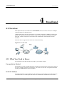
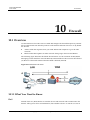
A WAN (Wide Area Network) connection is an outside connection to another network or the
Internet. It connects your private networks, such as a LAN (Local Area Network) and other
networks, so that a computer in one location can communicate with computers in other
locations.
This LTE Device supports LTE connection for the WAN only.
Figure 4-1 LAN and WAN
4.1.1 What You Need to Know
The following terms and concepts may help as you read this chapter.
Encapsulation Method
Encapsulation is used to include data from an upper layer protocol into a lower layer protocol.
To set up a WAN connection to the Internet, you need to use the same encapsulation method
used by your ISP (Internet Service Provider).
WAN IP Address
The WAN IP address is an IP address for the LTE Device, which makes it accessible from an
outside network. It is used by the LTE Device to communicate with other devices in other
Issue 01 (2014-01-15)
Copyright © Huawei Technologies Co., Ltd.
21
LTE TDD B2268H
User Guide
4 Broadband
networks. It can be static (fixed) or dynamically assigned by the ISP each time the LTE Device
tries to access the Internet.
If your ISP assigns you a static WAN IP address, they should also assign you the subnet mask
and DNS server IP address(es).
APN
Access Point Name (APN) is a unique string which indicates an LTE network.
4.1.2 Before You Begin
You may need to know your Internet access settings such as LTE APN, WAN IP address and
SIM card's PIN code if the INTERNET light on your LTE Device is off. Get this information
from your service provider.
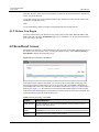
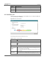
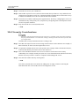
4.2 Broadband Screen
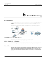
The LTE Device must have a WAN interface to allow users to use the LTE connection to access
the Internet. Use this screen to view or modify the WAN interface. Click Network Setting >
Broadband to display the following screen.
Figure 4-2 Network Setting >Broadband
If the LTE network supports dual APNs, you can set up the second APN via this page. The
detail setting will be provided from your service provider. The second APN is dedicated for
transmitting VoIP traffic only. When the second APN is enabled (see Figure 4-2) and its NAT is
disabled (see Figure 4-3), the LTE Device forwards all VoIP related traffic received from the
built-in FXS port and SIP phones or IAD devices connected to the LAN to the connection. The
following table describes the fields in this screen.
Table 4-1 Network Setting > Broadband
LABEL
DESCRIPTION
LTE Antenna
If your LTE Device has an external antenna, you may choose to use it
instead of the internal one.
Antenna
Mode
If you connect an external antenna to the LTE Device, select External
Antenna here to have the LTE Device use it instead of the internal antenna.
Apply
Click this to save the change in this section.
Issue 01 (2014-01-15)
Copyright © Huawei Technologies Co., Ltd.
22
LTE TDD B2268H
User Guide
4 Broadband
LABEL
DESCRIPTION
Cancel
Click this to restore your previously saved settings in this section.
Internet Setup
Enabled
This shows the APN service is activated or inactivated.
Name
This is the service name of the connection.
IPv4/IPv6
This shows whether the connection uses IPv6 or IPv4.
Mode
APN
This is the name of the LTE network to which the LTE Device will connect.
NAT
This shows whether NAT is activated or not for this connection. NAT is not
available when the connection uses the bridging service.
Modify
Click the Edit icon to configure the connection.
Click the Delete icon to delete this connection from the Device. A window
displays asking you to confirm that you want to delete the connection.
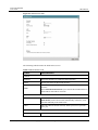
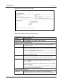
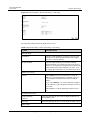
4.2.1 WAN Interface Edit
Use this screen to configure a WAN connection.
In the Network Setting > Broadband screen, click the Interface Setup section's Edit icon
next to the connection you want to configure, the screen displays as shown next.
Issue 01 (2014-01-15)
Copyright © Huawei Technologies Co., Ltd.
23
LTE TDD B2268H
User Guide
4 Broadband
Figure 4-3 WAN Interface Edit
The following table describes the fields in this screen.
Table 4-2 WAN Interface Edit
LABEL
DESCRIPTION
General
Enabled
Select the checkbox to enable the WAN interface.
Name
Specify the name for this WAN interface.
IPv4/IPv6
Select IPv4 Only if you just connect this WAN interface to an IPv4
network.
Mode
Select IPv6/IPv4 Dual Stack if you connect this WAN interface to
both an IPv6 and an IPv4 networks.
APN
Auto APN
Select this to have the LTE Device configure the APN (Access
Point Name) of an LTE network automatically. Otherwise, enter
the APN manually in the field below.
APN
Enter the APN of an LTE network, which your service provider
gave you.
MTU
MTU
Issue 01 (2014-01-15)
The Maximum Transmission Unit (MTU) defines the size of the
Copyright © Huawei Technologies Co., Ltd.
24
LTE TDD B2268H
User Guide
4 Broadband
LABEL
DESCRIPTION
largest packet allowed on an interface or connection. Enter the
MTU for this WAN interface in this field.
Routing Feature
NAT Enable
Select this option to activate NAT on this connection.
Apply as Default
Gateway
Select this option to have the LTE Device use the WAN interface of
this connection as the system default gateway.
IPv6 Address
Obtain IPv6 Address/
Prefix Automatically
Select this option to have the LTE Device use the IPv6 prefix from
the connected router's Router Advertisement (RA) to generate an
IPv6 address.
Enable
Non-temporary
Addresses
Select this option to have the LTE Device use the prefix to
automatically generate a unique IP address that does not need to be
maintained by a DHCP server.
Enable Prefix
Delegation
Select this option to use DHCP PD (Prefix Delegation) to allow the
LTE Device to pass the IPv6 prefix information to its LAN hosts.
The hosts can then use the prefix to generate their IPv6 addresses.
Static IPv6 Address
Select this option to configure a fixed IPv6 address for the Device's
LAN IPv6 address.
IPv6 Address
If you select static IPv6 address, enter the IPv6 address prefix that
the Device uses for the LAN IPv6 address.
Prefix length
If you select static IPv6 address, enter the IPv6 prefix length that the
Device uses to generate the LAN IPv6 address.
An IPv6 prefix length specifies how many most significant bits
(starting from the left) in the address compose the network address.
This field displays the bit number of the IPv6 subnet mask.
IPv6 Default Gateway
If you select static IPv6 address, enter the IPv6 default gateway's IP
or domain name address that helps forward traffic to other
networks.
IPv6 DNS Server
Obtain IPv6 DNS info
Automatically
Select this option to have the LTE Device get DNS information
from a DHCPv6 server.
Use the following
Static DNS IPv6
Address
Select this option if you have the IPv6 address of a DNS server and
then configure the DNS server's IPv6 address.
Primary IPv6 DNS
Server
Enter the primary DNS server's IPv6 address the LTE Device uses
and passes to the DHCPv6 clients.
Secondary IPv6 DNS
Server
Enter the secondary DNS server's IPv6 address the LTE Device
uses and passes to the DHCPv6 clients.
4 to 6 Tunnel
Enable DS-Lite 4to6
Issue 01 (2014-01-15)
Select this option to enable DS-Lite (Dual Stack Lite) to let local
Copyright © Huawei Technologies Co., Ltd.
25
LTE TDD B2268H
User Guide
4 Broadband
LABEL
DESCRIPTION
Endpoint IPv6
Address
computers use IPv4 through an ISP's IPv6 network.
Apply
Click Apply to save your changes.
Back
Click Back to return to the previous screen.
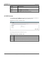
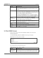
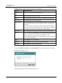
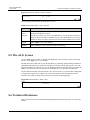
4.3 SIM Screen
If your LTE Device has the SIM screen, you may use it to specify the PIN for your SIM card.
Click Network Setting > Broadband > SIM to open the following screen.
Figure 4-4 Network Setting > Broadband > SIM
The following table describes the fields in this screen.
Table 4-3 Network Setting > Broadband > SIM
LABEL
DESCRIPTION
PIN
Enter the PIN from your LTE Internet service provider.
Apply
Click this to save the change in this section.
Cancel
Click this to restore your previously saved settings in this section.
Issue 01 (2014-01-15)
Copyright © Huawei Technologies Co., Ltd.
26
LTE TDD B2268H
User Guide
5 Wireless
5
Wireless
5.1 Overview
This chapter describes the LTE Device's Network Setting > Wireless screens. Use these
screens to set up your LTE Device's wireless connection.
5.1.1 Wireless Network Overview
Wireless networks consist of wireless clients, access points and bridges.
A wireless client is a radio connected to a user's computer.
An access point is a radio with a wired connection to a network, which can connect with
numerous wireless clients and let them access the network.
A bridge is a radio that relays communications between access points and wireless clients,
extending a network's range.
Traditionally, a wireless network operates in one of two ways.
An "infrastructure" type of network has one or more access points and one or more
wireless clients. The wireless clients connect to the access points.
An "ad-hoc" type of network is one in which there is no access point. Wireless clients
connect to one another in order to exchange information.
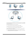
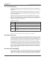
The following figure provides an example of a wireless network.
Issue 01 (2014-01-15)
Copyright © Huawei Technologies Co., Ltd.
27
LTE TDD B2268H
User Guide
5 Wireless
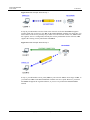
Figure 5-1 Example of a Wireless Network
The wireless network is the part in the blue circle. In this wireless network, devices A and B use
the access point (AP) to interact with the other devices (such as the printer) or with the Internet.
Your LTE Device is the AP.
Every wireless network must follow these basic guidelines.
Every device in the same wireless network must use the same SSID.
The SSID is the name of the wireless network. It stands for Service Set Identifier.
If two wireless networks overlap, they should use a different channel.
Like radio stations or television channels, each wireless network uses a specific channel, or
frequency, to send and receive information.
Every device in the same wireless network must use security compatible with the AP.
Security stops unauthorized devices from using the wireless network. It can also protect
the information that is sent in the wireless network.
Issue 01 (2014-01-15)
Copyright © Huawei Technologies Co., Ltd.
28
LTE TDD B2268H
User Guide
5 Wireless
Radio Channels
In the radio spectrum, there are certain frequency bands allocated for unlicensed, civilian use.
For the purposes of wireless networking, these bands are divided into numerous channels. This
allows a variety of networks to exist in the same place without interfering with one another.
When you create a network, you must select a channel to use.
Since the available unlicensed spectrum varies from one country to another, the number of
available channels also varies.
A channel is the radio frequencyused by wireless devices to transmit and receive data. Channels
available depend on your geographical area. You may have a choice of channels (for your
region) so you should use a channel different from an adjacent AP (access point) to reduce
interference. Interference occurs when radio signals from different access points overlap
causing interference and degrading performance.
Adjacent channels partially overlap however. To avoid interference due to overlap, your AP
should be on a channel at least five channels away from a channel that an adjacent AP is using.
For example, if your region has 11 channels and an adjacent AP is using channel 1, then you
need to select a channel between 6 or 11.
5.1.2 Before You Begin
Before you start using these screens, ask yourself the following questions. See Section 5.7if
some of the terms used here do not make sense to you.
What wireless standards do the other wireless devices support (IEEE 802.11g, for
example)? What is the most appropriate standard to use?
What security options do the other wireless devices support (WPA-PSK, for example)?
What is the best one to use?
Do the other wireless devices support WPS (Wi-Fi Protected Setup)? If so, you can set up
a well-secured network very easily.
Even if some of your devices support WPS and some do not, you can use WPS to set up your
network and then add the non-WPS devices manually, although this is somewhat more
complicated to do.
What advanced options do you want to configure, if any? If you want to configure
advanced options, ensure that you know precisely what you want to do. If you do not want
to configure advanced options, leave them alone.
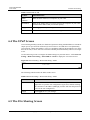
5.2 The Wireless General Screen
Use this screen to enable the Wireless LAN, enter the SSID and select the wireless security
mode.
If you are configuring the LTE Device from a computer connected to the wireless LAN and you change
the LTE Device's SSID or security settings, you will lose your wireless connection when you press
Apply to confirm. You must then change the wireless settings of your computer to match the LTE
Device's new settings.
Click Network Setting > Wireless to open the General screen. Select the Enable Wireless
LAN checkbox to show the Wireless configurations.
Issue 01 (2014-01-15)
Copyright © Huawei Technologies Co., Ltd.
29
LTE TDD B2268H
User Guide
5 Wireless
Figure 5-2 Network Setting >Wireless>General
The following table describes the labels in this screen.
Table 5-1 Network > Wireless LAN > General
LABEL
DESCRIPTION
Wireless Network Setup
Select the Enable Wireless LAN check box to activate the wireless
LAN.
Wireless
Wireless Network Settings
Wireless
Network Name
(SSID)
The SSID (Service Set IDentity) identifies the service set with which a
wireless device is associated. Wireless devices associating to the access
point (AP) must have the same SSID.
Enter a descriptive name (up to 32 English keyboard characters) for the
wireless LAN.
Hide SSID
Select this check box to hide the SSID in the outgoing beacon frame so a
station cannot obtain the SSID through scanning using a site survey tool.
BSSID
This shows the MAC address of the wireless interface on the LTE Device
when wireless LAN is enabled.
Mode Select
This makes sure that only compliant WLAN devices can associate with
the
LTE Device.
Select 802.11b/g/n to allow IEEE802.11b, IEEE802.11g and
IEEE802.11n compliant WLAN devices to associate with the LTE
Device. The transmission rate of your LTE Device might be reduced.
Select 802.11b/g to allow both IEEE802.11b and IEEE802.11g
compliant WLAN devices to associate with the LTE Device. The
transmission rate of your LTE Device might be reduced.
Select 802.11g Only to allow only IEEE 802.11g compliant WLAN
devices to associate with the LTE Device. Select 802.11n only in 2.4G
Issue 01 (2014-01-15)
Copyright © Huawei Technologies Co., Ltd.
30
LTE TDD B2268H
User Guide
5 Wireless
LABEL
DESCRIPTION
band to allow only IEEE 802.11n compliant WLAN devices with the
same frequency range (2.4 GHz) to associate with the LTE Device.
Channel
Selection
Set the channel depending on your particular region.
Operating
Channel
This is the channel currently being used by your AP.
Select a channel or use Auto to have the LTE Device automatically
determine a channel to use. If you are having problems with wireless
interference, changing the channel may help. Try to use a channel that is
as many channels away from any channels used by neighboring APs as
possible. The channel number which the LTE Device is currently using
then displays in the Operating Channel field.
Security Level
Security Mode
Select Basic or More Secure to add security on this wireless network.
The wireless clients which want to associate to this network must have
same wireless security settings as the LTE Device. When you select to
use a security, additional options appears in this screen.
Or you can select No Security to allow any client to associate this
network without any data encryption or authentication.
See the following sections for more details about wireless security modes.
Apply
Click Apply to save your changes back to the LTE Device.
Cancel
Click Cancel to restore your previously saved settings.
No Security
Select No Security to allow wireless stations to communicate with the access points without any data
encryption or authentication.
If you do not enable any wireless security on your LTE Device, your network is accessible to any
wireless networking device that is within range.
Figure 5-3 Wireless> General: No Security
The following table describes the labels in this screen.
Issue 01 (2014-01-15)
Copyright © Huawei Technologies Co., Ltd.
31
LTE TDD B2268H
User Guide
5 Wireless
Table 5-2 Wireless > General: No Security
LABEL
DESCRIPTION
Security Level
Choose No Security from the sliding bar.
5.2.1 Basic (Static WEP/Shared WEP Encryption)
WEP encryption scrambles the data transmitted between the wireless stations and the access
points (AP) to keep network communications private. Both the wireless stations and the access
points must use the same WEP key.
There are two types of WEP authentication namely, Open System (Static WEP) and Shared
Key (Shared WEP).
Open system is implemented for ease-of-use and when security is not an issue. The wireless
station and the AP or peer computer do not share a secret key. Thus the wireless stations can
associate with any AP or peer computer and listen to any transmitted data that is not encrypted.
Shared key mode involves a shared secret key to authenticate the wireless station to the AP or
peer computer. This requires you to enable the wireless LAN security and use same settings on
both the wireless station and the AP or peer computer.
In order to configure and enable WEP encryption, click Network Settings > Wireless to
display the General screen. Select Basic as the security level. Then select Static WEP or
Shared WEP from the Security Mode list.
Figure 5-4 Wireless>General: Basic(Static WEP/SharedWEP)
The following table describes the labels in this screen.
Issue 01 (2014-01-15)
Copyright © Huawei Technologies Co., Ltd.
32
LTE TDD B2268H
User Guide
5 Wireless
Table 5-3 Wireless > General: Basic (Static WEP/Shared WEP)
LABEL
DESCRIPTION
Security
Mode
Choose Static WEP or Shared WEP from the drop-down list box.
WEP Key
Select Static WEP to have the LTE Device allow association with
wireless clients that use Open System mode. Data transfer is encrypted
as long as the wireless client has the correct WEP key for encryption.
The LTE Device authenticates wireless clients using Shared Key mode
that have the correct WEP key
Select Shared WEP to have the LTE Device authenticate only those
wireless clients that use Shared Key mode and have the correct WEP
key.
Enter a WEP key that will be used to encrypt data. Both the LTE Device and
the wireless stations must use the same WEP key for data transmission.
5.2.2 More Secure (WPA(2)-PSK)
The WPA-PSK security mode provides both improved data encryption and user authentication
over WEP. Using a Pre-Shared Key (PSK), both the LTE Device and the connecting client share
a common password in order to validate the connection. This type of encryption, while robust,
is not as strong as WPA, WPA2 or even WPA2-PSK. The WPA2-PSK security mode is a newer,
more robust version of the WPA encryption standard. It offers slightly better security, although
the use of PSK makes it less robust than it could be.
Click Network Settings > Wireless to display the General screen. Select More Secure as the
security level. Then select WPA-PSK or WPA2-PSK from the Security Mode list.
Figure 5-5 Wireless > General: More Secure: WPA(2)-PSK
The following table describes the labels in this screen.
Issue 01 (2014-01-15)
Copyright © Huawei Technologies Co., Ltd.
33
LTE TDD B2268H
User Guide
5 Wireless
Table 5-4 Wireless > General: WPA(2)-PSK
LABEL
DESCRIPTION
Security Level
Select More Secure to enable WPA(2)-PSK data encryption.
Security Mode
Select WPA-PSK or WPA2-PSK from the drop-down list box.
Pre-Shared Key
The encryption mechanisms used for WPA/WPA2 and WPA-PSK/
WPA2-PSK are the same. The only difference between the two is that
WPA-PSK/WPA2-PSK uses a simple common password, instead of
user- specific credentials.
Type a pre-shared key from 8 to 63 case-sensitive ASCII characters or 64
hexadecimal digits.
more.../hide
more
Click more... to show more fields in this section. Click hide more to hide
them.
WPA-PSK
Compatible
This field appears when you choose WPA-PSK2 as the Security Mode.
Encryption
If the security mode is WPA-PSK, the encryption mode is set to TKIP to
enable Temporal Key Integrity Protocol (TKIP) security on your wireless
network.
Check this field to allow wireless devices using WPA-PSK security
mode to connect to your LTE Device. The LTE Device supports
WPA-PSK and WPA2-PSK simultaneously.
If the security mode is WPA-PSK2 and WPA-PSK Compatible is
disabled, the encryption mode is set to AES to enable Advanced
Encryption System (AES) security on your wireless network. AES
provides superior security to TKIP.
If the security mode is WPA-PSK2 and WPA-PSK Compatible is
enabled, the encryption mode is set to TKIPAES MIX to allow both
TKIP and AES types of security in your wireless network.
5.2.3 WPA(2) Authentication
The WPA2 security mode is currently the most robust form of encryption for wireless networks.
It requires a RADIUS server to authenticate user credentials and is a full implementation the
security protocol. Use this security option for maximum protection of your network. However,
it is the least backwards compatible with older devices.
The WPA security mode is a security subset of WPA2. It requires the presence of a RADIUS
server on your network in order to validate user credentials. This encryption standard is slightly
older than WPA2 and therefore is more compatible with older devices.
Click Network Settings > Wireless to display the General screen. Select More Secure as the
security level. Then select WPA or WPA2 from the Security Mode list.
Issue 01 (2014-01-15)
Copyright © Huawei Technologies Co., Ltd.
34
LTE TDD B2268H
User Guide
5 Wireless
Figure 5-6 Wireless > General: More Secure: WPA(2)
The following table describes the labels in this screen.
Table 5-5 Wireless > General: More Secure: WPA(2)
LABEL
DESCRIPTION
Security Level
Select More Secure to enable WPA(2)-PSK data encryption.
Security Mode
Choose WPA or WPA2 from the drop-down list box.
Authentication Server
IP Address
Enter the IP address of the external authentication server in dotted
decimal notation.
Port
Enter the port number of the external authentication server. The default
port number is 1812.
Number
You need not change this value unless your network administrator
instructs you to do so with additional information.
Shared
Secret
Enter a password (up to 128 alphanumeric characters) as the key to be
shared between the external authentication server and the LTE Device.
The key must be the same on the external authentication server and your
LTE Device. The key is not sent over the network.
more.../hide
more
Click more... to show more fields in this section. Click hide more to hide
them.
WPA
Compatible
This field is only available for WPA2. Select this if you want the LTE
Device to support WPA and WPA2 simultaneously.
Issue 01 (2014-01-15)
Copyright © Huawei Technologies Co., Ltd.
35
LTE TDD B2268H
User Guide
5 Wireless
LABEL
DESCRIPTION
Group Key
The Group Key Update Timer is the rate at which the RADIUS server
sends a new group key out to all clients.
Update Timer
If the value is set to "0", the update timer function is disabled.
Encryption
If the security mode is WPA, the encryption mode is set to TKIP to
enable Temporal Key Integrity Protocol (TKIP) security on your wireless
network.
If the security mode is WPA2, the encryption mode is set to AES to
enable Advanced Encryption System (AES) security on your wireless
network. AES provides superior security to TKIP.
5.3 The More AP Screen
The LTE Device can broadcast up to four wireless network names at the same time. This means
that users can connect to the LTE Device using different SSIDs. You can secure the connection
on each SSID profile so that wireless clients connecting to the LTE Device using different
SSIDs cannot communicate with each other.
This screen allows you to enable and configure multiple Basic Service Sets (BSSs) on the LTE
Device.
Click Network Settings > Wireless > More AP. The following screen displays.
Figure 5-7 Network Settings > Wireless > More AP
The following table describes the labels in this screen.
Table 5-6 Network Settings > Wireless > More AP
LABEL
DESCRIPTION
#
This is the index number of the entry.
Active
This field indicates whether this SSID is active. A yellow bulb signifies that
this SSID is active. A gray bulb signifies that this SSID is not active.
SSID
An SSID profile is the set of parameters relating to one of the LTE Device's
BSSs. The SSID (Service Set IDentifier) identifies the Service Set with which
a wireless device is associated.
This field displays the name of the wireless profile on the network. When a
wireless client scans for an AP to associate with, this is the name that is
Issue 01 (2014-01-15)
Copyright © Huawei Technologies Co., Ltd.
36
LTE TDD B2268H
User Guide
5 Wireless
LABEL
DESCRIPTION
broadcast and seen in the wireless client utility.
Security
This field indicates the security mode of the SSID profile.
Modify
Click the Edit icon to configure the SSID profile.
5.3.1 Edit More AP
Use this screen to edit an SSID profile. Click the Edit icon next to an SSID in the More AP
screen. The following screen displays.
Figure 5-8 Wireless>MoreAP:Edit
The following table describes the fields in this screen.
Table 5-7 Wireless > More AP: Edit
LABEL
DESCRIPTION
Wireless Network Setup
Select the Enable Wireless LAN check box to activate the wireless
LAN.
Wireless
Wireless Network Settings
Wireless
Network Name
(SSID)
The SSID (Service Set IDentity) identifies the service set with which a
wireless device is associated. Wireless devices associating to the access
point (AP) must have the same SSID.
Enter a descriptive name (up to 32 English keyboard characters) for the
wireless LAN.
Hide SSID
Issue 01 (2014-01-15)
Select this check box to hide the SSID in the outgoing beacon frame so a
station cannot obtain the SSID through scanning using a site survey tool.
Copyright © Huawei Technologies Co., Ltd.
37
LTE TDD B2268H
User Guide
5 Wireless
LABEL
DESCRIPTION
BSSID
This shows the MAC address of the wireless interface on the LTE
Device when wireless LAN is enabled.
Security Level
Security Mode
Select Basic (WEP) or More Secure (WPA(2)-PSK, WPA(2)) to add
security on this wireless network. The wireless clients which want to
associate to this network must have same wireless security settings as the
LTE Device. After you select to use a security, additional options
appears in this screen.
Or you can select No Security to allow any client to associate this
network without any data encryption or authentication.
See Section 5.2.1 for more details about this field.
Apply
Click Apply to save your changes.
Back
Click Back to exit this screen without saving.
5.4 The WPS Screen
Use this screen to configure WiFi Protected Setup (WPS) on your LTE Device.
WPS allows you to quickly set up a wireless network with strong security, without having to
configure security settings manually. Set up each WPS connection between two devices. Both
devices must support WPS. See 5.7.6 WiFi Protected Setup (WPS) for more information about
WPS.
The LTE Device applies the security settings of the SSID1 profile (see 5.2 The Wireless General
Screen ). If you want to use the WPS feature, make sure you have set the security mode of SSID1 to
WPA-PSK, WPA2-PSK or No Security.
Click Network Setting > Wireless > WPS. The following screen displays. Select Enable and
click Apply to activate the WPS function. Then you can configure the WPS settings in this
screen.
Issue 01 (2014-01-15)
Copyright © Huawei Technologies Co., Ltd.
38
LTE TDD B2268H
User Guide
5 Wireless
Figure 5-9 Network Setting >Wireless>WPS
The following table describes the labels in this screen.
Table 5-8 Network Setting > Wireless > WPS
LABEL
DESCRIPTION
Enable WPS
Select Enable to activate WPS on the LTE Device.
Add a new device with WPS Method
Method 1 PBC
Use this section to set up a WPS wireless network using Push Button
Configuration (PBC).
WPS
Click this button to add another WPS-enabled wireless device (within
wireless range of the LTE Device) to your wireless network. This button
may either be a physical button on the outside of device, or a menu button
similar to the WPS button on this screen.
Note: You must press the other wireless device's WPS button within two
minutes of pressing this button.
Method 2 PIN
Use this section to set up a WPS wireless network by entering the PIN
(Personal Identification Number) of the client into the LTE Device.
Register
Enter the PIN of the device that you are setting up a WPS connection with
and click Register to authenticate and add the wireless device to your
wireless network.
You can find the PIN either on the outside of the device, or by checking
the device's settings.
Note: You must also activate WPS on that device within two minutes to
have it present its PIN to the LTE Device.
WPS Configuration Summary
AP PIN
Issue 01 (2014-01-15)
The PIN of the LTE Device is shown here. Enter this PIN in the
configuration utility of the device you want to connect to using WPS.
Copyright © Huawei Technologies Co., Ltd.
39
LTE TDD B2268H
User Guide
5 Wireless
LABEL
DESCRIPTION
The PIN is not necessary when you use WPS push-button method.
Click the Generate New PIN button to have the LTE Device create a
new PIN.
Status
This displays Configured when the LTE Device has connected to a
wireless network using WPS or Enable WPS is selected and wireless or
wireless security settings have been changed. The current wireless and
wireless security settings also appear in the screen.
This displays Not Configured when there is no wireless or wireless
security changes on the LTE Device or you click Release Configuration
to remove the configured wireless and wireless security settings.
Release
Configuration
This button is available when the WPS status is Configured.
802.11 Mode
This is the 802.11 mode used. Only compliant WLAN devices can
associate with the LTE Device.
SSID
This is the name of the wireless network.
Security
This is the type of wireless security employed by the network.
Apply
Click Apply to save your changes.
Click this button to remove all configured wireless and wireless security
settings for WPS connections on the LTE Device.
5.5 The WMM Screen
Use this screen to enable or disable WiFi MultiMedia (WMM) wireless networks for
multimedia applications.
Click Network Setting > Wireless > WMM. The following screen displays.
Figure 5-10 Network Setting>Wireless>WMM
The following table describesthelabelsinthisscreen.
Table 5-9 Network Setting > Wireless > WMM
LABEL
DESCRIPTION
Enable WMM
This enables the LTE Device to automatically give a service a priority
level according to the ToS value in the IP header of packets it sends.
of SSID1~4
Issue 01 (2014-01-15)
Copyright © Huawei Technologies Co., Ltd.
40
LTE TDD B2268H
User Guide
5 Wireless
LABEL
DESCRIPTION
WMM QoS (WiFi MultiMedia Quality of Service) gives high priority to
voice and video, which makes them run more smoothly.
Enable WMM
Automatic
Power Save
Deliver (APSD)
Click this to increase battery life for battery-powered wireless clients.
APSD uses a longer beacon interval when transmitting traffic that does
not require a short packet exchange interval.
Apply
Click Apply to save your changes.
Cancel
Click Cancel to restore your previously saved settings.
5.6 Scheduling Screen
Click Network Setting > Wireless > Scheduling to open the Wireless LAN Scheduling
screen. Use this screen to configure when the LTE Device enables or disables the wireless LAN.
Figure 5-11 Network Setting > Wireless >Scheduling
The following table describes the labels in thisscreen.
Table 5-10 Network Setting > Wireless > Scheduling
LABEL
DESCRIPTION
Wireless LAN
Scheduling
Select Enable to activate wireless LAN scheduling on your LTE Device.
WLAN status
Select On or Off to enable or disable the wireless LAN.
Day
Select the day(s) you want to turn the wireless LAN on or off.
Between the
following times
Specify the time period during which to apply the schedule.
Issue 01 (2014-01-15)
For example, you want the wireless network to be only available during
work hours. Check Mon ~ Fri in the day column, and specify 8:00 ~
18:00 in the time table.
Copyright © Huawei Technologies Co., Ltd.
41
LTE TDD B2268H
User Guide
5 Wireless
LABEL
DESCRIPTION
Apply
Click Apply to save your changes.
Cancel
Click Cancel to restore your previously saved settings.
5.7 Technical Reference
This section discusses wireless LANs in depth.
5.7.1 Wireless Security Overview
By their nature, radio communications are simple to intercept. For wireless data networks, this
means that anyone within range of a wireless network without security can not only read the
data passing over the airwaves, but also join the network. Once an unauthorized person has
access to the network, he or she can steal information or introduce malware (malicious software)
intended to compromise the network. For these reasons, a variety of security systems have been
developed to ensure that only authorized people can use a wireless data network, or understand
the data carried on it.
These security standards do two things. First, they authenticate. This means that only people
presenting the right credentials (often a username and password, or a "key" phrase) can access
the network. Second, they encrypt. This means that the information sent over the air is encoded.
Only people with the code key can understand the information, and only people who have been
authenticated are given the code key.
These security standards vary in effectiveness. Some can be broken, such as the old Wired
Equivalent Protocol (WEP). Using WEP is better than using no security at all, but it will not
keep a determined attacker out. Other security standards are secure in themselves but can be
broken if a user does not use them properly. For example, the WPA-PSK security standard is
very secure if you use a long key which is difficult for an attacker's software to guess - for
example, a twenty-letter long string of apparently random numbers and letters - but it is not very
secure if you use a short key which is very easy to guess - for example, a three-letter word from
the dictionary.
Because of the damage that can be done by a malicious attacker, it's not just people who have
sensitive information on their network who should use security. Everybody who uses any
wireless network should ensure that effective security is in place.
A good way to come up with effective security keys, passwords and so on is to use obscure
information that you personally will easily remember, and to enter it in a way that appears
random and does not include real words. For example, if your mother owns a 1970 Dodge
Challenger and her favorite movie is Vanishing Point (which you know was made in 1971) you
could use "70dodchal71vanpoi" as your security key.
The following sections introduce different types of wireless security you can set up in the
wireless network.
Issue 01 (2014-01-15)
Copyright © Huawei Technologies Co., Ltd.
42
LTE TDD B2268H
User Guide
5 Wireless
5.7.2.1 SSID
Normally, the LTE Device acts like a beacon and regularly broadcasts the SSID in the area. You
can hide the SSID instead, in which case the LTE Device does not broadcast the SSID. In
addition, you should change the default SSID to something that is difficult to guess.
This type of security is fairly weak, however, because there are ways for unauthorized wireless
devices to get the SSID. In addition, unauthorized wireless devices can still see the information
that is sent in the wireless network.
5.7.2.2 MAC Address Filter
Every device that can use a wireless network has a unique identification number, called a MAC
address.1 A MAC address is usually written using twelve hexadecimal characters2; for example,
00A0C5000002 or 00:A0:C5:00:00:02. To get the MAC address for each device in the wireless
network, see the device's User's Guide or other documentation.
You can use the MAC address filter to tell the LTE Device which devices are allowed or not
allowed to use the wireless network. If a device is allowed to use the wireless network, it still
has to have the correct information (SSID, channel, and security). If a device is not allowed to
use the wireless network, it does not matter if it has the correct information.
This type of security does not protect the information that is sent in the wireless network.
Furthermore, there are ways for unauthorized wireless devices to get the MAC address of an
authorized device. Then, they can use that MAC address to use the wireless network.
1.
Some wireless devices, such as scanners, can detect wireless networks but cannot use
wireless networks. These kinds of wireless devices might not have MAC addresses.
2.
Hexadecimal characters are 0, 1, 2, 3, 4, 5, 6, 7, 8, 9, A, B, C, D, E, and F.
5.7.2.3 User Authentication
Authentication is the process of verifying whether a wireless device is allowed to use the
wireless network. You can make every user log in to the wireless network before using it.
However, every device in the wireless network has to support IEEE 802.1x to do this.
For wireless networks, you can store the user names and passwords for each user in a RADIUS
server. This is a server used in businesses more than in homes. If you do not have a RADIUS
server, you cannot set up user names and passwords for your users.
Unauthorized wireless devices can still see the information that is sent in the wireless network,
even if they cannot use the wireless network. Furthermore, there are ways for unauthorized
wireless users to get a valid user name and password. Then, they can use that user name and
password to use the wireless network.
5.7.2.4 Encryption
Wireless networks can use encryption to protect the information that is sent in the wireless
network. Encryption is like a secret code. If you do not know the secret code, you cannot
understand the message.
The types of encryption you can choose depend on the type of authentication. (See Section
5.7.2 for information about this.)
Issue 01 (2014-01-15)
Copyright © Huawei Technologies Co., Ltd.
43
LTE TDD B2268H
User Guide
5 Wireless
Figure 5-12 Types of Encryption for Each Type of Authentication
For example, if the wireless network has a RADIUS server, you can choose WPA or WPA2. If
users do not log in to the wireless network, you can choose no encryption, Static WEP,
WPA-PSK, or WPA2-PSK.
Usually, you should set up the strongest encryption that every device in the wireless network
supports. For example, suppose you have a wireless network with the LTE Device and you do
not have a RADIUS server. Therefore, there is no authentication. Suppose the wireless network
has two devices. Device A only supports WEP, and device B supports WEP and WPA.
Therefore, you should set up Static WEP in the wireless network.
It is recommended that wireless networks use WPA-PSK, WPA, or stronger encryption. The other types
of encryption are better than none at all, but it is still possible for unauthorized wireless devices to figure
out the original information pretty quickly.
When you select WPA2 or WPA2-PSK in your LTE Device, you can also select an option
(WPA compatible) to support WPA as well. In this case, if some of the devices support WPA
and some support WPA2, you should set up WPA2-PSK or WPA2 (depending on the type of
wireless network login) and select the WPA compatible option in the LTE Device.
Many types of encryption use a key to protect the information in the wireless network. The
longer the key, the stronger the encryption. Every device in the wireless network must have the
same key.
5.7.2 Signal Problems
Because wireless networks are radio networks, their signals are subject to limitations of
distance, interference and absorption.
Problems with distance occur when the two radios are too far apart. Problems with interference
occur when other radio waves interrupt the data signal. Interference may come from other radio
transmissions, such as military or air traffic control communications, or from machines that are
coincidental emitters such as electric motors or microwaves. Problems with absorption occur
when physical objects (such as thick walls) are between the two radios, muffling the signal.
5.7.3 BSS
A Basic Service Set (BSS) exists when all communications between wireless stations or
between a wireless station and a wired network client go through one access point (AP).
Intra-BSS traffic is traffic between wireless stations in the BSS. When Intra-BSS traffic
blocking is disabled, wireless station A and B can access the wired network and communicate
Issue 01 (2014-01-15)
Copyright © Huawei Technologies Co., Ltd.
44
LTE TDD B2268H
User Guide
5 Wireless
with each other. When Intra-BSS traffic blocking is enabled, wireless station A and B can still
access the wired network but cannot communicate with each other.
Figure 5-13 Basic Service set
5.7.4 MBSSID
Traditionally, you need to use different APs to configure different Basic Service Sets (BSSs).
As well as the cost of buying extra APs, there is also the possibility of channel interference. The
LTE Device's MBSSID (Multiple Basic Service Set IDentifier) function allows you to use one
access point to provide several BSSs simultaneously. You can then assign varying QoS
priorities and/or security modes to different SSIDs.
Wireless devices can use different BSSIDs to associate with the same AP.
5.7.5.1 Notes on Multiple BSSs
A maximum of eight BSSs are allowed on one AP simultaneously.
You must use different keys for different BSSs. If two wireless devices have different
BSSIDs (they are in different BSSs), but have the same keys, they may hear each other's
communications (but not communicate with each other).
MBSSID should not replace but rather be used in conjunction with 802.1x security.
5.7.5 WiFi Protected Setup (WPS)
Your LTE Device supports WiFi Protected Setup (WPS), which is an easy way to set up a secure
wireless network. WPS is an industry standard specification, defined by the WiFi Alliance.
WPS allows you to quickly set up a wireless network with strong security, without having to
configure security settings manually. Each WPS connection works between two devices. Both
devices must support WPS (check each device's documentation to make sure).
Depending on the devices you have, you can either press a button (on the device itself, or in its
configuration utility) or enter a PIN (a unique Personal Identification Number that allows one
Issue 01 (2014-01-15)
Copyright © Huawei Technologies Co., Ltd.
45
LTE TDD B2268H
User Guide
5 Wireless
device to authenticate the other) in each of the two devices. When WPS is activated on a device,
it has two minutes to find another device that also has WPS activated. Then, the two devices
connect and set up a secure network by themselves.
5.7.5.1 Push Button Configuration
WPS Push Button Configuration (PBC) is initiated by pressing a button on each WPS-enabled
device, and allowing them to connect automatically. You do not need to enter any information.
Not every WPS-enabled device has a physical WPS button. Some may have a WPS PBC button
in their configuration utilities instead of or in addition to the physical button. Take the following
steps to set up WPS using the button.
Step 1 Ensure that the two devices you want to set up are within wireless range of one
another.
Step 2 Look for a WPS button on each device. If the device does not have one, log into its
configuration utility and locate the button (see the device's User's Guide for how to do this - for
the LTE Device, see Section 5.4).
Step 3 Press the button on one of the devices (it doesn't matter which). For the LTE Device
you must press the WPS button for more than three seconds.
Step 4 Within two minutes, press the button on the other device. The registrar sends the
network name (SSID) and security key through a secure connection to the enrollee.
If you need to make sure that WPS worked, check the list of associated wireless clients in the
AP's configuration utility. If you see the wireless client in the list, WPS was successful.
5.7.5.2 PIN Configuration
Each WPS-enabled device has its own PIN (Personal Identification Number). This may either
be static (it cannot be changed) or dynamic (in some devices you can generate a new PIN by
clicking on a button in the configuration interface).
Use the PIN method instead of the push-button configuration (PBC) method if you want to
ensure that the connection is established between the devices you specify, not just the first two
devices to activate WPS in range of each other. However, you need to log into the configuration
interfaces of both devices to use the PIN method.
When you use the PIN method, you must enter the PIN from one device (usually the wireless
client) into the second device (usually the Access Point or wireless router). Then, when WPS is
activated on the first device, it presents its PIN to the second device. If the PIN matches, one
device sends the network and security information to the other, allowing it to join the network.
Take the following steps to set up a WPS connection between an access point or wireless router
(referred to here as the AP) and a client device using the PIN method.
Step 1 Ensure WPS is enabled on both devices.
Step 2 Access the WPS section of the AP's configuration interface. See the device's User's Guide for
how to do this.
Step 3 Look for the client's WPS PIN; it will be displayed either on the device, or in the WPS section
of the client's configuration interface (see the device's User's Guide for how to find the WPS
PIN - for the LTE Device, see Section 5.4 ).
Step 4 Enter the client's PIN in the AP's configuration interface.
Issue 01 (2014-01-15)
Copyright © Huawei Technologies Co., Ltd.
46
LTE TDD B2268H
User Guide
5 Wireless
Step 5 If the client device's configuration interface has an area for entering another device's PIN, you
can either enter the client's PIN in the AP, or enter the AP's PIN in the client - it does not matter
which.
Step 6 Start WPS on both devices within two minutes.
Step 7 Use the configuration utility to activate WPS, not the push-button on the device itself.
Step 8 On a computer connected to the wireless client, try to connect to the Internet. If you can connect,
WPS was successful.
----End
If you cannot connect, check the list of associated wireless clients in the AP's configuration
utility. If you see the wireless client in the list, WPS was successful.
The following figure shows a WPS-enabled wireless client (installed in a notebook computer)
connecting to the WPS-enabled AP via the PIN method.
Issue 01 (2014-01-15)
Copyright © Huawei Technologies Co., Ltd.
47
LTE TDD B2268H
User Guide
5 Wireless
Figure 5-14 Example WPS Process: PIN Method
5.7.5.3 How WPS Works
When two WPS-enabled devices connect, each device must assume a specific role. One device
acts as the registrar (the device that supplies network and security settings) and the other device
acts as the enrollee (the device that receives network and security settings. The registrar creates
a secure EAP (Extensible Authentication Protocol) tunnel and sends the network name (SSID)
and the WPA-PSK or WPA2-PSK pre-shared key to the enrollee. Whether WPA-PSK or
WPA2-PSK is used depends on the standards supported by the devices. If the registrar is
already part of a network, it sends the existing information. If not, it generates the SSID and
WPA(2)-PSK randomly.
The following figure shows a WPS-enabled client (installed in a notebook computer)
connecting to a WPS-enabled access point.
Issue 01 (2014-01-15)
Copyright © Huawei Technologies Co., Ltd.
48
LTE TDD B2268H
User Guide
5 Wireless
Figure 5-15 Example WPS Process: PIN Method
The roles of registrar and enrollee last only as long as the WPS setup process is active (two
minutes). The next time you use WPS, a different device can be the registrar if necessary.
The WPS connection process is like a handshake; only two devices participate in each WPS
transaction. If you want to add more devices you should repeat the process with one of the
existing networked devices and the new device.
Note that the access point (AP) is not always the registrar, and the wireless client is not always
the enrollee. All WPS-certified APs can be a registrar, and so can some WPS-enabled wireless
clients.
By default, a WPS device is "unconfigured". This means that it is not part of an existing
network and can act as either enrollee or registrar (if it supports both functions). If the registrar
is unconfigured, the security settings it transmits to the enrollee are randomly- generated. Once
a WPS-enabled device has connected to another device using WPS, it becomes "configured". A
configured wireless client can still act as enrollee or registrar in subsequent WPS connections,
but a configured access point can no longer act as enrollee. It will be the registrar in all
subsequent WPS connections in which it is involved. If you want a configured AP to act as an
enrollee, you must reset it to its factory defaults.
5.7.5.4 Example WPS Network Setup
This section shows how security settings are distributed in an example WPS setup.
The following figure shows an example network. In step 1, both AP1 and Client 1 are
unconfigured. When WPS is activated on both, they perform the handshake. In this example,
AP1 is the registrar, and Client 1 is the enrollee. The registrar randomly generates the security
information to set up the network, since it is unconfigured and has no existing information.
Issue 01 (2014-01-15)
Copyright © Huawei Technologies Co., Ltd.
49
LTE TDD B2268H
User Guide
5 Wireless
Figure 5-16 WPS: Example Network Step 1
In step 2, you add another wireless client to the network. You know that Client 1 supports
registrar mode, but it is better to use AP1 for the WPS handshake with the new client since you
must connect to the access point anyway in order to use the network. In this case, AP1 must be
the registrar, since it is configured (it already has security information for the network). AP1
supplies the existing security information to Client 2.
Figure 5-17 WPS: Example Network Step 2
In step 3, you add another access point (AP2) to your network. AP2 is out of range of AP1, so
you cannot use AP1 for the WPS handshake with the new access point. However, you know
that Client 2 supports the registrar function, so you use it to perform the WPS handshake
instead.
Issue 01 (2014-01-15)
Copyright © Huawei Technologies Co., Ltd.
50
LTE TDD B2268H
User Guide
5 Wireless
Figure 5-18 WPS: Example Network Step 3
5.7.5.5 Limitations of WPS
WPS has some limitations of which you should be aware.
WPS works in Infrastructure networks only (where an AP and a wireless client
communicate). It does not work in Ad-Hoc networks (where there is no AP).
When you use WPS, it works between two devices only. You cannot enroll multiple
devices simultaneously; you must enroll one after the other.
For instance, if you have two enrollees and one registrar you must set up the first enrollee (by
pressing the WPS button on the registrar and the first enrollee, for example), then check that it
successfully enrolled, then set up the second device in the same way.
WPS works only with other WPS-enabled devices. However, you can still add non-WPS
devices to a network you already set up using WPS.
WPS works by automatically issuing a randomly-generated WPA-PSK or WPA2-PSK preshared key from the registrar device to the enrollee devices. Whether the network uses
WPA-PSK or WPA2-PSK depends on the device. You can check the configuration interface of
the registrar device to discover the key the network is using (if the device supports this feature).
Then, you can enter the key into the non-WPS device and join the network as normal (the
non-WPS device must also support WPA-PSK or WPA2-PSK).
When you use the PBC method, there is a short period (from the moment you press the
button on one device to the moment you press the button on the other device) when any
WPS-enabled device could join the network. This is because the registrar has no way of
identifying the "correct" enrollee, and cannot differentiate between your enrollee and a
rogue device. This is a possible way for a hacker to gain access to a network.
You can easily check to see if this has happened. WPS works between only two devices
simultaneously, so if another device has enrolled your device will be unable to enroll, and will
not have access to the network. If this happens, open the access point's configuration interface
Issue 01 (2014-01-15)
Copyright © Huawei Technologies Co., Ltd.
51
LTE TDD B2268H
User Guide
5 Wireless
and look at the list of associated clients (usually displayed by MAC address). It does not matter
if the access point is the WPS registrar, the enrollee, or was not involved in the WPS handshake;
a rogue device must still associate with the access point to gain access to the network. Check the
MAC addresses of your wireless clients (usually printed on a label on the bottom of the device).
If there is an unknown MAC address you can remove it or reset the AP.
Issue 01 (2014-01-15)
Copyright © Huawei Technologies Co., Ltd.
52
LTE TDD B2268H
User Guide
6 Home Networking
6
Home Networking
6.1 Overview
A Local Area Network (LAN) is a shared communication system to which many computers are
attached. A LAN is usually located in one immediate area such as a building or floor of a
building.
The LAN screens can help you configure a LAN DHCP server and manage IP addresses.
6.1.1 What You Need To Know
The following terms and concepts may help as you read this chapter.
6.1.1.1 About LAN IP Address
Similar to the way houses on a street share a common street name, so too do computers on a
LAN share one common network number. This is known as an Internet Protocol address.
Subnet Mask
The subnet mask specifies the network number portion of an IP address. Your LTE Device will
compute the subnet mask automatically based on the IP address that you entered. You don't
need to change the subnet mask computed by the LTE Device unless you are instructed to do
otherwise.
Issue 01 (2014-01-15)
Copyright © Huawei Technologies Co., Ltd.
53
LTE TDD B2268H
User Guide
6 Home Networking
DHCP
DHCP (Dynamic Host Configuration Protocol) allows clients to obtain TCP/IP configuration at
start-up from a server. This LTE Device has a built-in DHCP server capability that assigns IP
addresses and DNS servers to systems that support DHCP client capability.
DNS
DNS (Domain Name System) maps a domain name to its corresponding IP address and vice
versa. The DNS server is extremely important because without it, you must know the IP address
of a computer before you can access it. The DNS server addresses you enter when you set up
DHCP are passed to the client machines along with the assigned IP address and subnet mask.
6.1.1.2 About UPnP
How do I know if I'm using UPnP?
UPnP hardware is identified as an icon in the Network Connections folder (Windows XP). Each
UPnP compatible device installed on your network will appear as a separate icon. Selecting the
icon of a UPnP device will allow you to access the information and properties of that device.
Cautions with UPnP
The automated nature of NAT traversal applications in establishing their own services and
opening firewall ports may present network security issues. Network information and
configuration may also be obtained and modified by users in some network environments.
When a UPnP device joins a network, it announces its presence with a multicast message. For
security reasons, the LTE Device allows multicast messages on the LAN only.
All UPnP-enabled devices may communicate freely with each other without additional
configuration. Disable UPnP if this is not your intention.
6.2 The LAN Setup Screen
Click Network Setting > Home Networking to open the LAN Setup screen. Use this screen to
set the Local Area Network IP address and subnet mask of your LTE Device and configure the
DNS server information that the LTE Device sends to the DHCP client devices on the LAN.
Issue 01 (2014-01-15)
Copyright © Huawei Technologies Co., Ltd.
54
LTE TDD B2268H
User Guide
6 Home Networking
Figure 6-1 Network Setting > Home Networking > LAN Setup
The following table describes the fields in this screen.
Table 6-1 Network Setting > Home Networking > LAN Setup
LABEL
DESCRIPTION
LAN IP Setup
IP Address
Enter the LAN IP address you want to assign to your
LTE Device in dotted decimal notation, for example,
192.168.1.1 (factory default).
IP Subnet Mask
Type the subnet mask of your network in dotted
decimal notation, for example 255.255.255.0 (factory
default). Your LTE Device automatically computes the
subnet mask based on the IP address you enter, so do
not change this field unless you are instructed to do so.
DHCP Server State
Select Enable to have your LTE Device assign IP
addresses, an IP default gateway and DNS servers to
LAN computers and other devices that are DHCP
clients.
DHCP
If you select Disable, you need to manually configure
the IP addresses of the computers and other devices on
your LAN.
When DHCP is used, the following fields need to be
set.
IP Addressing Values
Address
This field specifies the first of the contiguous addresses in
the IP address pool.
Pool Size
This field specifies the size, or count of the IP address pool.
IP Pool Starting
DNS Values
Issue 01 (2014-01-15)
Copyright © Huawei Technologies Co., Ltd.
55
LTE TDD B2268H
User Guide
6 Home Networking
LABEL
DESCRIPTION
DNS Server 1-3
Select From ISP if your ISP dynamically assigns DNS
server information (and the LTE Device's WAN IP address).
Select DNS-Proxy to have the LTE Device send its own
address to the LAN clients for them to use as the DNS server.
Select User-Defined if you have the IP address of a DNS
server. Enter the DNS server's IP address in the field to the
right. If you chose User- Defined, but leave the IP address
set to 0.0.0.0, User-Defined changes to None after you click
Apply. If you set a second choice to User-Defined, and enter
the same IP address, the second User-Defined changes to
None after you click Apply.
Select None if you do not want to configure DNS servers.
You must have another DHCP sever on your LAN, or else
the computers must have their DNS server addresses
manually configured. If you do not configure a DNS server,
you must know the IP address of a computer in order to
access it.
Apply
Click Apply to save your changes.
Cancel
Click Cancel to restore your previously saved settings.
6.3 The Static DHCP Screen
This table allows you to assign IP addresses on the LAN to specific individual computers based
on their MAC Addresses.
Every Ethernet device has a unique MAC (Media Access Control) address. The MAC address
is assigned at the factory and consists of six pairs of hexadecimal characters, for example,
00:A0:C5:00:00:02.
6.3.1 Before You Begin
Find out the MAC addresses of your network devices if you intend to add them to the Static
DHCP screen.
Use this screen to change your LTE Device's static DHCP settings. Click Network Setting >
Home Networking > Static DHCP to open the following screen.
Figure 6-2 Network Setting > Home Networking > Static DHCP
The following table describes the labels in this screen.
Issue 01 (2014-01-15)
Copyright © Huawei Technologies Co., Ltd.
56
LTE TDD B2268H
User Guide
6 Home Networking
Table 6-2 Network Setting > Home Networking > Static DHCP
LABEL
DESCRIPTION
Add new static
lease
Click this to add a new static DHCP entry.
#
This is the index number of the entry.
Status
This field displays whether the client is connected to the LTE Device.
Host Name
This field displays the client host name.
MAC Address
The MAC (Media Access Control) or Ethernet address on a LAN (Local
Area Network) is unique to your computer (six pairs of hexadecimal
notation).
A network interface card such as an Ethernet adapter has a hardwired
address that is assigned at the factory. This address follows an industry
standard that ensures no other adapter has a similar address.
IP Address
This field displays the IP address relative to the # field listed above.
Reserve
Select the check box in the heading row to automatically select all check
boxes or select the check box(es) in each entry to have the LTE Device
always assign the selected entry(ies)'s IP address(es) to the
corresponding MAC address(es) (and host name(s)). You can select up
to 128 entries in this table.
Apply
Click Apply to save your changes.
Cancel
Click Cancel to restore your previously saved settings.
Refresh
Click Refresh to reload the DHCP table.
If you click Add new static lease in the Static DHCP screen, the following screen displays.
Figure 6-3 Static DHCP: Add
The following table describes the labels in this screen.
Issue 01 (2014-01-15)
Copyright © Huawei Technologies Co., Ltd.
57
LTE TDD B2268H
User Guide
6 Home Networking
Table 6-3 Static DHCP: Add
LABEL
DESCRIPTION
MAC
Address
Enter the MAC address of a computer on your LAN.
IP Address
Enter the IP address that you want to assign to the computer on your LAN
with the MAC address that you will also specify.
Apply
Click Apply to save your changes.
Back
Click Back to exit this screen without saving.
6.4 The UPnP Screen
Universal Plug and Play (UPnP) is a distributed, open networking standard that uses TCP/IP for
simple peer-to-peer network connectivity between devices. A UPnP device can dynamically
join a network, obtain an IP address, convey its capabilities and learn about other devices on the
network. In turn, a device can leave a network smoothly and automatically when it is no longer
in use.
Use the following screen to configure the UPnP settings on your LTE Device. Click Network
Setting > Home Networking > Static DHCP > UPnP to display the screen shown next.
Figure 6-4 Network Setting > Home Networking > UPnP
The following table describes the labels in this screen.
Table 6-4 Network Settings > Home Networking > UPnP
LABEL
DESCRIPTION
UPnP
Select Enable to activate UPnP. Be aware that anyone could use a UPnP
application to open the web configurator's login screen without entering
the LTE Device's IP address (although you must still enter the password
to access the web configurator).
Apply
Click Apply to save your changes.
6.5 The File Sharing Screen
Issue 01 (2014-01-15)
Copyright © Huawei Technologies Co., Ltd.
58
LTE TDD B2268H
User Guide
6 Home Networking
CPE Only support FAT32 and maximun disk size 1TB for USB memory stick or hard drive
You can share files on a USB memory stick or hard drive connected to your LTE Device with
users on your network. Use this screen to set up file sharing using the LTE Device.
To access this screen, click Network Setting > Home Networking > File Sharing.
Figure 6-5 Network Setting > Home Networking > File Sharing
Each field is described in the following table.
Table 6-5 Network Settings > Home Networking > File Sharing
LABEL
DESCRIPTION
File Sharing
Services (SMB)
Select Enable and click Apply to activate file sharing through the LTE
Host Name
The name of the LTE Device.
Workgroup
Name
Type your workgroup name in this field. A workgroup is a group of
computers on a network that can share files.
Apply
Click Apply to save your changes.
Cancel
Click Cancel to restore your previously saved settings.
Device.
Click Computer->Network on your PC and click ROUTER which is your USB.
Issue 01 (2014-01-15)
Copyright © Huawei Technologies Co., Ltd.
59
LTE TDD B2268H
User Guide
6 Home Networking
6.6 The Media Server Screen
The media server feature lets anyone on your network play video, music, and photos from the
USB storage device connected to your LTE Device (without having to copy them to another
computer). The LTE Device can function as a DLNA-compliant media server. The LTE Device
streams files to DLNA-compliant media clients (like Windows Media Player). The Digital
Living Network Alliance (DLNA) is a group of personal computer and electronics companies
that works to make products compatible in a home network.
The LTE Device media server enables you to:
• Publish all shares for everyone to play media files in the USB storage device connected to the
LTE Device.
• Use hardware-based media clients to play the files.
Anyone on your network can play the media files in the published shares. No username and password or
other form of security is used. The media server is enabled by default with the video, photo, and music
shares published.
To change your LTE Device's media server settings, click Network Setting > Home
Networking > Media Server. The screen appears as shown.
Issue 01 (2014-01-15)
Copyright © Huawei Technologies Co., Ltd.
60
LTE TDD B2268H
User Guide
6 Home Networking
Figure 6-6 Network Setting > Home Networking > Media Server
Each field is described in the following table.
Table 6-6 Network Settings > Home Networking > Media Server
LABEL
DESCRIPTION
Enable Media
Server
Select Enable to have the LTE Device function as a DLNA-compliant
media server.
Enable the media server to let (DLNA-compliant) media clients on your
network play media
files located in the shares.
Apply
Click Apply to save your changes.
Click Computer->Network on your PC and click B2268H under Media Devices.
Here is your Media files from your USB
Issue 01 (2014-01-15)
Copyright © Huawei Technologies Co., Ltd.
61
LTE TDD B2268H
User Guide
Issue 01 (2014-01-15)
6 Home Networking
Copyright © Huawei Technologies Co., Ltd.
62
LTE TDD B2268H
User Guide
7 Routing
7
Routing
7.1 Overview
The LTE Device usually uses the default gateway to route outbound traffic from computers on
the LAN to the Internet. To have the LTE Device send data to devices not reachable through the
default gateway, use static routes.
For example, the next figure shows a computer (A) connected to the LTE Device's LAN
interface. The LTE Device routes most traffic from A to the Internet through the LTE Device's
default gateway (R1). You create one static route to connect to services offered by your ISP
behind router R2. You create another static route to communicate with a separate network
behind a router R3 connected to the LAN.
Figure 7-1 Example of Static Routing Topology
7.2 Configuring Static Route
Use this screen to view and configure IPv4 static routes on the LTE Device. Click Network
Setting > Static Route to open the following screen.
Issue 01 (2014-01-15)
Copyright © Huawei Technologies Co., Ltd.
63
LTE TDD B2268H
User Guide
7 Routing
Figure 7-2 Network Setting >StaticRoute
The following table describes the labels in this screen.
Table 7-1 Network Setting > Static Route
LABEL
DESCRIPTION
Add New
Click this to set up a new IPv4 static route on the LTE Device.
Static Route
#
This is the number of an individual static route.
Active
This indicates whether the route is active or not.
A yellow bulb signifies that this static route is active. A gray bulb
signifies that this static route is not active.
Status
This shows whether the static route is currently in use or not. A yellow
bulb signifies that this static route is in use. A gray bulb signifies that this
static route is not in use.
Name
This is the name that describes or identifies this route.
Destination IP
This parameter specifies the IPv4 IP network address of the final
destination. Routing is always based on network number.
Gateway
This is the IPv4 IP address of the gateway. The gateway is a router or
switch on the same network segment as the device's LAN or WAN port.
The gateway helps forward packets to their destinations.
Subnet Mask
This parameter specifies the IP network subnet mask of the final
destination.
Interface
This indicates which interface handles the traffic forwarded by this
route.
Modify
Click the Edit icon to go to the screen where you can set up a static route
on the LTE Device.
Click the Delete icon to remove a static route from the LTE Device.
7.2.1 Add/Edit Static Route
Click add new Static Route in the Routing screen or click the Edit icon next to a rule. The
following screen appears. Use this screen to configure the required information for a static
route.
Issue 01 (2014-01-15)
Copyright © Huawei Technologies Co., Ltd.
64
LTE TDD B2268H
User Guide
7 Routing
Figure 7-3 Routing: Add/Edit
The following table describes the labels in this screen.
Table 7-2 Routing: Add/Edit
LABEL
DESCRIPTION
Active
Click this to activate this static route.
Route Name
Enter the name of the IP static route. Leave this field blank to delete this
static route.
Destination IP
Address
This parameter specifies the IP network address of the final destination.
Routing is always based on network number. If you need to specify a
route to a single host, use a subnet mask of 255.255.255.255 in the
subnet mask field to force the network number to be identical to the host
ID.
IP Subnet Mask
Enter the IP subnet mask here.
Gateway IP
Address
You can decide if you want to forward packets to a gateway IP address
or a bound interface.
If you want to configure Gateway IP Address, enter the IP address of
the next-hop gateway. The gateway is a router or switch on the same
network segment as the device's LAN or WAN port. The gateway helps
forward packets to their destinations.
Bound
Interface
You can decide if you want to forward packets to a gateway IP address
or a bound interface.
If you want to configure Bound Interface, select the check box and
choose an interface through which the traffic is sent.
Apply
Click Apply to save your changes.
Back
Click Back to exit this screen without saving.
Issue 01 (2014-01-15)
Copyright © Huawei Technologies Co., Ltd.
65
LTE TDD B2268H
User Guide
8 Network Address Translation (NAT)
8
Network Address Translation (NAT)
8.1 Overview
NAT (Network Address Translation - NAT, RFC 1631) is the translation of the IP address of a
host in a packet, for example, the source address of an outgoing packet, used within one
network to a different IP address known within another network.
8.1.1 What You Need To Know
The following terms and concepts may help as you read this chapter.
Inside/Outside and Global/Local
Inside/outside denotes where a host is located relative to the LTE Device, for example, the
computers of your subscribers are the inside hosts, while the web servers on the Internet are the
outside hosts.
Global/local denotes the IP address of a host in a packet as the packet traverses a router, for
example, the local address refers to the IP address of a host when the packet is in the local
network, while the global address refers to the IP address of the host when the same packet is
traveling in the WAN side.
NAT
In the simplest form, NAT changes the source IP address in a packet received from a subscriber
(the inside local address) to another (the inside global address) before forwarding the packet to
the WAN side. When the response comes back, NAT translates the destination address (the
inside global address) back to the inside local address before forwarding it to the original inside
host.
Port Forwarding
A port forwarding set is a list of inside (behind NAT on the LAN) servers, for example, web or
FTP, that you can make visible to the outside world even though NAT makes your whole inside
network appear as a single computer to the outside world.
Finding Out More
See Section 9.5 for advanced technical information on NAT.
Issue 01 (2014-01-15)
Copyright © Huawei Technologies Co., Ltd.
66
LTE TDD B2268H
User Guide
8 Network Address Translation (NAT)
8.2 The Port Forwarding Screen
Use the Port Forwarding screen to forward incoming service requests to the server(s) on your
local network.
You may enter a single port number or a range of port numbers to be forwarded, and the local IP
address of the desired server. The port number identifies a service; for example, web service is
on port 80 and FTP on port 21. In some cases, such as for unknown services or where one server
can support more than one service (for example both FTP and web service), it might be better to
specify a range of port numbers. You can allocate a server IP address that corresponds to a port
or a range of ports.
Please refer to RFC 1700 for further information about port numbers.
Many residential broadband ISP accounts do not allow you to run any server processes (such as a Web or
FTP server) from your location. Your ISP may periodically check for servers and may suspend your
account if it discovers any active services at your location. If you are unsure, refer to your ISP.
Configuring Servers Behind Port Forwarding (Example)
Let's say you want to assign ports 21-25 to one FTP, Telnet and SMTP server (A in the example),
port 80 to another (B in the example) and assign a default server IP address of 10.0.0.35 to a
third (C in the example). You assign the LAN IP addresses and the ISP assigns the WAN IP
address. The NAT network appears as a single host on the Internet.
Figure 8-1 Multiple Servers Behind NAT Example
8.2.1 The Port Forwarding Screen
Click Network Setting > NAT to open the Port Forwarding screen.
Figure 8-2 Network Setting >NAT >Port Forwarding
The following table describes the fields in this screen.
Issue 01 (2014-01-15)
Copyright © Huawei Technologies Co., Ltd.
67
LTE TDD B2268H
User Guide
8 Network Address Translation (NAT)
Table 8-1 Network Setting > NAT > Port Forwarding
LABEL
DESCRIPTION
Add new rule
Click this to add a new port forwarding rule.
#
This is the index number of the entry.
Status
This field indicates whether the rule is active or not.
A yellow bulb signifies that this rule is active. A gray bulb signifies that
this rule is not active.
Service Name
This is the service's name. This shows User Defined if you manually
added a service. You can change this by clicking the edit icon.
WAN Interface
This shows the WAN interface through which the service is forwarded.
Start Port
This is the first external port number that identifies a service.
End Port
This is the last external port number that identifies a service.
Translation Start
Port
This is the first internal port number that identifies a service.
Translation End
Port
This is the last internal port number that identifies a service.
Server IP Address
This is the server's IP address.
Protocol
This shows the IP protocol supported by this virtual server, whether it
is TCP, UDP, or TCP/UDP.
Modify
Click the Edit icon to edit the port forwarding rule.
Click the Delete icon to delete an existing port forwarding rule. Note
that subsequent address mapping rules move up by one when you take
this action.
Apply
Click Apply to save your changes.
Cancel
Click Cancel to restore your previously saved settings.
8.2.2 The Port Forwarding Edit Screen
This screen lets you create or edit a port forwarding rule. Click Add new rule in the Port
Forwarding screen or the Edit icon next to an existing rule to open the following screen.
Issue 01 (2014-01-15)
Copyright © Huawei Technologies Co., Ltd.
68
LTE TDD B2268H
User Guide
8 Network Address Translation (NAT)
Figure 8-3 Port Forwarding: Add/Edit
The following table describes the labels in this screen.
Table 8-2 Port Forwarding: Add/Edit
LABEL
DESCRIPTION
Service Name
Enter a name to identify this rule using keyboard characters (A-Z, a-z,
1-2 and so on).
WAN Interface
This is the WAN interface through which the service is forwarded.
Start Port
Enter the original destination port for the packets.
To forward only one port, enter the port number again in the External
End Port field.
To forward a series of ports, enter the start port number here and the end
port number in the External End Port field.
End Port
Enter the last port of the original destination port range.
To forward only one port, enter the port number in the External Start
Port field above and then enter it again in this field.
To forward a series of ports, enter the last port number in a series that
begins with the port number in the External Start Port field above.
Translation Start
Port
This shows the port number to which you want the LTE Device to
translate the incoming port. For a range of ports, enter the first number
of the range to which you want the incoming ports translated.
Translation End
Port
This shows the last port of the translated port range.
Server IP Address
Enter the inside IP address of the virtual server here.
Issue 01 (2014-01-15)
Copyright © Huawei Technologies Co., Ltd.
69
LTE TDD B2268H
User Guide
8 Network Address Translation (NAT)
LABEL
DESCRIPTION
Protocol
Select the protocol supported by this virtual server. Choices are TCP,
UDP, or TCP/UDP.
Apply
Click Apply to save your changes.
Back
Click Back to return to the previous screen without saving.
8.3 The DMZ Screen
Use this page to set the IP address of your network DMZ (if you have one) for the LTE Device.
All incoming packets received by this LTE Device's WAN interface will be forwarded to the
default server you set.
Click Network Setting > NAT > DMZ to display the following screen.
The configuration you set in this screen takes priority than the Network Setting > NAT > Port
Forwarding screen.
Figure 8-4 Network Setting > NAT > DMZ
The following table describes the fields in this screen.
Table 8-3 Network Setting > NAT > DMZ
LABEL
DESCRIPTION
Default Server
Address
Enter the IP address of your network DMZ host, if you have one. 0.0.0.0
means this feature is disabled.
Apply
Click Apply to save your changes.
Cancel
Click Cancel to restore your previously saved settings.
8.4 The Sessions Screen
Use the Sessions screen to limit the number of concurrent NAT sessions each client can use.
Click Network Setting > NAT > Sessions to display the following screen.
Issue 01 (2014-01-15)
Copyright © Huawei Technologies Co., Ltd.
70
LTE TDD B2268H
User Guide
8 Network Address Translation (NAT)
Figure 9-5 Network Setting > NAT > Sessions
The following table describes the fields in this screen.
Table 8-4 Network Setting > NAT > Sessions
LABEL
DESCRIPTION
MAX
NAT
Session
Use this field to set a common limit to the number of concurrent NAT sessions
each client computer can have.
Apply
Click Apply to save your changes.
Cancel
Click Cancel to restore your previously saved settings.
If only a few clients use peer to peer applications, you can raise this number to
improve their performance. With heavy peer to peer application use, lower this
number to ensure no single client uses too many of the available NAT sessions.
8.5 The ALG Screen
Use the ALG screen to enable or disable SIP Application Layer Gateway (ALG) on the LTE
Device. Click Apply to save your change.
The SIP ALG allows SIP calls to pass through NAT by examining and translating IP addresses
embedded in the data stream. When the LTE Device registers with the SIP register server, the
SIP ALG translates the LTE Device's private IP address inside the SIP data stream to a public IP
address. You do not need to use STUN or an outbound proxy if you enable the SIP ALG.
For the LTE environment, the LTE interface may experience heavy overhead when sending SIP
re-registration requests due to SIP server NAT session timeout. This default NAT session
timeout value (3600 seconds) helps to decrease the chance of this happening.
Figure 8-5 Network Setting > NAT > ALG
8.6 Technical Reference
This section provides some technical background information about the topics covered in this
chapter.
Issue 01 (2014-01-15)
Copyright © Huawei Technologies Co., Ltd.
71
LTE TDD B2268H
User Guide
8 Network Address Translation (NAT)
8.6.1 NAT Definitions
Inside/outside denotes where a host is located relative to the LTE Device, for example, the
computers of your subscribers are the inside hosts, while the web servers on the Internet are the
outside hosts.
Global/local denotes the IP address of a host in a packet as the packet traverses a router, for
example, the local address refers to the IP address of a host when the packet is in the local
network, while the global address refers to the IP address of the host when the same packet is
traveling in the WAN side.
Note that inside/outside refers to the location of a host, while global/local refers to the IP
address of a host used in a packet. Thus, an inside local address (ILA) is the IP address of an
inside host in a packet when the packet is still in the local network, while an inside global
address (IGA) is the IP address of the same inside host when the packet is on the WAN side. The
following table summarizes this information.
Table 8-5 NAT Definitions
ITEM
DESCRIPTION
Inside
This refers to the host on the LAN.
Outside
This refers to the host on the WAN.
Local
This refers to the packet address (source or destination) as the packet travels on
the LAN.
Global
This refers to the packet address (source or destination) as the packet travels on
the WAN.
NAT never changes the IP address (either local or global) of an outside host.
8.6.2 What NAT Does
In the simplest form, NAT changes the source IP address in a packet received from a subscriber
(the inside local address) to another (the inside global address) before forwarding the packet to
the WAN side. When the response comes back, NAT translates the destination address (the
inside global address) back to the inside local address before forwarding it to the original inside
host. Note that the IP address (either local or global) of an outside host is never changed.
The global IP addresses for the inside hosts can be either static or dynamically assigned by the
ISP. In addition, you can designate servers, for example, a web server and a Telnet server, on
your local network and make them accessible to the outside world. If you do not define any
servers, NAT offers the additional benefit of firewall protection. With no servers defined, your
LTE Device filters out all incoming inquiries, thus preventing intruders from probing your
network. For more information on IP address translation, refer to RFC 1631, The IP Network
Address Translator (NAT).
8.6.3 How NAT Works[h1]
Each packet has two addresses-a source address and a destination address. For outgoing packets,
the ILA (Inside Local Address) is the source address on the LAN, and the IGA (Inside Global
Address) is the source address on the WAN. For incoming packets, the ILA is the destination
address on the LAN, and the IGA is the destination address on the WAN. NAT maps private
Issue 01 (2014-01-15)
Copyright © Huawei Technologies Co., Ltd.
72
LTE TDD B2268H
User Guide
8 Network Address Translation (NAT)
(local) IP addresses to globally unique ones required for communication with hosts on other
networks. It replaces the original IP source address (and TCP or UDP source port numbers for
Many-to-One and Many-to-Many Overload NAT mapping) in each packet and then forwards it
to the Internet. The LTE Device keeps track of the original addresses and port numbers so
incoming reply packets can have their original values restored. The following figure illustrates
this.
Figure 8-6 How NAT Works
Issue 01 (2014-01-15)
Copyright © Huawei Technologies Co., Ltd.
73
LTE TDD B2268H
User Guide
9 Dynamic DNS
9
Dynamic DNS
9.1 Overview
This chapter discusses how to configure your LTE Device to use Dynamic DNS. Dynamic DNS
allows you to update your current dynamic IP address with one or many dynamic DNS services
so that anyone can contact you (in applications such as NetMeeting and CU-SeeMe). You can
also access your FTP server or Web site on your own computer using a domain name (for
instance myhost.dhs.org, where myhost is a name of your choice) that will never change instead
of using an IP address that changes each time you reconnect. Your friends or relatives will
always be able to call you even if they don't know your IP address.
First of all, you need to have registered a dynamic DNS account with www.dyndns.org. This is
for people with a dynamic IP from their ISP or DHCP server that would still like to have a
domain name. The Dynamic DNS service provider will give you a password or key.
9.1.1 What You Need To Know
DYNDNS Wildcard
Enabling the wildcard feature for your host causes *.yourhost.dyndns.org to be aliased to the
same IP address as yourhost.dyndns.org. This feature is useful if you want to be able to use, for
example, www.yourhost.dyndns.org and still reach your hostname.
If you have a private WAN IP address, then you cannot use Dynamic DNS.
9.2 The Dynamic DNS Screen
Use the Dynamic DNS screen to enable DDNS and configure the DDNS settings on the LTE
Device. To change your LTE Device's DDNS, click Network Setting > Dynamic DNS. The
screen appears as shown.
Issue 01 (2014-01-15)
Copyright © Huawei Technologies Co., Ltd.
74
LTE TDD B2268H
User Guide
9 Dynamic DNS
Figure 9-1 Network Setting > Dynamic DNS
The following table describes the fields in this screen.
Table 9-1 Network Setting > DNS
LABEL
DESCRIPTION
Dynamic DNS Configuration
Active Dynamic
DNS
Select this check box to use dynamic DNS.
Service Provider
Select the name of your Dynamic DNS service provider.
Dynamic DNS
Type
Select the type of service that you are registered for from your Dynamic
DNS service provider.
Host Name
Type the domain name assigned to your LTE Device by your Dynamic
DNS provider.
You can specify up to two host names in the field separated by a
comma (",").
User Name
Type your user name.
Password
Type the password assigned to you.
Apply
Click Apply to save your changes.
Cancel
Click Cancel to restore your previously saved settings.
Issue 01 (2014-01-15)
Copyright © Huawei Technologies Co., Ltd.
75
LTE TDD B2268H
User Guide
10 Firewall
10
Firewall
10.1 Overview
Use the LTE Device firewall screens to enable and configure the firewall that protects your LTE
Device and network from attacks by hackers on the Internet and control access to it. By default
the firewall:
Allows traffic that originates from your LAN and WLAN computers to go to all other
networks.
Blocks traffic that originates on other networks from going to the LAN and WLAN.
The following figure illustrates the default firewall action. User A can initiate an IM (Instant
Messaging) session from the LAN to the WAN (1). Return traffic for this session is also allowed
(2). However other traffic initiated from the WAN is blocked (3 and 4).
Figure 10-1 Default Firewall Action
10.1.1 What You Need to Know
DoS
Denials of Service (DoS) attacks are aimed at devices and networks with a connection to the
Internet. Their goal is not to steal information, but to disable a device or network so users no
Issue 01 (2014-01-15)
Copyright © Huawei Technologies Co., Ltd.
76
LTE TDD B2268H
User Guide
10 Firewall
longer have access to network resources. The LTE Device is pre-configured to automatically
detect and thwart all known DoS attacks.
Firewall
The LTE Device's firewall feature physically separates the LAN/WLAN and the WAN and acts
as a secure gateway for all data passing between the networks.
It is designed to protect against Denial of Service (DoS) attacks when activated. The LTE
Device's purpose is to allow a private Local Area Network (LAN) to be securely connected to
the Internet. The LTE Device can be used to prevent theft, destruction and modification of data,
as well as log events, which may be important to the security of your network.
The LTE Device is installed between the LAN/WLAN and a broadband modem connecting to
the Internet. This allows it to act as a secure gateway for all data passing between the Internet
and the LAN.
The LTE Device has one Ethernet WAN port and four Ethernet LAN ports, which are used to
physically separate the network into two areas. The WAN (Wide Area Network) port attaches to
the broadband (cable or DSL) modem to the Internet.
The LAN (Local Area Network) port attaches to a network of computers, which needs security
from the outside world. These computers will have access to Internet services such as e-mail,
FTP and the World Wide Web. However, "inbound access" is not allowed (by default) unless
the remote host is authorized to use a specific service.
Enabling the firewall may impact the system performance.
ICMP
Internet Control Message Protocol (ICMP) is a message control and error-reporting protocol
between a host server and a gateway to the Internet. ICMP uses Internet Protocol (IP) datagrams,
but the messages are processed by the TCP/IP software and directly apparent to the application
user.
Finding Out More
See Section 11.6 for advanced technical information on firewall.
10.2 The General Screen
Use this screen to enable or disable the LTE Device's firewall. Click Security > Firewall to
open the General screen.
Issue 01 (2014-01-15)
Copyright © Huawei Technologies Co., Ltd.
77
LTE TDD B2268H
User Guide
10 Firewall
Figure 10-2 Security > Firewall > General
The following table describes the labels in this screen.
Table 10-1 Security > Firewall > General
LABEL
DESCRIPTION
Firewall
Select Enable to activate the firewall. The LTE Device performs
access control and protects against Denial of Service (DoS) attacks
when the firewall is activated.
Easy, Medium,
High
Select Easy to have the firewall allow both LAN-to-WAN and
WAN-to- LAN traffic to flow through the LTE Device.
Select Medium to have the firewall only allow traffic sent from the
LAN
to the WAN. All traffic sent or access from the WAN will be blocked.
Select High to have the firewall only allow Telnet, FTP, HTTP,
HTTPS, DNS, POP3, and SMTP traffic sent from the LAN to the
WAN. Other traffic will be blocked.
Apply
Click Apply to save your changes.
Cancel
Click Cancel to restore your previously saved settings.
10.3 The Services Screen
Use this screen to view the configured service list. To access this screen, click Security >
Firewall > Services. You have to configure at least one service in this screen before
configuring the Security > Firewall > Access Control > Add New ACL Rule/Edit screen.
Issue 01 (2014-01-15)
Copyright © Huawei Technologies Co., Ltd.
78
LTE TDD B2268H
User Guide
10 Firewall
Figure 10-3 Security > Firewall > Services
Each field is described in the following table.
Table 10-2 Security > Firewall > Services
LABEL
DESCRIPTION
Add New Service
Entry
Click this to define a new service.
Name
This is the name of a configured service.
Type
This is the protocol type (TCP, UDP, ICMP or Others) of the service.
Port Number
This displays a range of port numbers that defines the service.
Modify
Click the Edit icon to edit the service.
Click the Delete icon to delete the service. Note that subsequent rules
move up by one when you take this action. Deleting a service rule also
deletes the related ACL rules which are configured in the Security >
Firewall > Access Control screen.
10.3.1 The Add New Services Entry Screen
Use this screen to configure a service that you want to use in an ACL rule in the Security >
Firewall > Access Control > Add New ACL Rule/Edit screen. To access this screen, click
Security > Firewall > Services and then the Add New Service Entry button.
Figure 10-4 Security > Firewall > Services > Add New Service Entry
Issue 01 (2014-01-15)
Copyright © Huawei Technologies Co., Ltd.
79
LTE TDD B2268H
User Guide
10 Firewall
Each field is described in the following table.
Table 10-3 Security > Firewall > Services > Add New Service Entry
LABEL
DESCRIPTION
Name
Type a descriptive name for the service.
Type
Select the protocol type (TCP, UDP or ICMP or Others) of the service.
Protocol
Number
Enter the protocol number of the service type.
Source Port,
Destination Port
The source port defines from which port number(s) the service traffic is
sent. The destination port defines the port number(s) the destination hosts
use to receive the service traffic.
Select Single if the service uses one and only one source or destination
port, then enter the port number.
Select Multiple if the service uses two or more source or destination
ports, then enter a port range. For example, suppose you want to define
the Gnutella service. Select TCP type and enter a port range of
6345-6349.
Apply
Click Apply to save your changes.
Back
Click Back to exit this screen without saving your changes.
10.4 The Access Control Screen
Click Security > Firewall > Access Control to display the following screen. This screen
displays a list of the configured incoming or outgoing filtering rules.
Figure 10-5 Security > Firewall > Access Control
Each field is described in the following table.
Table 10-4 Security > Firewall > Access Control
LABEL
DESCRIPTION
Rules Storage
Space usage(%)
This bar shows the percentage of the LTE Device's space has been
used. If the usage is almost full, you may need to remove an existing
filter rule before you create a new one.
Add new ACL rule
Click this to go to add a filter rule for incoming or outgoing IP traffic.
Issue 01 (2014-01-15)
Copyright © Huawei Technologies Co., Ltd.
80
LTE TDD B2268H
User Guide
10 Firewall
LABEL
DESCRIPTION
Name
This displays the name of the rule.
Src IP
This displays the source IP addresses to which this rule applies. Please
note that a blank source address is equivalent to Any.
Dst IP
This displays the destination IP addresses to which this rule applies.
Please note that a blank destination address is equivalent to Any.
Services
This displays the protocol type and a port range that define the service
to which this rule applies.
Policy
This field displays whether the rule silently discards packets (DROP),
discards packets and sends a TCP reset packet or an ICMP destinationunreachable message to the sender (REJECT) or allows the passage of
packets (PERMIT).
Modify
Click the Edit icon to edit the rule.
Click the Delete icon to delete an existing rule. Note that subsequent
rules move up by one when you take this action.
10.4.1 The Add New ACL Rule/Edit Screen
Click Add New ACL Rule or the Edit icon next to an existing ACL rule in the Access Control
screen. The following screen displays.
Figure 11-6 Security > Firewall > Access Control > Add New ACL Rule/Edit
Each field is described in the following table.
Issue 01 (2014-01-15)
Copyright © Huawei Technologies Co., Ltd.
81
LTE TDD B2268H
User Guide
10 Firewall
Table 10-5 Security > Firewall > Access Control > Add New ACL Rule/Edit
LABEL
DESCRIPTION
Filter Name
Enter a descriptive name of up to 16 alphanumeric characters, not
including spaces, underscores, and dashes.
You must enter the filter name to add an ACL rule. This field is readonly if you are editing the ACL rule.
Source Address
Type
Select Single or Range depending on whether you want to enter a
single or a range of source IP address(es) to which the ACL rule
applies. Select Any to indicate any source IP address.
Source IP Address
Start
Enter an IP address or the starting IP address of the source IP range.
Source IP Address
End
Enter the ending IP address of the source IP range.
Destination
Address Type
Select Single or Range depending on whether you want to enter a
single or a range of destination IP address(es) to which the ACL rule
applies. Select Any to indicate any destination IP address.
Destination IP
Address Start
Enter an IP address or the starting IP address of the destination IP
range.
Destination IP
Address End
Enter the ending IP address of the destination IP range.
Select Protocol
Select the name of a configured service or Select Service to define a
new service in this screen.
Protocol
This field is available when you Select Service in Select Protocol.
Choose the protocol type (TCP, UDP, ICMP or Others) of the
service.
Protocol Number
This field is available when you select Others in Protocol.
Enter the protocol number of the service type to which this ACL rule
applies.
This field is displayed only when you Select Service in Select
Protocol and TCP or UDP in Protocol.
Source Port
Select Single or Range and then enter a single port number or the range
of port numbers of the source. Select Any to indicate any source port.
Destination Port
This field is displayed only when you Select Service in Select Protocol
and TCP or UDP in Protocol.
Select Single or Range and then enter a single port number or the range
of port numbers of the destination. Select Any to indicate any
destination port.
Policy
Use the drop-down list box to select whether to silently discard
(DROP), deny and send an ICMP destination-unreachable message to
the sender of (REJECT) or allow the passage of (PERMIT) packets
that match this rule.
Direction
Use the drop-down list box to select the direction of traffic to which this
rule applies. The possible options are LAN to DEVICE, LAN to
Issue 01 (2014-01-15)
Copyright © Huawei Technologies Co., Ltd.
82
LTE TDD B2268H
User Guide
10 Firewall
LABEL
DESCRIPTION
WAN, WAN to LAN, and WAN to DEVICE.
Apply
Click Apply to save your changes.
Back
Click Back to exit this screen without saving your changes.
10.5 The DoS Screen
Click Security > Firewall > DoS to display the following screen. Use this screen to enable or
disable Denial of Service (DoS) protection.
Figure 10-6 Security > Firewall > DoS
Each field is described in the following table.
Table 10-6 Security > Firewall > DoS
LABEL
DESCRIPTION
DoS Protection
Blocking
DoS (Denial of Service) attacks can flood your Internet connection
with invalid packets and connection requests, using so much
bandwidth and so many resources that Internet access becomes
unavailable.
Select Enable to enable protection against DoS attacks or Disable to
disable it.
Apply
Click Apply to save the DoS Protection settings.
Cancel
Click Cancel to restore your previously saved settings.
10.6 Firewall Technical Reference
This section provides some technical background information about the topics covered in this
chapter.
10.6.1 Guidelines For Enhancing Security With Your Firewall
Step 1 Change the default password via web configurator.
Step 2 Think about access control before you connect to the network in any way.
Issue 01 (2014-01-15)
Copyright © Huawei Technologies Co., Ltd.
83
LTE TDD B2268H
User Guide
10 Firewall
Step 3 Limit who can access your LTE Device.
Step 4 Don't enable any local service (such as Telnet or FTP) that you don't use. Any enabled service
could present a potential security risk. A determined hacker might be able to find creative ways
to misuse the enabled services to access the firewall or the network.
Step 5 For local services that are enabled, protect against misuse. Protect by configuring the services to
communicate only with specific peers, and protect by configuring rules to block packets for the
services at specific interfaces.
Step 6 Keep the firewall in a secured (locked) room.
----End
10.6.2 Security Considerations
Incorrectly configuring the firewall may block valid access or introduce security risks to the LTE Device
and your protected network. Use caution when creating or deleting firewall rules and test your rules after
you configure them.
Consider these security ramifications before creating a rule:
Step 1 Does this rule stop LAN users from accessing critical resources on the Internet? For example, if
IRC is blocked, are there users that require this service?
Step 2 Is it possible to modify the rule to be more specific? For example, if IRC is blocked for all users,
will a rule that blocks just certain users be more effective?
Step 3 Does a rule that allows Internet users access to resources on the LAN create security
vulnerability? For example, if FTP ports (TCP 20, 21) are allowed from the Internet to the LAN,
Internet users may be able to connect to computers with running FTP servers.
Step 4 Does this rule conflict with any existing rules?
----End
Once these questions have been answered, adding rules is simply a matter of entering the
information into the correct fields in the web configurator screens.
Issue 01 (2014-01-15)
Copyright © Huawei Technologies Co., Ltd.
84
LTE TDD B2268H
User Guide
11 MAC Filter
11
MAC Filter
11.1 Overview
This chapter discusses MAC address filtering.
You can configure the LTE Device to permit access to clients based on their MAC addresses in
the MAC Filter screen. This applies to wired and wireless connections.
11.1.1 What You Need to Know
Every Ethernet device has a unique MAC (Media Access Control) address. The MAC address
is assigned at the factory and consists of six pairs of hexadecimal characters, for example,
00:A0:C5:00:00:02. You need to know the MAC address of the devices to configure this screen.
11.2 The MAC Filter Screen
Use the MAC Filter screen to allow wireless and LAN client’s access to the LTE Device. To
change your LTE Device's MAC filter settings, click Security > MAC Filter. The screen
appears as shown.
Issue 01 (2014-01-15)
Copyright © Huawei Technologies Co., Ltd.
85
LTE TDD B2268H
User Guide
11 MAC Filter
Figure 11-1 Security > MAC Filter
The following table describes the labels in this menu.
Table 11-1 Security > MAC Filter
LABEL
DESCRIPTION
MAC Address
Filter
Select Enable to activate MAC address filtering.
Set
This is the index number of the MAC address.
Allow
Select Allow, to permit access to the LTE Device. MAC addresses not
listed will be denied access to the LTE Device.
If you clear this, the MAC Address field for this set clears.
MAC Address
Enter the MAC addresses of the wireless station and LAN devices that
are allowed access to the LTE Device in these address fields. Enter the
MAC addresses in a valid MAC address format, that is, six hexadecimal
character pairs, for example, 12:34:56:78:9a:bc.
Apply
Click Apply to save your changes.
Cancel
Click Cancel to restore your previously saved settings.
Issue 01 (2014-01-15)
Copyright © Huawei Technologies Co., Ltd.
86
LTE TDD B2268H
User Guide
12 Parental Control
12
Parental Control
12.1 Overview
Parental control allows you to block web sites with the specific URL. You can also define time
periods and days during which the LTE Device performs parental control on a specific user.
12.2 The Parental Control Screen
Use this screen to enable parental control, view the parental control rules and schedules. Click
Security > Parental Control to open the following screen.
Figure 12-1 Security > Parental Control
The following table describes the fields in this screen.
Table 12-1 Parental Control > Parental Control
LABEL
DESCRIPTION
Parental Control
Select Enable to activate parental control.
Add new PCP
Click this if you want to configure a new parental control rule.
#
This shows the index number of the rule.
Status
This indicates whether the rule is active or not.
A yellow bulb signifies that this rule is active. A gray bulb signifies that
this rule is not active.
Issue 01 (2014-01-15)
Copyright © Huawei Technologies Co., Ltd.
87
LTE TDD B2268H
User Guide
12 Parental Control
LABEL
DESCRIPTION
PCP Name
This shows the name of the rule.
Home Network
User (MAC)
This shows the MAC address of the LAN user's computer to which this
rule applies.
Internet Access
Schedule
This shows the day(s) and time on which parental control is enabled.
Network Service
This shows whether the network service is configured. If not, None will
be shown.
Website Block
This shows whether the website block is configured. If not, None will be
shown.
Modify
Click the Edit icon to go to the screen where you can edit the rule.
Click the Delete icon to delete an existing rule.
Add
Click Add to create a new schedule.
Apply
Click Apply to save your changes back to the LTE Device.
12.2.1 Add/Edit a Parental Control Rule
Click Add new PCP in the Parental Control screen to add a new rule or click the Edit icon
next to an existing rule to edit it. Use this screen to configure a restricted access schedule and/ or
URL filtering settings to block the users on your network from accessing certain web sites.
Issue 01 (2014-01-15)
Copyright © Huawei Technologies Co., Ltd.
88
LTE TDD B2268H
User Guide
12 Parental Control
Figure 12-2 Add/Edit Parental Control Rule
The following table describes the fields in this screen.
Table 12-2 Add/Edit Parental Control Rule
LABEL
DESCRIPTION
General
Active
Select the checkbox to activate this parental control rule.
Parental Control
Profile Name
Enter a descriptive name for the rule.
Home Network
User
Select the LAN user that you want to apply this rule to from the dropdown list box. If you select Custom, enter the LAN user's MAC
address. If you select All, the rule applies to all LAN users.
Internet Access Schedule
Day
Issue 01 (2014-01-15)
Select check boxes for the days that you want the LTE Device to
Copyright © Huawei Technologies Co., Ltd.
89
LTE TDD B2268H
User Guide
12 Parental Control
LABEL
DESCRIPTION
perform parental control.
Start Blocking Time
End Blocking Time
Enter the time period of each day, in 24-hour format, during which
parental control will be enforced.
Drag the time bar to define the time that the LAN user is allowed
access.
Time
Network Service
Network Service
Setting
If you select Block, the LTE Device prohibits the users from viewing
the Web sites with the URLs listed below.
If you select Access, the LTE Device blocks access to all URLs
except ones listed below.
Add new service
Click this to show a screen in which you can add a new service rule.
You can configure the Service Name, Protocol, and Port of the new
rule.
#
This shows the index number of the rule. Select the checkbox next to
the rule to activate it.
Service Name
This shows the name of the rule.
Protocol:Port
This shows the protocol and the port of the rule.
Modify
Click the Edit icon to go to the screen where you can edit the rule.
Click the Delete icon to delete an existing rule.
Blocked Site/URL
Keyword
Click Add to show a screen to enter the URL of web site or URL
keyword to which the LTE Device blocks access. Click Delete to
remove it.
Apply
Click this button to save your settings back to the LTE Device.
Back
Click this button to return to the previous screen without saving any
changes.
Issue 01 (2014-01-15)
Copyright © Huawei Technologies Co., Ltd.
90
LTE TDD B2268H
User Guide
13 VoIP
13
VoIP
VoIP is not supported
13.1 Overview
Use this chapter to:
Connect an analog phone to the LTE Device.
Make phone calls over the Internet, as well as the regular phone network.
Configure settings such as speed dial.
Configure network settings to optimize the voice quality of your phone calls.
13.1.1 What You Need to Know
The following terms and concepts may help as you read this chapter.
VoIP
VoIP stands for Voice over IP. IP is the Internet Protocol, which is the message-carrying
standard the Internet runs on. So, Voice over IP is the sending of voice signals (speech) over the
Internet (or another network that uses the Internet Protocol).
SIP
SIP stands for Session Initiation Protocol. SIP is a signaling standard that lets one network
device (like a computer or the LTE Device) send messages to another. In VoIP, these messages
are about phone calls over the network. For example, when you dial a number on your LTE
Issue 01 (2014-01-15)
Copyright © Huawei Technologies Co., Ltd.
91
LTE TDD B2268H
User Guide
13 VoIP
Device, it sends a SIP message over the network asking the other device (the number you dialed)
to take part in the call.
SIP Accounts
A SIP account is a type of VoIP account. It is an arrangement with a service provider that lets
you make phone calls over the Internet. When you set the LTE Device to use your SIP account
to make calls, the LTE Device is able to send all the information about the phone call to your
service provider on the Internet.
Strictly speaking, you don't need a SIP account. It is possible for one SIP device (like the LTE
Device) to call another without involving a SIP service provider. However, the networking
difficulties involved in doing this make it impractical under normal circumstances. Your SIP
account provider removes these difficulties by taking care of the call routing and setup figuring out how to get your call to the right place in a way that you and the other person can
talk to one another.
Voice Activity Detection/Silence Suppression
Voice Activity Detection (VAD) detects whether or not speech is present. This lets the LTE
Device reduce the bandwidth that a call uses by not transmitting "silent packets" when you are
not speaking.
Comfort Noise Generation
When using VAD, the LTE Device generates comfort noise when the other party is not speaking.
The comfort noise lets you know that the line is still connected as total silence could easily be
mistaken for a lost connection.
Echo Cancellation
G.168 is an ITU-T standard for eliminating the echo caused by the sound of your voice
reverberating in the telephone receiver while you talk.
Use this screen to maintain basic information about each SIP account. You can also enable and
disable each SIP account, configure the volume, echo cancellation and VAD (Voice Activity
Detection) settings for each individual phone port on the LTE Device.
How to Find Out More
See Section 16.6 for advanced technical information on SIP.
13.1.2 Before You Begin
Before you can use these screens, you need to have a VoIP account already set up. If you
don't have one yet, you can sign up with a VoIP service provider over the Internet.
You should have the information your VoIP service provider gave you ready, before you
start to configure the LTE Device.
Issue 01 (2014-01-15)
Copyright © Huawei Technologies Co., Ltd.
92
LTE TDD B2268H
User Guide
13 VoIP
13.2 The SIP Service Provider Screen
Use this screen to configure the SIP server information, QoS for VoIP calls, the numbers for
certain phone functions and dialing plan. Click VoIP > SIP to open the SIP Service Provider
screen.
Click more... to see all the fields in the screen. You don't necessarily need to use all these fields to set up
your account. Click hide more to see and configure only the fields needed for this feature.
Issue 01 (2014-01-15)
Copyright © Huawei Technologies Co., Ltd.
93
LTE TDD B2268H
User Guide
13 VoIP
Figure 13-1 VoIP > SIP > SIP Service Provider
The following table describes the labels in this screen.
Issue 01 (2014-01-15)
Copyright © Huawei Technologies Co., Ltd.
94
LTE TDD B2268H
User Guide
13 VoIP
Table 13-1 VoIP > SIP > SIP Service Provider
LABEL
DESCRIPTION
SIP Service Provider Selection
Service Provider
Selection
Select the SIP service provider profile you want to use for the SIP
account you configure in this screen. If you change this field, the screen
automatically refreshes.
General
SIP
ServiceProvider
Select this if you want the LTE Device to use this SIP provider. Clear it if
you do not want the LTE Device to use this SIP provider.
SIP Service
Provider Name
Enter the name of your SIP service provider.
SIP Local Port
Enter the LTE Device's listening port number, if your VoIP service
provider gave you one. Otherwise, keep the default value.
Main SIP Server
Address
Enter the IP address or domain name of the SIP server provided by your
VoIP service provider. You can use up to 95 printable ASCII characters.
It does not matter whether the SIP server is a proxy, redirect or register
server.
SIP Server Port
Enter the SIP server's listening port number, if your VoIP service
provider gave you one. Otherwise, keep the default value.
REGISTER
Server Address
Enter the IP address or domain name of the SIP register server, if your
VoIP service provider gave you one. Otherwise, enter the same address
you entered in the SIP Server Address field. You can use up to 95
printable ASCII characters.
REGISTER
Server Port
Enter the SIP register server's listening port number, if your VoIP service
provider gave you one. Otherwise, enter the same port number you
entered in the SIP Server Port field.
SIP Service
Domain
Enter the SIP service domain name. In the full SIP URI, this is the part
after the @ symbol. You can use up to 127 printable ASCII Extended
set characters.
VoIP IOP Flags - Select VoIP inter-operability settings.
Replace dial digit '#' to '%23' in SIP messages
Remove ':5060' and 'transport=udp' from request-uri in SIP messages
Remove the 'Route' header in SIP messages
Don't send re-Invite to the remote party when there are multiple codecs answered in the SDP
Remove the 'Authorization' header in SIP ACK message
Using Bidirection RTP for SIP 138
RFC Support
PRACK (RFC
3262)
Issue 01 (2014-01-15)
RFC 3262 defines a mechanism to provide reliable transmission of SIP
provisional response messages, which convey information on the
processing progress of the request. This uses the option tag 100rel and
Copyright © Huawei Technologies Co., Ltd.
95
LTE TDD B2268H
User Guide
13 VoIP
LABEL
DESCRIPTION
the Provisional Response ACKnowledgement (PRACK) method.
Select Supported or Required to have the LTE Device include a SIP
Require/Supported header field with the option tag 100rel in all INVITE
requests. When the LTE Device receives a SIP response message
indicating that the phone it called is ringing, the LTE Device sends a
PRACK message to have both sides confirm the message is received.
If you select Supported, the peer device supports the option tag 100rel to
send provisional responses reliably.
If you select Required, the peer device requires the option tag 100rel to
send provisional responses reliably.
Select Disabled to turn off this function.
DNS SRV
Enabled (RFC
3263)
Select this option to have the LTE Device use DNS procedures to resolve
the SIP domain and find the SIP server's IP address, port number and
supported transport protocol(s).
The LTE Device first uses DNS Name Authority Pointer (NAPTR)
records to determine the transport protocols supported by the SIP server.
It then performs DNS Service (SRV) query to determine the port number
for the protocol. The LTE Device resolves the SIP server's IP address by
a standard DNS address record lookup.
Session Timer
(RFC 4028)
Select this to have the LTE Device support RFC 4028.
This makes sure that SIP sessions do not hang and the SIP line can
always be available for use.
RTP Port Range
Enter the listening port number(s) for RTP traffic, if your VoIP service
provider gave you this information. Otherwise, keep the default values.
Start Port
End Port
To enter one port number, enter the port number in the Start Port and
End Port fields.
To enter a range of ports,
Enter the port number at the beginning of the range in the Start Port
field.
Enter the port number at the end of the range in the End Port field.
DTMF Mode
Control how the LTE Device handles the tones that your telephone
makes when you push its buttons. You should use the same mode your
VoIP service provider uses.
DTMF Mode
RFC2833 - send the DTMF tones in RTP packets.
PCM - send the DTMF tones in the voice data stream. This method
works best when you are using a codec that does not use compression
(like G.711). Codecs that use compression (like G.729 and G.726) can
distort the tones.
SIP INFO - send the DTMF tones in SIP messages.
Transport Type
Transport Type
Issue 01 (2014-01-15)
Select the transport layer protocol UDP or TCP (usually UDP) used for
Copyright © Huawei Technologies Co., Ltd.
96
LTE TDD B2268H
User Guide
13 VoIP
LABEL
DESCRIPTION
SIP.
FAX Option
This field controls how the LTE Device handles fax messages.
G711 Fax
Passthrough
Select this if the LTE Device should use G.711 to send fax messages. The
peer devices must also use G.711.
T38 Fax Relay
Select this if the LTE Device should send fax messages as UDP or
TCP/IP packets through IP networks. This provides better quality, but it
may have inter-operability problems. The peer devices must also use
T.38.
Outbound Proxy
Enable
Select this if your VoIP service provider has a SIP outbound server to
handle voice calls. This allows the LTE Device to work with any type of
NAT router and eliminates the need for STUN.
Server Address
Enter the IP address or domain name of the SIP outbound proxy server.
Server Port
Enter the SIP outbound proxy server's listening port, if your VoIP service
provider gave you one. Otherwise, keep the default value.
QoS Tag
SIP TOS
Priority Setting
Enter the DSCP (DiffServ Code Point) number for SIP message
transmissions. The LTE Device creates Class of Service (CoS) priority
tags with this number to SIP traffic that it transmits.
RTP TOS
Priority Setting
Enter the DSCP (DiffServ Code Point) number for RTP voice
transmissions. The LTE Device creates Class of Service (CoS) priority
tags with this number to RTP traffic that it transmits.
Timer Setting
Expiration
Duration
Enter the number of seconds your SIP account is registered with the SIP
register server before it is deleted. The LTE Device automatically tries to
re-register your SIP account when one-half of this time has passed. (The
SIP register server might have a different expiration.)
Register Resend timer
Enter the number of seconds the LTE Device waits before it tries again to
register the SIP account, if the first try failed or if there is no response.
Session Expires
Enter the number of seconds the LTE Device lets a SIP session remain
idle (without traffic) before it automatically disconnects the session.
Min-SE
Enter the minimum number of seconds the LTE Device lets a SIP session
remain idle (without traffic) before it automatically disconnects the
session. When two SIP devices start a SIP session, they must agree on an
expiration time for idle sessions. This field is the shortest expiration time
that the LTE Device accepts.
Dialing Interval Selection
Dialing Interval
Selection
Issue 01 (2014-01-15)
Enter the number of seconds the LTE Device should wait after you stop
dialing numbers before it makes the phone call. The value depends on
how quickly you dial phone numbers.
Copyright © Huawei Technologies Co., Ltd.
97
LTE TDD B2268H
User Guide
13 VoIP
LABEL
DESCRIPTION
Phone Key Config
Use this section to customize the phone keypad combinations you use to access certain
features on the LTE Device.
Caller Display
Call
This code is used to display the caller ID for outgoing calls.
Caller Hidden
Call
This code is used to hide the caller ID for outgoing calls.
One Shot Caller
Display Call
This code is used to display the caller ID only for the phone call you are
going to make.
One Shot Caller
Hidden Call
This code is used to hide the caller ID only for the phone call you are
going to make.
Call Waiting
Enable
This code is used to turn the Call Waiting feature on. With call waiting,
you hear a special beep notifying another incoming call while you are
answering a call. It allows you to place the first incoming call on hold and
answer the second call so that you won't miss any important calls.
Call Waiting
Disable
This code is used to turn the Call Waiting feature off.
One Shot Call
Waiting Enable
This code is used to enable call waiting only for the phone call you are
going to make. See the description for the Call Waiting Enable field for
more information.
One Shot Call
Waiting Disable
This code is used to disable one shot call waiting.
Call Transfer
This code is used to enable call transfer that allows you to transfer an
incoming call (that you have answered) to another phone.
Unconditional
Call Forward
Enable
This code is used to enable unconditional call forwarding. Incoming calls
are always forwarded to a specified number without any condition.
Unconditional
Call Forward
Disable
This code is used to disable unconditional call forwarding.
No Answer Call
Forward Enable
This code is used to enable call forwarding when there is no answer at a
SIP number.
No Answer Call
Forward Disable
This code is used to disable call forwarding when there is no answer at a
SIP number.
Call Forward
When Busy
Enable
This code is used to enable call forwarding when the phone is busy.
Call Forward
When Busy
Disable
This code is used to disable call forwarding when the phone is busy.
Do Not Disturb
This code is used to turn the Do Not Disturb feature on. This has the LTE
Issue 01 (2014-01-15)
Copyright © Huawei Technologies Co., Ltd.
98
LTE TDD B2268H
User Guide
13 VoIP
LABEL
DESCRIPTION
Enable
Device not forward calls to the phone line.
Do Not Disturb
Disable
This code is used to turn the Do Not Disturb feature off.
Apply
Click Apply to save your changes.
Cancel
Click Cancel to restore your previously saved settings.
13.3 The SIP Account Screen
The LTE Device uses a SIP account to make outgoing VoIP calls and check if an incoming call's
destination number matches your SIP account's SIP number. In order to make or receive a VoIP
call, you need to enable and configure a SIP account, and map it to a phone port. The SIP
account contains information that allows your LTE Device to connect to your VoIP service
provider.
See Section 16.3 for how to map a SIP account to a phone port. To access the following screen,
click VoIP > SIP > SIP Account.
Figure 13-2 VoIP > SIP > SIP Account
The following table describes the labels in this screen.
Table 13-2 VoIP > SIP > SIP Account
LABEL
DESCRIPTION
#
This is the index number of the entry.
Active
This shows whether the SIP account is activated or not.
A yellow bulb signifies that this SIP account is activated. A gray bulb
signifies that this SIP account is activated.
SIP Account
This shows the name of the SIP account.
SIP Service
Provider
This shows the name of the SIP service provider.
Account No.
This shows the SIP number.
Modify
Click the Edit icon to configure the SIP account.
Issue 01 (2014-01-15)
Copyright © Huawei Technologies Co., Ltd.
99
LTE TDD B2268H
User Guide
13 VoIP
LABEL
DESCRIPTION
Click the Delete icon to delete this SIP account from the LTE Device.
13.3.1 Edit SIP Account
You can configure the SIP account. To access this screen, click Edit icon next to an existing
account.
Figure 13-3 SIP Account:Edit
Issue 01 (2014-01-15)
Copyright © Huawei Technologies Co., Ltd.
100
LTE TDD B2268H
User Guide
13 VoIP
Each field is described in the following table.
Each field is described in the following table.
Table 13-3 SIP Account: Edit
LABEL
DESCRIPTION
SIP Service Provider Selection
Service
Provider
Selection
Select the SIP service provider profile you want to use for the SIP account
you configure in this screen.
This field is view-only if you are editing the SIP account.
SIP Account Selection
SIP Account
Selection
This shows the SIP account you are configuring.
General
SIP Account
Select the Active SIP Account check box if you want to use this account.
Clear it if you do not want to use this account.
SIP Account
Number
Enter your SIP number. In the full SIP URI, this is the part before the @
symbol. You can use up to 127 printable ASCII characters.
Authentication
Username
Enter the user name for registering this SIP account, exactly as it was given
to you. You can use up to 95 printable ASCII characters.
Password
Enter the password for registering this SIP account, exactly as it was given
to you. You can use up to 95 printable ASCII characters.
Issue 01 (2014-01-15)
Copyright © Huawei Technologies Co., Ltd.
101
LTE TDD B2268H
User Guide
13 VoIP
LABEL
DESCRIPTION
URL Type
Select whether or not to include the SIP service domain name when the
LTE Device sends the SIP number.
URL Type
SIP - include the SIP service domain name.
TEL - do not include the SIP service domain name.
Voice Features
Primary
Compression
Type
Select the type of voice coder/decoder (codec) that you want the LTE
Device to use. G.711 provides higher voice quality but requires more
bandwidth (64 kbps).
Secondary
Compression
Type
•
G.711MuLaw is typically used in North America and Japan.
•
G.711ALaw is typically used in Europe.
•
G.729 only requires 8 kbps.
Third
Compression
Type
Select the LTE Device's first choice for voice coder/decoder.
Select the LTE Device's second choice for voice coder/decoder. Select
None if you only want the LTE Device to accept the first choice.
Select the LTE Device's third choice for voice coder/decoder. Select None
if you only want the LTE Device to accept the first or second choice.
Speaking
Volume
Control
Enter the loudness that the LTE Device uses for speech that it sends to the
peer device.
Listening
Volume
Control
Enter the loudness that the LTE Device uses for speech that it receives
from the peer device. Minimum is the quietest, and Maximum is the
loudest.
Active G.168
(Echo
Cancellation)
Select this if you want to eliminate the echo caused by the sound of your
voice reverberating in the telephone receiver while you talk.
Active VAD
(Voice Active
Detector)
Select this if the LTE Device should stop transmitting when you are not
speaking. This reduces the bandwidth the LTE Device uses.
Minimum is the quietest, and Maximum is the loudest.
Call Features
Send Caller ID
Select this if you want to send identification when you make VoIP phone
calls. Clear this if you do not want to send identification.
Active Call
Transfer
Select this to enable call transfer on the LTE Device. This allows you to
transfer an incoming call (that you have answered) to another phone.
Active Call
Waiting
Select this to enable call waiting on the LTE Device. This allows you to
place a call on hold while you answer another incoming call on the same
telephone (directory) number.
Active Call
Waiting Reject
Time
Specify a time of seconds that the LTE Device waits before rejecting the
second call if you do not answer it.
Active
Select this if you want the LTE Device to forward all incoming calls to the
Issue 01 (2014-01-15)
Copyright © Huawei Technologies Co., Ltd.
102
LTE TDD B2268H
User Guide
13 VoIP
LABEL
DESCRIPTION
Unconditional
Forward
specified phone number.
Active Busy
Forward
Select this if you want the LTE Device to forward incoming calls to the
specified phone number if the phone port is busy.
Specify the phone number in the To Number field on the right.
Specify the phone number in the To Number field on the right.
If you have call waiting, the incoming call is forwarded to the specified
phone number if you reject or ignore the second incoming call.
Active No
Answer
Forward
Select this if you want the LTE Device to forward incoming calls to the
specified phone number if the call is unanswered. (See No Answer Time.)
No Answer
Ring Time
This field is used by the Active No Answer Forward feature.
Hot Line/
Warm Line
Enable
Enable Warm Line or Hot Line feature on the LTE Device. A hot line or
warm line number is a phone number.
Hot Line/
Warm Line
number
Enter the number to be dialed once the phone is off the hook immediately
(Hot Line) or after the time the phone remains off the hook has surpassed
the delay period (Warm Line).
Warm Line
Timer (sec)
Enter the duration the phone can remain off the hook before automatically
dialing the warm line number. You can set the delay from 1 to 15 seconds.
Active
Anonymous
Call Block
Select this if you do not want the phone to ring when someone tries to call
you with caller ID deactivated.
Apply
Click Apply to save your changes.
Back
Click Back to return to the previous screen without saving.
Specify the phone number in the To Number field on the right.
Enter the number of seconds the LTE Device should wait for you to answer
an incoming call before it considers the call is unanswered.
13.4 The Phone Region Screen
Use this screen to maintain settings that depend on which region of the world the LTE Device is
in. To access this screen, click VoIP > Phone > Region.
Figure 13-4 VoIP> Phone > Region
Issue 01 (2014-01-15)
Copyright © Huawei Technologies Co., Ltd.
103
LTE TDD B2268H
User Guide
13 VoIP
Each field is described in the following table.
Table 13-4 VoIP > Phone > Region
LABEL
DESCRIPTION
Region
Settings
Select the place in which the LTE Device is located.
Call Service
Select the mode for supplementary phone services (call hold, call waiting,
call transfer and three-way conference calls) that your VoIP service
provider supports.
Mode
Europe Type - use supplementary phone services in European mode.
USA Type - use supplementary phone services American mode.
You might have to subscribe to these services to use them. Contact your
VoIP service provider.
Apply
Click this to save your changes and to apply them to the LTE Device.
Cancel
Click this to set every field in this screen to its last-saved value.
13.5 The Call Rule Screen
Use this screen to add, edit, or remove speed-dial numbers for outgoing calls. Speed dial
provides shortcuts for dialing frequently-used (VoIP) phone numbers. You also have to create
speed-dial entries if you want to call SIP numbers that contain letters. Once you have
configured a speed dial rule, you can use a shortcut (the speed dial number, #01 for example) on
your phone's keypad to call the phone number.
To access this screen, click VoIP > Call Rule.
Figure 13-5 VoIP > Call Rule
Each field is described in the following table.
Issue 01 (2014-01-15)
Copyright © Huawei Technologies Co., Ltd.
104
LTE TDD B2268H
User Guide
13 VoIP
Table 13-5 VoIP > Call Rule
LABEL
DESCRIPTION
Speed Dial
Use this section to create or edit speed-dial entries.
#
Select the speed-dial number you want to use for this phone number.
Number
Enter the SIP number you want the LTE Device to call when you dial the
speed-dial number.
Description
Enter a short description to identify the party you call when you dial the
speed- dial number. You can use up to 127 printable ASCII characters.
Add
Click this to use the information in the Speed Dial section to update the
Speed
Dial Phone Book section.
Phone Book
Use this section to look at all the speed-dial entries and to erase them.
#
This field displays the speed-dial number you should dial to use this entry.
Number
This field displays the SIP number the LTE Device calls when you dial the
speed-dial number.
Description
This field displays a short description of the party you call when you dial the
speed-dial number.
Modify
Use this field to edit or erase the speed-dial entry.
Click the Edit icon to copy the information for this speed-dial entry into the
Speed Dial section, where you can change it. Click Add when you finish
editing to change the configurations.
Click the Delete icon to erase this speed-dial entry.
Clear
Click this to erase all the speed-dial entries.
Cancel
Click this to set every field in this screen to its last-saved value.
13.6 Technical Reference
This section contains background material relevant to the VoIP screens.
13.6.1 VoIP
VoIP is the sending of voice signals over Internet Protocol. This allows you to make phone calls
and send faxes over the Internet at a fraction of the cost of using the traditional circuit- switched
telephone network. You can also use servers to run telephone service applications like PBX
services and voice mail. Internet Telephony Service Provider (ITSP) companies provide VoIP
service.
Circuit-switched telephone networks require 64 kilobits per second (Kbps) in each direction to
handle a telephone call. VoIP can use advanced voice coding techniques with compression to
reduce the required bandwidth.
Issue 01 (2014-01-15)
Copyright © Huawei Technologies Co., Ltd.
105
LTE TDD B2268H
User Guide
13 VoIP
13.6.2 SIP
The Session Initiation Protocol (SIP) is an application-layer control (signaling) protocol that
handles the setting up, altering and tearing down of voice and multimedia sessions over the
Internet.
SIP signaling is separate from the media for which it handles sessions. The media that is
exchanged during the session can use a different path from that of the signaling. SIP handles
telephone calls and can interface with traditional circuit-switched telephone networks.
SIP Identities
A SIP account uses an identity (sometimes referred to as a SIP address). A complete SIP identity
is called a SIP URI (Uniform Resource Identifier). A SIP account's URI identifies the SIP
account in a way similar to the way an e-mail address identifies an e-mail account. The format
of a SIP identity is SIP-Number@SIP-Service-Domain.
SIP Number
The SIP number is the part of the SIP URI that comes before the "@" symbol. A SIP number can
use letters like in an e-mail address ([email protected] for example) or numbers like a
telephone number ([email protected] for example).
SIP Service Domain
The SIP service domain of the VoIP service provider is the domain name in a SIP URI. For
example, if the SIP address is [email protected], then "VoIP-provider.com" is
the SIP service domain.
SIP Registration
Each LTE Device is an individual SIP User Agent (UA). To provide voice service, it has a
public IP address for SIP and RTP protocols to communicate with other servers.
A SIP user agent has to register with the SIP registrar and must provide information about the
users it represents, as well as its current IP address (for the routing of incoming SIP requests).
After successful registration, the SIP server knows that the users (identified by their dedicated
SIP URIs) are represented by the UA, and knows the IP address to which the SIP requests and
responses should be sent.
Registration is initiated by the User Agent Client (UAC) running in the VoIP gateway (the LTE
Device). The gateway must be configured with information letting it know where to send the
REGISTER message, as well as the relevant user and authorization data.
A SIP registration has a limited lifespan. The User Agent Client must renew its registration
within this lifespan. If it does not do so, the registration data will be deleted from the SIP
registrar's database and the connection broken.
The LTE Device attempts to register all enabled subscriber ports when it is switched on. When
you enable a subscriber port that was previously disabled, the LTE Device attempts to register
the port immediately.
Issue 01 (2014-01-15)
Copyright © Huawei Technologies Co., Ltd.
106
LTE TDD B2268H
User Guide
13 VoIP
Authorization Requirements
SIP registrations (and subsequent SIP requests) require a username and password for
authorization. These credentials are validated via a challenge / response system using the HTTP
digest mechanism (as detailed in RFC3261, "SIP: Session Initiation Protocol").
SIP Servers
SIP is a client-server protocol. A SIP client is an application program or device that sends SIP
requests. A SIP server responds to the SIP requests.
When you use SIP to make a VoIP call, it originates at a client and terminates at a server. A SIP
client could be a computer or a SIP phone. One device can act as both a SIP client and a SIP
server.
SIP User Agent
A SIP user agent can make and receive VoIP telephone calls. This means that SIP can be used
for peer-to-peer communications even though it is a client-server protocol. In the following
figure, either A or B can act as a SIP user agent client to initiate a call. A and B can also both act
as a SIP user agent to receive the call.
Figure 13-6 SIP User Agent
SIP Proxy Server
A SIP proxy server receives requests from clients and forwards them to another server.
In the following example, you want to use client device A to call someone who is using client
device C.
Step 1 The client device (A in the figure) sends a call invitation to the SIP proxy server B.
Step 2 The SIP proxy server forwards the call invitation to C.
Issue 01 (2014-01-15)
Copyright © Huawei Technologies Co., Ltd.
107
LTE TDD B2268H
User Guide
13 VoIP
Figure 13-7 SIP Proxy Server
----End
SIP Redirect Server
A SIP redirect server accepts SIP requests, translates the destination address to an IP address
and sends the translated IP address back to the device that sent the request. Then the client
device that originally sent the request can send requests to the IP address that it received back
from the redirect server. Redirect servers do not initiate SIP requests.
In the following example, you want to use client device A to call someone who is using client
device C.
Step 1 Client device A sends a call invitation for C to the SIP redirect server B.
Step 2 The SIP redirect server sends the invitation back to A with C's IP address (or domain name).
Step 3 Client device A then sends the call invitation to client device C.
Issue 01 (2014-01-15)
Copyright © Huawei Technologies Co., Ltd.
108
LTE TDD B2268H
User Guide
13 VoIP
Figure 13-8 SIP Redirect Server
----End
SIP Register Server
A SIP register server maintains a database of SIP identity-to-IP address (or domain name)
mapping. The register server checks your user name and password when you register.
RTP
When you make a VoIP call using SIP, the RTP (Real time Transport Protocol) is used to handle
voice data transfer. See RFC 3550 for details on RTP.
Pulse Code Modulation
Pulse Code Modulation (PCM) measures analog signal amplitudes at regular time intervals and
converts them into bits.
SIP Call Progression
The following figures displays the basic steps in the setup and tear down of a SIP call. A calls B.
Issue 01 (2014-01-15)
Copyright © Huawei Technologies Co., Ltd.
109
LTE TDD B2268H
User Guide
13 VoIP
Figure 13-9 SIP Call Progression
Step 1 A sends a SIP INVITE request to B. This message is an invitation for B to participate in a SIP
telephone call.
Step 2 B sends a response indicating that the telephone is ringing.
Step 3 B sends an OK response after the call is answered.
Step 4 A then sends an ACK message to acknowledge that B has answered the call.
Step 5 Now A and B exchange voice media (talk).
Step 6 After talking, A hangs up and sends a BYE request.
Step 7 B replies with an OK response confirming receipt of the BYE request and the call is terminated.
----End
Voice Coding
A codec (coder/decoder) codes analog voice signals into digital signals and decodes the digital
signals back into analog voice signals. The LTE Device supports the following codecs.
G.711 is a Pulse Code Modulation (PCM) waveform codec. PCM measures analog signal
amplitudes at regular time intervals and converts them into digital samples. G.711
provides very good sound quality but requires 64 kbps of bandwidth.
G.726 is an Adaptive Differential PCM (ADPCM) waveform codec that uses a lower
bitrate than standard PCM conversion. ADPCM converts analog audio into digital signals
based on the difference between each audio sample and a prediction based on previous
samples. The more similar the audio sample is to the prediction, the less space needed to
describe it. G.726 operates at 16, 24, 32 or 40 kbps.
G.729 is an Analysis-by-Synthesis (AbS) hybrid waveform codec that uses a filter based
on information about how the human vocal tract produces sounds. G.729 provides good
sound quality and reduces the required bandwidth to 8 kbps.
MWI (Message Waiting Indication)
Enable Message Waiting Indication (MWI) enables your phone to give you a message– waiting
(beeping) dial tone when you have a voice message(s). Your VoIP service provider must have a
messaging system that sends message waiting status SIP packets as defined in RFC 3842.
Issue 01 (2014-01-15)
Copyright © Huawei Technologies Co., Ltd.
110
LTE TDD B2268H
User Guide
13 VoIP
13.6.3 Quality of Service (QoS)
Quality of Service (QoS) refers to both a network's ability to deliver data with minimum delay,
and the networking methods used to provide bandwidth for real-time multimedia applications.
Type of Service (ToS)
Network traffic can be classified by setting the ToS (Type of Service) values at the data source
(for example, at the LTE Device) so a server can decide the best method of delivery, that is the
least cost, fastest route and so on.
DiffServ
DiffServ is a class of service (CoS) model that marks packets so that they receive specific perhop treatment at DiffServ-compliant network devices along the route based on the application
types and traffic flow. Packets are marked with DiffServ Code Points (DSCP) indicating the
level of service desired. This allows the intermediary DiffServ-compliant network devices to
handle the packets differently depending on the code points without the need to negotiate paths
or remember state information for every flow. In addition, applications do not have to request a
particular service or give advanced notice of where the traffic is going.3
DSCP and Per-Hop Behavior
DiffServ defines a new DS (Differentiated Services) field to replace the Type of Service (TOS)
field in the IP header. The DS field contains a 2-bit unused field and a 6-bit DSCP field which
can define up to 64 service levels. The following figure illustrates the DS field.
DSCP is backward compatible with the three precedence bits in the ToS octet so that nonDiffServ compliant, ToS-enabled network device will not conflict with the DSCP mapping.
Figure 13-10 DiffServ: Differentiated Service Field
The LTE Device does not support DiffServ at the time of writing.
The DSCP value determines the forwarding behavior, the PHB (Per-Hop Behavior), that each
packet gets across the DiffServ network. Based on the marking rule, different kinds of traffic
can be marked for different priorities of forwarding. Resources can then be allocated according
to the DSCP values and the configured policies.
13.6.4 Phone Services Overview
Supplementary services such as call hold, call waiting, and call transfer. are generally available
from your VoIP service provider. The LTE Device supports the following services:
Call Hold
Call Waiting
Making a Second Call
Issue 01 (2014-01-15)
Copyright © Huawei Technologies Co., Ltd.
111
LTE TDD B2268H
User Guide
13 VoIP
Call Transfer
Three-Way Conference
Do not Disturb
To take full advantage of the supplementary phone services available through the LTE Device's phone
ports, you may need to subscribe to the services from your VoIP service provider.
The Flash Key
Flashing means to press the hook for a short period of time (a few hundred milliseconds) before
releasing it. On newer telephones, there should be a "flash" key (button) that generates the
signal electronically. If the flash key is not available, you can tap (press and immediately
release) the hook by hand to achieve the same effect. However, using the flash key is preferred
since the timing is much more precise. With manual tapping, if the duration is too long, it may
be interpreted as hanging up by the LTE Device.
You can invoke all the supplementary services by using the flash key.
Europe Type Supplementary Phone Services
This section describes how to use supplementary phone services with the Europe Type Call
Service Mode. Commands for supplementary services are listed in the table below.
After pressing the flash key, if you do not issue the sub-command before the default subcommand time-out (2 seconds) expires or issue an invalid sub-command, the current operation
will be aborted.
Table 13-6 European Flash Key Commands
COMMAN
D
SUB- COMMAND
DESCRIPTION
Flash
NA
Put a current call on hold to place a second call.
Switch back to the call (if there is no second call).
Flash
0
Drop the call presently on hold or reject an incoming
call which is waiting for answer.
Flash
1
Disconnect the current phone connection and answer
the incoming call or resume with caller presently on
hold.
Flash
2
1. Switch back and forth between two calls.
2. Put a current call on hold to answer an incoming
call.
3. Separate the current three-way conference call into
two individual calls (one is on-line, the other is on
hold).
Flash
3
Create three-way conference connection.
Flash
*98#
Transfer the call to another phone.
Issue 01 (2014-01-15)
Copyright © Huawei Technologies Co., Ltd.
112
LTE TDD B2268H
User Guide
13 VoIP
European Call Hold
Call hold allows you to put a call (A) on hold by pressing the flash key.
If you have another call, press the flash key and then "2" to switch back and forth between caller
A and B by putting either one on hold.
Press the flash key and then "0" to disconnect the call presently on hold and keep the current
call on line.
Press the flash key and then "1" to disconnect the current call and resume the call on hold. If you
hang up the phone but a caller is still on hold, there will be a remind ring.
European Call Waiting
This allows you to place a call on hold while you answer another incoming call on the same
telephone (directory) number.
If there is a second call to a telephone number, you will hear a call waiting tone. Take one of the
following actions.
Reject the second call.
Press the flash key and then press "0".
Disconnect the first call and answer the second call.
Either press the flash key and press "1", or just hang up the phone and then answer the phone
after it rings.
Put the first call on hold and answer the second call.
Press the flash key and then "2".
European Call Transfer
Do the following to transfer a call (that you have answered) to another phone number.
Step 1 Press the flash key to put the caller on hold.
Step 2 When you hear the dial tone, dial "*98#" followed by the number to which you want to transfer
the call. to operate the Intercom.
Step 3 After you hear the ring signal or the second party answers it, hang up the phone.
----End
European Three-Way Conference
Use the following steps to make three-way conference calls.
Step 1 When you are on the phone talking to someone, press the flash key to put the call on hold and
get a dial tone.
Step 2 Dial a phone number directly to make another call.
Step 3 When the second call is answered, press the flash key and press "3" to create a three-way
conversation.
Step 4 Hang up the phone to drop the connection.
Issue 01 (2014-01-15)
Copyright © Huawei Technologies Co., Ltd.
113
LTE TDD B2268H
User Guide
13 VoIP
Step 5 If you want to separate the activated three-way conference into two individual connections (one
is on-line, the other is on hold), press the flash key and press "2".
----End
Issue 01 (2014-01-15)
Copyright © Huawei Technologies Co., Ltd.
114
LTE TDD B2268H
User Guide
14 LTE Status
14
LTE Status
14.1 Overview
Use the LTE Status screens to look at LTE related signaling status.
Figure 14-1 System Monitor> LTE Status
Issue 01 (2014-01-15)
Copyright © Huawei Technologies Co., Ltd.
115
LTE TDD B2268H
User Guide
15 Logs
15
Logs
15.1 Overview
The web configurator allows you to choose which categories of events and/or alerts to have the
LTE Device log and then display the logs or have the LTE Device send them to an administrator
(as e-mail) or to a syslog server.
15.1.1 What You Need To Know
The following terms and concepts may help as you read this chapter.
Alerts and Logs
An alert is a type of log that warrants more serious attention. They include system errors,
attacks (access control) and attempted access to blocked web sites. Some categories such as
System Errors consist of both logs and alerts. You may differentiate them by their color in the
View Log screen. Alerts display in red and logs display in black.
Syslog Overview
The syslog protocol allows devices to send event notification messages across an IP network to
syslog servers that collect the event messages. A syslog-enabled device can generate a syslog
message and send it to a syslog server.
Syslog is defined in RFC 3164. The RFC defines the packet format, content and system log
related information of syslog messages. Each syslog message has a facility and severity level.
The syslog facility identifies a file in the syslog server. Refer to the documentation of your
syslog program for details. The following table describes the syslog severity levels.
Table 15-1 Syslog Severity Levels
CODE
SEVERITY
0
Emergency (EMERG): The system is unusable.
1
Alert (ALERT): Action must be taken immediately.
2
Critical (CRIT): The system condition is critical.
3
Error (ERROR): There is an error condition on the system.
Issue 01 (2014-01-15)
Copyright © Huawei Technologies Co., Ltd.
116
LTE TDD B2268H
User Guide
15 Logs
CODE
SEVERITY
4
Warning (WARNING): There is a warning condition on the system.
5
Notice (NOTICE): There is a normal but significant condition on the system.
6
Informational (INFO): The syslog contains an informational message.
7
Debug (DEBUG): The message is intended for debug-level purposes.
15.2 The System Log Screen
Click System Monitor > Log to open the System Log screen. Use the System Log screen to
see the system logs for the categories that you select in the upper left drop-down list box.
Figure 15-1 System Monitor > Log > System Log
The following table describes the fields in this screen.
Table 15-2 System Monitor > Log > System Log
LABEL
DESCRIPTION
Select the type of the logs that you want to search in the first drop-down list box.
Level
Select a severity level from this drop-down list box. This filters search results
according to the severity level you have selected. When you select a severity,
the LTE Device searches through all logs of that severity or higher. See Table
18-1 for more information about severity levels.
Refresh
Click this to renew the log screen.
Clear Logs
Click this to delete all the logs.
#
This field is a sequential value and is not associated with a specific entry.
Time
This field displays the date and time the log was recorded.
Level
This field displays the severity level of the logs that the device is to send to this
syslog server.
Message
This field states the reason for the log.
Issue 01 (2014-01-15)
Copyright © Huawei Technologies Co., Ltd.
117
LTE TDD B2268H
User Guide
15 Logs
15.3 The Phone Log Screen
Click System Monitor > Log to open the Phone Log screen. Use this screen to view phone
logs and alert messages. You can select the type of log and level of severity to display.
Figure 15-2 System Monitor > Log > Phone Log
The following table describes the fields in this screen.
Table 15-3 System Monitor > Log > Phone Log
LABEL
DESCRIPTION
Select a category of logs to view from the drop-down list box. Select All
Logs to view all logs.
Level
Select the severity level that you want to view.
Refresh
Click this to renew the log screen.
Clear Logs
Click this to delete all the logs.
#
This field is a sequential value and is not associated with a specific entry.
Time
This field displays the time the log was recorded.
Level
This field displays the severity level of the logs that the device is to send to
this syslog server.
Message
This field states the reason for the log.
15.4 The VoIP Call History Screen
Click System Monitor > Log > VoIP Call History to open the VoIP Call History screen. Use
this screen to see the details of the calls performed on the LTE Device.
Figure 15-3 System Monitor > Log > VoIP Call History
Issue 01 (2014-01-15)
Copyright © Huawei Technologies Co., Ltd.
118
LTE TDD B2268H
User Guide
15 Logs
The following table describes the fields in this screen.
Table 15-4 System Monitor > Log > VoIP Call History
LABEL
DESCRIPTION
Select a category of call records to view from the drop-down list box.
Select All Call History to view all call records.
Refresh
Click this to renew the log screen.
Clear Logs
Click this to delete all the logs.
#
This field is a sequential value and is not associated with a specific entry.
Time
This field displays the time the call was recorded.
Local Number
This field displays the phone number you used to make or receive this
call.
Peer Number
This field displays the phone number you called or from which this call
is made.
Interface
This field displays the type of the call.
Duration
This field displays how long the call lasted.
Issue 01 (2014-01-15)
Copyright © Huawei Technologies Co., Ltd.
119
LTE TDD B2268H
User Guide
16 Traffic Status
16
Traffic Status
16.1 Overview
Use the Traffic Status screens to look at network traffic status and statistics of the WAN, LAN
interfaces and NAT.
16.2 The WAN Status Screen
Click System Monitor > Traffic Status to open the WAN screen. You can view the WAN
traffic statistics in this screen.
Figure 16-1 System Monitor > Traffic Status > WAN
The following table describes the fields in this screen.
Table 16-1 System Monitor > Traffic Status > WAN
LABEL
DESCRIPTION
Status
This shows the number of bytes received and sent through the WAN
interface of the LTE Device.
Refresh
Interval
Select how often you want the LTE Device to update this screen from the
drop-down list box.
Connected
Interface
This shows the name of the WAN interface that is currently connected.
Packets Sent
Issue 01 (2014-01-15)
Copyright © Huawei Technologies Co., Ltd.
120
LTE TDD B2268H
User Guide
16 Traffic Status
LABEL
DESCRIPTION
Data
This indicates the number of transmitted packets on this interface.
Error
This indicates the number of frames with errors transmitted on this
interface.
Drop
This indicates the number of outgoing packets dropped on this interface.
Packets Received
Data
This indicates the number of received packets on this interface.
Error
This indicates the number of frames with errors received on this interface.
Drop
This indicates the number of received packets dropped on this interface.
16.3 The LAN Status Screen
Click System Monitor > Traffic Status > LAN to open the following screen. You can view the
LAN traffic statistics in this screen.
Figure 16-2 System Monitor > Traffic Status > LAN
The following table describes the fields in this screen.
Table 16-2 System Monitor > Traffic Status > LAN
LABEL
DESCRIPTION
Refresh interval
Select how often you want the LTE Device to update this screen from
the drop-down list box.
Interface
This shows the LAN or WLAN interface.
Bytes Sent
This indicates the number of bytes transmitted on this interface.
Bytes Received
This indicates the number of bytes received on this interface.
Interface
This shows the LAN or WLAN interface.
Sent (Packet)
Issue 01 (2014-01-15)
Copyright © Huawei Technologies Co., Ltd.
121
LTE TDD B2268H
User Guide
16 Traffic Status
LABEL
DESCRIPTION
Data
This indicates the number of transmitted packets on this interface.
Error
This indicates the number of frames with errors transmitted on this
interface.
Drop
This indicates the number of outgoing packets dropped on this interface.
Received (Packet)
Data
This indicates the number of received packets on this interface.
Error
This indicates the number of frames with errors received on this
interface.
Drop
This indicates the number of received packets dropped on this interface.
16.4 The NAT Status Screen
Click System Monitor > Traffic Status > NAT to open the following screen. You can view the
NAT status of the LTE Device's client(s) in this screen.
Figure 16-3 System Monitor > Traffic Status > NAT
The following table describes the fields in this screen.
Table 16-3 System Monitor > Traffic Status > NAT
LABEL
DESCRIPTION
Refresh Interval
Select how often you want the LTE Device to update this screen from the
drop-down list box.
Device Name
This shows the name of the client.
IP Address
This shows the IP address of the client.
MAC Address
This shows the MAC address of the client.
No. of Open
Session
This shows the number of NAT sessions used by the client.
Issue 01 (2014-01-15)
Copyright © Huawei Technologies Co., Ltd.
122
LTE TDD B2268H
User Guide
16 Traffic Status
16.5 The VoIP Status Screen
Click System Monitor > VoIP Status to open the following screen. You can view the VoIP
traffic statistics in this screen.
Figure 16-4 System Monitor > VoIP Status
The following table describes the fields in this screen.
Table 16-4 System Monitor > VoIP Status
LABEL
DESCRIPTION
Refresh interval
Select how often you want the LTE Device to update this screen from
the drop-down list box.
SIP Status
Account
This column displays each SIP account in the LTE Device.
Registration
This field displays the current registration status of the SIP account. You
can change this in the Status screen.
Registered - The SIP account is registered with a SIP server.
Not Registered - The last time the LTE Device tried to register the SIP
account with the SIP server, the attempt failed. The LTE Device
automatically tries to register the SIP account when you turn on the LTE
Device or when you activate it.
Inactive - The SIP account is not active. You can activate it in VoIP >
SIP > SIP Account.
Last
Registration
This field displays the last time you successfully registered the SIP
account. The field is blank if you never successfully registered this
account.
URI
This field displays the account number and service domain of the SIP
account. You can change these in the VoIP > SIP screens.
Message
This field indicates whether or not there are any messages waiting for
the
Waiting
SIP account.
Last Incoming
Number
Issue 01 (2014-01-15)
This field displays the last number that called the SIP account. The field
is blank if no number has ever dialed the SIP account.
Copyright © Huawei Technologies Co., Ltd.
123
LTE TDD B2268H
User Guide
16 Traffic Status
LABEL
DESCRIPTION
Last Outgoing
This field displays the last number the SIP account called. The field is
blank if the SIP account has never dialed a number.
Number
Call Status
Account
This column displays the SIP account in the LTE Device.
Duration
This field displays how long the current call has lasted.
Status
This field displays the current state of the phone call.
Idle - There are no current VoIP calls, incoming calls or outgoing calls
being made.
Dial - The called phone is ringing.
Ring - The phone is ringing for an incoming VoIP call.
Process - There is a VoIP call in progress.
DISC - The called line is busy, the called line has hung up or the phone
was left off the hook.
Codec
This field displays what voice codec is being used for a current VoIP call
through a phone port.
Peer Number
This field displays the SIP number of the party that is currently engaged
in a VoIP call through a phone port.
Phone Status
Account
This field displays the phone accounts of the LTE Device.
Outgoing
Number
This field displays the SIP number that you use to make calls on this
phone port.
Incoming
Number
This field displays the SIP number that you use to receive calls on this
phone port.
Phone State
This field shows whether or the phone connected to the subscriber port is
on-hook ONHOOK) or off-hook (OFFHOOK).
Issue 01 (2014-01-15)
Copyright © Huawei Technologies Co., Ltd.
124
LTE TDD B2268H
User Guide
17 User Account
17
User Account
17.1 Overview
You can configure system password for different user accounts in the User Account screen.
17.2 The User Account Screen
Use the User Account screen to configure system password.
Click Maintenance > User Account to open the following screen.
Figure 17-1 Maintenance > User Account
The following table describes the labels in this screen.
Table 17-1 Maintenance > User Account
LABEL
DESCRIPTION
User Name
You can configure the password for the Power User and Admin
accounts.
Old Password
Type the default password or the existing password you use to access the
system in this field.
New Password
Type your new system password (up to 30 characters). Note that as you
type a password, the screen displays a (*) for each character you type.
After you change the password, use the new password to access the LTE
Device.
Retype to
Confirm
Type the new password again for confirmation.
Issue 01 (2014-01-15)
Copyright © Huawei Technologies Co., Ltd.
125
LTE TDD B2268H
User Guide
17 User Account
LABEL
DESCRIPTION
Apply
Click Apply to save your changes.
Cancel
Click Cancel to restore your previously saved settings.
Issue 01 (2014-01-15)
Copyright © Huawei Technologies Co., Ltd.
126
LTE TDD B2268H
User Guide
18 Remote MGMT
18
Remote MGMT
18.1 Overview
Remote MGMT allows you to manage your LTE Device from a remote location through the
following interfaces:
LAN and WLAN
WAN only
The LTE Device is managed using the web configurator.
18.1.1 What You Need to Know
The following terms and concepts may help as you read this chapter.
18.2 The Remote MGMT Screen
Use this screen to decide what services you may use to access which LTE Device interface.
Click Maintenance > Remote MGMT to open the following screen.
Figure 18-1 Maintenance > Remote MGMT
The following table describes the fields in this screen.
Table 18-1 Maintenance > Remote MGMT
LABEL
DESCRIPTION
Services
This is the service you may use to access the LTE Device.
Issue 01 (2014-01-15)
Copyright © Huawei Technologies Co., Ltd.
127
LTE TDD B2268H
User Guide
18 Remote MGMT
LABEL
DESCRIPTION
LAN/WLAN
Select the Enable check box for the corresponding services that you
want to allow access to the LTE Device from the LAN and WLAN.
WAN
Select the Enable check box for the corresponding services that you
want to allow access to the LTE Device from the WAN.
Port
You may change the server port number for a service if needed, however
you must use the same port number in order to use that service for remote
management.
Apply
Click Apply to save your changes.
Cancel
Click Cancel to restore your previously saved settings.
Issue 01 (2014-01-15)
Copyright © Huawei Technologies Co., Ltd.
128
LTE TDD B2268H
User Guide
19 System
19
System
19.1 Overview
You can configure system settings, including the host name, domain name and the inactivity
time-out interval in the System screen.
19.1.1 What You Need to Know
The following terms and concepts may help as you read this chapter.
Domain Name
This is a network address that identifies the owner of a network connection. For example, in the
network address “www.example.com/support/files”, the domain name is “www.example.com”.
19.2 The System Screen
Use the System screen to configure the system's host name, domain name, and inactivity
time-out interval.
The Host Name is for identification purposes. However, because some ISPs check this name
you should enter your computer's "Computer Name". Find the system name of your Windows
computer.
In Windows XP, click start, My Computer, View system information and then click the
Computer Name tab. Note the entry in the Full computer name field and enter it as the LTE
Device System Name.
Click Maintenance > System to open the following screen.
Figure 19-1 Maintenance > System
Issue 01 (2014-01-15)
Copyright © Huawei Technologies Co., Ltd.
129
LTE TDD B2268H
User Guide
19 System
The following table describes the labels in this screen.
Table 19-1 Maintenance > System
LABEL
DESCRIPTION
Host Name
Choose a descriptive name for identification purposes. It is
recommended you enter your computer's "Computer name" in this field.
This name can be up to 30 alphanumeric characters long. Spaces are not
allowed, but dashes "-" and underscores "_" are accepted.
Domain Name
Enter the domain name (if you know it) here. If you leave this field blank,
the ISP may assign a domain name via DHCP.
The domain name entered by you is given priority over the ISP assigned
domain name.
Administrator
Inactivity Timer
Type how many minutes a management session (either via the web
configurator) can be left idle before the session times out. The default is 5
minutes. After it times out you have to log in with your password again.
Very long idle timeouts may have security risks. A value of "0" means a
management session never times out, no matter how long it has been left
idle (not recommended).
Apply
Click this to save your changes back to the LTE Device.
Cancel
Click this to begin configuring this screen afresh.
Issue 01 (2014-01-15)
Copyright © Huawei Technologies Co., Ltd.
130
LTE TDD B2268H
User Guide
20 Time Setting
20
Time Setting
20.1 Overview
You can configure the system's time and date in the Time Setting screen.
20.2 The Time Setting Screen
To change your LTE Device's time and date, click Maintenance > Time. The screen appears as
shown. Use this screen to configure the LTE Device's time based on your local time zone.
Figure 20-1 Maintenance > Time Setting
The following table describes the fields in this screen.
Table 20-1 Maintenance > System > Time Setting
LABEL
DESCRIPTION
Current Date/Time
Current
Issue 01 (2014-01-15)
This field displays the time of your LTE Device.
Copyright © Huawei Technologies Co., Ltd.
131
LTE TDD B2268H
User Guide
20 Time Setting
LABEL
DESCRIPTION
Time
Current Date
This field displays the date of your LTE Device.
Time and Date Setup
Time
Protocol
This shows the time service protocol that your time server sends when you
turn on the LTE Device.
Time Server
Enter the IP address or URL (up to 31 extended ASCII characters in length)
of your time server. Check with your ISP/network administrator if you are
unsure of this information.
Address
Time Zone
Choose the time zone of your location. This will set the time difference
between your time zone and Greenwich Mean Time (GMT).
Daylight
Daylight saving is a period from late spring to early fall when many countries
set their clocks ahead of normal local time by one hour to give more daytime
light in the evening. Select this option if you use Daylight Saving Time.
Savings
Start Date
Configure the day and time when Daylight Saving Time starts if you selected
Daylight Savings. The o'clock field uses the 24 hour format. Here are a
couple of examples:
Daylight Saving Time starts in most parts of the United States on the second
Sunday of March. Each time zone in the United States starts using Daylight
Saving Time at 2 A.M. local time. So in the United States you would select
Second, Sunday, March and type 2 in the o'clock field.
Daylight Saving Time starts in the European Union on the last Sunday of
March. All of the time zones in the European Union start using Daylight
Saving Time at the same moment (1 A.M. GMT or UTC). So in the European
Union you would select Last, Sunday, March. The time you type in the
o'clock field depends on your time zone. In Germany for instance, you would
type 2 because Germany's time zone is one hour ahead of GMT or UTC
(GMT+1).
End Date
Configure the day and time when Daylight Saving Time ends if you selected
Daylight Savings. The o'clock field uses the 24 hour format. Here are a
couple of examples:
Daylight Saving Time ends in the United States on the first Sunday of
November. Each time zone in the United States stops using Daylight Saving
Time at 2 A.M. local time. So in the United States you would select First,
Sunday, November and type 2 in the o'clock field.
Daylight Saving Time ends in the European Union on the last Sunday of
October. All of the time zones in the European Union stop using Daylight
Saving Time at the same moment (1 A.M. GMT or UTC). So in the European
Union you would select Last, Sunday, October. The time you type in the
o'clock field depends on your time zone. In Germany for instance, you would
type 2 because Germany's time zone is one hour ahead of GMT or UTC
(GMT+1).
Apply
Click Apply to save your changes.
Reset
Click Reset to begin configuring this screen afresh.
Issue 01 (2014-01-15)
Copyright © Huawei Technologies Co., Ltd.
132
LTE TDD B2268H
User Guide
21 Log Setting
21
Log Setting
21.1 Overview
You can configure where the LTE Device sends logs and which logs and/or immediate alerts the
LTE Device records in the Log Setting screen.
21.2 The Log Setting Screen
To change your LTE Device's log settings, click Maintenance > Log Setting. The screen
appears as shown.
Figure 21-1 Maintenance > Log Setting
The following table describes the fields in this screen.
Issue 01 (2014-01-15)
Copyright © Huawei Technologies Co., Ltd.
133
LTE TDD B2268H
User Guide
21 Log Setting
Table 21-1 Maintenance > Log Setting
LABEL
DESCRIPTION
Syslog Setting
Syslog Logging
The LTE Device sends a log to an external syslog server. Select the
Enable check box to enable syslog logging.
Syslog Server
Enter the server name or IP address of the syslog server that will log the
selected categories of logs.
UDP Port
Enter the port number used by the syslog server.
Active Log and Select Level
Log Category
Select the categories of logs that you want to record.
Log Level
Select the severity level of logs that you want to record. If you want to
record all logs, select ALL.
Apply
Click Apply to save your changes.
Cancel
Click Cancel to restore your previously saved settings.
Issue 01 (2014-01-15)
Copyright © Huawei Technologies Co., Ltd.
134
LTE TDD B2268H
User Guide
22 Software Upgrade
22
Software Upgrade
22.1 Overview
This chapter explains how to upload new firmware to your LTE Device.
Only use firmware for your device's specific model. Refer to the label on the bottom of your
LTE Device.
22.2 FOTA Upgrade
Your LTE Device supports Firmware update Over The Air (FOTA).
Click Maintenance > Software Upgrade to open the following screen.
Enter the update server in URL, click SAVE URL button to save the server URL;
Click CHECK button to check new firmware available from the server;
Please note the server URL is provided by your service provider and must match your CPE
model.
Please refer to Table 22-1 for the definition of the Check and SaveURL buttons.
Issue 01 (2014-01-15)
Copyright © Huawei Technologies Co., Ltd.
135
LTE TDD B2268H
User Guide
22 Software Upgrade
If there is new firmware to upgrade, a popup window will display to show the new firmware
info and ask for your permission to proceed.
Figure 22-1 New firmware files are available for both the IDU and ODU
Figure 22-2 Only a new firmware file is available for the IDU
Issue 01 (2014-01-15)
Copyright © Huawei Technologies Co., Ltd.
136
LTE TDD B2268H
User Guide
22 Software Upgrade
Once the Yes button is pressed, the LTE Device will download, update and restart itself after
you confirm the download action. During the process, you will see a popup window to show
the system is upgrading.
Figure 22-3 System upgrading
Normally, the upgrade process may take around 6 minutes for both the IDU and ODU. The
login page appears again after the upgrade is done.
In the FOTA process, you only need to confirm whether to update or not without using any other
update software tools and hardware devices.
If the FOTA process fails, the LTE Device will go back to the previous firmware version and
state.
22.3 The Software Upgrade
Click Maintenance > Software Upgrade to open the following screen. The upload process
uses HTTP (Hypertext Transfer Protocol) and may take up to three minutes. After a successful
upload, the system will reboot.
Do NOT turn off the LTE Device while firmware upload is in progress!
Figure 22-4 Maintenance > Software Upgrade
The following table describes the labels in this screen.
Table 22-1 Maintenance > Software Upgrade
LABEL
DESCRIPTION
Upgrade Software
Issue 01 (2014-01-15)
Copyright © Huawei Technologies Co., Ltd.
137
LTE TDD B2268H
User Guide
22 Software Upgrade
LABEL
DESCRIPTION
Current
Software
Version
This is the present Firmware version.
File Path
Type in the location of the file you want to upload in this field or click
Browse ... to find it.
Browse...
Click this to find the .bin file you want to upload. Remember that you
must decompress compressed (.zip) files before you can upload them.
Upload
Click this to begin the upload process. This process may take up to three
minutes.
Check New Firmware from Server
Check
Enter the IP address or URL of the update server and click the Check
button to check if a new firmware file is available on the server.
SaveURL
Click this to save the specified server URL so it can be used after a power
cycle.
After you see the firmware updating screen, wait a few minutes before logging into the LTE
Device again.
Figure 22-5 Firmware Uploading
The LTE Device automatically restarts in this time causing a temporary network disconnect. In
some operating systems, you may see the following icon on your desktop.
Figure 22-6 Network Temporarily Disconnected
After two minutes, log in again and check your new firmware version in the Status screen.
Issue 01 (2014-01-15)
Copyright © Huawei Technologies Co., Ltd.
138
LTE TDD B2268H
User Guide
22 Software Upgrade
If the upload was not successful, an error screen will appear. Click OK to go back to the
Software Upgrade screen.
Error Message
Issue 01 (2014-01-15)
Copyright © Huawei Technologies Co., Ltd.
139
LTE TDD B2268H
User Guide
23 Backup/Restore
23
Backup/Restore
23.1 Overview
The Backup/Restore screen allows you to backup and restore device configurations. You can
also reset your device settings back to the factory default.
23.2 The Backup/Restore Screen
Click Maintenance > Backup/Restore. Information related to factory defaults, backup
configuration, and restoring configuration appears in this screen, as shown next.
Figure 23-1 Maintenance > Backup/Restore
Backup Log
Backup Log allows you to back up (save) the LTE Device's logs to a file on your computer.
Once your LTE Device has unusual behavior, it is highly recommended that you back up your
log file before making any changes. The backup log file will be useful in case you need to ask
the customer service.
Click Backup Log to save the LTE Device's logs to your computer.
Issue 01 (2014-01-15)
Copyright © Huawei Technologies Co., Ltd.
140
LTE TDD B2268H
User Guide
23 Backup/Restore
Backup Configuration
Backup Configuration allows you to back up (save) the LTE Device's current configuration to a
file on your computer. Once your LTE Device is configured and functioning properly, it is
highly recommended that you back up your configuration file before making configuration
changes. The backup configuration file will be useful in case you need to return to your
previous settings.
Click Backup to save the LTE Device's current configuration to your computer.
Restore Configuration
Restore Configuration allows you to upload a new or previously saved configuration file from
your computer to your LTE Device.
Table 23-1 Restore Configuration
LABEL
DESCRIPTION
File Path
Type in the location of the file you want to upload in this field or click
Browse ... to find it.
Browse...
Click this to find the file you want to upload. Remember that you must
decompress compressed (.ZIP) files before you can upload them.
Upload
Click this to begin the upload process.
Reset
Click this to reset your device settings back to the factory default.
Do not turn off the LTE Device while configuration file upload is in progress.
After the LTE Device configuration has been restored successfully, the login screen appears.
Login again to restart the LTE Device.
The LTE Device automatically restarts in this time causing a temporary network disconnect. In
some operating systems, you may see the following icon on your desktop.
Figure 23-2 Network Temporarily Disconnected
If you restore the default configuration, you may need to change the IP address of your
computer to be in the same subnet as that of the default device IP address (192.168.1.1).
If the upload was not successful, an error screen will appear. Click OK to go back to the
Configuration screen.
Issue 01 (2014-01-15)
Copyright © Huawei Technologies Co., Ltd.
141
LTE TDD B2268H
User Guide
23 Backup/Restore
Reset to Factory Defaults
Click the Reset button to clear all user-entered configuration information and return the LTE
Device to its factory defaults. The following warning screen appears.
Figure 23-3 Reset Warning Message
Figure 23-4 Reset In Process Message
You can also press the RESET button on the back panel to reset the factory defaults of your
LTE Device. Refer to Section 1.7 on page 6 for more information on the RESET button.
23.3 The Reboot Screen
System restart allows you to reboot the LTE Device remotely without turning the power off.
You may need to do this if the LTE Device hangs, for example.
Click Maintenance> Reboot. Click the Reboot button to have the LTE Device reboot. This
does not affect the LTE Device's configuration.
Figure 23-5 Reboot
Issue 01 (2014-01-15)
Copyright © Huawei Technologies Co., Ltd.
142
LTE TDD B2268H
User Guide
24 Diagnostic
24
Diagnostic
24.1 Overview
You can use different diagnostic methods to test a connection and see the detailed information.
These read-only screens display information to help you identify problems with the LTE
Device.
24.2 The Ping/TraceRoute Screen
Ping and traceroute help check availability of remote hosts and also help troubleshoot network
or Internet connections. Click Maintenance > Diagnostic to open the Ping/TraceRoute screen
shown next.
Figure 24-1 Maintenance > Diagnostic > Ping/TraceRoute
The following table describes the fields in this screen.
Table 24-1 Maintenance > Diagnostic > Ping/TraceRoute
LABEL
DESCRIPTION
Ping
Type the IP address of a computer that you want to ping in order to test a
connection. Click Ping and the ping statistics will show in the diagnostic.
TraceRoute
Click this button to perform the traceroute function. This determines the
path a packet takes to the specified host.
Issue 01 (2014-01-15)
Copyright © Huawei Technologies Co., Ltd.
143
LTE TDD B2268H
User Guide
25 Troubleshooting
25
Troubleshooting
25.1 Overview
This chapter offers some suggestions to solve problems you might encounter. The potential
problems are divided into the following categories.
Power, Hardware Connections, and LEDs
LTE Device Access and Login
Internet Access
Wireless Internet Access
Phone Calls and VoIP
UPnP
25.2 Power, Hardware Connections, and LEDs
The LTE Device does not turn on. None of the LEDs turn on.
Step 1 Make sure the LTE Device is turned on.
Step 2 Make sure you are using the power adaptor or cord included with the LTE Device.
Step 3 Make sure the power adaptor or cord is connected to the LTE Device and plugged in to an
appropriate power source. Make sure the power source is turned on.
Step 4 Turn the LTE Device off and on.
Step 5 If the problem continues, contact the vendor.
----End
One of the LEDs does not behave as expected.
Step 1 Make sure you understand the normal behavior of the LED. See Section 1.6.
Step 2 Check the hardware connections. See the Quick Start Guide.
Step 3 Inspect your cables for damage. Contact the vendor to replace any damaged cables.
Step 4 Turn the LTE Device off and on.
Issue 01 (2014-01-15)
Copyright © Huawei Technologies Co., Ltd.
144
LTE TDD B2268H
User Guide
25 Troubleshooting
Step 5 If the problem continues, contact the vendor.
----End
25.3 LTE Device Access and Login
I forgot the IP address for the LTE Device.
Step 1 The default IP address is 192.168.1.1.
Step 2 If you changed the IP address and have forgotten it, you might get the IP address of the LTE
Device by looking up the IP address of the default gateway for your computer. To do this in
most Windows computers, click Start > Run, enter cmd, and then enter ipconfig. The IP
address of the Default Gateway might be the IP address of the LTE Device (it depends on the
network), so enter this IP address in your Internet browser.
Step 3 If this does not work, you have to reset the device to its factory defaults. See Section 1.7.
----End
I forgot the password.
Step 1 The default password is LTEcpe.
Step 2 If you can't remember the password, you have to reset the device to its factory defaults. See
Section 1.7 on page 6.
----End
I cannot see or access the Login screen in the web configurator.
Step 1 Make sure you are using the correct IP address.
The default IP address is 192.168.1.1.
If you changed the IP address, use the new IP address.
If you changed the IP address and have forgotten it, see the troubleshooting suggestions for I
forgot the IP address for the LTE Device.
Step 2 Check the hardware connections, and make sure the LEDs are behaving as expected. See the
Quick Start Guide.
Step 3 Check to make sure your computer does not have a static IP address.
Step 4 Check to make sure your web browser is not using proxy.
Step 5 Make sure your Internet browser does not block pop-up windows and has JavaScript and Java
enabled.
Step 6 Reset the device to its factory defaults, and try to access the LTE Device with the default IP
address. See Section 1.7 on page 6.
Step 7 If the problem continues, contact the network administrator or vendor, or try one of the
advanced suggestions.
----End
Issue 01 (2014-01-15)
Copyright © Huawei Technologies Co., Ltd.
145
LTE TDD B2268H
User Guide
25 Troubleshooting
Advanced Suggestions
Try to access the LTE Device using another service, such as Telnet. If you can access the
LTE Device, check the remote management settings and firewall rules to find out why the
LTE Device does not respond to HTTP.
If your computer is connected to the WAN port or is connected wirelessly, use a computer
that is connected to an ETHERNET port.
I can see the Login screen, but I cannot log in to the LTE Device.
Step 1 Make sure you have entered the user name and password correctly. The default user name is
admin. These fields are case-sensitive, so make sure [Caps Lock] is not on.
Step 2
Step 3 You cannot log in to the web configurator while someone is using Telnet to access the LTE
Device. Log out of the LTE Device in the other session, or ask the person who is logged in to
log out.
Step 4 Turn the LTE Device off and on.
Step 5 If this does not work, you have to reset the device to its factory defaults. See Section 25.2 on
page 154.
----End
25.4 Internet Access
I cannot access the Internet.
Step 1 Check the hardware connections, and make sure the LEDs are behaving as expected. See the
Quick Start Guide and Section 1.6.
Step 2 Make sure you entered your service provider's LTE APN information correctly.
Step 3 If you are trying to access the Internet wirelessly, make sure the wireless settings in the wireless
client are the same as the settings in the AP.
Step 4 If you are trying to access the Internet wirelessly, make sure you have enabled the wireless
LAN by the WPS/WLAN button or the Network Setting > Wireless > General screen.
Step 5 Disconnect all the cables from your device, and follow the directions in the Quick Start Guide
again.
Step 6 If the problem continues, contact your ISP.
----End
I cannot access the Internet anymore. I had access to the Internet (with the LTE Device), but my
Internet connection is not available anymore.
Step 1 Check the hardware connections, and make sure the LEDs are behaving as expected. See the
Quick Start Guide and Section 1.6.
Step 2 Turn the LTE Device off and on.
Step 3 If the problem continues, contact your ISP.
----End
Issue 01 (2014-01-15)
Copyright © Huawei Technologies Co., Ltd.
146
LTE TDD B2268H
User Guide
25 Troubleshooting
The Internet connection is slow or intermittent.
Step 1 There might be a lot of traffic on the network. Look at the LEDs, and check Section 1.6. If the
LTE Device is sending or receiving a lot of information, try closing some programs that use the
Internet, especially peer-to-peer applications.
Step 2 Turn the LTE Device off and on.
Step 3 If the problem continues, contact the network administrator or vendor, or try one of the
advanced suggestions.
----End
Advanced Suggestions
Check the settings for QoS. If it is disabled, you might consider activating it. If it is enabled,
you might consider raising or lowering the priority for some applications.
25.5 Wireless Internet Access
What factors may cause intermittent or unstable wireless connection? How can I solve this
problem?
The following factors may cause interference:
Obstacles: walls, ceilings, furniture, and so on.
Building Materials: metal doors, aluminum studs.
Electrical devices: microwaves, monitors, electric motors, cordless phones, and other
wireless devices.
To optimize the speed and quality of your wireless connection, you can:
Move your wireless device closer to the AP if the signal strength is low.
Reduce wireless interference that may be caused by other wireless networks or
surrounding wireless electronics such as cordless phones.
Place the AP where there are minimum obstacles (such as walls and ceilings) between the
AP and the wireless client.
Reduce the number of wireless clients connecting to the same AP simultaneously, or add
additional APs if necessary.
Try closing some programs that use the Internet, especially peer-to-peer applications. If
the wireless client is sending or receiving a lot of information, it may have too many
programs open that use the Internet.
What wireless security modes does my LTE Device support?
Wireless security is vital to your network. It protects communications between wireless stations,
access points and the wired network.
The available security modes in your device are as follows:
WPA2-PSK: (recommended) this uses a pre-shared key with the WPA2 standard.
WPA-PSK: This has the device use either WPA-PSK or WPA2-PSK depending on which
security mode the wireless client uses.
Issue 01 (2014-01-15)
Copyright © Huawei Technologies Co., Ltd.
147
LTE TDD B2268H
User Guide
25 Troubleshooting
WPA2: WPA2 (IEEE 802.11i) is a wireless security standard that defines stronger
encryption, authentication and key management than WPA. It requires the use of a
RADIUS server and is mostly used in business networks.
WPA: Wi-Fi Protected Access (WPA) is a subset of the IEEE 802.11i standard. It requires
the use of a RADIUS server and is mostly used in business networks.
WEP: Wired Equivalent Privacy (WEP) encryption scrambles the data transmitted
between the wireless stations and the access points to keep network communications
private.
25.6 Phone Calls and VoIP
The telephone port won't work or the telephone lacks a dial tone.
Step 1 Check the telephone connection and telephone wire.
----End
I can access the Internet, but cannot make VoIP calls.
Step 1 The PHONE light should come on. Make sure that your telephone is connected to the PHONE
port.
Step 2 You can also check the VoIP status in the System Info screen.
Step 3 If the VoIP settings are correct, use speed dial to make peer-to-peer calls. If you can make a call
using speed dial, there may be something wrong with the SIP server, contact your VoIP service
provider.
----End
25.7 UPnP
When using UPnP and the LTE Device reboots, my computer cannot detect UPnP and refresh
My Network Places > Local Network.
Step 1 Disconnect the Ethernet cable from the LTE Device's LAN port or from your computer.
Step 2 Re-connect the Ethernet cable.
----End
The Local Area Connection icon for UPnP disappears in the screen. Restart your computer.
I cannot open special applications such as white board, file transfer and video when I use the
MSN messenger.
Step 1 Wait more than three minutes.
Step 2 Restart the applications.
----End
Issue 01 (2014-01-15)
Copyright © Huawei Technologies Co., Ltd.
148