1
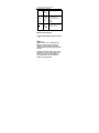
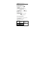
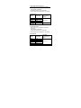
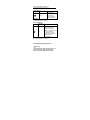
Model UT90B: OPERATING MANUAL
Table of Contents
Title
Page
Overview
Unpacking Inspection
Safety Information
Rules For Safe Operation
International Electrical Symbols
The Meter Structure
LCD Indicators
Rotary Switch
Functional Buttons
Measurement Operation
A.
AC/DC Voltage Measurement
B.
AC/DC Current Measurement
C.
Resistance Measurement
D.
Diodes Measurement
E.
Continuity Measurement
F.
Built-in Power Deficiency Charge
General Specifications
Accuracy Specifications
A.
DC Voltage
B.
AC Voltage
C.
DC Current
D.
AC Current
E.
Resistance
F.
Diodes Test
G.
Continuity Test
Fuse Replacement
Maintenance
1
Model UT90B: OPERATING MANUAL
Overview
This Operating Manual covers information on
safety and cautions. Please read the relevant
information carefully and observe all the
Warnings and Notes strictly.
Warning
To avoid electric shock or personal injury,
read the “Safety Information” and “Rules for
Safety Operation” carefully before using the
Meter.
The Model (hereafter referred to as “the
Meter”) is a 1999 counts environment protected
electrical tester with and stabilize functions,
safety operations, and reliable performance.
In addition to the conventional measuring
function, such as DC/AC voltage, resistance,
diode and continuity, it is equipped with
advanced design of charge through 220V AC or
9-12V AC or DC or solar energy. With such
design and its recycled package, the Meter can
obtain energy without battery, won’t result
chemical pollution. This is also a highly applied
digital electrical tester of good performance with
big size full functions symbols indication, full
overload protection and special appearance.
Unpacking Inspection
Open the package case and take out the Meter.
Check the following items carefully to see any
missing or damaged part:
2
Model UT90B: OPERATING MANUAL
Item
Description
Qty
1
Operating Manual
1 piece
2
Test Lead
1 pair
3
certificate
1 piece
In the event you find any missing or damage,
please contact your dealer immediately.
Safety Information
This Meter complies with GB4793 standard for
safety electrical measuring and test equipment,
and IEC61010-1: in pollution degree 2,
overvoltage category (CAT II 1000V, CAT III
600V) and double insulation.
Use the Meter only as specified in this operating
manual, otherwise the protection provided by the
Meter may be impaired.
In this manual, a Warning identifies conditions
and actions that pose hazards to the user, or
may damage the Meter or the equipment under
test.
A Note identifies the information that user should
pay attention on.
International electrical symbols used on the
Meter and in this Operating Manual are
explained on page XXX.
Rules For Safe Operation
3
Model UT90B: OPERATING MANUAL
Warning
To avoid possible electric shock or personal
injury, and to avoid possible damage to the
Meter or to the equipment under test, adhere
to the following rules:
z
z
z
z
z
z
z
z
Before using the Meter inspect the
case. Do not use the Meter if it is
damaged or the case (or part of the
case) is removed. Look for cracks or
missing plastic. Pay attention to the
insulation around the connectors.
Inspect the test leads for damaged
insulation or exposed metal. Check the
test leads for continuity. Replace
damaged test leads with identical
model number or electrical
specifications before using the Meter.
When using the test leads, keep your
fingers behind the finger guards.
Do not apply more than the rated
voltage, as marked on the Meter,
between the terminals or between any
terminal and grounding.
When the Meter working at an effective
voltage over 60V in DC or 30V in AC,
special care should be taken from there
is danger of electric shock.
Use the proper terminals, function, and
range for your measurements.
The rotary switch should be placed in
the right position and no any
changeover of range shall be made
during measurement is conducted to
prevent damage of the Meter.
Disconnect circuit power and discharge
4
Model UT90B: OPERATING MANUAL
z
z
z
z
z
z
z
all high-voltage capacitors before
testing resistance, diodes or continuity.
Charge as soon as the Meter indicator
appears to keep precision of the
readings.
Remove test leads from the test circuit
before changeover of range. Turn the
Meter power off before connect the
Meter to circuit and check the fuse
before measuring current.
When servicing the Meter, use only the
same model number or identical
electrical specifications replacement
parts.
The internal circuit of the Meter shall not
be altered will to avoid damage of the
Meter and any accident.
Soft cloth and mild detergent should be
used to clean the surface of the Meter
when servicing. No abrasive and solvent
should be used to prevent the surface of
the Meter from corrosion, damage and
accident.
Turn off the Meter when it is not in use
for a long time.
Do not use or store the Meter in an
environment of high temperature,
humidity, explosive, inflammable and
strong magnetic field. The performance
of the Meter may deteriorate after
dampened.
International Electrical Symbols
AC (Alternating Current).
DC (Direct Current).
5
Model UT90B: OPERATING MANUAL
Grounding.
Double Insulated.
Deficiency of Built-In Battery.
Warning. Refer to the Operating
Manual.
China
Technology
Supervision
Bureau, license for measuring
instrument Manufacture
Conforms to Standards of European
Union.
The Meter Structure (see figure 1)
LCD Display.
solar receiver.
Impedance optional Button.
Rotary Switch.
Input Terminals.
6 Power Button.
LCD indicators(see figure 2)
appear at AC measurement, disappear
at DC measurement.
display the minus readings.
charge indicator.
CHARGE
battery deficiency indicator.
continuity measurement indicator.
diodes measurement indicator.
7
Ω,KΩ,MΩ
Resistance unit: ohm, kilohm,
megohm
6
Model UT90B: OPERATING MANUAL
MV, V
mA, mA, A
Voltage unit: millivolt, volt
Current unit: microampere,
milliampere, ampere
Rotary Switch
Below table indicated for information about the
rotary switch positions.
Rotary
Switch
Positio
n
V
V
Ω
Function
DC voltage measurement range
from 200.0mV to 1000V.
AC voltage measurement range
from 2.000V to 750.0V.
ΩResistance measurement range
from 200.0Ω to 20.00MΩ.
Diode test.
A
A
CHARGE
Continuity test.
DC current measurement range
from 200.0µA to 20.00A.
AC current measurement range
from 200.0µA to 20.00A.
MAX: AC
Charge: 230V
220V
input charge
9-12 V : 9-12 V
input charge
Turn on/off the Meter.
Functional Buttons
Below table indicated for information about the
7
Model UT90B: OPERATING MANUAL
functional button operations.
Button
Impeda
nce
change
over
button
Measur
ing
Functi
on
Operation Performed
AC/DC
voltage
range
It is used to inspect
the resistance of
supply power under
250V
MAX.(
)
Any
rotary
switch
position
Turn the power of the
Meter on or off.
Measurement Operation
A. AC/DC Voltage Measurement (see figure
3)
Warning
To avoid harms to you or damages to the
Meter from electric shock, please do not
attempt to measure voltages higher than
1000V DC/750V AC although readings may be
obtained.
Impedance Changeover Button turn on time
should≤3 seconds. To avoid damages to the
Meter, please do not use the Impedance
Changeover Button when the measured
voltage is higher than 250V.
8
Model UT90B: OPERATING MANUAL
The DC voltage ranges are: 200.0mV, 2.000V,
20.00V, 200.0V, 1000V; The AC voltage ranges
are: 2.000V, 20.00V, 200.0V, 750.0V. To measure
AC/DC voltage, connect the Meter as follows:
1.
2.
3.
4.
5.
Insert the red test lead into the“VΩ)”
terminal and the black test lead into the
COM terminal.
Set the rotary switch to“V ”or“V ”,and
Connect the test leads across with the
power or load being measured.
The measured value shows on the
display which is an effective value of sine
wave (mean value response).
In each range, the Meter has an input
impedance of 10MΩ. This loading effect
can cause measurement errors in high
impedance circuits. If the circuit impedance
is less than or equal to 10kΩ, the error is
negligible (0.1% or less).
Manual Impedance Changeover
Button“10MΩ/400kΩ”can be used to check
inside impedance of supply power under
250V MAX.
Note
z
When AC/DC voltage measurement has
been completed, disconnect the connection
between the testing leads and the circuit
under test.
z
Pay attention to avoid harms to you from
electric shock during high voltages
measurement.
9
Model UT90B: OPERATING MANUAL
B. AC/DC Current Measurement (see figure
4)
Warning
To avoid damages to the built-in fuse and the
Meter, please do not attempt parallel connect
the test leads with any circuit while the test
leads are inserted into the current terminal.
For the safety requirement, when measure
high current, every measure time should 10
seconds and the time between two
measurements should 15 minutes.
The measurement ranges of current are:
200.0µA, 2.000mA, 20.00mA, 200.0mA and
20.00A. To measure current, do the following:
1
Insert the red test lead into the“µA mA”
or“20A”terminal and the black test lead
into the COM terminal.
2
Set the rotary switch to“A ”or“A ”,and
Connect the test leads across with the
circuit being measured.
3.
The measured value shows on the display,
it is an effective value of sine wave (mean
value response).
Note
z
Turn off the power of circuit being
measured before series connection
between the Meter and the circuit.
z
Use proper terminals and ranges for the
measurement.
10
Model UT90B: OPERATING MANUAL
z
Please use the ranges from high to low if
the current not being confirmed.
z
When current measurement has been
completed, disconnect the connection
between the test leads and measured
circuit.
C. Resistance Measurement(see figure 5)
Warning
To avoid injury to the user, please do not
attempt the voltage higher than 60V/DC or
30V/AC.
The resistance ranges are: 200.0Ω, 2.000kΩ,
20.00kΩ, 200.0kΩ, 2.000MΩand 20.00MΩ. To
measure resistance, connect the Meter as
follows:
1.
2.
3.
Insert the red test lead into the VΩ
terminal and the black test lead into the
COM terminal.
Set the rotary switch toΩ, parallel connect
the test leads across with the object being
measured.
The measured value shows on the display.
Note
z
The LCD will display “1” indicating opencircuit for the tested resistor or the resistor
value is higher than the maximum range of
the Meter.
z
To measure online resistance, please turn
off power of the circuit and discharge all
11
Model UT90B: OPERATING MANUAL
z
capacitors.
The test leads can add 0.1Ωto 0.2Ω of error
to resistance measurement. To obtain
precision readings in low-resistance
measurement, that is the range of 200.0Ω,
short-circuit the input terminals beforehand
and record the reading obtained (called this
reading as X). (X) is the additional
resistance from the test lead.
Then use the equation:
measured resistance value (Y) (X) =
precision readings of resistance.
z
When the resistance reading≥0.5Ωin the
shorten-circuit, please check for loose test
leads or other reasons.
z
For high-resistance measurement (>1MΩ),
it is normal taking several seconds to
obtain a stable reading, and it is better to
choose short measuring cable.
z
When resistance measurement has been
completed, disconnect the connection
between the testing leads and the circuit
under test.
D. Diodes Measurement (see figure 6)
Warning
To avoid injury to the user, please do not
attempt the voltage higher than 60V/DC or
30V/AC.
Use the diode test to check diodes, transistors,
and other semiconductor devices. The diode test
sends a current through the semiconductor
12
Model UT90B: OPERATING MANUAL
junction, then measures the voltage drop across
the junction. A good silicon junction drops
between 0.5V and 0.8V.
To test a diode out of a circuit, connect the Meter
as follows:
1.
2.
3.
Insert the red test lead (anode “+”) into the
VΩ
terminal and the black test lead
(cathode “-”) into the COM terminal.
, place the red
Set the rotary switch to
test lead on the component’s anode and
place the black test lead on the
component’s cathode.
For forward voltage drop readings on any
semiconductor component, the measured
value shows on the display and the unit of
diodes measurement is mV.
Note
z
In a circuit, a good diode should still
produce a forward voltage drop reading of
500mV to 800mV.
z
Connect the test leads to the proper
terminals as mentioned above to avoid
error display. The LCD will display “1”
indicating open-circuit or polarity for wrong
connection.
z
Open-circuit voltage of diodes
measurement is about 3V.
z
To measure online diode, please turn off
power of the circuit and discharge all
13
Model UT90B: OPERATING MANUAL
capacitors.
z
When diode testing has been completed,
disconnect the connection between the
testing leads and the circuit under test.
E. Continuity Measurement(see figure 7)
Warning
To avoid injury to the user, please do not
attempt the voltage higher than 60V/DC or
30V/AC.
To avoid damages to the Meter or to the
devices under test, disconnect circuit power
and discharge all the capacitors before
measuring continuity.
To test for continuity, connect the Meter as
below:
1.
Insert the red test lead into the VΩ
terminal and the black test lead into the
COM terminal.
, connect the
2.
Set the rotary switch to
test leads across with the power being
measured.
3.
The resistance of a open circuit under test
is 100Ω.
4.
The buzzer sounds continuously if the
resistance of a circuit under test is ≤10Ω,
and that shows the circuit is well
connected.
5.
The measured approximate circuit
resistance value shows on the display, the
unit isΩ.
14
Model UT90B: OPERATING MANUAL
Note
z
To measure online capacity, please turn off
power of the circuit and discharge all
capacitors.
z
z
Open-circuit voltage of continuity
measurement is about 3V.
When continuity testing has been
completed, disconnect the connection
between the testing leads and the circuit
under test.
F. Built-in Power Deficiency Charge (see
figure 8)
Warning
To avoid damage to the Meter, please do not
attempt changeover the rotary range during
charge.
The ways of charge as follows:
Power charge.
220 V
Insert the red test lead into the VΩ
terminal and the black test lead into the
COM terminal, set the rotary range to 230
V
MAX position, then insert the test
leads into the 220 V
Power plug to start
the charge.
2.
9-12
low voltage power charge.
Insert the red test lead into the VΩ
terminal and the black test lead into the
COM terminal, set the rotary range to 912
position, then insert the test leads
1.
15
Model UT90B: OPERATING MANUAL
into the 9-12
charge.
3.
Power plug to start the
Solar energy charge.
Charge through the solar energy receive
window receive solar energy from sun light.
Indicator “-6V” on the display is rated charge
voltage(comparative value), the time of 220
V
Power or 9-12
low voltage power
charge is about 5 minutes.
Note
z
The Built-in Power Deficiency indicator
appear on the display, please charge in time
to keep the precision reading of the Meter.
z
z
Choose the right way of charge.
When charge has been completed,
disconnect the connection between the
testing leads and the supply power.
General Specifications
z Maximum Voltage between any Input
Terminals and COM Terminal: 1000Vp.
z Fuse protection of µA mA terminal: 300mA
250V fast melt fuse.
z Fuse protection of 20A terminal: 20mA 250V
fast melt fuse.
z Equipped with full icons display.
z Maximum Display: Display: 1999.
z Measurement Speed: Updates 2-3 times
16
Model UT90B: OPERATING MANUAL
/second.
Range: Manual.
Polarity: Automatically display.
Over load indicator: “1”.
.
Battery Deficiency: Display
Temperature:
Operating: 0 ~40 (32 ~104 ).
Storage: -10 ~50 (14 ~122 ).
z Relative Humidity: ≤75% @ 0 - 30 ;
≤50% @ 31 - 40 .
z Supply Power: 220V
9-12
or solar
energy charge.
z Dimensions (HxWxL): 179 x 88 x 39mm.
z Weight: ? g.
z Safety/Compliances:
IEC61010: CAT II 1000V CAT III 600V.
z Certification:
CMC(94) 03000148
z
z
z
z
z
Accuracy Specifications
Accuracy ±(a% reading + b digits), guarantee
for 1 year.
Operating temperature 18 - 28 .
Relative humidity ≤75%RH.
A.DC Voltage
Range
Resolution
200mV
2V
20V
200V
0.1mV
1 mV
10 mV
100mV
Accuracy:
±(a% reading +
b digits)
±(0.5%+2)
17
Model UT90B: OPERATING MANUAL
1000V
1V
±(0.8%+3)
Remark:
●Input impedance: 10MΩ.
●Overload Protection: 1000V DC or 750V AC
continuously measure(except 200mV 230V AC).
B.AC Voltage
Range
Accuracy:
±(a% reading + b
digits)
Resolution
2V
1mV
±(0.8%+5)
20V
10mV
200V
100mV
750V
1V
±(1.0%+5)
Remarks:
●Input impedance: 10MΩ.
●Overload Protection: 1000V DC or 750V AC
continuously measure.
●Frequency response: 40Hz ~ 400Hz.
●Displays effective value of sine wave (mean
value response).
C.DC Current
Range
Resolution
200µA
0.1µA
2mA
1µA
20mA
10µA
200mA
0.1mA
20A
10mA
Remarks:
●Overload Protection:
Accuracy:
±(a% reading +
b digits)
±(1.0%+2)
±(1.2%+5)
18
Model UT90B: OPERATING MANUAL
AtµA mA range: Fuse 5×20mm F0.3A 250V.
At A range:
Fuse 6×25mm F20A 250V.
continuous measure time 10 seconds.
time between two measurements 15 minutes.
D. AC Current
Range
Resolution
Accuracy:
±(a% reading +
b digits)
200µA
0.1µA
2mA
1µA
±(1.2%+5)
20mA
10µA
200mA
0.1mA
20A
10mA
±(2.0%+5)
Remarks:
●Frequency response: 40Hz – 400Hz.
●Overload Protection:
AtµA mA range: Fuse 5×20mm F0.3A 250V.
At A range:
Fuse 6×25mm F20A 250V.
continuous measure time 10 seconds.
time between two measurements 15 minutes.
E. Resistance
Range
Resolution
200Ω
2kΩ
20kΩ
200kΩ
2MΩ
20MΩ
Remarks:
0.1Ω
1Ω
10 Ω
100Ω
1kΩ
10kΩ
Accuracy:
±(a% reading + b
digits)
±(0.8%+3)
±(1.2%+5)
19
Model UT90B: OPERATING MANUAL
●Overload Protection: 230V rms.
F. Diodes Test
Range
Resolution
1mV
Remark
Open-circuit
voltage is about 3V;
transistor PN
normal voltage is
about 0.5~0.8V.
Remarks:
●Overload Protection: 230V rms.
G. Continuity Test
Resolutio
Range
n
1Ω
Remark
Open circuit voltage is
about 3V; Set the
resistance of a open
circuit 100Ω, buzzer will
not sound; Set the
resistance of a well
connected circuit≤10Ω,
buzzer sounds
continuously.
Remark:
●Overload Protection: 230V rms.
Fuse Replacement(see figure 9)
Warning
To avoid electrical shock or injury to the user
because of wrong readings of the Meter,
please inspect the damage of fuse inside
20
Model UT90B: OPERATING MANUAL
when there is not any response on the
display during current measurement. Replace
the damaged fuse with identical model
number or electrical specifications.
To replace the fuse as follows:
1. Turn the Meter to OFF position, and remove
the test leads from terminals.
2. Take off the holster as figure 9 shows.
3. Remove the 3 screws from the case bottom,
separate the case bottom, then replace the
damaged fuse.
MAINTENANCE
This section provides basic maintenance
information including battery replacement
instruction.
Warning
Before remove the case bottom, make sure
the power is off, remove the test leads from
terminals and test circuit.
z
z
z
Periodically wipe the case with a damp
cloth and a little mild detergent. Do not use
chemical abrasives or solvents.
Please stop any operation of the Meter and
sent it outside to repair or service if there is
anything wrong.
Do not attempt to repair of service your
Meter unless you are qualified to do so and
have the relevant calibration, performance
21
Model UT90B: OPERATING MANUAL
test, and service information.
** END **
This operating manual is subject to change without
notice.
C Copyright 2001 Uni-Trend International Limited.
○
All rights reserved.
Manufacturer:
Uni-Trend International Limited
Rm901, 9/F, Nanyang Plaza
57 Hung To Road
Kwun Tong
Kowloon, Hong Kong
Tel: (852) 2950 9168
Fax: (852) 2950 9303
Email: [email protected]
http://www.uni-trend.com
22