1
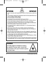
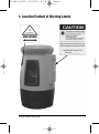
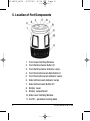
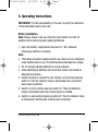
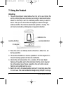
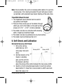
40-6600_6610
4/22/05
4:56 PM
Page 1
™
Self-Leveling 3-Line Laser Level
Model Nos. 40-6600 and 40-6610
Instruction Manual
Congratulations on your choice of this Self-Leveling 3-Line Laser
Level. We suggest you read this instruction manual thoroughly before
using the instrument. Save this instruction manual for future use.
This tool emits one laser cross and one vertical line at 90°. The tool
features quick damping, visual and audible out of range indication, and
a synchronized power-off/pendulum-locking design. Beam visibility
depends upon lighting conditions in the work area.
This is a Class II laser tool and is manufactured to comply with CFR 21,
parts 1040 .10 and 1040 .11 as well as international safety rule IEC 285.
©2005 Johnson Level & Tool
1
40-6600_6610
4/22/05
4:56 PM
Page 2
Table of Contents
1. Kit Contents
2. Features and Functions
3. Safety Instructions
4. Location/Content
of Warning Labels
5. Location of Parts/Components
6. Operating Instructions
7. Using the Product
8.
9.
10.
11.
12.
13.
14.
Self-Check and Calibration
Technical Specifications
Application Demonstrations
Care and Handling
Product Warranty
Product Registration
Accessories
1. Kit Contents
For Model No. 40-6600
Description
Self-Leveling 3-Line Laser Level
Tripod/Wall Mount Bracket
“AA” Alkaline Batteries
Tinted Goggles
Magnetic Target
Instruction Manual with Warranty Card
Soft Sided Carrying Case
For Model No. 40-6610
Description
Self-Leveling 3-Line Laser Level
Tripod/Wall Mount Bracket
“AA” Alkaline Batteries
Tinted Goggles
Magnetic Target
Laser Pole with Carrying Case
Instruction Manual with Warranty Card
Soft Sided Carrying Case
2
Qty.
1
1
3
1
1
1
1
Qty.
1
1
3
1
1
1
1
1
©2005 Johnson Level & Tool
40-6600_6610
4/22/05
4:56 PM
Page 3
2. Features and Functions
• Able to project one cross laser, and one vertical line at 90
degrees.
• Magnetic dampening compensation system.
• Laser flashes and audible alarm when product is beyond
leveling range.
• Low voltage indication with power indication lamp flashing.
• Scaled wall bracket is also available for operation on the tripod.
• Convenient rotatable base is available for both powering-on /
powering-off the unit and releasing / locking compensation
system.
3. Safety Instructions
Please read and understand all of the following instructions, prior
to using this tool. Failure to do so, may result in bodily injury.
CAUTION: If using this product with any type of tinted goggles,
please note safety warning below.
CAUTION!
Class II Laser Product
Max. Power Output: ≤ 1mW
Wavelength: 625-645nm
THIS TOOL EMITS LASER RADIATION.
DO NOT STARE INTO BEAM.
AVOID DIRECT EYE EXPOSURE.
©2005 Johnson Level & Tool
3
40-6600_6610
4/22/05
4:56 PM
Page 4
ATTENTION
IMPORTANT
• Read all instructions prior to operating this laser tool. Do not remove any labels from
tool.
• Use of controls or performance of procedures other than those specified herein may
result in hazardous radiation exposure.
• Do not stare directly at the laser beam.
• Do not project the laser beam directly into the eyes of others.
• Do not set up laser tool at eye level or operate the tool near a reflective surface as
the laser beam could be projected into your eyes or into the eyes of others.
• Do not place the laser tool in a manner that may cause someone to unintentionally
look into the laser beam. Serious eye injury may result.
• Do not operate the tool in explosive environments, i.e. in the presence of gases or
flammable liquids.
• Keep the laser tool out of the reach of children and other untrained persons.
• Do not attempt to view the laser beam through optical tools such as telescopes as
serious eye injury may result.
• Always turn the laser tool off when not in use or left unattended for a period of time.
• Remove the batteries when storing the tool for an extended time (more than 3 months)
to avoid damage to the tool should the batteries deteriorate.
• Do not attempt to repair or disassemble the laser tool. If unqualified persons attempt
to repair this tool, serious injury may result.
• Use only original AccuLine Pro™ parts and accessories purchased from your AccuLine
Pro authorized dealer. Use of non-AccuLine Pro parts and accessories will void warranty.
WARNING!
The tinted goggles are designed to enhance
the visibility of the laser beam. They DO NOT
offer protection to the eyes from direct exposure
of the laser beam.
4
©2005 Johnson Level & Tool
40-6600_6610
4/22/05
4:56 PM
Page 5
4. Location/Content of Warning Labels
©2005 Johnson Level & Tool
5
40-6600_6610
4/22/05
4:56 PM
Page 6
5. Location of Part/Components
1. Front Laser Emitting Window
2. Front Vertical-beam Button V1
3. Front Vertical-beam Indicator Lamp
4. Front Horizontal-beam Side Button H
5. Front Horizontal-beam Indicator Lamp
6. Side Vertical-beam Indicator Lamp
7. Side Vertical-beam Button V2
8. Battery cover
9. Battery compartment
10. Side Laser Emitting Window
11. On/Off – pendulum locking base
6
©2005 Johnson Level & Tool
40-6600_6610
4/22/05
4:56 PM
Page 7
6. Operating Instructions
IMPORTANT: It is the responsibility of the user to verify the calibration
of the instrument before each use.
Battery Installation
Note: Always check to be sure that the on/off switch is in the off
position before removing and replacing batteries.
1. Open the battery compartment and put in 3 “AA” batteries.
Please pay attention to polarity.
Note:
• The battery should be replaced with new ones once any indicators
lamp flashes while in use. The flashing lamp indicates low voltage.
• Do not charge alkaline batteries to avoid explosion.
• Used (discharged) batteries are hazardous waste and should be
disposed of properly.
2. Rotate the base to unlock the unit. Switch on horizontal-beam by
button H. Then its indicator lamp is illuminated and a horizontal
laser beam is emitted.
3. Switch on front vertical-beam by button V1. Then its indication
lamp is illuminated and front vertical beam is emitted.
4. Switch on side vertical-beam by button V2. Then its indicator lamp
is illuminated, and the side vertical beam is emitted.
©2005 Johnson Level & Tool
7
40-6600_6610
4/22/05
4:56 PM
Page 8
7. Using the Product
Unlocking
1. The unit should be in locked state when it is not in use. Unlock the
unit by rotating the base clockwise (according to indicated direction
shown on the unit) to set it to unlocked position when you start to
use it. Then you can move the unit slightly to observe through
window whether the internal mechanical system is moving. The
unit can be locked by rotating base in opposite direction.
Indicator Line
Leveling Surface
Locking Indication
3.5 degree
2. Place the unit on a relatively level surface like a table, floor, etc
during operation.
3. The surface should be as level as possible. If its tilt is beyond 3.5°,
the self-leveling system will become ineffective.
4. Unlock the unit and position it on a surface. If the laser beam
flashes with audible alarm, this indicates that the unit is beyond
its self-leveling range. Please reposition the unit until no beam
flashing and audible alarms occur.
5. Return the unit to its locked position and put it in carrying case while
it is not in use. This avoids accidental damage during transport or storage.
8
©2005 Johnson Level & Tool
40-6600_6610
4/22/05
4:56 PM
Page 9
Note: Check whether the unit is in locked position before it is put into
carrying case. If not, during movement the unit will give an alarm
as reminder, with automatic laser beam flashing at the same time.
Tripod/Wall Mount Bracket
1. The tripod/wall mount bracket can be used at
any position and height.
2. There are three screw eyes on the holder, through
which you can fix the holder on the wall by three
screws of 0.157" - 0.197" (4-5mm) diameter.
3. The holder can also be connected with elevating
staff or tripod by its bottom thread.
4. The holder can also be positioned on any level surface.
5. The holder must be tilted less than 3.5°.
8. Self-Check and Calibration
Horizontal Accuracy Self-Check
1. Set up two surveystaffs that are 16 ft.
Survey-staff B
Survey-staff A
(5m) away from each
other.
2. Set the bracket on the
tripod or elevating
pole, put the unit into
the bracket, and then
place the setup at the center between the two survey-staffs.
3. Switch on front horizontal beam button H and front vertical
beam button V1. Have their cross located on staff A and note
down the value of a1.
©2005 Johnson Level & Tool
9
40-6600_6610
4/22/05
4:56 PM
Page 10
4. Turn the unit 180°, have the cross located on staff B and note
the value of b1.
5. Move the tripod to
Survey-staff B
Survey-staff A
change the distance
between the unit and
staff A to 2 ft. (0.6m).
6. Repeat steps c, d and
note down a2, b2.
7. Calculate:
(a1-a2)-(b1-b2)=e
Note: If e>0.047" (1.2mm), the unit accuracy is beyond tolerance,
reference section 12 of this document.
Horizontal Line Accuracy Self-Check
1. Find a wall and set up the unit at 16 ft. (5m) away from the wall.
2. Set the bracket on the tripod or elevating pole, and put the unit
into the bracket and orient it at the wall.
3. Switch on front horizontal beam button H and front vertical beam
button V1, and take the cross on the wall as point A.
4. Mark out point A and point M
on the horizontal line, and the
distance between the two
points is about 8 ft. (2.5m).
5. Turn the unit to move the cross to point B that is 16 ft. (5m) away
from point A.
6. Measure the distance e between point M and the horizontal line.
Note: If e>0.118" (3mm), the unit accuracy is beyond tolerance,
reference section 12 of this document.
10
©2005 Johnson Level & Tool
40-6600_6610
4/22/05
4:56 PM
Page 11
9. Technical Specifications
Laser Wavelength
635nm±10nm
Laser Classification
Class II
Maximum Output
<1mW
Horizontal Accuracy
±3/8"/100 ft. (±3mm/10m)
Vertical Accuracy
±3/8"/100 ft. (±3mm/10m)
Working Range
Maximum 100 ft. (30m) depending upon
light conditions
Self-leveling Range
±3.5°
Power Supply
3 “AA” Alkaline Batteries
Dimensions
3-3/8" x 5-3/8" (86 x 137mm)
Weight
3.07 lbs. (1.39 Kg)
Working Temperature
14°F to 113°F (-10° C to 45° C)
Center Screw Thread
5/8" – 11
©2005 Johnson Level & Tool
11
40-6600_6610
4/22/05
4:56 PM
Page 12
10. Application Demonstrations
Reference for installing cabinets
Plumb reference for baseboard
installation
Reference for installing
suspended ceilings
Reference for installing doors
and windows
Reference for installing partitions Reference for laying tile
Reference for hanging pictures
12
Reference for dormer installation
©2005 Johnson Level & Tool
40-6600_6610
4/22/05
4:56 PM
Page 13
11. Care and Handling
• This
laser unit is a precision tool that must be handled with care.
exposing unit to shock vibrations and extreme temperatures.
• Before moving or transporting the unit, make sure that the unit
is turned off and in the locked position. Failure to lock before
transport or storage may cause damage to the units inner
mechanism and void warranty.
• Remove the batteries when storing the unit for an extended time
(more than three months) to avoid damage to the unit should
the batteries deteriorate.
• Always store the unit in its case when not in use.
• Avoid getting the unit wet.
• Keep the laser unit dry and clean, especially the laser output
window. Remove any moisture or dirt with a soft, dry cloth.
• Do not use harsh chemicals, strong detergents or cleaning solvents
to clean the laser unit.
• Avoid
12. Product Warranty
Johnson Level & Tool offers a one year limited warranty on each its
products. You can obtain a copy of the limited warranty for a
Johnson Level & Tool product by contacting Johnson Level & Tool's
Customer Service Department as provided below or by visiting us
online at www.johnsonlevel.com. The limited warranty for each
product contains various limitations and exclusions.
Do not return this product to the store/retailer or place of purchase.
Required repair/calibration must be done by an authorized AccuLine
Pro™ service center or Johnson Level & Tool's limited warranty, if
applicable, will be void and there will be NO WARRANTY. Contact our
©2005 Johnson Level & Tool
13
40-6600_6610
4/22/05
4:56 PM
Page 14
Customer Service Department to obtain a Return Material
Authorization (RMA) number for return to an authorized service center.
Proof of purchase is required.
NOTE: The user is responsible for the proper use and care of the
product.
It is the responsibility of the user to verify the calibration of the
instrument before each use.
For further assistance, or if you experience problems with this product
that are not addressed in this instruction manual, please contact our
Customer Service Department.
In the U.S., contact Johnson Level & Tool’s Customer Service
Department at 800-563-8553.
In Canada, contact Johnson Level & Tool’s Customer Service
Department at 800-346-6682.
13. Product Registration
Enclosed with this instruction manual you will find a warranty card to be
completed for product warranty registration. Product warranty registration
can also be completed online at our web site www.johnsonlevel.com.
You will need to locate the serial number for your product that is located
on the bottom of the unit. PLEASE NOTE THAT IN ADDITION TO ANY
OTHER LIMITATIONS OR CONDITIONS OF JOHNSON LEVEL &
TOOL'S LIMITED WARRANTY, JOHNSON LEVEL & TOOL MUST
HAVE RECEIVED YOUR PROPERLY COMPLETED WARRANTY CARD
WITHIN 30 DAYS OF YOUR PURCHASE OF THE PRODUCT OR ANY
LIMITED WARRANTY THAT MAY APPLY SHALL NOT APPLY AND
THERE SHALL BE NO WARRANTY.
14
©2005 Johnson Level & Tool
40-6600_6610
4/22/05
4:56 PM
Page 15
14. Accessories
AccuLine Pro™ accessories are available for purchase through
authorized AccuLine Pro dealers. Use of non-AccuLine Pro accessories
will void any applicable limited warranty and there will be NO WARRANTY.
If you need any assistance in locating any accessories, please contact
our Customer Service Department.
In the U.S., contact Johnson Level & Tool’s Customer Service
Department at 800-563-8553.
In Canada, contact Johnson Level & Tool’s Customer Service
Department at 800-346-6682.
©2005 Johnson Level & Tool
15