1
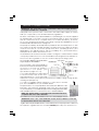
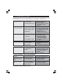
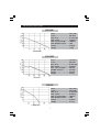
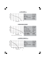
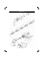
Model Nos
CBM100SS, 130SS, 250SS, 240 & 240E
CPE100P, 100TF, 120 & 130SS
HANDY PUMP 2
OPERATING & MAINTENANCE
INSTRUCTIONS
©
0406
CONTENTS
Safety Precautions ......................................................... 3
Electrical Connections .................................................. 4
Water Connections ....................................................... 5
Priming the Pump ........................................................... 7
Troubleshooting .............................................................. 8
Specifications ........................................................... 9 -11
Parts Lists and Diagrams ....................................... 12 - 29
Accessories ................................................................... 30
Parts and Service Contacts ........................................ 30
PARTS LIST & DIAGRAM
REFERENCE
Model No.
Page No.
CPE100P ................................................. 12 - 13
CPE100TF ................................................ 14 - 15
CPE130SS ................................................ 16 - 17
CPE120 ................................................... 18 - 19
CBM240 .................................................. 20 - 21
CBM240E ................................................ 22 - 23
HANDY PUMP 2 ...................................... 24 - 25
CBM100SS & CBM130SS ........................ 26 - 27
CBM250SS .............................................. 28 - 29
Please note that the details and specifications contained herein, are correct at the time of going to print. However,
CLARKE International reserve the right to change specifications at any time without prior notice.
When disposing of this product, ensure it is disposed of according to all local ordinances.
© Copyright CLARKE International. All rights reserved. February, 1998
2
Thank you for purchasing this CLARKE Water Pump, which is a general purpose
pump, suitable for a variety of applications involving the transfer of clean, cold
water ONLY (up to a maximum of 35oC) - for domestic and gardening applications.
This manual covers a range of pumps as shown on the front cover. Please read it
thoroughly and ensure you are familiar with all aspects relating to your particular
pump, before its’ connection and use. This will ensure the safe and proper
installation of the pump, and assist it in providing a long, trouble free performance.
GUARANTEE
This CLARKE product is guaranteed against faulty manufacture for a period of 12
months from the date of purchase. Please keep your receipt as proof of purchase.
This guarantee is invalid if the product is found to have been abused or tampered
with in any way, or not used for the purpose for which it was intended.
Faulty goods should be returned to their place of purchase. No product can be
returned to us without prior permission. This guarantee does not effect your
statutory rights.
SAFETY PRECAUTIONS
1.
Ensure the pump is installed in a horizontal position with the outlet facing
vertically upwards, and except for the portable Handy Pump, it should be
firmly anchored via its fixing screws.
2.
Ensure there is an adequate air flow around the pump. DO NOT mount it in an
enclosed atmosphere.
3.
Ensure all water pipes - supply or discharge - are adequately supported
where necessary, so as not to put a strain on the pump connections.
4.
DO NOT allow the pump to run dry, as this will cause serious damage to the
pump seals.
5.
Ensure the inlet to the pump is completely unrestricted.
6.
Ensure the pump is protected from the elements, neither the motor nor the
electrical terminal box is intended to be waterproof.
7.
Ensure that all pipes are protected against damage where necessary, and
that they are suitably lagged to avoid the possibility of freezing during cold
weather.
3
ELECTRICAL CONNECTIONS
WARNING
THIS EQUIPMENT MUST BE EARTHED
This appliance, which is provided with a 3-pin BS 1363 plug, should be connected
to a standard domestic 13 amp, 230 volt (50Hz), electrical supply and we strongly
recommend that this be done through a Residual Current Device (RCD).
Should the plug require renewing at any time, the wires should be connected in
accordance with the following colour code:
Green & Yellow .............. Earth or marked with a letter “E” or Earth symbol “
”
Blue .................................. Neutral or terminal marked with a letter “N”
Brown .............................. Live or terminal marked with a letter “L”
FUSE RATING
The fuse in the plug must be replaced with one of the same rating (13 amps)
and this replacement must be ASTA approved to BS1362.
IMPORTANT:
If this appliance is fitted with a plug which is moulded onto the electric cable (i.e.
non-rewirable) please note:
1. The plug must be thrown away if it is cut from the electric cable. There is a
danger of electric shock if it is subsequently inserted into a socket outlet.
2. Never use the plug without the fuse cover fitted.
3. Should you wish to replace a detachable fuse carrier, ensure that the correct
replacement is used (as indicated by marking or colour code).
4. Replacement fuse covers can be obtained from your local dealer or most
electrical stockists.
We strongly recommend that this machine is connected to the mains
supply through a Residual Current Device (RCD).
EXTENSION CABLES
Ensure that extension cable insulation is rubber or neoprene, and that the cross
section of each conductor is at least 2.5mm2. The maximum length of the cable
should not exceed 25 Metres.
If the electrical connections are outdoors, then the plug AND socket MUST be of a
BS approved waterproof design.
WARNING
DO NOT ATTEMPT ELECTRICAL INSTALLATION WORK IF YOU ARE IN ANY DOUBT AS
TO HOW IT SHOULD BE DONE PROPERLY. CONSULT A QUALIFIED ELECTRICIAN.
4
WATER CONNECTIONS
IMPORTANT: The pump must not be connected to the power supply until the
hose/pipe installation is completed.
If any part of the system is to be connected to the mains water supply, do ensure
that you comply with your local water authority regulations.
Because of the variety of possible installations, no plumbing accessories are supplied
as standard with your pump, (except for the Handy Pump 2, which is provided
with a 4 metre inlet hose complete with a foot valve and filter). However,
accessories designed specifically for this range of pumps are available from your
CLARKE dealer and are listed on page 30.
The pump must always be installed and operated in a horizontal position i.e. with
the outlet port facing vertically upwards. The fixing holes in the base should be
used as necessary to secure the pump firmly in its operating position. (Not
applicable to the Handy Pump 2, which is portable). Also, ensure that there is
adequate air circulation around the motor.
Avoid situations where there is the risk of water coming into contact with the outside
of the pump. Neither the motor or the terminal box are designed to be waterproof.
These notes are for guidance on how to achieve a proper working system.
The schematic diagram opposite illustrates
Outlet Adapter
a typical pipework installation.
The suction lift i.e. the vertical distance
between the water level and the pump
should not exceed the distance
specified for your pump. (See
Specifications, pages 9 to 11).
A foot valve and filter should be fitted
to the lower end of the suction hose,
as illustrated below, so as to help retain
water in the suction system and to prevent the possibility of large foreign bodies
entering the pump body.
A 1” BSP hose adapter will be required for connection to the inlet
port. This is available from your CLARKE dealer.
The performance of your pump will be effected by the diameter of the
inlet pipe - any restriction will greatly reduce the flow. We strongly
recommend that you use a diameter pipe which is as large as practicable,
with a suitable reducer for connection to the 1” BSP inlet adapter.
Filter
Foot
Valve
NOTE: The Handy Pump 2 is provided with a 4 metre inlet hose
complete with a foot valve and filter.
The delivery hose should be attached to the outlet adapter which is supplied.
IMPORTANT: In the case of the CBM250SS model, the hose MUST rise vertically
for 70cm before elbows are connected.
A gate valve may be installed in-line on the delivery side of the pump which can be set
as required to regulate the flow of water. DO NOT place any such restriction on
5
the suction side of the pump unless it is an isolator valve in a gravity fed system.
It is IMPORTANT to note also, that these pumps should not be operated with the
delivery valve completely closed.
To prevent unnecessary strain or possible distortion to the pump, ensure that
adequate support is provided to the hoses and/or pipes. Remember they will be
considerably heavier when filled with water.
Should sand, chemical or other contaminants come into contact with the pump,
flush through with cold clean water as soon as possible.
Protect the pump and pipework from freezing. The formation of ice may cause
serious damage.
Where the pump is to be a permanent fixture, the fittings to the pump MUST be
flexible, i.e. a short piece of hose should be inserted between rigid metal pipework
and the pump.
It is strongly recommended that in addition to the coarser foot filter, an inlet filter
should be fitted to prevent the possibility of any foreign body from entering the
pump. This is particularly important in the case of multi stage pumps CBM240,
CBM240E & CBM250SS. A filter specifically designed for all pumps in the range is
available from your CLARKE dealer - see Accessories on page 30.
The filter bowl is transparent allowing a visual check as to the condition of the filter
cartridge. The filter cartridge is a washable net type, with a rated filtration of 60
microns, suitable for the efficient removal of suspended particles such as sand.The
filter is NOT designed to filter mud, sludge etc.
CPE100TF, CBM100SS, CBM130SS, CBM250SS and CBM240E.
These pumps are set up as BOOSTER PUMPS, described in greater detail below, and
are provided with non-return valves. Additionally, 100TF & 240E models are provided
with filters, (optional accessories for SS models - see your Clarke dealer for details).
Non-return valves and filters are connected to the inlet port as follows:
Screw the non return valve into the inlet port, ensuring the arrow, stamped on the
valve points inwards towards the inlet port. Tighten the valve, BUT DO NOT
OVERTIGHTEN, then screw the filter on to the valve - again DO NOT OVERTIGHTEN.
The filter should hang vertically when completed.
CBM240E
This pump is set up as a BOOSTER Pump by incorporating the CLARKE EPC 1000
HYDROTRONIC UNIT - a computerised electronic device which automatically
switches the pump ON and OFF whenever a tap, or other restriction in the outlet
side of the pump, such as a spray lance etc., is turned ON or OFF.
Please ensure you are thoroughly familiar with the operation of this device by reading
the enclosed leaflet describing its’ operation and maintenance, before you operate the
pump. It is important to note that in order for the hydrotronic unit to operate correctly, the
maximum head ABOVE THE OUTLET OF THE HYDROTRONIC UNIT, is 14 metres.
i.e. Although the pump is capable of delivering water to a maximum head of 48
metres, the hydrotronic unit will not switch the pump ON if the vertical height
above outlet of the unit is greater than 14 metres.
6
CPE100TF, CBM100SS, CBM130SS and CBM250SS
These units are set up as a BOOSTER pumps by utilising an air chamber with a pressure
regulator to provide a constant pressure at the outlet. All models are provided with
non-return valves and Model CPE100TF is also provided with an inlet filter.
The pumps will automatically cut in when the water pressure reduces to 2.0 Bar,
and cut out when the pressure reaches 3.5 Bar. (These pressures are 3.5 and 5.2
bar respectively for Model CBM250SS). These pressures are factory set and must
not be altered. The pump may continue to operate for a short while, after the tap
is turned off, until the cut-out pressure is reached.
In order for the system to operate correctly, it is necessary to pressurise the air
chamber to 1.5 Bar (22psi), which is carried out as follows:
Unscrew the large protection cap on the end of the air chamber to reveal the air
valve, and use an air line or foot pump to charge the chamber to the specified
pressure, checking with a standard air pressure gauge until satisfied. Remember
to replace the protection cap when completed.
IMPORTANT: This procedure MUST be carried out BEFORE connecting to the water supply.
PRIMING
When suction lift is used to draw water into the pump it is essential that all
connections and hoses are completely air tight, otherwise the system will not work.
Although the pump is a ‘self priming’ type, it is nevertheless necessary to completely
fill the inlet side of the pump with water before being started for the first time, or if
the system has been drained for maintenance or repair purposes. This is known as
priming the pump and is carried out as follows :1. Locate and remove the small filler plug, situated on the top of the pump
chamber, and slowly fill the pump with water until all air is expelled.
NOTE: If a filter is fitted to your pump it is recommended that you remove the
brass plug on top of the unit, and fill the bowl with water.
In the case of the CPE100P, no filler plug is provided, and the pump body is
therefore filled through the outlet port before its’ connection
2. Adjust any device which may be fitted to the outlet side of the pump, so as to
ensure as great a flow as possible.
3. Switch on the pump and check for leaks. Water should start to flow through
the system after a short while. If, after 2-3 minutes, depending upon the suction
depth, water does not flow, check to ensure:
a) The inlet pipe is completely secure and completely free from defects.
Even a pin hole could prevent the pump from drawing water. This is the
most common problem encountered when operating water pumps.
b) The pump body has been primed correctly, and is completely filled with water.
NOTE: If the pump is gravity or pressure fed, priming will not be necessary, as
the pressure of water will purge the system of air.
7
TROUBLE SHOOTING
REMEMBER that rate of flow is dependant upon the head - i.e. the greater the head
the lower the flow. Check the specifications for your pump on pages 9 to 11.
The pump does not run
1. No mains supply
2. Impeller seized / blocked
Thermal overload has
operated switching OFF
1. Incorrect mains voltage
2. Impeller seized / blocked
3. Pump ran with hot water
4. Pump ran dry
Pump runs but no output
1. Air in pump housing
2. Suction fault
3. Suction height too great
Low or no Flow
1. Blocked inlet pipe
2. Blocked impeller
1. Check fuse - replace if
necessary (13 Amp).
2. Disconnect pump from mains,
disassemble, and clear
blockage.
1. Check and rectify.
2. Disconnect pump from mains.
disassemble, & clear blockage.
3. Do not pump water at a temp.
greater than 35OC.
4. NEVER run your pump dry.
Investigate the cause & rectify.
1. Disconnect from the mains and
prime pump correctly.
2. Verify that suction pipe is
completely sound and all
connections are air tight.
3. Check height is within spec. for
your pump.
1. Investigate and rectify.
2. Disassemble pump and clear
blockage.
3. Check that head is within spec.
3. Head too high
PUMPS WITH HYDROTRONIC UNIT
Pump runs non-stop
1. Leaks on output side
or cuts in and out
rapidly
2. Non-Return valve faulty.
1. Ensure connections are water
tight. Check to ensure no taps
are leaking. Smallest leak will
cause Hydrotronic unit to
operate.
2. Check and rectify.
CPE100TF, CBM100SS, CBM130SS and CBM250SS
Pump switches on and
off rapidly
1. Low air pressure
2. Membrane damaged
1. Check pressure and re-charge.
2. Consult your CLARKE dealer.
Pump switches on & off
when no water is being
drawn.
1. Leak in output side.
2. Non-Return valve faulty.
1. Investigate and rectify.
2. Check and rectify.
Pump does not switch
OFF
1. Pressure switch faulty
2. No water at pump inlet
3. Faulty Impeller
1. Consult your CLARKE dealer.
2. Check for blockage.
3. Disasemble and investigate.
Should you still experience problems, then contact your Clarke dealer, or CLARKE
International Service Department for advice.
8
SPECIFICATIONS
CPE100P
Motor ...............................
Power ..............................
Max. Flow ........................
Max. Head ......................
Max. Suction Height ......
Max Output Pressure .....
Part No. ...........................
Weight .............................
230V 50Hz
700 Watts
50 Litres/min
42 Metres
9 Metres
6 Bar
7230630
6.8 Kg
CPE100TF
Motor ...............................
Power ..............................
Max. Flow ........................
Max. Head ......................
Max. Suction Height ......
ON/OFF Pressure ............
Part No. ...........................
Weight .............................
230V 50Hz
700 Watts
50 Litres/min
35 Metres
9 Metres
2/3.5 Bar
7230640
14.4 Kg
CPE120
Motor ............................... 230V 50Hz
Power .............................. 1000 Watts
Max. Flow ........................ 61 Litres/min
Max. Head ...................... 50 Metres
Max. Suction Height ...... 9 Metres
Max Output Pressure ..... 8 Bar
Part No. ........................... 7230650
Weight ............................. 10.6 Kg
9
CPE130SS
Motor ...............................
Power ..............................
Max. Flow ........................
Max. Head ......................
Max. Suction Height ......
Part No. ...........................
Weight .............................
230V 50Hz
1250 Watts
81 L/min
50 Metres
9 Metres
7230680
19.6 Kg
CBM 240 & 240E
Motor ...............................
Power ...............................
Max. Flow ........................
Max. Head (240) ..............
Max Head (240E) ............
Max. Suction Height .......
Max Pressure (240) ........
ON/OFF Pressure (240E)
Part No.CBM240 .............
Part No.CBM240E ...........
Weight (240/240E) ..........
* Max. head above Hydrotronic unit
230V 50Hz
1000 Watts
101 L/min
48 Metres
14 Metres*
7.5 Metres
8 Bar
1.6/4.8 Bar
7230660
7230670
10.9/11.8 Kg
HANDY PUMP 2
Motor ...............................
Power ..............................
Max. Flow ........................
Max. Head ......................
Max. Suction Height ......
Part No. ...........................
Weight .............................
10
230V 50Hz
1000 Watts
61 L/min
50 Metres
9 Metres
7230690
12.2 Kg
CBM100SS
Motor ............................. 230V 50Hz
Power ............................ 700 Watts
Max. Flow ...................... 51 L/min
Max. Head .................... 35 Metres
Max. Suction Height .... 9 Metres
Air Reservoir .................. 24 Litres
ON/OFF Pressure .......... 2.0/3.5 Bar
Part No. ......................... 7238000
Weight ........................... 15.2 Kg
CBM130SS
Motor ............................ 230V 50Hz
Power ........................... 1250 Watts
Max. Flow ..................... 80 L/min
Max. Head ................... 50 Metres
Max. Suction Height ... 9 Metres
Air Reservoir ................. 24 Litres
ON/OFF Pressure ......... 2.0/3.5 Bar
Part No. ........................ 7238010
Weight .......................... 18.2 Kg
CBM250SS
Motor ............................. 230V 50Hz
Power ............................ 1250 Watts
Max. Flow ...................... 100 L/min
Max. Head .................... 60 Metres
Max. Suction Height .... 9 Metres
Air Reservoir .................. 24 Litres
ON/OFF Pressure .......... 3.5/5.2 Bar
Part No. ......................... 7238020
Weight ........................... 19.2 Kg
11
CPE100P
12
CPE100P
Item Description
1
2
3
4
5
6
7
8
9
10
11
12
13
14
15
16
17
18
19
20
21
22
23
24
25
26
27
28
29
30
31
32
33
34
35
36
37
38
39
40
41
42
Qty
Pump Housing
Cap 3/8" Gas
Joint O-ring
Screw
Washer
Joint O-ring
Injector
Diffuser
Joint 0-ring
Impeller
Mechanical Seal
Flange With Handle
Nut
Joint
Flange
Bearings
Shaft w/Bearings
Stator
Gasket
Base Capacitor Holder
Capacitor
Screw
Joint O-ring
Screw
Cap Capacitor
Cable Fastener
Screw
Spring Washer
Washer
Spring Ring
Cap MEC63
Fan MEC 63
Fan Cover MEC63
Cross Screw
Switch
Cable
Joint D.9
Nut
Cable
Handle Cap
Elbow
Clip
1
1
1
6
6
1
1
1
1
1
1
1
6
1
1
2
1
1
1
1
1
4
1
6
1
1
1
3
1
1
1
1
1
4
1
1
1
1
1
1
1
1
13
Part No.
LDS3600249
LDS3500009
LDP1200004
LDP1100002
LDP1120009
LDP1200024
LDS3250011
LDS3500247
LDP1200025
LDS3250009
LDP1220003
LDS3600151
LDP1110001
LDP1240001
LDS3120007
LDP1180001
LDS3101009
LDS3410099
LDS3500199
LDS3500214
LDP1360018
LDP1100004
LDP1200021
LDP1100006
LDS3500218
LDP1510004
LDP1100055
LDP1120003
LDP1120051
LDP1120002
LDS3120004
LDP1510014
LDS3200011
LDP1100043
LDP1380001
LDP1330001
LDP1230001
LDP1510009
LDP1330013
LDS3500288
LDP1590063
LDS3500205
CPE100TF
14
CPE100TF
No. Description
Qty
Part No.
No. Description
Qty
Part No.
1
Joint ............................... 1 .. LDP1240006
2
Nipple ........................... 1 .. LDS3500202
33 Washer .......................... 1 .. LDP1120051
3
Joint ............................... 1 .. LDP1240010
34 Spring ring ..................... 1 .. LDP1120002
32 Screw ............................ 1 .. LDP1100055
4
Flexible Pipe ................. 1 .. LDP1590005
35 Rear Shield Mech 63 ... 1 .. LDS3120004
5
Joint O-Ring .................. 1 .. LDP1200010
36 Fan Mech 63 ................ 1 .. LDP1510014
6
Screw ............................ 6 .. LDP1100002
37 Fan Cover Mech 63 .... 1 .. LDS3200011
7
Washer .......................... 6 .. LDP1120009
38 Cross Screw .................. 4 .. LDP1100043
8
Pump Housing .............. 1 .. LDS3600249
39 Nut ................................. 1 .. LDP1510009
9
Joint 0-Ring ................... 1 .. LDP1200024
40 Joint D9 ......................... 1 .. LDP1230001
10 Injector .......................... 1 .. LDS3250011
41 Nut ................................. 2 .. LDP1110003
11 Diffuser .......................... 1 .. LDS3500247
42 Washer .......................... 2 .. LDP1120005
12 Joint O-Ring .................. 1 .. LDP1200025
43 Valve Cap .................... 1 .. LDS3500166
13 Impeller ......................... 1 .. LDS3250009
44 Valve ............................. 1 .. LDP1230008
14 Mechanical Seal ......... 1 .. LDP1220003
45 Screw ............................ 2 .. LDP1100005
15 Flange ........................... 1 .. LDS3600089
46 Tank ............................... 1 .. LDS3206005
16 Nut ................................. 6 .. LDP1110001
47 Manometer .................. 1 .. LDP1170001
17 Cap Handle ................. 1 .. LDS3500288
48 Joint 0-Ring ................... 1 .. LDP1200003
18 Joint ............................... 1 .. LDP1240001
49 Membrane ................... 1 .. LDP1230009
19 Flange ........................... 1 .. LDS3120007
50 Cap 1" ........................... 1 .. LDP1590013
20 Bearing ......................... 2 .. LDP1180001
51 Joint ............................... 1 .. LDP1230010
21 Shaft with Bearings ...... 1 .. LDS3101009
52 Screw ............................ 6 .. LDP1100026
22 Stator ............................. 1 .. LDS3410099
53 4 Way Flange ............... 1 .. LDS3600203
23 Gasket .......................... 1 .. LDS3500199
54 Joint O-Ring .................. 1 .. LDP1200016
24 Base Capacitor Holder . 1 .. LDS3500212
55 Pressure Switch ............ 1 .. LDP1380012
25 Capacitor ..................... 1 .. LDP1360018
56 Cable ............................ 1 .. LDP1330002
26 Screw ............................ 4 .. LDP1100004
57 Cable ............................ 1 .. LDP1330013
27 Joint 0-Ring ................... 1 .. LDP1200021
58 Clip ................................ 1 .. LDS3500205
28 Screw ............................ 6 .. LDP1100006
59 Non Ret Valve m/f 1" .. 1 .. LDS3600099
29 Cap Capacitor Holder .. 1 .. LDS3500218
60 Joint O-Ring .................. 1 .. LDP1200002
30 Spring Washer .............. 1 .. LDP1120003
61 Filter ............................... 1 .. LDP1591076
31 Cable Fastener ............ 1 .. LDP1510024
15
CPE130SS
16
CPE130SS
Item
Description
Qty
Part No.
1 ........... Pump Housing ............................................................. 1 ............... LDS3220002
2 ........... Screw 3/8" Gas ............................................................ 2 ............... LDS3500009
3 ........... Joint O-Ring ................................................................. 2 ............... LDP1200004
4 ........... Screw ............................................................................ 8 ............... LDP1100025
5 ........... Washer .......................................................................... 8 ............... LDP1120008
6 ........... Joint O-Ring ................................................................. 2 ............... LDP1200002
7 ........... Injector 130 .................................................................. 1 ............... LDS3250005
8 ........... Diffuser .......................................................................... 1 ............... LDS3500036
9 ........... Joint 0-Ring .................................................................. 1 ............... LDP1200001
10 .......... Impeller 130 ................................................................. 1 ............... LDS3150003
11 .......... Mechanical Seal ......................................................... 1 ............... LDP1220003
12 .......... Flange ........................................................................... 1 ............... LDS3600105
13 .......... Nut ................................................................................ 8 ............... LDP1110001
14 .......... Joint .............................................................................. 1 ............... LDP1240001
15 .......... Flange MEC 63/71 ...................................................... 1 ............... LDS3120001
16 .......... Bearing ......................................................................... 2 ............... LDP1180001
17 .......... Shaft w/Bearings ......................................................... 1 ............... LDS3111003
18 .......... Stator 130 ..................................................................... 1 ............... LDS3410095
19 .......... Gasket 63/71 ............................................................... 1 ............... LDS3500199
20 .......... Base Capacitor Holder .............................................. 1 ............... LDS3500214
21 .......... Capacitor .................................................................... 1 ............... LDP1360001
22 .......... Clip ................................................................................ 1 ............... LDS3500205
23 .......... Screw ............................................................................ 4 ............... LDP1100004
24 .......... Joint O-Ring ................................................................. 1 ............... LDP1200021
25 .......... Screw ............................................................................ 6 ............... LDP1100006
26 .......... Cap Capacitor Holder ............................................... 1 ............... LDS3500218
27 .......... Spring Washer .............................................................. 3 ............... LDP1120003
28 .......... Cable Fastener ............................................................ 1 ............... LDP1510004
29 .......... Screw ............................................................................ 1 ............... LDP1100055
30 .......... Washer .......................................................................... 1 ............... LDP1120051
31 .......... Spring Ring ................................................................... 1 ............... LDP1120001
32 .......... Rear Shield MEC 71 ..................................................... 1 ............... LDS3120002
33 .......... Fan MEC 71 .................................................................. 1 ............... LDP1510001
34 .......... Fan Cover MEC 71 ...................................................... 1 ............... LDS3200010
35 .......... Cross Screw .................................................................. 4 ............... LDP1100001
36 .......... Switch ........................................................................... 1 ............... LDP1380001
37 .......... Cable ............................................................................ 1 ............... LDP1310001
38 .......... Cable ............................................................................ 1 ............... LDP1330013
39 .......... Nut ................................................................................ 1 ............... LDP1510009
40 .......... Joint D9 ........................................................................ 1 ............... LDP1230001
41 .......... Elbow ............................................................................ 1 ............... LDS3600056
17
CPE120
18
CPE120
Item Description
1
2
3
4
5
6
7
8
9
10
11
12
13
14
15
16
17
18
19
20
21
22
23
24
25
26
27
28
29
30
31
32
33
34
35
36
37
38
39
40
41
42
43
Qty
Pump Housing ....................................................................... 1
Screw 3/8" Gas ...................................................................... 2
Joint O-Ring ........................................................................... 2
Screw ...................................................................................... 8
Washer .................................................................................... 8
Screw 1/4" Gas ...................................................................... 2
Joint O-Ring ........................................................................... 2
Joint O-Ring ........................................................................... 1
Injector 120 ............................................................................ 1
Diffuser .................................................................................... 1
Joint O-Ring ........................................................................... 1
Impeller ................................................................................... 1
Mechanical Seal ................................................................... 1
Flange Mec 63/71 ................................................................. 1
Nut .......................................................................................... 8
Joint ........................................................................................ 1
Exterior Flange MEC 7 ........................................................... 1
Bearing ................................................................................... 2
Shaft w/Bearings 120 ............................................................ 1
Stator 120 ............................................................................... 1
Gasket .................................................................................... 1
Base Capacitor Holder ......................................................... 1
Capacitor 120 ....................................................................... 1
Screw ...................................................................................... 4
Joint O-Ring ........................................................................... 1
Screw ...................................................................................... 6
Cover ...................................................................................... 1
Cable Fastener ...................................................................... 1
Screw ...................................................................................... 1
Spring Washer ........................................................................ 3
Washer .................................................................................... 1
Waved Ring ........................................................................... 1
Rear Shield MEC71 ................................................................ 1
Fan MEC71 ............................................................................. 1
Fan Cover MEC71 ................................................................. 1
Cross Screw ............................................................................ 4
Switch ..................................................................................... 1
Cable ...................................................................................... 1
Joint D9 ................................................................................... 1
Nut .......................................................................................... 1
Cable ...................................................................................... 1
Elbow ...................................................................................... 1
Clip .......................................................................................... 1
19
Part Number
............... LDS3600030
............... LDS3500009
............... LDP1200004
............... LDP1100002
............... LDP1120009
............... LDS3500008
............... LDP1200003
............... LDP1200002
............... LDS3250004
............... LDS3500036
............... LDP1200011
............... LDS3150002
............... LDP1220003
............... LDS3600105
............... LDP1110001
............... LDP1240001
............... LDS3120001
............... LDP1180002
............... LDS3111002
............... LDS3410058
............... LDS3500199
............... LDS3500214
............... LDP1360002
............... LDP1100004
............... LDP1200021
............... LDP1100006
............... LDS8500218
............... LDP1510004
............... LDP1100055
............... LDP1120003
............... LDP1120051
............... LDP1120001
............... LDS3120002
............... LDP1510001
............... LDS3200010
............... LDP1100001
............... LDP1380001
............... LDP1310001
............... LDP1510009
............... LDP1510008
............... LDP1330013
............... LDS3600056
............... LDS3500205
CBM240
20
CBM240
No. Description
Qty
Part No.
No. Description
Qty
Part No.
1
Flange Mc 1" Gas ............. LDS3500280
28 Bearing ............................... LDP1180006
2
Screw 3/8" Gas .................. LDS3500009
29 Shaft With Bearings ........... LDS3111009
3
Joint O.ring ........................ LDP1200004
30 Stator .................................. LDS3410207
4
Cross Screw ........................ LDP1100040
31 Gasket 63/71 ..................... LDS3500199
5
Spring-washer .................... LDP1120021
32 Base Capacitor Holder .... LDS3500214
6
Joint O-ring ........................ LDP1240016
33 Capacitor .......................... LDP1360002
7
Joint O-ring ........................ LDP1200014
34 Clip ...................................... LDS3500205
8
Joint O-ring ........................ LDP1200039
35 Screw .................................. LDP1100004
9
Adjuster .............................. LDS3500402
36 Joint O-ring ........................ LDP1200021
10 Spring .................................. LDP1130006
37 Cap Capacitor Holder .... LDS3500218
11 Counterflange .................. LDS3500403
38 Spring-washer .................... LDP1120003
12 Pipe Mc .............................. LDS3500284
39 Cable Fastener ................. LDP1510004
13 Nut ....................................... LDP1110009
40 Earth Screw ........................ LDP1100055
14 Washer ................................ LDP1120014
41 Washer ................................ LDP1120051
15 Impeller ............................... LDS3250027
42 Waved Ring ....................... LDP1120001
16 Diffuser ................................ LDS3250006
43 Spring-washer .................... LDP1120030
17 Washer ................................ LDP1120028
44 Fan Mec 71 ........................ LDP1510001
18 Ring ..................................... LDP1120022
45 Fan Cover Mec 71 ............ LDS3200010
19 Washer ................................ LDP1120027
46 Screw .................................. LDP1100046
20 Mechanical Seal ............... LDP1220003
47 Switch ................................. LDP1380044
21 Pump Housing ................... LDS3600121
48 Cable Blue ......................... LDP1310001
22 Handle Mc ......................... LDS3500286
49 Joint D9 ............................... LDP1230001
23 Handle Cap Mc ................ LDS3500287
50 Nut ....................................... LDP1510009
24 Screw .................................. LDP1100006
51 Cable Uk Plug .................... LDP1330013
25 Nut ....................................... LDP1110013
52 Elbow .................................. LDS3600056
26 Joint .................................... LDP1240014
53 Joint O-ring ........................ LDP1200002
27 Anterior Flange Mec 71 ... LDS3120001
21
CBM240E
22
CBM240E
No. Description
Qty
Part No.
No. Description
Qty
Part No.
1 Filter
LDP1591076
29 Shaft With Bearings
LDS3111009
2 Cross Screw
LDP1100040
30 Stator
LDS3410207
3 Nipple
LDP1590023
31 Gasket 63/71
LDS3500199
4 Joint O-ring
LDP1200002
32 Base Capacitor Holder
LDS3500212
5 Spring-washer
LDP1120021
33 Capacitor
LDP1360002
6 Screw 3/8" Gas
LDS3500009
34 Screw
LDP1100004
7 Joint O-Ring
LDP1200004
35 Joint O-Ring
LDP1200021
8 Flange MC 1" Gas
LDS3500280
36 Cap Capacitor Holder
LDS3500218
9 Joint O-Ring
LDP1240016
37 Spring-washer
LDP1120003
10 Joint O-Ring
LDP1200014
38 Cable Fastener
LDP1510004
11 Counterflange
LDS3500403
39 Earth Screw
LDP1100055
12 Pipe Mc
LDS3500284
40 Washer
LDP1120051
13 Nut
LDP1110009
41 Waved-Ring
LDP1120001
14 Washer
LDP1120014
42 Spring-washer
LDP1120030
15 Impeller
LDS3250027
43 Fan Mec 71
LDP1510001
16 Diffuser
LDS3250006
44 Fan Cover Mec 71
LDS3200010
17 Washer
LDP1120028
45 Screw
LDP1100046
18 Ring
LDP1120022
46 Joint D9
LDP1230001
19 Washer
LDP1120027
47 Nut
LDP1510009
20 Mechanical Seal
LDP1220003 48 Cable
LDS1330040
21 Pump Housing
LDS3600121
49 Hydrotronic Blue
LDCK010004
22 Handle Mc
LDS3500286
50 Elbow
LDS3600056
23 Handle Cap Mc
LDS3500287
51 Clip
LDS3500205
24 Screw
LDP1100006
52 Spring
LDP1130006
25 Nut
LDP1110013
53 Joint O-Ring
LDP1200039
26 Joint
LDP1240014
54 Obturator
LDS3500402
27 Anterior Flange Mec 71
LDS3120001
55 Tab Terminal
LDP1390011
28 Bearing
LDP1180006 56 Joint O-Ring
LDP1200040
23
HANDY PUMP 2
24
HANDY PUMP 2
Item
Description
Qty
Part Number
1 ............. Pump Housing ........................................................ 1 ................ LDS3220002
2 ............. Screw 3/8" Gas ....................................................... 2 ................ LDS3500009
3 ............. Joint O-Ring ............................................................ 2 ................ PLD1200004
4 ............. Screw ....................................................................... 8 ................ PLD1100025
5 ............. Washer ..................................................................... 8 ................ PLD1120006
6 ............. Joint O-Ring ............................................................ 2 ................ PLD1200002
7 ............. Injector .................................................................... 1 ................ SLD3250004
8 ............. Diffuser ..................................................................... 1 ................ SLD3500036
9 ............. Joint O-Ring ............................................................ 1 ................ LDP1200001
10 ............ Impeller ................................................................... 1 ................ LDS3150002
11 ............ Mechanical Seal .................................................... 1 ................ LDP1220003
12 ............ Flange ..................................................................... 1 ................ LDS3600149
13 ............ Nut ........................................................................... 8 ................ LDP1110001
14 ............ Joint ......................................................................... 1 ................ LDP1240001
15 ............ Anterior Flange ....................................................... 1 ................ LDS3120001
16 ............ Shaft w/Bearings .................................................... 1 ................ LDS3111002
17 ............ Bearing .................................................................... 2 ................ LDP1180002
18 ............ Left Body ................................................................. 1 ................ LDS3500324
19 ............ Screw ....................................................................... 7 ................ LDP1100006
20 ............ Grommet D9 ........................................................... 1 ................ LDP1230003
21 ............ Stator ....................................................................... 1 ................ LDS3410054
22 ............ Cover ....................................................................... 1 ................ LDP1510026
23 ............ Screw ....................................................................... 2 ................ LDP1100004
24 ............ Screw ....................................................................... 1 ................ LDP1100055
25 ............ Spring washer ......................................................... 1 ................ LDP1120003
26 ............ Washer ..................................................................... 1 ................ LDP1120051
27 ............ Spring Ring .............................................................. 1 ................ LDP1120001
28 ............ Rear Shield .............................................................. 1 ................ LDS2130002
29 ............ Fancover ................................................................. 1 ................ LDP1510001
30 ............ Cable ...................................................................... 1 ................ LDP1330032
31 ............ Fan Cover ............................................................... 1 ................ LDS3200010
32 ............ Cross Screw ............................................................. 1 ................ LDP1100001
33 ............ Right Body ............................................................... 1 ................ LDS3500325
34 ............ Switch ...................................................................... 1 ................ LDP1380001
35 ............ Joint D20 ................................................................. 1 ................ LDP1230005
36 ............ Capacitor ............................................................... 1 ................ LDP1360016
37 ............ Strap ........................................................................ 1 ................ LDP1390009
38 ............ Cable ...................................................................... 1 ................ LDP1310021
39 ............ Connector .............................................................. 1 ................ LDP1390011
40 ............ Elbow ....................................................................... 1 ................ LDS3600056
25
CBM100SS & CBM 130SS
26
CBM100SS & CBM 130SS
No. Description
Qty Part No,
No. Description
Qty Part No,
1
Pump housing
LPS3220002
30 Screw
LPP1100006
2
Joint O.Ring
LPP1200004
31 Cap capacitor holder
LPS3500218
3
Screw 3/8" GAS
LPS3500009
32 Spring-washer
LPP1120003
4
Non-return valve M/M 1"
LPS3600098
33 Cable Clamp CBM 130SS LPP1510004
5
Tab terminal
LPP1390011
34 Earth screw
LPP1100055
6
Joint
LPP1240025
35 Washer
LPP1120051
7
Flexible pipe
LPP1690037
36 Waved ring
CBM 130SS LPP1120001
8
Joint O.Ring
LPP1200004
36 Waved-ring
CBM 100SS LPP1120002
9
Screw
LPP1100025
37 Spring-washer
LPP1120008
38 Fan
CBM 130SS LPP1510001
LPP1200002
38 Fan
CBM 100SS LPP1510014
10 Washer
11 Joint O.Ring
LPP1120030
12 Injector
CBM 130SS LPS3250005
39 Fan cover
CBM 130SS LPP1510043
12 Injector
CBM 100SS LPS3250014
39 Fan cover
CBM 100SS LPS3200011
13 Diffuser
LPS3500036
40 Screw
CBM 130SS LPP1100046
CBM 100SS LPP1100054
LPP1200001
40 Screw
15 Impeller
CBM 130SS LPS3150003
41 Cable
LPP1330008
15 Impeller
CBM 100SS LPS3150036
42 Nut
LPP1510009
LPP1220003
43 Joint d9
LPP1230001
17 Flange Mec 63/71
LPS3600385
44 Cable
LPP1330069
18 Nut
LPP1110001
45 Pressure switch
LPP1380012
19 Joint
LPP1240001
46 Joint O.Ring
LPP1200016
14 Joint O.Ring
16 Mechanical seal
20 flange
CBM 130SS LPS3120001
47 4-way flange
LPS3600380
20 Flange
CBM 100SS LPS3120007
48 Screw
LPP1100026
21 Bearing
CBM 130SS LPP1180011
49 Cap 1" GAS
LPS3500527
21 Bearing
CBM 100SS LPP1180007
50 Joint O.Ring
LPP1200049
22 Shaft w/ brgs CBM 100SS LPS3101009
51 Membrane
LPP1230022
22 Shaft w/ brgs CBM 130SS LPS3111008
52 Joint O.Ring
LPP1200003
23 Stator
CBM 130SS LPS3410208
53 Manometer
LPP1170001
23 Stator
CBM 100SS LPS3410187
54 Screw
LPP1100100
LPS3500199
55 Valve
LPP1230008
LPS3500212
56 Valve cap
LPS3500166
24 Gasket 63/71
25 Base capacitor holder
26 Capacitor
CBM 130SS LPP1360001
57 Shell stainless steel 24lt.
LPS3220018
26 Capacitor
CBM 100SS LPP1360018
58 Washer
LPP1120005
LPP1110003
27 Clip
LPS3500205
59 Nut
28 Screw
LPP1100004
62 Bracket
LPP1510049
29 Joint O.Ring
LPP1200021
63 Feet
LPP1510048
27
CBM250SS
CBM250SS
28
CBM250SS
No. Description
1
2
3
4
5
6
7
8
9
10
11
12
13
14
15
16
17
18
19
20
21
22
23
24
25
26
27
28
29
30
31
32
33
34
35
36
37
38
Qty Part No,
Tab Terminal
Joint
Flexible Pipe
Cross Screw
Spring Washer
Joint O-Ring
Flange MC 1" GAS
Joint O-Ring
Screw 3/8" GAS
Joint
Joint O-Ring
Counterflange
Jacket inox
Nut
Washer
Impeller
Diffuser
Washer
Ring
Washer
Mechanical Seal
Pump housing
Washer
Nut
Handle MC
Handle Cap MC
Screw
Joint
Nut
Anterior flange Mec 71
Bearing
Shaft with bearings
Stator
Gasket 63/71
Base capacitor holder
Capacitor
Screw
Joint O-Ring
LDP1390011
LDP1240025
LDP1690044
LDP1100039
LDP1120021
LDP1200010
LDS3500280
LDP1200004
LDS3500009
LDP1240009
LDP1200014
LDS3500403
LDP1600014
LDP1110009
LDP1120014
LDS3250027
LDS3250006
LDP1120028
LDP1120022
LDP1120027
LDP1220003
LDS3600121
LDP1120005
LDP1110003
LDS3500286
LDS3500287
LDP1100006
LDP1240014
LDP1110013
LDS3120001
LDP1180006
LDS3111010
LDS3410208
LDS3500199
LDS3500212
LDP1360001
LDP1100004
LDP1200021
No. Description
39
40
41
42
43
44
45
46
47
48
49
50
51
52
53
54
55
56
57
58
59
60
61
62
63
64
65
66
67
68
69
70
71
72
73
74
75
29
Qty Part No,
Cap Capacitor Holder
Spring washer
Cable fastener
Earth screw
Washer
Waved ring
Spring-washer
Fan Mec 71
Fan cover Mec 71
Screw
Nut
Joint D9
Valve cap
Valve
Screw
Shell stainless steel 24lt.
Manometer
Joint O-Ring
Gauge
Cap 1" GAS
Joint O-Ring
Screw
4-way flange
Joint O-Ring
Pressure switch
Cable
Cable
Clip
Spring
Joint O-Ring
Adjuster
Elbow
Feet
Bracket
Non-return valve M/M 1"
Joint O-Ring
Joint
LDS3500218
LDP1120003
LDP1510004
LDP1100055
LDP1120051
LDP1120001
LDP1120030
LDP1510001
LDS3200010
LDP1100046
LDP1510009
LDP1230001
LDS3500166
LDP1230008
LDP1100023
LDS3220018
LDP1170001
LDP1200003
LDP1230022
LDS3500527
LDP1200049
LDP1100026
LDS3600380
LDP1200016
LDP1380012
LDP1330008
LDP1330069
LDS3500205
LDP1130006
LDP1200039
LDS3500402
LDP1690030
LDP1510048
LDP1510049
LDS3600098
LDP1200002
LDP1240005
ACCESSORIES
Please contact your CLARKE dealer who will be happy to advise you regarding
the accessories listed below.
1” Foot Valve Filter ................................................................... 7950561
1” BSP Spigot Hose Connector ............................................... 7950210
1” I.D. Reinforced Hose for suction and delivery. ................ 7955010
1” I.D. Layflat Hose for delivery only. ..................................... 7955110
Non-Return Valve (male/female for CPE100P) .................... LDS3600099
Non-Return Valve (male/male fitting) ................................... LDS3600098
Filter Assembly c/w Cartridge ................................................ LDP1591072
Filter Cartridge ......................................................................... LDP1591076
SPARE PARTS & SERVICING
For Spare Parts and Service, please contact your nearest dealer,
or CLARKE International, on one of the following numbers.
PARTS & SERVICE TEL: 020 8988 7400
PARTS & SERVICE FAX: 020 8558 3622
or e-mail as follows:
PARTS: [email protected]
SERVICE: [email protected]
30
31