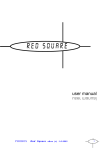
1
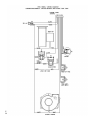
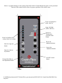
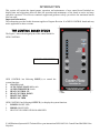
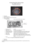
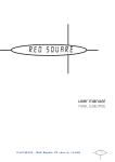
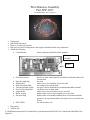
Wire Harness Assembly
Part #PP-1037
For Models HR01 (2011 to present)
•
•
•
•
•
Unplug unit
Open both side panels.
Remove existing wire harness.
May need to cut off existing molex and replace with male/female wire connectors.
Attach the following:
o Control Board
molex connector and black lead to terminal
Fuel stirrer lead
terminal
molex
o Fuel Stirrer motor
o
o
o
o
o
o
o
o
Snap disc right side
Exhaust Fan
High Limit Snap Disk
Vacuum Pressure Switch
Proof of Fire Snap Disk
Auger Motor
Room Air Fan
Electrical Plug
o NOT USED
black wire from control panel to one black lead double white lead
to black lead
not used
white wire to one lead blue wire to one lead
two orange wires to both leads
two grey wires to both leads top terminal and middle terminal
two brown wires to both leads
white wire to one lead yellow wire to one lead
double white wires to one lead pink wire to one lead
double white wires middle terminal black wire bottom terminal
green wire to top terminal other end of green wire screwed to base
of unit
red wire & white wire
• Plug unit in
• Turn on unit
F:\AESBusinessSystems\AES Technical\Piece part instructions\NPS-1005-N-9 Control Panel Kit HR01 New
Stlye.doc
F:\AESBusinessSystems\AES Technical\Piece part instructions\NPS-1005-N-9 Control Panel Kit HR01 New
Stlye.doc
Below is a graphical display of the Country Flame NPS-1005-N Control Board front panel. Each operational
function of the control board is shown for proper operation of the control center.
Power- on light glows
amber when on
Auger feed light
(amber when on)
Heat level indictor LED
(red per heat level setting)
Heat level (up) adj.
button
Heat level (down)
adj. button
Exhaust/Draft Blower
trim adjustment button
Manual or
Thermostatic
operation mode
button
Room fan
adjustment button
Auger trim
Adjustment button
ON/OFF control
button
F:\AESBusinessSystems\AES Technical\Piece part instructions\NPS-1005-N-9 Control Panel Kit HR01 New
Stlye.doc
OPERATING INSTRUCTIONS
(Without using system igniter)
NOTE: Each time the stove is started, the firepot should be checked for debris and clear air holes. Some
fuels will cause the firepot to build up more frequently making it necessary to stir and clean the firepot
more often. Do not allow ash to build up underneath the firepot.
Your control panel has three (3) separate modes of operation (switch located on top of board). The MANUAL
setting allows the operator to choose heat level setting changes without a thermostat. The T-STAT setting
allows the operator to set the high heat level setting and when the thermostat is satisfied, the unit will
automatically go to the low heat level setting. The AUTO setting allows the unit to shut completely off when
the thermostat is satisfied and re-start when the thermostat calls for heat. The AUTO setting can only be used
with wood pellets.
Before lighting your Country Flame for the first time make sure that all items are out of the hopper and firebox
area. Note: If using a wall thermostat, make sure that the thermostat is turned up above room temperature. The
unit will operate on low fire if the thermostat is turned down.
9 Load the hopper with fuel (Corn or Wood Pellets).
9 Place a small handful of wood pellets or fire starter in the firepot.
9 Squirt a small amount of fire starter gel on top of the wood pellets.
(Evenly across the wood pellets)
9 Light the fire starter gel.
9 Close the door
9 Push the “On/Off” button.
9 Turn the air intake butterfly damper to approximately ¼ inch open. (More or less as needed.)
NOTE: Priming the auger is required when the unit is new or when the hopper has completely run out of fuel.
This can be done approximately 1 minute after pushing the on/off start button. Press and hold the “auger”
button until fuel begins to drop into the firepot. When fuel begins to drop regularly, release auger button, the
auger is primed.
NOTE: The viewing door, ash pan door and hopper door must be closed and/or latched during operation or the
vacuum will not be established. If vacuum can not be established the stove will shut down and the #2 heat level
setting light will blink.
The ON/OFF button must be pushed and held for app. 6 seconds to reset the system.
The unit starts on a pre-set heat level setting. After the unit has been turned on you may select the desired heat
level. However, the feed rate heat level will not change until the unit has completed the 15 minute startup
sequence. It is recommended to burn the unit on the number #2 or #3 heat level setting for the first 30-45
minutes.
If the fire temperature has not reached proper operating temperature within the minimum cycle time (15 min.)
the auger will stop feeding, the stove will shut down and the #3 heat level setting light will blink. You will need
to press and hold the ON/OFF button for 6 seconds to start the cycle over again. If the system is set on auto
start it will attempt two startups on its own.
The draft and room air blower speed varies directly with the feed rate. The “Draft Trim” button will override
the variable fan function +/- 5 volts on all heat levels. To override, press and hold the “Draft Trim” button
along with the heat level button arrow up or heat level button arrow down, depending on desired change.
F:\AESBusinessSystems\AES Technical\Piece part instructions\NPS-1005-N-9 Control Panel Kit HR01 New
Stlye.doc
The auger feed rate on each setting is pre-programmed but may be changed if necessary. The “Auger Trim”
button will override the programmed feed rates by +/-5% on all heat levels. To override the feed rate press and
hold the ‘Auger Trim’ button along with the heat level button arrow up or heat level button arrow down,
depending on desired change.
NOTE: In case of a power outage or interruption lasting longer than 5 seconds, the “On/Off” button
must be pushed to re-engage the auger. If needed re-light the unit.
NOTE: If the fire is burning too fast and the fuel is being burned up too quickly, turn the air intake
butterfly damper closed a little to slow the fire down. This should be done in small 1/4” increments so
that the fire doesn’t change too quickly. You may also adjust the draft and auger trim to balance the
burn rate.
NOTE: When changing the heat levels there will be a delay so the system can complete the cycle before
switching to the new heat level.
NOTE: In case of a power outage, the pressure switch has tripped, the door has been opened, the hopper
door has been left open or any power interruption lasting longer than 5 seconds, the “On/Off” button
must be pushed and held for app. 6 seconds (or until you here a click) to re-engage the auger system.
IMPORTANT: The circuit board will not function properly if the outlet is not a constant 120 volt, 60
cycle power source. The outlet must be grounded properly and have the correct polarity. A polarity and
ground tester can be picked up at any hardware store to assure proper operation. If you are using a
power generator, solar power or wind generation make sure that you have a constant correct power
source.
The unit’s electrical warranty would become void if a constant power source is not available. Also make
sure that a proper surge protector is between the unit and the power source. The circuit board will not
be warranted if there is not a surge protector installed to the unit.
It is strongly recommended that you unplug the power source during times when the unit is not being
operated to protect the unit from power surges, power spikes and drops in power. It is very common for
a circuit board to work when the unit is shut off in the spring and then won’t work in the fall.
Unplugging the unit will prevent this from happening.
F:\AESBusinessSystems\AES Technical\Piece part instructions\NPS-1005-N-9 Control Panel Kit HR01 New
Stlye.doc
INTRODUCTION
This section will explain the inputs/outputs, operation, and maintenance of new control board. Included are
helpful hints and suggestions that will make the operation and maintenance of the board an easier and more
enjoyable experience. We offer our continual support and guidance to help you achieve the maximum benefit
from our units.
Important Information:
The information provided in this document applies to Program Revision 18 of NEW CONTROL board and may
not be applicable to other revisions.
THE CONTROL BOARD DESIGN
The Figure 1 shows the design/layout of the control board for
NEW CONTROL.
FIGURE 1: THE DESIGN
NEW CONTROL has following INPUT(s) to control the
system functions.
1.
ON/OFF Switch
2.
AUTO/TSTAT/MANUAL Switch
3.
AUGER TRIM/FEED Switch
4.
HEAT CONTROL UP
5.
HEAT CONTROL DOWN
6.
DRAFT/FAN TRIM
7.
HIGH FAN TRIM
NEW CONTROL has following OUTPUT(s) to display the system functions.
1.
POWER ON/OFF LED
2.
PRIME ON/OFF LED
3.
HEAT LEVEL INDICATION/ALARM LED
F:\AESBusinessSystems\AES Technical\Piece part instructions\NPS-1005-N-9 Control Panel Kit HR01 New
Stlye.doc
INPUT SWITCHES
1. ON/OFF
• When pressed in IDLE, ON/OFF switch turns ON the unit. When pressed in Ignition/Run, ON/OFF
switch turns OFF the unit.
2. TSTAT/AUTO/MANUAL
• When in TSTAT/AUTO, the unit follows TSTAT input. In MANUAL mode, HEAT levels can be
controlled by using HEAT UP/DOWN keys.
3. PRIME/FEED
• To prime press & hold, PRIME/FEED switch starts the auger if in RUN mode. This switch is only
effective in Run/Ignition mode. During Run, Auger trim can be adjusted by pressing & holding
PRIME/FEED switch and HEAT UP/DOWN switch.
4. HEAT UP/DOWN
• The heat levels can be controlled by using these switches. There are five (5) HEAT levels indicated
by HEAT LEVEL INDICATION LEDs.
5. DRAFT TRIM
• The DRAFT FAN trim can be controlled using this switch and HEAT UP/DOWN. During Run,
DRAFT trim can be adjusted by pressing & holding DRAFT trim switch and HEAT UP/DOWN
switch.
6. HIGH FAN
• The HIGH FAN trim can be controlled using this switch. During Run, HIGH FAN trim can be
adjusted to line voltage by pressing the HIGH Fan switch.
7. FUEL STIRRER
• To manually operate fuel stirrer prime press & hold, both HIGH FAN trim and HEAT UP switch.
OUPUT LEDS
1. POWER ON/OFF LED
• This LED is ON if the unit is ON, else unit is OFF.
2. PRIME/FEED LED
• If YELLOW/PRIME/FEED LED is ON, the Auger is ON and Proof of Fire is closed. If
YELLOW/PRIME/FEED LED is OFF, the auger is OFF.
3. HEAT LEVEL INDICATION LED
• Depending upon the HEAT LEVEL, respective HEAT LEVEL INDICATION LED will glow. For
reference purpose, lowest level LED is LED1 and highest level LED is LED5.
OPERATION
Power Initialized:
The exhaust fan will run approx. 12 minutes after power initialized or after a power failure. If POF open, unit
enters initial cool down mode (approximate 9-min). If POF is closed, unit will begin a Warm Re-Start to IGN.
1.0 START ON/OFF
1.1 Ignition mode:
Comb Fan 100 %, Auger @ IGN level, Igniter ON & after the 1st cycle (approximately 13 minutes), Igniter is
OFF. Comb Fan remains @ 100% Auger cycle remains @ IGN level for balance of igniter period (15-min
typical). (Additionally, Auger Setting & Room Fan may be preset for desired level during IGN period and this
will be the operation value at end of igniter period)
F:\AESBusinessSystems\AES Technical\Piece part instructions\NPS-1005-N-9 Control Panel Kit HR01 New
Stlye.doc
1.2. RUN mode:
Simultaneously @ end of 15-min Igniter period:
a) Igniter & IGN auger sequence will terminate.
b) At any time POF is closed, the Room FAN is active for cooling with 5-indpendent levels: 20%, 40%, 60%,
80%, 100% drive.
c) Manual Auger is indicated with Yellow LED and displays on period of Auger motor.
d) Heat Levels (combustion & Auger) are 5-levels with 20% incremental steps from 0% to 100%.
1.3. TSTAT operation in RUN:
Auto/T-Stat mode can be enabled or disabled by pressing TSTAT switch. If Auto/TSTAT mode enabled, unit
starts following TSTAT. Unit detects open T-Stat during RUN only and provides for Low feed combustion
regardless of pre-set Heat level. If the TSTAT is open for 30 minutes (approximate), the unit turns off and goes
to IDLE mode.
If T-Stat is closed in TSTAT/Auto mode, unit will follow manual mode.
1.4 TSTAT operation in IDLE:
Auto/T-Stat mode can be enabled or disabled by pressing TSTAT switch in IDLE.
If in Auto/T-Stat mode, unit will start if TSTAT is closed.
2.0 CYCLE OFF SYSTEM OPERATION
System can be Turned OFF by pressing On/Off switch. Fan(s) will operated 15-min typical or until POF is
OPEN for safe cooling.
2.1. Alarms:
a) If Vacuum pressure switch (APS) is OPEN during RUN for 30 seconds, AUG stops feeding and a #2 light
will start blinking showing APS Error. Unit enters COOL Down. Things to check if vacuum issue prior to
resetting the board check that access door is properly closed, ash pan door is locked and sealed, verify hose on
vacuum switch hasn’t came off, verify vacuum is not plugged.
b) If low limit (POF) is not closed at end of IGN period or during RUN for 30 seconds and a #3 will start
blinking showing POF error. Unit enters a COOL Down. Verify unit has been primed, verify fuel in hopper,
check hopper to make sure fuel is not
F:\AESBusinessSystems\AES Technical\Piece part instructions\NPS-1005-N-9 Control Panel Kit HR01 New
Stlye.doc
c) If High Limit (OT) is OPEN during RUN for 30 seconds, AUG stops feeding and a #4 will start blinking
showing OT Error. Unit enters COOL Down.
SPECIAL FUNCTIONS
3.1 AUGER OFF FUNCTION DURING IGNITION
If in Ignition, if High Fan switch is pressed, Auger turns off for two (2) minutes.
SPECIAL NOTE
A) For factory testing, igniter sequence may be bypassed by depressing HEAT UP and HEAT DOWN keys at
the same time. Unit will go directly to RUN Mode.
B) Programs can be changed only in IDLE mode, by pressing HEAT UP switch and then MODE/HIGH FAN
switch.
C) Auger does not start for two (2) minutes in Programs #1, #2, #9 and #10 (corn mode) but Auger runs for 3
minutes and then turn off for 2 minutes in Programs 3 through 8 (pellet mode).
Programs can be changed only in IDLE mode if APS (vacuum) is OPEN, by pressing HEAT UP switch and
then MODE/HIGH FAN switch.
To change the program, the system should be in IDLE mode (not in Ignition or RUN mode) with APS (vacuum)
fail.
After this, by pressing Fuel (MODE SW) switch and Heat-Up switch, the program can be changed.
The Red LEDs will blink x number of times depending upon the x number of program.
F:\AESBusinessSystems\AES Technical\Piece part instructions\NPS-1005-N-9 Control Panel Kit HR01 New
Stlye.doc