1
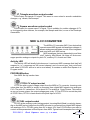
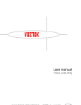
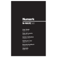
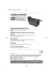
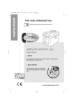
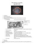
red square
user
user manual
manual
PHOBOS
Red Square e&oe (c) 1-5-2003
1
Contents
SPECIFICATION ...........................................................................3
INTRODUCTION ...........................................................................6
APPLICATIONS ............................................................................6
MONOSYNTHESISER ..................................................................6
EFFECTS PROCESSOR ..............................................................6
SAFETY INSTRUCTIONS ............................................................7
MOUNTING ...................................................................................7
MIDI CONNECTIONS ...................................................................8
REAR PANEL AUDIO CONNECTIONS .......................................8
CIRCUITS IN DETAILS.................................................................9
VCO1.............................................................................................9
VCO2...........................................................................................10
MIXER .........................................................................................12
NOISE GENERATOR..................................................................13
SUB OSCILLATOR.....................................................................13
EXTERNAL SIGNAL INPUTS ....................................................13
RING MODULATOR ...................................................................13
VC LPF........................................................................................14
EG1 AR .......................................................................................15
VCA .............................................................................................16
SAMPLE AND HOLD..................................................................18
EG2 ADSR ..................................................................................19
VC LFO .......................................................................................20
MIDI to CV CONVERTER ...........................................................21
Setting The MIDI Receive Channel and CV2 Source ..............22
MULTIPLES ................................................................................23
REAR PANEL .............................................................................25
PATCH EXAMPLES....................................................................26
CALIBRATION ............................................................................28
PHOBOS
Red Square e&oe (c) 1-5-2003
2
SPECIFICATION
Brief Overview of the Red Square:
Red Square is a patchable analogue monosynth that can also be used as an effects
processor. It has some of the advantages of a modular synth (re-wireable synth circuits,
external control, external signal routing) and advantages of a pre-patched monosynth
(easy to use, instant sound, tidy front panel). Its 1/4" jacks sockets mean it can easily be
integrated into a studio just like any synth or processor.
VCO1
Glide, PW control, sync in, saw out, square out, sub oscillator out
VCO2
Glide, PW control, saw out, square out
VCF
Low pass filter, cut-off CV, Q CV, cross modulation from VCO1, external signal in, EG
modulation
VCA
Mode switch, CV control
EG1
AR envelope with switchable sustain/release
EG2
Full ADSR envelope with normal or inverted output
VC LFO
Speed CV, saw, inverse saw, square and triangle outputs
Sample and Hold
Lag control
Noise Generator
White noise
Ring Modulation
PHOBOS Red Square e&oe (c) 1-5-2003
3
MIDI to CV Converter
With auxiliary controller CV output
Headphone output
Multiples:
2x 4 ways
1x 5 way
Many other features.
Rotary controls:
31
Push button:
1
Switches
1 push pull
2 slide
1 toggle
LEDs:
4
+ 1 neon
Jack sockets (6.35mm, mono - 1 is stereo);
52
Rugged steel and aluminium contruction
Dimensions:
5U/5HE (222mm high). Width (not inc. ears): 435mm. (inc. ears) 483mm. Depth:
145mm
Weight:
5.5Kg
Power:
240V or 110V (select when ordering), IEC socket, 2x Fuses
Accessories:
Manual, IEC power lead, patch leads
PHOBOS
Red Square e&oe (c) 1-5-2003
4
PHOBOS
Red Square e&oe (c) 1-5-2003
5
INTRODUCTION
Congratulations on buying the Phobos Red Square patchable synthesiser. Red Square
is part of the Phobos range of analogue music equipment.
Red Square's synthesiser circuitry is discrete (plus op-amps and logic ICs) and analogue.
APPLICATIONS
Red Square introduces 'modular synthesis' style sound creation for all those that are
either daunted by their complexities, do not have to space for them, or find them too expesive. Red Square gives you the oppurtunity to create a diverse range of sounds by using
patch cables to re-route the signals. Red Square is a quick and easy to use synthesiser
as its design is in a more familiar monosynth format.
MONOSYNTHESISER
The top row of controls on Red Square act as a complete (pre-patched) monosynth.
This section allows Red Square to be used straight away without having to patch any
sections together. All that is needed is a MIDI cable and an audio cable. This means Red
Square can be used straight away with no fuss or confusion as a powerful and flexible
synthesiser sound machine.
The top row synthesiser comprises VCO1, Noise, External Signal, Sub Oscillator,
VCLPF, EG1 and the VCA. The Ring Mod output also goes to the filter audio input, but its
inputs must be patched first.
The additional sections like EG2, VCO2, Ring Mod, etc, can be patched into the monosynth to create even more varied and complex sounds, or they can be used independently
or in conjuction with other synthesisers.
EFFECTS PROCESSOR
Don't just think of Red Square as just a patchable synthesiser. It is also a highly
versatile analogue effects processor. Red Square has a panel full of professional quality
6.35mm jack sockets which allows it to be integrated into your studio set-up just like any
effects processor. But instead of just another lifeless DSP processor, you have a warm,
fat, or even down right dirty analogue effects processor.
The analogue filter and ring modulator can be used as two independent effects processors or chained in series for dual effects. They can be wired into your mixing desk's effect
sends and returns just like any other effects unit. The additional sections of Red Square
can be patched in to modulate the effect on your external audio signals. All this and you
can still create and use an independent synthsiser patch too!
PHOBOS
Red Square e&oe (c) 1-5-2003
6
SAFETY INSTRUCTIONS
Please read carefully before using:
• Only use the recommended power - 240 (or 110V if ordered)
• Never handle the adaptor adaptor with wet hands
• Never excessivly bend the adaptor cable or get it trapped or place heavy objects
on it. If the adaptor cable becomes damaged, replace the adaptor.
• Ensure the unit is disconnected from the mains before moving or cleaning.
• Always disconnect the unit from the mains if there is lightning in your area.
• Ensure the unit is on a stable surface, and never place heavy objects on top of it.
• Never allow young children to operate the unit or adaptor.
• Do not use excessive force when using the controls or inserting cables to the connectors.
• The unit should not be operated in the rain or near water and should not be exposed
to moisture. If the unit is brought from a cold environment to a warm one, the unit should be
left to reach the ambient temperature. This is to allow any possible condensation moisture
inside the unit to evaporate. Although any built up moisture will not damage the unit, any
shorting may be hazardous.
• Never open the case or attempt to make repairs. Refer any servicing to a qualified
service personnel.
MOUNTING
Red Square can be rack-mounted in any standard 19” rack case. It requires 5U height,
and very little depth. Alway use all all four mounting holes so it is secured in the rack.
Alternatively, just place the unit on a stable surface. Rubber feet can be stuck on the
back to stop it sliding about.
PHOBOS
Red Square e&oe (c) 1-5-2003
7
MIDI CONNECTIONS
Although Red Square can be controlled from another analogue synthesiser or analogue sequencer (using the CV and gate inputs), it is best played from a MID keyboard
or sequencer.
Connect MIDI Out (or Thru) from your MIDI controller device to the MIDI In of Red
Square. Additional MIDI devices can be daisy chained from the Red Square MIDI Thru
socket.
REAR PANEL AUDIO CONNECTIONS
The main signal output is on the front panel, but it is also duplicated on the rear panel
so Red Square can be integrated into your studio rack set-up. Connect this socket to a
spare mixing desk input channel. In addition to the signal input socket on the front panel,
there is a direct signal input socket on the rear panel (this one has no attenuation control
though). Use this signal input socket if you wish to hardwire a signal to Red Square from
your desk's effect send.
MIDI OUT
RED SQUARE
SOUND SOURCE
Analogue synth,
AUDIO
sampler, guitar,
OUT
etc.
AUDIO
IN
MIDI IN
AUDIO
OUT
MIDI THRU
MIDI IN
Additional MIDI
modules
To main
mixer,
hard disc
recorder,
etc.
PHOBOS
Red Square e&oe (c) 1-5-2003
8
CIRCUITS IN DETAILS
Here follows details on all the sockets and controls, with brief simplified explanations
of what the circuits do. We have not gone into technical details on how and exactly what
each circuit does but tried to explain their function and effect.
Several of Red Squares signals are hardwired to other circuits for your convenience,
but note input and output sockets are still provided in most instances to retain maximum
flexibility..
VCO1
The voltage controlled oscillators (VCOs 1
and 2) produce the raw audio waveform usually
used as the initial source for sound creation.
They provide cyclic audio waveforms that can
be pitched. VCOs usually receive treatment
from a VCF to turn their harshness into pleasant audio tones.
The pitch input for VCO1 is hardwired to the
pitch CV of the MIDI to CV converter so it can
be played from a MIDI keyboard. The saw and square wave signal outputs are hardwired
to the mixer. Input and output signals are provided to enable VCO1 to be re-patched with
other circuits.
TUNE control
Controls the pitch of VCO1. Range is about +/1 2 octaves. Use this to tune VCO1 to
your other instruments.
PITCH CV LEVEL control and
CV input socket
This is a CV input for modulating the VCO pitch with a modulation CV, such as the
LFO or envelope. The depth of the modulation is changed with the LEVEL control. Higher
settings increases the modulation depth.
Usually something like an LFO is used to create vibrato effects, or the EG output to
create pitch sweeps and drum sounds. Alternatilvely, use the output of VCO2 to create
FM and metallic sound effects.
GLIDE control
Glide adds portamento to the pitch. As you play up or down the keyboard, instead
of instant pitch changes, the pitch will slide up or down from the previous frequency to
the new one played. The speed at which this happens lengthens as the GLIDE control is
increased. A zero setting produces no glide.
PHOBOS Red Square e&oe (c) 1-5-2003
9
PW control and
CV input socket
The control alters the duty cycle (a.k.a. pulse width) of the square wave output. At
roughly centre a 50% duty cycle wave is produced (square). Altering this control will vary
the pulse width. The PW can be modulated with a CV, such as the LFO signal output. Use
the triangle wave to create continuously varying pulse width to fatten up the sound.
SYNC signal input socket
Normally, you would feed a VCO signal into this socket, such as VCO2. Then try varying the pitch of VCO1 and listen to the results!
SAW LEVEL control and
signal output socket
Controls the output signal level of the sawtooth waveform fed into the filter input. The
signal is output at fixed level from the SAW socket.
SQUARE LEVEL control and
signal output socket
Controls the output signal level of the square waveform fed into the filter input. The
signal is output at fixed level from the SQUARE socket.
VCO2
VCO2 is not internally
hardwired to any of the
other circuits. It must be
patched with other circuits
or used independently.
TUNE control
Controls the pitch of VCO2. Range is about +/1 2 octaves. Use this to tune VCO2 to
your other instruments.
PITCH CV LEVEL control and
PHOBOS
CV input socket
Red Square e&oe (c) 1-5-2003
10
This is a CV input for modulating the VCO pitch with a modulation CV, such as the
LFO or envelope. The depth of the modulation is changed with the LEVEL control. Higher
settings increase the modulation depth.
Usually something like an LFO is used to create vibrato effects, or the EG output to
create pitch sweeps and drum sounds. Alternatilvely, use the output of VCO1 to create
FM and metallic sound effects.
It is also an octave scaling control. Use this to scale the octave spacing in-ine with
VCO1 (if you want both to track together).
To scale VCO2 to 1;
Patch an audio out from VCO2 to external signal in. Patch MIDI-CV Pitch out to VCO2
Pitch in. Set up the mixer, VCF and VCA so that both VCO's can be heard.
Hit note C2 on your MIDI keyboard. Use VCO2 Tune to tune the two VCO's together.
Now hit a higher note, say C4. Now use VCO2 MOD.LEVEL to scale the octave spacing
and therefore tune the two oscillators in.
GLIDE control
Glide adds portamento to the pitch. As you play up or down the keyboard, instead
of instant pitch changes, the pitch will slide up or down from the previous frequency to
the new one played. The speed at which this happens lengthens as the GLIDE control is
increased. A zero setting produces no glide.
PW control and
CV input socket
The control alters the duty cycle (a.k.a. pulse width) of the square wave output. At
roughly centre a 50% duty cycle wave is produced (square). Altering this control will vary
the pulse width. The PW can be modulated with a CV, such as the LFO signal output. Use
the triangle wave to create continuously varying pulse width to fatten up the sound.
SAW LEVEL control and
signal output socket
Controls the output signal level of the sawtooth waveform fed into the filter input. The
signal is output at fixed level from the SAW socket.
SQUARE LEVEL control and
signal output socket
Controls the output signal level of the square waveform fed into the filter input. The
signal is output at fixed level from the SQUARE socket.
PHOBOS
Red Square e&oe (c) 1-5-2003
11
MIXER
The mixer is used to bring various audio signals together
for filtering. The following audio signals are hard-wired to the
mixer; VCO1 square, VCO1 saw, noise (or sub depending on
switch NOISE/SUB status), ring modulator & external signal.
The mixer output is hard-wired to the filter audio input.
Other signals can be patch into the mixer using the external signal input socket.
NOISE / SUB level control & switch
Controls the audio level of the noise generator or sub oscillator signal that is fed into
the filter. This control has a built in push/pull switch. When it is push in, noise is selected
and routed into the filter input. When pulled out, the sub oscillator is selected and routed
to the filter input.
Whichever is selected, noise or sub, the control will alter the filter input level for that
sound source. Both signal types are still available at full level out of their repsective sockets.
Although with this method you might think only one or the other can be routed to the
filter, that is not the case. If both are needed, route the one not selected via the switch
from its output socket and back into the external signal input.
EXTernal SIGnal input control
Controls the level of the external audio that is fed into the filter. The external audio
must be patched via the EXT.SIG socket.
RM control
Controls the level of the ring modulator output that is fed into the filter. The RM output
signal is available at full level from the RM out socket.
PHOBOS
Red Square e&oe (c) 1-5-2003
12
NOISE GENERATOR
The noise generator produces white noise. This is like the hiss you hear between
radio stations. It can be patched into the S+H for random effects or to the filter for 'wind'
and other sound effects.
NOISE signal output socket
The noise generator signal is output at full level from the NOISE socket - the NOISE
/ SUB level control does not affect the level.
SUB OSCILLATOR
SUB socket
The sub oscillator signal is derived from VCO1. It generates a square wave signal that
is the same pitch, but one octave below VCO1. It can be used to beef up sounds. The sub
oscillator signal is output at full level from the SUB socket. The NOISE / SUB control does
not affect the level. When using the Sub, it is best to leave VCO1's PW unmodulated.
EXTERNAL SIGNAL INPUTS
EXTernal SIGnal input socket
When you wish to filter external audio signals, for example synthesisers, effects processor, mixer effect sends, guitar, vocals, etc.; patch the signal into this socket. The signal
can then be attenuated with the EXT.SIG level control and is then fed to the filter input.
RING MODULATOR
The ring mod (RM) is an effect that combines two sounds to
produce interesting effects. I won't go into any technical details of how
(you can read up on this if you wish). The best thing is to use it and listen to the results.
The RM needs two audio signals to work. You may wish to use VCO1 and VCO2 as
the sources. Patch their outputs to the RM X and Y inputs, and hear the result from the
RING MOD socket. Modulate either or both VCOs for maximum effect.
Alternatively, try one VCO as an input, and a second audio source such as vocals or
guitar.
PHOBOS
Red Square e&oe (c) 1-5-2003
13
Whatever your input, the output will change depending on the pitch of the VCO signal
or harmonic content.
The RM can be used independently from the rest of the synthesiser as a separate
effects processor.
RING MOD signal output socket
trol.
This is the output from the RM. It is at full level and unaffected by the RM level con-
X signal input socket
This is one of the RM signal inputs. Feed an audio signal into here, such as the VCO1
output.
Y signal input socket
This is one of the RM signal inputs. Feed an audio signal into here, such as the VCO2
output.
VC LPF
The voltage controlled low pass filter (VCLPF)
is a transistor ladder type filter. It has a sound similar to the popular 'Moog' sound. LPFs are circuits
that remove harmonics above a certain frequency
- the cut-off frequency. Use the LPF to change
the tone of the sound. The filter has a roll-off of
24dB/octave. The mixer output is hard-wired to the
filter audio input, however, external signals can still be processed using the external audio
inputs sockets. The LPF audio output is hard-wired to the VCA signal input. EG1 signal
output is wired throught the EG Amount socket.
CUT-OFF control
This sets the cut-off frequency, the point at which the LPF will start to filter-out harmonics.
EG AMNT control
The EG Amount control sets the amount EG1 will modulate the filter cut-off. When
this control is set above zero, the filter cut-off will sweep up and down with the EG signal.
PHOBOS Red Square e&oe (c) 1-5-2003
14
Use this to add some movement to the cut-off over time.
Q control and
Q input socket
Q, or resonance is a feature of adding feedback to the filter circuit. The output of the
filter is feed back into the input. Q sets the level of feedback. As the control is increase
to higher levels, the filter will self-oscillate. The oscillation frequency is set by the cut-off
control. Use Q to alter the tone of the filter effect. It can be used to create 'squiggy' sounds
and 'pulse hits'. The amount of resonance can be set using an external CV from, for example, the LFO, using the Q input socket.
X.MOD control
X.MOD (cross-modulation) sets the level of cut-off modulation received from the audio output of the mixer. Increasing this control can add crunchiness to the sound. Plenty
of audio effects can be created by experimenting with the cut-off, Q and levels and input
signals of the mixer. Put Q into self-oscillation to produce a more dramatic effect.
EXT.CV control and
CUT-OFF input socket
The cut-off frequency can be modulated with an external CV, for instance the LFO.
Patch the modulation CV to the CUT-OFF socket. The level of modulation is determined
with the EXT.CV control. There is no external modulation when the level is at zero. Increasing the control increases the level of cut-off modulation,
EG1 AR
EG1 is an AR (attack / release) envelope generator. Its output
internally hard-wired to the filter cut-off level (via the EG AMT control)
and the VCA level (via the VCA MODE switch). The trigger input is
hard-wired to the MIDI to CV converter Gate output. TRIG and CV
inputs are available to re-patch it with other circuits.
LED indicator
This wil turn on each time EG1 receives a gate signal.
PHOBOS
Red Square e&oe (c) 1-5-2003
15
SUSTAIN IN/OUT switch
IN
When selected Sustain is enabled, and the Decay/R control becomes a Release time
control. After the attack sequence has finished and the envelope has reached full level, it
will remain there as long as the Gate input is held high (i.e. note held down),
OUT
When selected there is no Sustain, and the Decay/R control becomes a Decay time
control. After the attack squence has finished, the envelope signal will decrease down to
zero at a rate deteremined by the Decay control.
ATTACK control
Controls the Attack time. This is the rate at which the envelope signal will take to reach
full level when the Gate input goes from low to high (note pressed).
DECAY/Release control
Controls the Decay or the Release time, depending on the posistion of the SUSTAIN
switch. See SUSTAIN IN/OUT switch above for more details.
TRIGger input socket
This is the Trigger or Gate signal input the sets the envelope in motion. Use a +5 to
10V gate signal.
EG1 CV signal output socket
This is the envelope CV signal output for EG1.
VCA
The Voltage Controlled Amplifier (VCA) is the circuit that is used to
change the output volume. Normally an envelope signal would be used
to do this, so the sound starts loud then gradually fades away. The filter
audio output is hard-wired to the VCA signal input.
MODE switch
EG1
When EG1 is selected, the envelope signal of EG1 is used to modulate the VCA level.
Use it if you require the VCA level to change over time.
PHOBOS
Red Square e&oe (c) 1-5-2003
16
GATE
When GATE is selected, the MIDI converter's Gate signal is used to modulate the
VCA. With this, the VCA level is either off or full on. The audio envelope would be like an
organ's, with no attack or decay time.
THRU
When THRU is selected, the VCA is left permanently on at full level. Use this setting
if you wish to use the Filter as an effects processor, to process external audio fed into
Red Square.
CV input socket
Use this socket if you wish to modulate the VCA level from a source other than EG1,
Gate, or permanently on. Maybe feed an LFO into this socket for tremelo type effects.
Usually it is best to put the VCA Mode switch to Gate when using this socket.
SIGNAL output socket
This is the main audio output of Red Square. This is the socket you would use to connect it the your mixer. It is the output from the VCA, which is the last circuit in the signal
chain. The signal level is affected by the Volume control (see below).
VOLUME control
This sets the volume of Red Square, i.e. the output level from the VCA that is output from the SIGNAL output socket. It also controls the output level for the Headphone
socket.
Headphone output socket
This is a stereo output for private headphone listening. Level is controlled with the
VOLUME control, which also controls the SIGNAL output level too. Please note, the main
SIGNAL output will still be active when headphones are used, so you may wish to disconnect the SIGNAL output, or mute Red Square on your mixer. Ensure the level is not too
high before putting on the headphones! Turn the level to zero first, then slowly increase
it to a comfortable level.
PHOBOS
Red Square e&oe (c) 1-5-2003
17
SAMPLE AND HOLD
The sample and hold (S+H) circuit is for CV processing. It is entirely independent from all the other circuits,
and must be patched to be used.
LAG control
This adds slew/portamento to the S+H output. The voltage will 'glide' from one level
to the next, smoothing out the voltage changes.
input LEVEL control and
signal INPUT socket
The LEVEL control attenuates the input voltage coming in the INPUT socket. Typical sources to use for the S+H are noise (for random voltage effects) or maybe an LFO
output (for a stepped LFO signal). If the input signal is too loud, the S+H may not function correctly (producing interesting results!) so if necessary, reduce the input level to a
satisfactory level.
CLOCK input socket
Input a clock signal into the CLOCK input. Maybe use a square wave from an LFO,
or the GATE output of the MIDI to CV converter. Each time a clock signal is received, the
S+H will sample the voltage at the INPUT socket, and hold that level at the OUTPUT until
the next clock signal is received.
OUTPUT socket
This is the S+H signal output.
Use
The most typical use of a S+H is to produce random voltages;
Patch the Noise output to the S+H INPUT.
Patch LFO Square wave to the S+H CLOCK input.
Turn LAG to zero.
Patch the S+H OUTPUT to, for example, the VCO CV input.
Increase the S+H LEVEL input control to a suitable level.
PHOBOS
Red Square e&oe (c) 1-5-2003
18
EG2 ADSR
EG2 is a full ADSR envelope
generator with normal and inverted
outputs. It is entierley indpendent
from all the other circuits, and must
be patched with them to be used.
LED indicator
This indicator shows the output status of the envelope socket, varying in brightness
as the CV signal changes.
ATTACK control
After a Gate signal is received at the GATE input, Attack sets the time it takes the
envelope signal to rise to maximum value from zero.
DECAY control
This sets the time it takes the envelope signal to decrease from the peak level (after
the Attack time has complete) to the Sustain level.
SUSTAIN control
This sets the level at which the envelope signal will settle at after the Decay time has
finished. The envelope signal will remain at the Sustain level as long as the Gate signal
is present.
RELEASE control
When the Gate signal is off, Release sets the time the envelope signal takes to decrease to zero from the Sustain level.
LEVEL control
This sets the envelope output signal level for both the normal and inverted outputs.
Normal output socket
Is the output for normal (positive) envelope signal.
PHOBOS
Red Square e&oe (c) 1-5-2003
19
Inverted output socket
Is the output for the inverted (negative) envelope signal.
VC LFO
The Voltage Controlled Low Frequency Oscillator (VCLFO) is basically identical to a VCO,
except that it produces periodic wave forms of
low frequency, typically sub-audio. These slow
cyclic waveforms are used for modulating other
circuit parameters, for example, for sweeping the
filter cut-off up and dowm, either slowly for a nice
sweep, or faster for a 'wah-wah' type effect. It could be used to modulate the VCO pitch
for vibrato, or the VCA level for tremelo. It could even be used to trigger the sample and
hold or the envelope generator.
SPEED control
This sets the frequency (speed) of the VC LFO.
SPEED LED indicator
This wil turn on each time the LFO signal is at a positive voltage, indicating the speed
of the LFO waveform.
SPEED CV input socket
The speed of the LFO can be changed using another CV, for example an EG output
signal can be used to change the speed of the LFO over a period of time.
Sawtooth waveform output socket
Is the output for sawtooth CV signal.
Inverse Sawtooth waveform output socket
Is the output for inverse sawtooth CV signal. It is the same as the sawtooth output,
except the wave form is inverted.
PHOBOS
Red Square e&oe (c) 1-5-2003
20
Triangle waveform output socket
Is the output for triangle CV signal. This wave is more suited to smooth modulation
changes, e.g. vibrato, filter sweeps.
Square waveform output socket
Is the output for square wave CV signal. This is suitable for sudden changes of CV,
or for triggering other devices, for example, the Sample and Hold, or one of the Envelope
Generators.
MIDI to CV CONVERTER
The MIDI to CV converter (MCV) is a device that
converts some MIDI signals into analogue voltages. It
allows analogue synthesiser circuits to be integrated
and used with your MIDI set-up.
MIDI messages that are responded to are Note
on/off, Velocity, Mod Wheel, All notes off. Note messages provide analogue outputs for pitch CV, auxiliary CV, Accent and Gate.
Activity LED
The Activity LED will briefly light whenever it receives a MIDI message that itself will
respond to, i.e. a message on the correct channel, and of correct type, note on/off and
mod wheel (if CC/VEL source is set to mod wheel). It remains on when Red Square is in
Program mode.
PROGRAM button
See 'MIDI Set-Up' section later.
PITCH CV output socket
CV1 is the pitch control voltage output from the MIDI to CV converter. Incoming note
value data from the MIDI In socket is converted from digital MIDI signals into analogue
CV's. The pitch CV varies from -2V to about 8V. The scaling is 1V per Octave. This means
as you go up one octave, the output voltage goes up by 1V. Use PITCH to control the pitch
of VCO2. Note, PITCH is hard-wired to the pitch input of VCO1.
CC/VEL output socket
CC/VEL is the auxiliary control voltage output. Incoming Mod Wheel (or velocity, dependig on the MIDI set-up) data from the MIDI In socket is converted from digital MIDI signals
into analogue CV's. CC/VEL varies from 0V to about 10V. Use CC/VEL when you want to
control certain parameters of Red Square from MIDI. Typical useful examples are velocity
PHOBOS
Red Square e&oe (c) 1-5-2003
21
to control filter cut-off (great for filter dynamics), Mod Wheel to control LFO speed, etc.
GATE output socket
Incoming note on/off data from the MIDI In socket is converted from digital MIDI signals into analogue Gate signals. Gate signals are either on (about 10V) or off (0V). Gate
is usually used to trigger the envelopes or sample and hold circuits. Note Gate is hardwired to EG1's trigger input. Gate can also be used to control an of the other CV inputs,
like filter cut-off or LFO speed.
ACCENT output socket
When a MIDI note on message with a velocity over 80 is received, then the ACCENT
socket will go high (about 10V). It will remain high until a new MIDI note on message is
received that has a value lower than 80, when it will go low (0V).
This is usful for controlling CV inputs, or triggering envelopes.
Setting The MIDI Receive Channel and CV2 Source
Setting up Red Square's MIDI is quick and easy. No menus or sub-menus need to
be navigated.
Program Button
Ensure MIDI connections are made correctly.
Press the Program Button.
Red Square will set itself to omni-on mode (will receive data from all MIDI channels).
The Activity LED will turn on to indicate Red Sqaure is in program mode.
Either press a key or move the mod wheel on your MIDI controller.
Red Square will extract the MIDI transmit channel number from the note or mod wheel
data that was received and set itself to receive on that channel. The channel number is
stored in non-volatile memory.
If a MIDI note was used to set the channel, then CV2 will set to be controlled from
MIDI velocity messages.
If the mod wheel (continuous controller number 1) was used, then CV2 will set to be
controlled from mod wheel messages.
PHOBOS
Red Square e&oe (c) 1-5-2003
22
MULTIPLES
There are 3 multiples included in Red Square. Multiples are
used to split signals so that a signal that is only available on one
socket can become available on additional sockets. Therefore
the output signal then can be routed to more than one output.
For example, feed the MIDI converter's CV2 into the multiple,
then take the multiple outputs into LFO frequencer CV input,
VCF cut-off CV input and VCO2 pitch CV input.
Multiples are usually used to split output signals, but they can be used as crued mixers, but there may be problems with impedance levels.
There are two 4 way multiples and one 5 way multiple.
PHOBOS
Red Square e&oe (c) 1-5-2003
23
PHOBOS
Red Square e&oe (c) 1-5-2003
24
REAR PANEL
POWER IN
This unit requires 240V AC power (or 110V if ordered so). The socket is a standard
IEC type, requiring IEC power cable.
MIDI IN
Plug your MIDI cable in here. Connect this to the MIDI out or thru of your MIDI controller.
MIDI THRU
The MIDI data coming into the In socket is copied to the Thru socket. This is so you
can control additional devices from your MIDI controller without the need of a MIDI thru
box.
EXTernal SIGnal IN input socket
This is a direct signal input to the filter. The front panel EXT.SIG control does not affect
the level of this input. Use this socket to feed external signals into the filter for processing.
As it is on the rear panel, it is ideal for hard-wiring into your studio set-up when Red
Square is rack-mounted.
SIGNAL OUT output socket
This is the main audio output for Red Square. It is the signal output from the VCA.
This socket is duplicated on the front panel (SIGNAL).
As it is on the rear panel, it is ideal for hard-wiring into your studio set-up when Red
Square is rackmounted.
All jack sockets are 6.35mm mono.
PHOBOS
Red Square e&oe (c) 1-5-2003
25
PATCH EXAMPLES
To create good sounds with Red Square, simply experiment patching any output to
any input. Play around with the controls and remember what works and sounds good and
develope those patches. Below are some simple examples to point you in the right direction;
One Oscillator Monosynth
No patching needs to be done (aside from the MIDI In cable and audio out cable).
Ensure the correct MIDI receive channel has been selected.
To hear VCO1, VCA VOLUME level (audio out level) must be increased, the audio
level of VCO1 (or SUB/NOISE level) must also be increase to maximum.
If the square wave is being used, then there are certain pulse width settings that may
not produce any audio, so if neccessary, adjust the PW to a suitable level.
If the filter cut-off level is too low, little audio output may result, so set the cut-off to a
suitable level.
In normal use, put the VCA mode switch to EG.
Two Oscillator Monosynth
Set up the top row single voice monosynth as normal.
To get the 2nd VCO working with the 1st;
patch
MIDI-CV PITCH
to
VCO2 PITCH to control VCO2's pitch
patch
VCO2 audio out
to
EXT.SIG on the mixer to hear VCO2
Turn VCO2 MOD.LEVEL to maximum so the pitch is modulated by the MIDI-CV.
Turn EXT.SIG up on the mixer to hear the audio!
VCO2 will now be controlled by MIDI along side VCO1. Audio is mixed with that of
VCO1.
Using The Sample And Hold To Produce Stepped And Random Voltages
pled
rate
patch
NOISE output
to
S+H SIGNAL IN, noise is the signal to be sam-
patch
LFO SQUARE
to
S+H CLOCK. The S+H will clock at the LFO
patch
S+H OUT
to
VCO1 PITCH (for example) to hear the result
Increase the S+H SIG.LEVEL control to near maximum. Turn the LAG control to minimum. Turn the VCO1 MOD.LEVEL control to maximum.
Ensure you can hear VCO. Turn the LFO to a suitable speed and you can hear VCO1's
pitch change randomly. The LFO speed decides when the pitch will change. Altering the S+H
SIGNAL LEVEL control will alter the range of the random voltage. Note, if the S+H SIGNAL
input is overloaded unredictable results may occur! Not neccessarily a bad thing.
Increase the LAG control. You should now hear the pitch bend and slew to each new
pitch change. Note, it the SLEW rate is too high, the S+H may appear not to work. It is, it
is just that the voltage is changing far quicker than the slew rate.
PHOBOS
Red Square e&oe (c) 1-5-2003
26
Experiment with other voltage sources, for instance use the output of an envelope
into the S+H. You will get a stepped rather than smooth EG signal. Try other destinations,
such as filter cut-off instead of using the pitch.
The S+H can be triggered from the MIDI-CV GATE output instead of using the LFO
SQUARE wave. Experiment!
Using EG2 To Modulate The Filter Cut-off
patch
note.
patch
MIDI-CV GATE out
to
EG2 TRIG to trigger the EG from a MIDI
EG2 SIGNAL out
to
CUTOFF mod in
Setup the top row monosynth as normal. Increase the cut-off MOD.LEV control and
EG2 LEVEL. Turn the EG.AMNT control to minimum, as we do not want EG1 to modulate
the filter.
When the MIDI keyboard is played, EG2 will also trigger. The output will modulated
the filter-cut-off.
Unusual Effects With The LFO Speed
The speed of the LFO can be moduated by any source. First patch the output of the
LFO to another module, for example to VCO1 PITCH modulation input, to produce a vibrato effect.
Next, patch another modulator source to the LFO SPEED CV input; some examples;
patch
MIDI-CV CC/VEL to use MIDI to alter the LFO speed
patch
EG1 SIGNAL
to have EG1 sweep the LFO speed
Using The Ring Modulator On Its Own
The Ring Mod can be used independently from the rest of the synth. Simply patch 2
external audio sources into the X and Y inputs and take the RING MOD OUTPUT back
into your mixer. Experiment with different audio sources and levels.
Using The Ring Modulator With The Internal VCOs
patch
patch
VCO1 signal out (saw or square)
VCO2 signal out (saw or square)
to
to
RING MOD X
RING MOD Y
The Ring Mod output is already hardwired to the mixer, so it can be used through the
filter and VCA. Alternatively, you can keep the mix level to zero, and just take the Ring
Mod output straight out the RING MOD socket.
Ensure VCO2 SIGNAL LEVEL is turned up. Play around with the pitches of the 2
VCOs and listen to the results.
PHOBOS
Red Square e&oe (c) 1-5-2003
27
CALIBRATION
Red Square is an analogue synth, that means it may need tuning from time to time.
It tracks well for around 4 octaves. Ensure you tune correctly with the front panel Tune
knobs (on each VCO) and set up the PITCH MOD pot on VCO2 correctly.
Allow around 30 minutes of warm up time before attempting to calibrate. Ensure you
calibrate RS correctly, and not make it worse!
Calibrating the MIDI to CV Converter
Connect up the MIDI cable/MIDI keyboard.
Connect a volt meter to the MCV pitch output socket.
Play C2 (or could be C1 or C3, which ever is the closest to 0V output). Adjust the rear
panel Tune trimmer until the meter reads 0V.
Play a C 3 octaves up. Adjust the rear panel Scale trimmer until the meter reads 3V.
Calibrating VCO1
Put the Tune pot to approx. centre.
Play C2. Using a guitar tuner, adjust the front panel VCO1 Tune trimmer until the
tuner reads C.
Play C 2 or 3 octaves up. Adjust the front panel VCO1 Scale trimmer until the tuner
reads C. The VCOs track well for about 3 or 4 octaves above the centre point (0V), but
after that they go a little flat.
Calibrating VCO2
This is essentially the same as for VCO1 except;
You must patch up VCO2 so it can be monitored, and can be controlled from MCV
Pitch output.
Instead of using the Scale trimmer, use the Pitch Mod Amount control.
For both VCOs, it may not be neccesarry to do adjustments using the Tune trimmers.
Instead, use the Tune controls.
Note;
Unless you are a competant person, do not do the calibrations yourself. You are liable
to make the tuning worse!
PHOBOS
Red Square e&oe (c) 1-5-2003
28
RED SQUARE ‘user manual’
part of the range by Analogue Solutions
web: www.analoguesolutions.com
web: www.analoguesolutions.co.uk
email: [email protected]
tel/fax: +44 (0) 1384 35 36 94
post: 56 kingsley road, kingswinford, dy6 9rx, uk
PHOBOS
Red Square e&oe (c) 1-5-2003
29