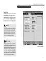
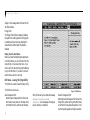
1
Copyright
Fujitsu PC Corporation has made every eVort to ensure
the accuracy and completeness of this document.
However, as ongoing development eVorts are continually improving the capabilities of our products, we
cannot guarantee the accuracy of the contents of this
document. We disclaim liability for errors, omissions,
or future changes.
LifeBook is a trademark of Fujitsu PC Corporation.
The following are registered trademarks of IBM
Corporation:IBM,IBM PC AT, IBM PS/2.
The following are registered trademarks of Microsoft
Corporation:MS,MS-DOS, Windows NT, Microsoft
Windows for Workgroups, Windows 95.
PCMCIA is a trademark of the Personal Computer
Memory Card International Association.
Phoenix and the Phoenix logo are registered
trademarks of Phoenix Technologies,Ltd.
Intel Pentium is a trademark of Intel Corporation.
All Kensington Corporation products are registered
trademarks of Kensington Microware Limited.
PC-Doctor is a trademark of watergate.software.inc.
SoftPEG™ is a registered trademark of CompuCore
Multimedia Inc.
LapLink is registered trademark of Traveling Software Inc.
All other products are trademarks or registered
trademarks of their respective companies.
© Copyright 1996 Fujitsu PC Corporation. All rights
reserved. No part of this publication may be copied,
reproduced, or translated, without prior written
consent of Fujitsu PC Corporation. No part of this
publication may be stored or transmitted in any
electronic form without the written consent of
Fujitsu PC Corporation.
D E C LA RATION OF CONFORMITY
according to FCC Part 15
Responsible Party Name: Fujitsu PC Corporatio
Address: 598 Gibraltar Drive
Milpitas,CA 95035
Telephone: (408) 935-8800
Declares that product: Model:LifeBook 420D
Complies with Part 15
of the FCC Rules.
This device complies with Part 15 of the FCC r
Operations is subject to the following two condit
(1) This device must not be allowed to cause har
interference, (2) This device must accept any inte
ence received, including interference that may c
undesired operation.
David Woo
full name
Fujitsu
company
2/18/97
date
Consult the dealer or an exp erienced radio/TV
technician for help.
Shielded interconnect cables must be employed with
this equipment to ensure compliance with the pertinent RF emission limits governing this device.
■
CAUTION
Changes or modification not expressly approved
by Fujitsu PC Corporation could void this user’s
authority to operate the equipment.
FCC Notices
Notice to Users of Radios and Television
These limits are designed to provide reasonable protection against harmful interference in a residential installation. This equipment generates,uses, and can radiate
radio frequency energy and, if not installed and used
in accordance with the instructi on s ,m ay cause harmful
interference to radio communications. However, there
is no guarantee that interference will not occur in a
particular installation. If this equipment does cause
harmful interference to radio or television reception,
which can be determined by turning the equipment
oV and on, the user is encouraged to try to correct the
interference by one or more of the following measures:
■
■
■
Reorient or relocate the receiving antenna.
Increase the separation between the equipment and
receiver.
Connect the equipment into an outlet that is on
a diVerent circuit than the receiver.
If you experience trouble with this equipment please
contact your support representative, toll free at 1-8008FUJITSU (1-800-838-5487) or Fujitsu Computer
Products of America (FCPA),7300 NE Evergreen
Parkway, Hillsboro, OR 97124, telephone
503-681-7300.
DOC (Industry Canada) Notices
Notice to Users of Radios and Television
This Class B digital apparatus meets all requirements
of the Canadian Interference-Causing Equipment
Regulations.
CET appareil numérique de la class B respecte toutes
les exigence du Réglement sur le matérial brouilleur
du Canada.
UL Notice(For Authorized Repair Technicians Only)
CAUTION: For continued protection against risk of fire, replace only
with the same type and rating fuse.
CAUTION:Danger of explosion if CMOS battery is incorrectly
replaced. Replace only with the same or equivalent type recommended
by the manufacturer. Dispose of used batteries according to the
manufacturer’s instruction.
WARNING: CMOS Battery may explode if mistreated. Do not recharge,
disassemble or dispose of in fire.
Table of C ontents
T a b l e
Preface
o f
C o n t e n t s
. . . . . . . . . . . . . . . . . . . vi
Section One
Setting Up Your LifeBook 400 Series
Unpacking. . . . . . . . . . . . . . . . . . . . 2
Overview of Features . . . . . . . . . . . . . . 3
Component Identification . . . . . . . . . . . 4
Power Sources. . . . . . . . . . . . . . . . . . 9
Data Security . . . . . . . . . . . . . . . . . . 9
Starting Your Computer for the First Time . 10
User Registration . . . . . . . . . . . . . . . 13
Learning About Your Operating System
and Application Software. . . . . . . . . . 14
Section Two
Configuring Your LifeBook 400 Series
Using your LifeBook 400 Series
from Fujitsu . . . . . . . . . . . . . . . . 16
Status Indicator Panel . . . . . . . . . . . . . 17
Identifying the Drives . . . . . . . . . . . . . 44
Power Center by Fujitsu. . . . . . . . . . . . 20
Power On . . . . . . . . . . . . . . . . . . . 21
Special Operating System Features . . . 22
Power OV . . . . . . . . . . . . . . . . . . . 23
Restarting the System . . . . . . . . . . . . . 24
Batteries . . . . . . . . . . . . . . . . . . . . 25
Integrated TouchPad Pointing Device . . . . 27
Using the Keyboard . . . . . . . . . . . . . . 29
Floppy Disk Drive . . . . . . . . . . . . . . . 31
CD-ROM Drive . . . . . . . . . . . . . . . . 33
ii
Section Three
Using Your LifeBook 400 Series
Boot Sequence . . . . . . . . . . . . . . . . . 44
BIOS Setup Utility. . . . . . . . . . . . . . . 45
Navigating Through the Setup Utility . . . . 46
Main Menu – Setting System Parameters . . 48
Exiting from the Main Menu . . . . . . . . . 57
Advanced Menu – Setting Device Controls . 57
Exiting from the Advanced Menu . . . . . . 64
Security Menu . . . . . . . . . . . . . . . . . 65
Exiting from the Security Menu . . . . . . . 67
Power Savings Menu . . . . . . . . . . . . . 67
Exiting from the Power Savings Menu . . . . 69
Hard Drive . . . . . . . . . . . . . . . . . . . 35
Boot Menu – Selecting the
Operating System Source . . . . . . . . . 71
Power-Saving Modes . . . . . . . . . . . . . 36
Exiting from the Boot Menu . . . . . . . . . 72
Video and Audio Functions . . . . . . . . . . 40
Exit Menu – Leaving the Setup Utility . . . . 72
File Transfers. . . . . . . . . . . . . . . . . . 41
Setting Up Your Save-To-Disk
File Allocation . . . . . . . . . . . . . . . 73
LifeBook 4 00 Series from Fuj
Tab l e
Section Four
o f
C o n t en ts
Section Five
Appendices
User Installable Features
Troubleshooting
RAM Module . . . . . . . . . . . . . . . . . 76
Identifying the Problem . . . . . . . . . . . . 90
Warranty . . . . . . . . . . . . . . . . . . .
PCMCIA Cards . . . . . . . . . . . . . . . . 79
Specific Problems . . . . . . . . . . . . . . . 91
LifeBook 420D Specifications . . . . . . . .
Installing a Theft Prevention Lock . . . . . . 82
Power On Self Test Messages . . . . . . . . 110
Approvals . . . . . . . . . . . . . . . . . . .
Optional External Installation of
Floppy Disk Drive . . . . . . . . . . . . . 82
Emergency CD-ROM Tray Release . . . . . 113
Accessories . . . . . . . . . . . . . . . . . .
Installing and Removing the
Internal Hard Drive . . . . . . . . . . . . 113
Appendix B Glossary. . . . . . . . . . . . .
Restoring Your Pre-installed Software
from CD-ROM . . . . . . . . . . . . . . 114
Index .
Nickel Metal Hydride Battery Pack . . . . . . 83
Multi-function Bay . . . . . . . . . . . . . . 84
CD-ROM Drive . . . . . . . . . . . . . . . . 85
Removable Floppy Disk Drive . . . . . . . . 86
Installing Devices on the LPT Port . . . . . . 86
Section Six
Installing Devices on the COM Port . . . . . 86
Care and Maintenance
Installing External Monitors . . . . . . . . . 86
Care and Maintenance . . . . . . . . . . . . 116
Installing a Mouse or Keyboard . . . . . . . 86
Caring for Your Notebook . . . . . . . . . . 116
Installing a Replicator Port or
Mini-Docking Station . . . . . . . . . . . 86
Increasing Battery Life . . . . . . . . . . . . 116
Installing Audio Input Devices . . . . . . . . 87
Installing Audio Output Devices . . . . . . . 87
Appendix A Specifications . . . . . . . . . .
. . . . . . . . . . . . . . . . . . .
P r e f a c e
Preface
The LifeBook 400 Series from Fujitsu PC
Corporation is a powerful notebook computer.
It is powered by an Intel Pentium microprocessor, has a built-in color display, a CD-ROM
drive and brings the computing power of
desktop personal computers (PCs) to a
portable environment.
This manual explains how to operate your
LifeBook 400 Series’ hardware and built-in
system software. The LifeBook 400 Series is
compatible with the IBM PC AT.® Depending
on your model,it comes with Windows® 95,
Windows for Workgroups™ Version 3.11 and
MS-DOS Version 6.22 or only Windows 95
pre-installed. When you first start your notebook, you will be asked to select a single
operating system if both are present.
(See pages 11-13 for more information
on selecting your operating system.)
vi
Your LifeBook 400 Series is a completely selfcontained unit with a passive-matrix (DSTN)
color LCD display. It has a powerful interface
that enables it to support a variety of optional
features.(Figure P-1.)
CAUTION
When you first turn on your LifeBook
400 Series the Windows 95 Setup screen
will appear. This is true even if you will
be using Windows for Workgroups.
L if e B o ok 4 0 0 S e r ie s f r om F uj
LifeBook 400 Series from Fujitsu
Figure P-1 LifeBook 400 Se
with both Fujitsu
Third Party Opt
P r e f a c e
Conventions Used in the Guide
In this manual, figures which show screens are
intended as examples only, and screen and file
names may diVer in actual use.
Messages displayed by your LifeBook 400 Series
appear in Courier type.
Example: Starting MS-DOS
Commands that you enter into your notebook
using the keyboard appear in Courier type.
Example: C:>DIR/P
Keyboard keys are shown in boldface
Helvetica type.
Example: Fn, F1, Esc, and Ctrl.
Pages with additional information about a specific topic are cross-referenced within the text.
Example: (See page xx.)
viii
POINT
The point icon highlights information
that will enhance your understanding of
the subject material.
CAUTION
The caution icon highlights information
that is important to your safety, to the
safe operation of your notebook, or to
the integrity of your files. Please read all
caution information carefully.
S e c t i o n
S e t ti n g U p Yo u r Li fe B o o k 4 0 0 Ser i e s
Unpacking . . . . . . . . . . . . . . . . . . . 2
Overview of Features . . . . . . . . . . . . . 3
Component Identification . . . . . . . . . . . 4
Power Sources . . . . . . . . . . . . . . . . . 9
Data Security. . . . . . . . . . . . . . . . . . 9
Starting Your Notebook for the First Time . . 10
User Registration . . . . . . . . . . . . . . . 13
Learning About Your Operating System
and Application Software . . . . . . . . . . . 14
S e c t i o n
O n e
Section ONE
■
■
Setting Up Your LifeBook 400
Series from Fujitsu
This section describes how to set up your
LifeBook 400 Series from Fujitsu. We strongly
recommend that you read it before using your
notebook – even if you are already familiar with
notebook computers.
■
■
User’s Guide.
Registration card and customer
information pack.
Microsoft Windows 95 Manual.
Additional equipment and documentation
depending on the option package you
have purchased.
Figure 1-2 AC Adapter Unit
Unpacking
When you receive your notebook,unpack it
carefully, and compare the parts you have
received with the items listed below.
For a standard configuration you should have:
■
■
■
■
2
LifeBook 400 Series from Fujitsu.(Figure 1-1.)
AC Adapter with AC power cord (located in
the accessories box).(Figure 1-2.)
Figure 1-3 Floppy Disk Drive
Modular 10-speed CD-ROM Drive (already
installed in your notebook).
Modular 3.5" Floppy Disk Drive (located in
the accessories box).(Figure 1-3.)
Figure 1-1 LifeBook 400 Series Notebook
LifeBook 4 00 Series from Fuj
Se t t i n g U p Yo u r L i fe B oo k 40 0 Se r i e s
Once you have checked and confirmed that
your notebook system is complete, connect
the AC Adapter and follow the instructions on
page 9 to accept the conditions for using the
LifeBook 400 Series and for selecting the operating system you will use. When you have completed that setup process please complete and
send in your registration card.
Overview of LifeBook 400
Series Features
The LifeBook 400 Series is a compact, yet
powerful notebook computer available with
standard features including:
(See Appendix A, pages 120–123, for detailed
information.)
■
■
■
■
120 MHz Intel Pentium™ processor.
8MB EDO RAM standard, expandable to
72MB.
11.3" passive-matrix (DSTN) color display
with 800 x 600 resolution.
1MB Video RAM.
■
■
Built-in 1.0GB hard drive.
■
Multi-function bay which supports
warm swapping of the following:
■
■
■
3.5" floppy disk drive (included with
all models).
10-speed CD-ROM drive (included with
all models).
■
Nickel Metal Hydride (NiMH) Battery Pack.
■
16-bit Sound Blaster™-compatible sound chip.
■
Zoom Video port for full motion video
acceleration.
■
Built-in stereo speakers.
■
Two Type II or one Type III PCMCIA slot.
■
■
■
IrDA 1.0 compatible infrared port for wireless data transfer.
Integrated TouchPad Pointing Device for easy
cursor control.
External monitor support.
Full size keyboard with three dedicated
Windows 95 keys.
Hot swap connection for an external
keyboard or an external mouse.
■
Stereo line input jack.
■
Stereo headphone/speaker jack.
■
Standard Pre-installed software:
■
■
■
■
■
Operating System.
LapLink 7.0 for file transfers via modem
cable or infrared port.
PC Doctor for system diagnostics.
SoftPEG from CompCore,a MPEG-1
video player.
Some models may include additional
software.
S e c t i o n
O n e
Component Identification
For detailed specifications refer to Appendix A
on pages 120–123.
Display Panel Latch
This latch locks and releases the display panel.
LCD Display Panel
This is a color LCD panel with back lighting for
the display of text and graphics.
Suspend/Resume Button
The Suspend/Resume Button allows you to
suspend computer activity without turning oV
your notebook power, and to return it to an
active state. This feature saves power, and is
particularly useful when your notebook is
running only on battery power. (See pages
20–21, 36–40,and 67–69 for more information
on Power Management.)
Brightness Control
The brightness control adjusts the overall intensity of the display screen back lighting.
Contrast Control
The contrast control adjusts the contrast of the
display screen. It is located just below the
brightness control.
Status Indicator Display
LCD display of the status of the power state and
source, Suspend Mode, battery charge, floppy
disk drive activity, hard drive activity, CD-ROM
drive activity, PCMCIA card activity, Caps
Lock, Num Lock and Scroll Lock.
Display Latch
Figure 1-4 Top and Front Panel
4
LifeBook 4 00 Series from Fuj
Se t t i n g U p Yo u r L i fe B oo k 40 0 Se r i e s
Display Latch
LCD Display
Status Indicator Display
Stereo Speaker
Brightness Control
Keyboard
Contrast Control
Keyboard Removal Tab
Suspend/Resume Button
Closed Cover Switch
Stereo Speaker
TouchPad Pointing Device
Multi-function Bay
Keyboard Removal Tab
Figure 1-5 LifeBook 400 Series with Display O
S e c t i o n
O n e
CAUTION
Be sure you know what settings are
active for your Suspend/Resume Button
before you use it because misuse can
result in data loss. (See the Power
Savings Menu of the BIOS Setup Utility
on page 68 for more information.)
the front of the keyboard in place.Lifting the
tabs is only necessary to access the Memory
Expansion Chamber which is under the keyboard. (See pages 76–79 for more information.)
CAUTION
Do not attempt to install or remove a
RAM Module if your notebook has been
recently used. The surface area under
the keyboard can be very hot and may
injure you.
Closed Cover Switch
This switch turns oV the LCD back lighting
when the display panel is closed,thus saving
power.
Speakers
The built-in dual speakers output stereo sound
from your notebook.
Keyboard
A full size keyboard with dedicated Windows 95
keys for input into your notebook.
Keyboard Removal Tabs
A pair of tabs which cover screws which hold
6
TouchPad Pointing Device
A touch sensitive cursor control system with
two click buttons.
Multi-function Bay
This bay accommodates:
■
10-speed CD-ROM drive.
■
3.5" floppy disk drive.
PCMCIA
Card Slot
Lock
Eject
Buttons
Optional External
Floppy Disk Drive
Adapter Connector
Built in
Microphone
Battery Eject Button
Figure 1-6 LifeBook 400 Series Left Side Panel
PCMCIA Card Slot, with Cover,
Lock and Eject Button
The PCMCIA Card Slot allows you to install
two type I or II PCMCIA cards or one type III
PCMCIA card.(See pages 79–81 for more
information on PCMCIA cards.) The button to
the left of the card slot locks the card in place,
and the buttons to the right of the slot ejects
the card(s) from the slot.
External Floppy Disk Drive Adapter Connector
A connector for attaching an optional external
floppy disk drive adapter. The adapter allows
you to use your modular floppy disk drive when
the multi-function bay is being used for another
purpose.
LifeBook 4 00 Series from Fuj
Se t t i n g U p Yo u r L i fe B oo k 40 0 Se r i e s
Main Battery Eject Button
This releases the Removable Main Nickel
Metal Hydride Battery Pack for removal
and installation.
Power Switch
This switch is the main power switch for
your notebook.
PS/2 Connector
The connector allows you to connect an ext
nal PS/2 keyboard, mouse, or numeric keypa
Built-in Microphone
The built-in microphone allows mono audio
input to your notebook.
Volume
Control
DC Power Input Connector
The DC Power Input Connector allows you t
plug in the Fujitsu AC Adapter or the option
Fujitsu Auto Adapter.
Headphone
Jack
Power Switch
DC Power
Input Connector
Volume Control
This knob provides hardware control of sound
level of audio outputs from your notebook.
Audio Input Jack
The Audio Input Jack allows you to connect an
external audio source to your notebook,like an
audio cassette player. This jack will not support
an external microphone.
Headphone Jack
You can install headphones or powered external
speakers in the Headphone Jack.
Multi-function Bay Release Button
This is the release to allow removal and installation of devices in the Multi-function Bay.
Theft Prevention Lock Slot
This is a slot that allows you to attach a phy
lock down device.
Audio
Input
Jack
Multi-function Bay
Release Button
PS/2
Connector
Theft
Prevention
Lock Slot
Figure 1-7 LifeBook 400 Series Right Side Panel
CAUTION
There are software volume controls.
The knob setting and the software settings will interact. Software volume
Off will override the knob setting.
(See Volume Control on page 41 for
more information.)
Serial Interface Connector (COM Port)
The Serial Interface Connector allows you to
connect serial RS-232C devices, such as a se
printer or a serial scanner.
Expansion Bus Connector
This connector is for connection to an optio
port replicator or docking station. The conne
tor cover must be closed and the sliding pane
opened to reveal only the Expansion Bus
Connector when connecting a port replicato
or docking station.
S e c t i o n
O n e
Parallel Interface Connector (LPT Port)
The Parallel Interface Connector allows you
to connect parallel devices, such as a parallel
printer to your notebook.
Tilt Adjustment Foot
COM Port
LPT Port
Configuration
Label
External SVGA or Hi Res Monitor Connector
This connector allows you to connect an external VGA or SVGA CRT or Hi-Res monitor.
Infrared IrDA Compatible Communication Port
The IrDA compatible Communication Port
allows you to communicate with another IrDA
compatible device without a cable. (See page 41
for more information.)
Tilt Adjustment Feet
These are a pair of feet which flip down and
hold the back of the keyboard approximately
6° higher than the front when resting on a flat
surface. They are designed to make using your
notebook keyboard more comfortable.
Main Unit Label
This label has the model number, serial number
and other information about your notebook.
8
Tilt Adjustment Foot
Expansion Bus Connector
Main
Unit
Label
Internal
Hard Drive
Chamber
Monitor Connector
Multi-function Bay
Infrared Port
Battery Chamber
Figure 1-8 LifeBook 400 Series Back
Figure 1-9 LifeBook 400 Series Bottom
CAUTION
The cover which closes over the connectors on the rear of your notebook can be
damaged if it is left open when your
notebook is moved around.
Configuration Label
This label has manufacturer information that
you will need to give your support representative so that he or she can help you. It exactly
identifies the version of various component
parts of your notebook.
LifeBook 4 00 Series from Fuj
Se t t i n g U p Yo u r L i fe B oo k 40 0 Se r i e s
Internal Hard Drive Chamber
This chamber houses the internal hard drive.
It should only be accessed for maintenance
by an authorized maintenance provider.
Power Sources
Data Security
Your notebook has three possible power
sources: the Nickel Metal Hydride Battery Pack,
the AC Adapter, or the optional Auto Adapter.
Battery Chamber
This chamber houses the Nickel Metal Hydride
Battery Pack or the optional Lithium ion
Battery Pack.
Connecting the Power Adapters
The AC Adapter or the Auto Adapter provides
power for operating your notebook and charging the battery pack.(Figure 1-10.)
Your LifeBook 400 Series has a built-in hardw
control password security feature that allows
to protect the data stored in your notebook f
unauthorized access. Your operating system a
some applications have software control pass
word security features that allows you to prot
all or portions of the data stored in your note
book from unauthorized access.
To Connect the AC Adapter
CAUTION
The Nickel Metal Hydride Battery Pack is
not charged when you purchase your notebook. Initially you will need to connect the
AC Adapter or the Auto Adapter to use it.
It can take up to 3 hours to charge a
Battery Pack if your notebook is Off or in
Suspend Mode. If your notebook is in use,
it can take up to 9 hours or more to charge
a Battery Pack.
1.Plug the DC output cable of the AC Adapter
into the DC Power Input Connector on the
right side panel of your notebook.
2.Plug the AC Adapter into an AC
electrical outlet.
To Connect the Optional Auto Adapter
1.Plug the DC output cable into the DC Power
Input Connector on the right side panel of
your notebook.
2. Plug the Auto Connector into the cigarette
lighter of a car or other vehicle with the ignition key in the On or the Accessories position.
Hardware Data Security Features
When you are using your notebook built-in
hardware control password to gain access
to your notebook the actual password will
not appear on the screen. This is a safety
precaution. The hardware control security
parameters are set from the BIOS Setup Utili
(See Security Menu on pages 65–67 for more
information on setting and clearing passwords
and enabling and disabling built-in
security features.)
S e c t i o n
O n e
Software Data Security Features
The operating system and some applications
have security features that are independent of
the built-in hardware protection features that
are controlled from the BIOS. See your software
documentation for more information about
these features.
CAUTION
Software security feature passwords may
not be the same as the hardware security
passwords. Be sure you know which features are controlled from software and
which from hardware or you may lock
yourself out of your own data or lock
up your hardware and not be able to
operate your notebook.
CAUTION
Make sure you memorize your passwords, both hardware and software. If
you forget, you may not be able to use
your notebook, and you will have to
contact your service provider and arrange
to have them reset the hardware system
password. See your software manuals for
what to do if you forget your software
security password(s).
10
Starting Your Notebook for
the First Time
Booting the System
The first time that you turn on your notebook
you will need to attach your AC Adapter as the
battery is not charged when it arrives. We
strongly recommend that you do not attach any
other external devices and do not put any CD
or floppy disk in the drives until you have gone
through the initial power on sequence.
When you turn on your notebook for the first
time it will p erform a power on self test and
display some status information on the screen
with a message
Press <F2> for Setup
,
if you do nothing the system will read the hard
drive for the operating system software and
the Windows 95 Setup Screen will appear.
(See Power On on pages 21–22 for additional
help.) You will then be stepped through the
condition of use and operating system selection
process. You must complete this initial process
before you will be able to use your notebook.
CAUTION
If you have purchased a system which
allows you to use a choice of operating
systems, the Operating System selection
can only be made once. You cannot
change your mind, the option will never
be available again.
LifeBook 4 00 Series from Fuj
Se t t i n g U p Yo u r L i fe B oo k 40 0 Se r i e s
Conditions of Use
The first time you start your notebook you must
confirm your acceptance of the copyright limitations for your pre-installed software. If you
have purchased a unit which allows you to
use a choice of operating systems you must
choose between Windows 95 and Windows for
Workgroups. Once you have chosen your operating system you cannot change your mind, the
other system will not be available to you.Please
decide carefully. After your notebook completes
the installation of the operating system it will
not ask you again for confirmation of the conditions of use nor to choose an operating system.
CAUTION
When you first turn on your notebook
the Windows 95 Setup screen will
appear. This is true even if you will be
using Windows for Workgroups.
Every LifeBook 400 Series Model has 10 screens
to read carefully and/or answer questions by
typing in information. If your notebook has a
choice to use Windows for Workgroups there
will be three additional screens. All of the
screens are Windows 95 Setup screens.
You cannot use your notebook until this setup
process is completed. The bottom of each
screen has a <Back Button, a Next> Button
and a Cancel Button which are activated by
the Integrated Touchpad Pointing Device cursor
control and button click. The <Back Button
will return you to the previous screen. The
Next> Button activates any choices or information you have entered and takes you on to the
next screen. The Cancel Button allows you to
stop the setup process. If you stop the process
your notebook will come back to the place in
the Windows 95 Setup where you left oV the
next time you start your machine. The screens
you will be required to respond to are shown
with the required action.
Welcome to Windows Setup
Read and then click on the Next> Button.
Regional Settings
Select language, number format, date format
etc. for the operating system to use by movin
cursor up and down the list to the desired
world region shown in the table and then clic
on the Next> Button. Use the up arrow Õ
down arrow Ô keys to move down up and
down the text one line at a time.
Keyboard Layout
Select the keyboard language and format you
wish to use by moving cursor up and down t
list to the desired selection shown in the tab
and then click on the Next> Button. You can
scroll through the text using the up arrow Õ
and down arrow Ô keys to move down up an
down the text one line at a time.
User Information – Software Licensing
Fill in your name and your company name a
you would like to see it on the software licens
and then click on the Next> Button. You m
make an entry in order to continue.
S e c t i o n
O n e
POINT
If your system comes with Windows 95
only, you will find a Recovery CD-ROM
packet in your accessories box. Please
store the packet in a safe place in case
there is a loss of data. (See Restoring
Your Pre-installed Software from CDROM on page 114.)
License of Windows 95
Read carefully and then click on the Next>
Button.
License Agreement
Read the agreement carefully. You can scroll
through the text using the Integrated TouchPad
Pointing Device to activate the scroll bar or use
the up arrow Õ and down arrow Ô keys to
move up and down the text one line at a time.
When you finish reading simply point and click
to accept or reject the terms of the agreement
and then click on the Next> Button.
12
POINT
If you reject the terms of the license
agreement the operating system setup will
abort and shutdown your notebook.
When you turn on the system the next
time, it will begin the Setup process again.
Certificate of Authenticity
Look in the box that your notebook came in and
you will find a Windows 95 Certificate of
Authenticity and a Windows 95 Users manu a l .O n
the certificate and also on the back of the manual
you will find a bar-code with a number above it.
These numbers should be the same. They are your
product code and the number you should enter
on the Certificate of Authenticity screen. When
you have entered the number exactly as shown
then click on the Next> Button.
CAUTION
If your system came with a choice of operating systems, you will need to make back
up disks. (See Create System Disks page
13.)
*Windows Version
To select Windows for Workgroups point and
click on the Change Button. To select Windows
95 point and click on the Next> Button.
(If you select Windows 95 you will go directly
to the Configuring the Computer Screen.)
*Operating System Choice
To select Windows for Workgroups point and
click on the Windows for Workgroups selection
and then point and click on the Next> Button.
To select Windows 95 point and click on the
Windows 95 selection and then point and click
on the Next> Button.
Configuring the Computer
If you have a unit with only Windows 95 or
have selected Windows 95 this screen will
appear when Windows 95 is ready to install.
(If you purchased a LifeBook 400 Series which
only comes with Windows 95 this screen will
appear immediately after the Certificate of
Authenticity Screen.) You may be prompted for
time zone and printer. You do not need to select
a printer at this time.
LifeBook 4 00 Series from Fuj
Se t t i n g U p Yo u r L i fe B oo k 40 0 Se r i e s
Installing Devices
This screen will appear while your notebook
loads the operating system and when it finishes
it will automatically go to the next screen.
CAUTION
If you have chosen Windows for
Workgroups please fill out the fulfillment
coupon that came in the box with your
notebook and send it, and the Windows
95 manual, to the address provided.
When the coupon and manual are
received, you will be sent a set of
Windows for Workgroups backup disks
and manual.
*Create System Disks
If your system came with a choice of operating
systems, you will be prompted to create system
disks. We strongly recommend that you make a
system backup so you can restore your factory
installed software in case of data loss. If you
have chosen Windows 95 you will need to backup your operating system and your factory
installed applications and drivers. The backup
will require 40 floppy disks. If you have chosen
Windows for Workgroups you only need to
backup the factory installed applications and
drivers. The backup will require 9 floppy disks.
Finishing Setup
Click on the Finish Button and your notebook
will restart with the selected Windows operating system ready for normal operation.
POINT
If you do not have enough floppy disks
available during the setup process you
can create system backup disks at any
time. From the Start Menu, select
Accessories, then System Tools, then
Create System Disks.
User Registration
There are three ways to register your notebo
1. Mail-in Registration – Fill in the registrat
card provided in the box with your LifeBo
400 Series and mail it to Fujitsu.
2.On-line Electronic Registration – Fill out t
registration form behind the Fujitsu Icon o
your Desktop and send it by e-mail.
3. Internet Registration – Use the registratio
utility on the Fujitsu PC Service and Supp
Web Site at www.8fujitsu.com to register y
notebook.
S e c t i o n
O n e
Learning About Your Operating System
and Application Software
Tutorials
All operating systems and most application
software have tutorials built-in. We highly
recommend that you step through the tutorial
before you use an application, even if you
are familiar with the same application on a
diVerent machine, an earlier version of the
application, or with a similar product.
Manuals
In the accessories box you will find manuals for
Windows 95 and other pre-installed software.
Some software manuals are available on-line
and are not in the box. See the help screens of
your software. We recommend that you review
these manuals for general information on the
use of these applications and to get a basic
understanding of what is covered in the manual,and how it is organized,should questions
arise as you use the applications.
14
S e c t i o n
Using Your LifeBook 400 Series from Fujitsu
Using Your LifeBook 400 Series from Fujitsu . 16
Status Indicator Panel. . . . . . . . . . . . . 17
Power Center by Fujitsu . . . . . . . . . . . 20
Power On . . . . . . . . . . . . . . . . . . 21
Special Operating System Features . . . . . . 22
Power Off . . . . . . . . . . . . . . . . . . 23
Restarting the System . . . . . . . . . . . . 24
Battery . . . . . . . . . . . . . . . . . . . . 25
Integrated TouchPad Pointing Device. . . . . 27
Using the Keyboard. . . . . . . . . . . . . . 29
Floppy Disk Drive . . . . . . . . . . . . . . . 31
CD-ROM Drive . . . . . . . . . . . . . . . . 33
Hard Drive . . . . . . . . . . . . . . . . . . 35
Power-Saving Modes . . . . . . . . . . . . . 36
Video and Audio Functions . . . . . . . . . . 40
File Transfers . . . . . . . . . . . . . . . . . 41
T w o
S e c t i o n
T w o
Section TWO
Using Your LifeBook
400 Series from Fujitsu
This section describes the indicators, buttons,
connections and operating modes of your
LifeBook 400 Series and their use.
Opening the Unit
Lifting the latch releases the cover and allows
your notebook to be opened.Lift the display
backward until the screen is at a comfortable
viewing angle. (Figure 2-1.)
Adjusting the Built-in Display
When you turn on your notebook, you may want
to adjust the brightness level of the screen for best
visibility. To do this, adjust the brightness slider on
the right side of the built-in display screen. You
may need to adjust the brightness periodically
for different operating environments. You will
probably want to adjust the contrast as well as
the brightness. To do this, use the contrast slider
on the right side of the built-in display screen
just below the brightness control. (Figure 2-2.)
16
Brighter
Less Bright
Figure 2-1 Opening the LCD Display
POINT
The higher the level of brightness, the
more power your notebook will consume,
and the faster the battery will discharge.
Adjusting the Keyboard Angle
On the bottom of your notebook,near the
back,are a pair of feet which flip down and
hold the back of the keyboard about 6° higher
than the front when resting on a flat surfa ce.
More Contrast
Less Contrast
Figure 2-2 Display Adjustments
They are designed to make using your notebook more comfortable when using the keyboard. The feet must be folded flat against the
bottom of your notebook when opening or
using a CD-ROM or it will not open or operate
properly. (Figure 1-9 on page 8.)
LifeBo ok 400 Series from Fuji tsu
Using
Your
LifeBook
400
Series
CAUTION
Do not operate the CD-ROM drive or
attempt to open the tray unless your
notebook is sitting on a flat surface and
the adjustment feet are folded against the
bottom of your notebook. Using a CDROM drive when it is not level may damage the drive or prevent proper operation.
CAUTION
When you are not using the adjustment
feet be sure that they are folded flat
against the bottom of your notebook.
They could be broken off, or injure
someone, if not used properly.
Status Indicator Panel
The Status Indicator LCD Display Panel is
located in the recess just above the keyboard.
(Figure 2-3.) The appropriate indicators
become visible when you use your notebook.
Power
Battery
Charging
AC
Adapter Inidcator
Battery
Level
Battery
Identifier
Unused CD-ROM
Floppy
NumLock
Scroll Lock
Drive
Disk
Indicator
PCMCIA Indicator
Access
Drive
Card Access
CAP Lock
Indicator
Access
Indicators
Indicator
Hard Indicator
Drive
PCMCIA
Access
Card
Indicator
Identifier
Figure 2-3 Status Indicators
17
S e c t i o n
T w o
Power Indicator
The Power Indicator tells you when the system is
operational. It is on steady when there is power
to your notebook, and blinks when the system
is in Suspend Mode. It goes off when the system
has entered Save-to-Disk Mode, has entered the
Windows 95 shutdown inactivity state, or the
power is turned off from the Power Switch.
POINT
When your notebook has been shutdown from Windows 95, it is the same
as turned off from the Power Switch
except that it can be turned on by pressing the Suspend/Resume Button. It is not
drawing current in this state.
AC Adapter Indicator
The AC Adapter Indicator tells you whether the
system is operating on the AC or Auto Adapter,
or running on battery alone. The indicator is On
18
when either of the adapters is active and Off
when power comes from the battery alone. If a
battery is charging the power adapter is active
regardless of the setting of the Power Switch.
The AC Adapter is also active in the Windows
shutdown state, regardless of the battery status.
If there is no battery charging, and the Power
Switch is Off, then the AC Adapter Indicator and
the Battery Condition Indicator will all be Off.
Battery Condition Indicator
This indicator shows whether or not the Nickel
Metal Hydride Battery Pack is installed and
indicates the condition.(Figure 2-3.) Battery 0 is
the Nickel Metal Hydride Battery Pack. The
Battery Status Indicator is displayed only if the
battery is install ed .( Ba t tery 1 display will flash
when you power up but will never be displayed.)
A small arrow icon appears to the left of the battery symbol and above the number if the battery
is charging. The charging indicator flashes if the
battery is too hot or too cold to charge. The
charging indicator operates whether the Power
Switch is Off or On. The symbols inside the bat-
tery outline indicate the operating level available
for the battery. (Figure 2-4.) If there is no battery charging and the Power Switch is Off then
the AC Adapter Indicator and the Battery
Condition Indicator will all be Off.
76–100%
51–75%
26–50%
13–25%
Low Battery ≤12%
Dead Battery
Shorted Battery
Figure 2-4 Battery Condition Indicator
LifeBo ok 400 Series from Fuji tsu
Using
CAUTION
Turning off the power with the Power
Switch or using the Suspend/Resume
Button when any of the Access Indicators
are On may cause loss of data and/or
system errors.
CD-ROM Drive Access Indicator
The CD-ROM Access Indicator tells you a
CD-ROM is being accessed.
Your
LifeBook
400
Series
POINT
If you do not wish to have the CD automatic insertion function you can disable it.
When using Windows 95, the CD-ROM
automatic insertion function periodically
checks for a CD installed in the drive,
causing the access indicator to flash. The
CD automatic insertion function allows the
system to automatically start a CD application as soon as a CD is inserted in the
drive and the tray is closed. It will begin
playing an audio CD or will start an application if the CD has an auto run file on it.
8. Click on MATSUSHITA UJDCD6710.
In order to disable the CD automatic insertion
function proceed as follows:
9. Click on Properties. The MATSUSHITA
UJDCD6710 Properties dialogue box will
be displayed.
1. Save all data and close all applications.
10. Click on the Settings tab.
2. Click on the Start Button.
11. Click on the automatic insertion box to
toggle it Off.
3. Point to Settings.
POINT
7. Click on the + to the left of the CD-ROM
icon.MATSUSHITA UJDCD6710 will be
displayed.
4. Click on the Control Panel. The Control
Panel window will be displayed.
5. Double click on the System icon. The System
Properties dialogue box will be displayed.
6. Click on the Device Manager tab. The device
list will be displayed.
12. Click on OK.
13. Click on OK in the System Properties
dialogue box.
14. Restart your notebook according to the
message displayed.
You can re-enable the function by repeating the
process except in step 11 change the setting to On.
19
S e c t i o n
T w o
CAUTION
If you switch off power using the Power
Switch or operate the Suspend/Resume
Button while any of the access indicators
are on, you may cause data to be lost
and/or a system error to occur.
Hard Drive Access Indicator
The Hard Drive Access Indicator tells you when
the internal hard disk is being accessed.
Floppy Disk Drive Access Indicator
The Floppy Disk Drive Access Indicator tells
you a floppy disk is being accessed.
PCMCIA Card Access Indicators
The PCMCIA Card Access Indicator tells you
an installed PCMCIA card is b eing accessed.
Card 0 is the bottom connector and Card 1 is
the upper connector in the card slot. Type III
cards are always Card 0 only.
20
POINT
Windows 95 displays of PCMCIA slot
numbers may be different than the
Status Indicator slot numbers.
NumLock Indicator
The NumLock Indicator tells you the internal
keyboard is set in ten-key numeric mode. (See
pages 29–30 for more information on the numeric
keypad.) You can activate the NumLock Mode
by pressing the Scr Lk/Num Lk key while holding down the Shift key. Deactivate the mode the
same way that you activated it. This indicator is
inactive if you are using an external keyboard.
CapsLock Indicator
The CapsLock Indicator tells you when the keyboard is set for all capital letters. Activate the
Caps Lock Mode by pressing the CapsLock key
on the keyboard. Deactivate the mode the same
way that you activated it. This indicator is inactive if you are using an external keyboard.
ScrollLock Indicator
The ScrollLock Indicator tells you when you are
in Scroll Lock Mode. You can activate or deactivate the scroll lock mode by pressing the Scr
Lk/Num Lk key. Deactivate the mode the same
way that you activated it. This indicator is inactive if you are using an external keyboard.
Power Center by Fujitsu
Your notebook desktop has multiple power
items. There is a Power Bar which automatically
displays the charge condition of the battery and
a set of control icons as the pointer moves
along near it. There is a power icon in the task
bar in the lower right of the display. There is a
power management icon in the Startup Folder
of the Program Folder of the Start Menu. There
is a Power icon in the Control Panel. All of
these desktop power items are related to the
Power Savings Menu choices in the BIOS Setup
Utility. (See pages 67–69 for explanations of each
of the BIOS Setup Utility power savings features
and their default s ettings.)
LifeBo ok 400 Series from Fuji tsu
Using
The Power Bar icons allow you to go into
Suspend Mode or Save-to-Disk Mode and to
select power management features as well as
accessing help screens. The AC Mode PM Setup
allows you to set Power Savings parameters
which your notebook will use whenever a
power adapter is providing power. The Low
Battery Mode PM Setup allows you to set Power
Savings parameters which your notebook will
use whenever the battery power reaches the low
battery alarm level. The PM Setupallows you to
set Power Savings parameters which your notebook will use whenever it is operating on battery power only and the battery levels are above
the alarm level. The alarm level is approximately 10% of full power. Each of the three power
condition power setups include the same parameters as the BIOS Setup Utility except the
Suspend/Resume Button enable and the
Modem related settings.
The Power icon in the Control Panel allows
you to enable or disable the Allow Windows To
Manage Computer Power feature. When it is
enabled the settings you choose from the Power
Your
LifeBook
400
Series
Bar icons will control the power saving features.
When it is disabled the BIOS Setup Utility settings will control the power saving features. You
can also choose power saving parameters for
the internal hard drive and PCMCIA card slots.
The saving parameters for the internal hard
drive and PCMCIA card slots are not available
from the BIOS Setup Utility.
On
Off
POINT
You must restart your notebook for the
Control Panel setting changes to take
affect.
The Power Icon in the task bar in the lower
right of the display shows the charge condition
of the battery power and allows you to enable
or disable the low battery warning. The warning
is enabled if the check mark appears in front of
the statement.
Figure 2-5 Power Switch
Power On
Facing the Keyboard and Built-in Display, move
the Power Switch towards the rear of your notebook. This is the On position. (See Figure 2-5.)
When you are done working you can leave your
notebook in Suspend Mode, (see pages 38 and
69), or you can turn it off. The Power Switch
moved toward the front of your notebook is in
the Off position. See the section Power Off,
(page 23), for recommended shutoff procedures.
21
S e c t i o n
T w o
CAUTION
After turning your notebook off, make
sure that it has been off at least 10 seconds before turning the Power Switch
to On. If you do not, it could cause a
system error.
When you turn on your notebook be sure you
have a power source. This means that the battery is installed and charged, or that the AC
Adapter or the Auto Adapter is connected
and has power.
CAUTION
When the power is On, do not carry
your notebook around, or subject it to
shocks or vibration, as you risk damaging
your notebook.
22
CAUTION
The Nickel Metal Hydride Battery Pack
is not charged when you purchase your
notebook. Initially you will need to
connect the AC Adapter to use it.
When the Power Switch is turned On, your
notebook carries out a Power On Self Test to
check the internal parts and configuration. If a
fault is found a beep will sound and/or an error
message will be displayed. (See Troubleshooting
on pages 91–109) Depending on the nature of
the problem, you may be able to continue by
starting the operating system or by entering the
Setup Utility and revising the settings.
After satisfactory completion of the Power On
Self Test your notebook will load the operating
system. (See Boot Menu on pages 71–72 to see
which kind of disk will be the source.)
CAUTION
Never turn off your notebook during
Power On Self Test or it will cause an
error message to be displayed when you
turn your notebook on the next time.
(See the Trouble-shooting information
on pages 110–112.)
Special Operating System Features
Every Windows desktop has some standard
icons. To learn about these iconssee the
Windows manual or help screens. Your notebook desktop has some icons, such as a Fujitsu
Icon, which are not standard Windows Icons.
You can click on each one to see what is controlled. It will vary for different models.
Some special control features of your notebook
are accessed from icons on the Windows
Control Panel: PCMCIA card control;
TouchPad cursor control adjustments;
multimedia controls; and others.
LifeBo ok 400 Series from Fuji tsu
Using
Using the Fujitsu Icon
The Fujitsu Icon has product registration forms
and instructions, change of address information
and forms, contact information including telephone numbers and e-mail addresses and an
accessory catalog with the information for ordering accessories for your notebook. Double click
on the Icon and then on the selection you wish.
Power Off
Before turning off the power by putting the
Power Switch in the Off position, check that the
Hard Disk, CD-ROM,PCMCIA card and the
Floppy Disk Access Indicators are all Off. (See
Figure 2-3, page 17.) If you turn off the power
while accessing a disk or PCMCIA card the re
is a risk of loss of data. The Off position is
reached by facing the Keyboard and Built-in
Display and moving the switch toward the front
of your notebook. To assure that your notebook
shuts down without error, use the shutdown
sequence for the operating system.
Your
LifeBook
400
Series
CAUTION
Never turn your notebook off while an
application is running. Be sure to close all
files, exit all applications and shutdown
the operating system prior to turning off
the power with the Power Switch. If files
are open when you turn the power off,
you will lose any changes that have not
been saved, and may cause disk errors.
POINT
If you do not turn the Power Switch to
Off after shutting down you must use
the use the Suspend/Resume Button to
turn on your notebook as the Power
Switch will already be in the On position.
Windows 3.1
1. Save all data and exit all applications.
Shutting down your notebook from the operating system lets it close down operations and
turn off the power in the proper sequence to
prevent errors. The sequences are:
3. When the MS-DOS prompt appears put the
Power Switch in the Off position.
Windows 95
MS-DOS
1.Go to the Start Button Menu.
1. Save all data and exit all applications.
2. Click on Shutdown.
2. When the MS-DOS prompt appears put the
Power Switch in the Off position.
3. Verify that Shutdown is selected and click on
YES.
2. Exit Windows.
If you are going to store your notebook for a
month or more,take the following precautions:
23
S e c t i o n
■
■
T w o
Remove any CD and/or floppy disk.
Turn off your notebook using the Power
Switch.
■
Close the notebook lid.
■
Disconnect the AC Adapter.
■
Remove the battery and store it separately in
a cool dry place.
Restarting the System
When you wish to restart the system be sure that
you follow the appropriate procedure for the
operating system. The procedures are as follows:
Windows 95
seconds or more you can restart your notebook
with the Resume Button. You may also select
Shut down the computer?
and once the
Power is Off turn the Power Switch to Off for
10 seconds or more and then turn the Power
Switch to On. These alternative methods are
not recommended.
the MS-DOS prompt appears put the Power
Switch in the Off position for 10 seconds or
more and then put the Power Switch in the
On position.
MS-DOS
1. Save all data.
2. Exit all applications.
POINT
In Windows 95 pressing the Ctrl+Alt+Del
keys simultaneously triggers the Shutdown
submenu of the Start Button Menu.
3. When the MS-DOS prompt appears press the
Ctrl+Alt+Del keys simultaneously. Or, when
the MS-DOS prompt appears put the Power
Switch in the Off position for 10 seconds or
more,and then put the Power Switch in the
On position.
1.Go to the Start Button Menu.
2. Click on
Restart the computer?
Windows 3.1
1. Save all data.
3. Verify that Restart the computer?
is selected and click on YES. Windows will
shutdown and restart your notebook.
2. Exit all applications.
NOTE: You may also select Shut down the
computer? and once the Power is off for 10
4. When the MS-DOS prompt appears press the
Ctrl+Alt+Del keys simultaneously. Or, when
24
3. Exit Windows.
CAUTION
Turning off the Power Switch without
exiting Windows 95 may cause an error
when you start the next time. Turning
the power to On when it has been Off
for less than 10 seconds may also cause
an error when you start the next time.
LifeBo ok 400 Series from Fuji tsu
Using
Battery
The Nickel Metal Hydride Battery Pack is a
rechargeable battery with an operating time
of up to 2 hours depending on active Power
Savings features and user activity levels. The
battery operating time may become shorter
than the reference value if it is used under the
following conditions:
■
■
■
When used at temperatures that exceed a low
of 5°C or a high of 35°C. High temperatures
not only reduce charging efficiency, but can
also cause battery deterioration. (The charging icon on the Status Indicator Panel will
flash when you try to charge a battery that
is outside its operating temperature range.)
The battery charging capacity is reduced as
the battery ages. If the battery is running low
quickly, you should replace it with a new one.
When using a high cur rent device such as a
modem, a LAN card,the CD-ROM drive, or
the hard drive frequently.
Using the AC Adapter will conserve the battery
when using a high current device such as a
modem, a LAN card,the CD-ROM drive,
or the hard drive frequently.
Your
LifeBook
400
Series
CAUTION
Actual battery life will vary based on
screen brightness, applications, features,
power management setting, battery conditioning, and other customer prerences.
CD-ROM or hard drive usage may also
have a significant impact on battery life.
CAUTION
Do not leave a faulty battery in
your notebook. It might damage the AC
Adapter, optional Auto Adapter, or your
notebook itself. It may also prevent operation of your notebook by draining all
available current into the bad battery.
CAUTION
Under federal, state or local law it may be
illegal to dispose of batteries by putting
them in the trash. Please take care of our
environment and dispose of batteries properly. Check with your local government
authority for details regarding recycling or
disposing of old batteries. If you cannot
find this information elsewhere, contact
your support representative at
1-800-8FUJITSU (1-800-838-5487).
Shorted Battery
If the Status Indicator shows a shorted battery,
check the installation by removing and reinstalling it. If it still shows that it is shorted,
replace it with a new battery.
Recharging the Battery
If you want to check the condition of the Nickel
Metal Hydride Battery Pack, check the Battery
Status Indicator located on the Status Panel.
This indicator changes as the battery level
changes. Battery 0 is the Nickel Metal Hydride
Battery Pack.(Figure 2-3 on page 17.) You can
also check the Fujitsu Power Center.
The battery is recharged internally using the AC
Adapter or Auto Adapter. To recharge the battery: Make sure the battery to be charged is
installed in your notebook and connect the AC
Adapter or Auto Adapter. During charging, an
25
S e c t i o n
T w o
arrow is displayed just to the left of the battery
icon on the Status Indicator. The percentage
charge is also shown inside the Battery Icon.
(Figure 2-4 on page 18.)
The charging time from fully discharged is up to
approximately 3 hours when your notebook is
Off or in Suspend Mode. The charge times will be
significantly longer if your notebook is in use
while the battery is charging (up to approximately 9 hours with normal operating levels).
CAUTION
Using heavy current devices such as LAN
cards or frequent CD-ROM accesses may
prevent charging completely.
26
Switching From AC Adapter To Battery Power
1. Be sure that you have a charged battery installed.
2. Remove the AC Adapter.
Low Battery State
When the battery is running low, your notebook
beeps about every 15 seconds and the Battery
Status Indicator flashes. If you do not respond to
the low battery alarm, the battery will continue
to discharge until it is too low to operate. When
this happens there will be a multiple beep alarm,
the Status Indicator will show dead battery, and
your notebook will go into Suspend Mode to try
and protect your data as long as possible. The
Power Savings settings do not affect whether the
dead battery alarm level will send your notebook
into Suspend Mode.(Figure 2-3 on page 17.)
When the low battery alarm occurs you need to
save all your active data and put your notebook
into Suspend Mode until you can provide a new
power source. You should provide this power as
soon as possible. The new power source can be a
charged battery or a power adapter, either
AC or Auto.
CAUTION
You may not be able to hear the audio
alarms if the volume control is set too
low, or is turned off by either hardware
or software, but you will still be able to
see the Battery Status Indicator flash.
CAUTION
When you are in Suspend Mode there
must always be at least one power source
active at all times. If you turn off the
power with the Power Switch, or remove
all power sources, Main Battery, AC
Adapter or Auto Adapter, while your notebook is in Suspend Mode any data which
has not been saved to disk will be lost.
LifeBo ok 400 Series from Fuji tsu
Using
Once your notebook goes into Dead Battery
Suspend Mode you will be unable to resume
operation until you provide a source of power
either from an AC Adapter, or an optional Auto
Adapter. Dead Battery Suspend Mode shows on
the Status Indicator just like the normal
Suspend Mode .O n ce you have provided power,
you will need to press the Resume Button to
resume operation. In the Suspend Mode, your
data can be maintained for sometime. If a power
source is not provided promptly, the Power
Indicator will stop flashing and go out, and
you will have lost the data that was not stored.
Once you provide power you can continue to
use your notebook while an adapter is charging
the battery, but the battery trickle charges
under these conditions. If you want to charge
the battery more quickly, put your notebook
into Suspend Mode, or turn it off, while the
adapter is charging the battery. (See Power Off
on page 23 for shutdown procedures.)
Your
LifeBook
400
Series
Integrated TouchPad Pointing Device
Left Button
Touch Sensitive Pad
Right Button
Figure 2-6 TouchPad Pointing Device
CAUTION
There is no guarantee that data will not
be lost once your notebook enters the
Dead Battery Suspend Mode.
The TouchPad pointing device is composed of
a small rectangular touch sensitive pad and two
buttons located in front of the keyboard. The
TouchPad pointing device has the function of
a mouse,and moves the cursor around on the
screen – up, down,left and right.A light pressure with the tip of your finger is all that is
required to operate the pad. Pencil erasers, etc.
do not work. The faster you move your finger
the faster the cursor will move. The second part
of the TouchPad pointing device – the buttons
– function as mouse buttons, and the functions
they perform depend on the application you are
running. Figure 2-6 shows the position of the
pointing device and mouse buttons.
POINT
An external mouse can be connected to
the PS/2 Connector on the right side of
your notebook, and used at the same time
as the Internal TouchPad Pointing Device.
27
S e c t i o n
T w o
POINT
The left (primary) mouse button functions
can also be performed with your finger
on the TouchPad. You can disable the
TouchPad actuation of the button functions. (See TouchPad Pointing Device
Sensitivity Adjustments on page 29.)
Pad Clicking
Double-Clicking
Double-clicking means following the Clicking
procedure above, but pressing the pointing
device button twice in rapid succession. Double
click works with either the left or the right button. Double left (primary) clicking can be done
on the touch pad, instead of using the button. It
is similar to single left clicking using the touch
pad – two light taps ending with the finger
off the pad.
Button Clicking
Figure 2-7 Clicking
28
Clicking
Clicking means pushing and releasing a releasing a button. To left-click (primary-click) move
the screen cursor to the item you wish to select,
press the left (primary) pointing device button
once,and then immediately release it. To rightclick, move the mouse cursor to the item you
wish to select, press the right pointing device
button once so that it makes a clicking sound,
and then immediately release it.(Figure 2-7.)
You can also left (primary) click by a light tap
ending with the finger off the pad,instead of
using the button.
CAUTION
If the interval between clicks is too long,
the double-click will not be executed.
POINT
The interval between taps for double
clicking, and other parameters of pointing and selecting, can be adjusted with
the selections in the menu of the Mouse
Icon in the Windows Control Panel.
Button Dragging
Pad-only Dragging
Figure 2-8 Dragging
LifeBo ok 400 Series from Fuji tsu
Using
Dragging
Dragging means selecting an item with the
pointing cursor, and while keeping the left (primary) pointing device button depre s s ed ,m oving the cursor to the desired location,then
releasing the button .( F i g u re 2-8.) Dragging can
also be done on the TouchPad without use of
the button – two light taps ending with the finger on the pad and then moving. The function
of dragging can be can be adjusted from the
Mouse Icon in the Windows Control Panel.
TouchPad Pointing Device
Sensitivity Adjustment
The built-in pointing device is controlled by the
Mouse Icon in the Control Panel. This mouse
driver allows you to tailor the operation to
suit your personal taste. The aspects of the
TouchPad Pointing Device operation which
you can adjust are:
■
Buttons – Allows you to adjust the interval
between clicks that will be recognized as a
double-click and also to set the b utton for
left or right-handed primary operation.
■
■
■
Your
LifeBook
400
Series
Pointers – Allows you to select the look of the
cursor during various functions.
Motion – Allows you to set the sp eed of the
cursor relative to the speed of your finger
movement and whether to show a t rail as
the cursor moves.
General – Lets you select the type of mouse.
Your TouchPad is a Standard PS/2 Port
Mouse and the port for external mouse
connection is a Standard PS/2 Port.
You may want to try practicing with different
adjustments until you find a combination that
is comfortable for you.
Using the Keyboard
Your notebook has an integral 86-key keyboard.
(Figure 2-9.) The keys perform all the standard
functions of a 101-key keyboard and also include
Windows 95 keys and other special function keys.
This section describes only those items specific to
your notebook. They are the numeric keypad, the
cursor keys, the function keys, the function
extension key and the Windows 95 keys.
Numeric KeyPad
Certain keys on the keyboard perform dual
functions as both standard character keys and
as a numeric keypad.Figure 2-9 highlights
these keys.
To switch into numeric key pad mode, press the
Num Lk while holding down the Shift key. You
can now enter numerals 0 through 9, perform
addition ( + ), subtraction ( – ), multiplication
( * ), or division ( / ),and enter decimal points
( .) using the keys designated as ten-key functions. The keys in the numeric keypad are
marked in the lower right corner of the key
to indicate their secondary functions.
To return these keys to their normal character
function, press the Num Lk while holding down
the Shift key again.
29
S e c t i o n
T w o
POINT
The Integrated TouchPad Pointing Device
and/or an external mouse are also used
for moving the cursor around the screen.
Figure 2-10 Cursor Keys
Figure 2-9 Numeric Keypad Function
POINT
When an external keypad is connected
to your notebook the NumLock Mode
enables the external keypad and disables
the built-in keyboard numeric keypad.
30
Cursor Keys
The cursor keys are the four arrow keys on the
keyboard which allow you to move the cursor
up Õ, down Ô, left Ó and right È as the application allows.
Function Keys
Your notebook has twelve function keys, F1
through F12. The functions assigned to these
keys differ for each application, and you should
refer to the software documentation to find out
how these keys are used.
Fn Key
The Fn key provides two extended functions for
your notebook and is used in conjunction with
other keys.
LifeBo ok 400 Series from Fuji tsu
Using
Pressing F5 while holding down the Fn key
allows you to toggle between video compensation and no compensation. (Video compensation controls spacing on the display. When it is
enabled,displays with less than 800 x 600 pixel
resolution will still cover the entire screen.)
Pressing F10 while holding down the Fn key
allows you to change your selection of where to
send the display video. Each time you press the
combination of keys you will step to the next
choice. The choices, in order, are: built-in LCD
only, external CRT only, or both LCD and CRT.
Windows 95 Keys
Your notebook has three Windows 95 keys ,t wo
Start keys and an Application key. The Start key
displays the Start Button Menu, when in
Windows 95. This is the same as the button on
the toolbar which is typically at the bottom of
the Windows 95 screens. The Application key has
the same function in Windows 95 as the right
mouse button, it displays the Shortcut Menu for
whatever item is selected. See the Windows 95
documentation for additional information.
Your
LifeBook
400
Series
CAUTION
The optional External Floppy Disk Adapter
is for use with the Removable Floppy Disk
Drive only. Installing any other module in
the Adapter may damage the module,
your notebook, or the Adapter.
Bay on pages 84–85 and Installing an External
Floppy Disk Drive on pages 82–83.) When the
system boots it will always look first for a floppy
disk drive in the Multi-function Bay and then
look at the external connector.
CAUTION
Floppy Disk Drive
The Removable Floppy Disk Drive is a 3.5"
drive which can read and w rite on 1.44MB and
720KB memory capacity floppy disks. Floppy
disk format is controlled from the operating
system. (See the software documentation for more
information.) The Removable Floppy Disk
Drive can be used externally with the optional
External Floppy Disk Adapter (which must be
purchased separately). The system will treat the
drive in exactly the same way regardless of
where it is installed. (For floppy disk drive installation and removal instructions see Installation
and Removal of Devices in the Multi-function
To get the system to recognize a newly
installed floppy disk drive requires restarting your notebook.
31
S e c t i o n
T w o
Loading a Floppy Disk
To load, insert a floppy disk into the floppy disk
drive,shutter side first and label up, until the
Eject Button above the floppy disk drive opening pops out.(Figure 2-11)
POINT
When there is no floppy disk in the drive,
the Eject Button is flush with the front of
your notebook.
Eject Button
Figure 2-11 Loading/Ejecting a Floppy Disk
32
Figure 2-12 Floppy Disk Drive Eject Button
Ejecting a Floppy Disk
To eject a disk, check that the Floppy Disk
Access Indicator is off, (see page 20), and press
the Eject Button.(See Figure 2-11).
CAUTION
If you eject the disk while the Floppy
Disk Access Indicator is On, there is a risk
of damaging the data on the disk or the
disk drive
Preparing a Floppy Disk for Use
Before you can use a new disk, you need to prepare it so your notebook knows where to store
information. This preparation is called formatting or initializing a disk. You need to format
new 3.5" floppy disks, unless you purchase preformatted disks. You will use your notebook’s
operating system software to format a floppy
disk. Please refer to the operating system
manual for step-by-step instructions.
LifeBo ok 400 Series from Fuji tsu
Using
To prevent data stored on a floppy disk from
being erased,slide the write protect tab on the
floppy disk to open up the small hole. This
makes the disk write-protected. When you want
to write data to that disk,slide the write-protect
tab the other way to close the small hole.
CAUTION
Formatting a previously used floppy disk
is an effective method of clearing a disk
as long as you realize that ALL the information on the disk will be erased.
LifeBook
400
Series
Care of Floppy Disk Drives and Disks
Avoid storing the floppy disk drive and disks
in extremely hot and cold locations, or in locations subject to severe temperature changes.
■
■
■
■
■
■
■
■
Figure 2-13 Floppy Disk Write Protect
Your
CD-ROM Drive
The modular CD-ROM Drive is a 10-speed reader.
Keep the floppy disk drive and disks out of
direct sunlight and away from heating
equipment.
CAUTION
Do not operate the CD-ROM drive unless
your notebook is sitting on a flat surface
and the tilt adjustment feet are folded
against the bottom of your notebook.
Using a CD when the drive is not level
may damage the drive or prevent proper
operation.
Avoid storing the floppy disk drive in locations subject to shock and vibration.
Avoid using the floppy disk drive and disks
in damp and dusty locations.
Never use the floppy disk drive with any
liquid, metal, or other foreign matter inside
the floppy disk drive or disk.
Never store a floppy disk near a magnet or
other magnetic field.
To clean, wipe the floppy disk drive clean
with a dry soft cloth or with a soft cloth
dampened with water or a solution of neutral
detergent. Never use benzene,paint thinner,
or other volatile material.
Never disassemble or dismantle the floppy
disk drive.
Loading a CD
■ Make sure that the tilt adjustment f eet
(Figure 1-9 on page 8) on the bottom of your
notebook are folded against the bottom.
■
■
Make sure there is power to your notebook.
Push, gently but firmly, and release the eject
button on the front of the CD-ROM drive to
33
S e c t i o n
T w o
open the CD-ROM holder tray, the tray will
come out a short distance.
Gently pull the tray out until a CD-ROM can
be easily placed in the tray.
■
Make sure that the protective sheet that
was in the tray when it was shipped has
been removed.
■
Place a CD into the tray, label side up, with
the hole in the center of the CD snapped
onto the raised circle in the center of the tray.
■
Tray Release Button
Close the tray.
■
After a CD is lo aded,it will take a short time
for your notebook to recognize it.
■
POINT
If you have disabled the automatic insertion function you will have to start the
CD from the desktop, as your notebook
will not automatically recognize that a
CD has been loaded.
Figure 2-14 Loading a CD-ROM Tray
34
LifeBo ok 400 Series from Fuji tsu
Using
Your
LifeBook
400
Series
Care of CD-ROMs
CD-ROMs are precision devices and will function reliably if given reasonable care.
■
■
■
■
■
■
■
CAUTION
Always store a CD-ROM in its case when it is
not in use.
When removing a CD-ROM from its case,
press down on the holder’s center while lifting out the CD-ROM by its edges.
Always handle a CD-ROM by the edges and
avoid touching the surface.
Avoid storing any CD-ROM where there are
temperature extremes.
Do not bend CD-ROMs or set heavy objects
on them.
Never write on the label surface with a ball
point pen, pencil or similar device.
If a CD-ROM is subjected to a sudden
change from cold to warm condensation may
form on the surface. Wipe the moisture off
with a clean,soft,lint free cloth and then let
it dry at room temperature. DO NOT use a
hair dryer or heater to dry a CD-ROM.
Figure 2-15 CD-ROM Handling
■
If a CD-ROM is dirty, use only a CD-ROM
cleaner or wipe it with a clean,soft,lint free
cloth starting from the inner edge and wiping
to the outer edge.
Hard Drive
The internal hard drive capacity is dependent
on which model you are using. See Appendix A
for model information.
Formatting the Hard Drive
The hard drive inside your notebook is formatted (initialized) at the factory. You do not need
to format it under normal circumstances.
If you reformat the internal hard drive ALL
data including the operating system, applications software and data will be erased.
Unless data is copied to floppy disks or
other data storage media it will be permanently lost. All software will be need to be
re-installed and data files restored from
your back-up disks. See the operating system instructions for more information on
backing-up your data files. If you have a
system that came only with Windows 95,
the factory installed software, including
the operating system can be restored from
the Recovery CD-ROM which came in
the accessories box when you purchased
your notebook. (See Restoring Your Preinstalled Software from CD-ROM on page
114 for more information.) Any application software which you have purchased
and installed will have to be reinstalled
(continued)
35
S e c t i o n
T w o
from the original source. When doing a
recovery remember that you must allocate
space for the Save-to-Disk function if you
have it enabled. (See Setting Up Your
Save-To-Disk File Allocation on page 73
for more information.)
Power-Saving Modes
Your LifeBook 400 Series features several
options for conserving power. One power savings method is to turn the display brightness
down. Some power savings functions are automatic and have no user control, while others can
be adjusted to suit the user. As with all mobile,
battery-powered computers ,t h ere is a trade-off
between performance and power savings.
The Power Center by Fujitsu provides easy control of the power saving parameters. From the
Power Bar on the desktop you can set separate
groups of parameters to be used when your
notebook is operating on AC power, battery
power only with normal charge levels on the
36
battery and battery power only with battery
charge at the low battery alarm level. For each
operating condition you can choose one of two
factory designed combination of parameter
settings,all power saving features turned off or
can set each parameter individually. The Power
Savings Menu of the BIOS Setup Utility also
allows these parameters to be set. The BIOS
Setup Utility Power Savings Menu settings wil l
be used if
none have been set from the Power Bar.
The combination of settings selected by the
factory to save power only when it can be
done without sacrificing performance is the
Maximum Performance selection. The combination of settings selected by the factory to save
power even if it means sacrificing some performance is the Maximum Battery Life selection.
The Customize selection requires you to choose
the values for each individual parameter. You
can choose to turn off all power-saving features
by choosing the Off selection. (For more information on the Power Savings parameters, see Power
Savings Menu on pages 67–69.)
Using the Suspend/Resume Button
When your notebook is active ,t h e
Suspend/Resume Button can be used to manually put your notebook into Suspend Mode,
or into the Save-to-Disk Mode. Pushing the
Suspend/Resume Button and holding it in until
it is acknowledged by a beep will activate the
selected mode. Which mode it activates depends
on the settings of the BIOS Setup Utility Power
Savings Menu. The default is Suspend Mode.
(See page 69 for how to select Save-to-Disk
Mode.)
Your notebook can be suspended to Suspend
Mode or Save-to-Disk Mode by:
■
■
■
■
Pressing the Suspend Button until
acknowledged.
Selecting Suspend from the Windows 95
Start Menu.
Selecting Suspend from the Desktop
Power Bar.
Timing out from lack of activity.
If your notebook is suspended,pushing the
LifeBo ok 400 Series from Fuji tsu
Using
Your
LifeBook
400
Series
not flashing, your notebook is fully operational.
If it is visible and flashing, your notebook is in
Suspend Mode. If it is not visible,the power
is Off, or your notebook is in the Save-to-Disk
Mode. (See page 69.) If the Battery Condition
Status Indicator is On when the Power
Indicator is Off the battery is charging or you
are in the Save-to-Disk Mode.
POINT
The Suspend/Resume Button can be
disabled. (See the Power Savings Menu
of the BIOS Setup Utility, page 68, for
more information.)
CAUTION
CAUTION
Figure 2-16 Suspend/Resume Button
Suspend/Resume Button again will return it
to active operation at the point it went into
suspension. The Suspend/Resume Button is
located on the front of the Status Indicator
LCD Panel of your notebook.(Figure 2-16.)
You can tell whether or not the system is in
Suspend Mode by looking at the Power
Indicator. (See pages 17–18.) If it is visible and
Be sure you know what settings are
active for the Suspend/Resume Button
before you use it as misuse can result in
data loss. (See the Power Savings Menu
of the BIOS Setup Utility, pages 67–69,
for more information.) When you receive
your new notebook it will be set for the
default which is Suspend Mode.
The suspension modes should not be
used with certain PCMCIA cards. Check
the PCMCIA card documentation for
more information.
POINT
If your notebook is active when you
enter a suspension mode changes to
open files are not lost. The files are left
open and memory is kept active during
Suspend Mode or the memory is transferred to the internal hard disk during
Save-to-Disk Mode.
37
S e c t i o n
T w o
■
CAUTION
If you are running your notebook on battery power, be aware that the battery continues to discharge while your notebook is
in Suspend Mode, though not as fast as
when fully operational. With a fully
charged Nickel Metal Hydride Battery Pack
the Suspend Mode will maintain your status for approximately 24 hours or more.
Suspend Mode
The Suspend Mode saves the contents of your
notebook’s memory (RAM) during periods of
inactivity by maintaining power to RAM while
turning off the CPU, the display, the hard drive
and all of the other internal components except
those necessary to recognize the Suspend/
Resume Button and restart everything.
Your notebook can be suspended to Suspend
Mode by:
38
■
■
■
■
Pressing the Suspend Button until
acknowledged.
CAUTION
Loss of all power sources, including battery, while in the Suspend Mode will
cause loss data and inability to return to
operation with the Resume Button.
Selecting Suspend from the Windows 95
Start Menu.
Selecting Suspend from the Desktop Power
Bar.
Timing out from lack of activity.
Battery level reaching the Dead Battery
warning condition.
Your notebook’s RAM typically stores the file(s)
on which you are working, the open application(s) and any other data required to support
the operation(s) in progress. When you resume
operation from Suspend Mode it returns to
the point in the operation where it left off
before going into the mode. You must use the
Suspend/Resume Button to resume operation
and there must be an adequate power source
available or your notebook will not resume.
Save-to-Disk Mode
The Save-to-Disk function saves the contents of
your notebook’s memory (RAM) to hard drive
whenever you:
■
■
■
■
Press the Suspend Button until acknowledged.
Select Suspend from the Windows 95
Start Menu.
Select Save-to-Disk from the Desktop
Power Bar.
Time out from lack of activity.
LifeBo ok 400 Series from Fuji tsu
Using
Your notebook’s RAM typically stores the file(s)
on which you are working, the open application(s) and any other data required to support
the operation(s) in progress. When the Save-toDisk function is activated your notebook saves
the contents of the RAM to a file on the internal hard disk,and then automatically shuts off
power to most of your notebook. Just enough
power is left on to recognize the Suspend/
Resume Button and restart the rest of your
notebook. When you resume operation it
returns to the point in the operation where it
left off before going into Save-to-Disk Mode.
POINT
If power is lost during Save-to-Disk
Mode the data will be retrieved automatically as soon as power is returned.
Your
LifeBook
400
Series
POINT
The main advantage of using the Save-toDisk function is power is not required to
maintain your data. This is particularly
important if you will be leaving your notebook in a suspended state for a prolonged
period of time. The drawback of using
Save-to-Disk Mode is that it lengthens the
power down and power up sequences,
since it takes time to write all of the RAM
to the hard disk and time to read it back
into RAM when you resume operation.
POINT
When PCMCIA cards or external devices
are in use, Save-to-Disk Mode cannot
return you to the exact state prior to
suspension because all of the peripheral
devices will be re-initialized when the
system restarts.
POINT
The Save-to-Disk Mode requires allocating a significant amount of hard disk
capacity for saving all of RAM, which
reduces the usable disk space. When you
purchase your notebook it will have space
allocated for the memory installed. If you
upgrade the original system by adding
Expansion Memory without changing the
size of the Save-to-Disk allocation you
will get an error message when you try
to activate the Save-to-Disk Mode and it
will not work. Use the PHDISK Utility to
increase the size of the Save-to-Disk file,
SAVE2DSK.BIN. (Refer to Setting Up Your
Save-to-Disk File Allocation on page 73
for more information.)
39
S e c t i o n
T w o
CAUTION
Save-to-Disk Mode cannot be used as
factory configured if a RAM Module has
been added because insufficient disk space
has been allocated for the added memory.
Use the PHDISK Utility to increase the size of
the Save-to-Disk file. (See the Setting Up Your
Save-To-Disk File Allocation on page 73 for more
information.) If you need help contact your
support representative for recommendations.
Standby Mode
The Standby Mode is one of the Power-Savings
parameters. When Standby Mode is activated,
your notebook puts the CPU in low-speed
operation,shuts off the display and turns off
the hard drive when there is no activity (keystroke, pointer action,sound generation, video
display change,modem transmission or reception, etc.) on your notebook for the user selected time-out period. (See pages 68–70.) Any
40
activity will cause your notebook to return to
normal operation automatically. This feature is
independent of the Suspend/Resume Button.
Video Timeout
The Video Timeout is a parameter of the
Power-Saving feature which saves power by
turning off the display if there is no keyboard
or pointer activity for the user selected timeout
period. (See page 40.) Any keyboard or pointer
activity will cause the display to restart automatically. This feature is independent of the
Suspend/Resume Button.
Hard Disk Timeout
The Hard Disk Timeout is a parameter of the
Power-Saving feature which saves power by
turning off the hard drive if there is no hard
drive access for the timeout period which has
been set in the Setup Utility. (See page 68–70.)
Any attempt to access the hard drive will
cause the hard drive to restart automatically.
This feature is independent of the
Suspend/Resume Button.
Video and Audio Functions
The LifeBook 400 Series has the following
audio and video functions:
■
■
■
■
A built-in 16-bit sound chip which is Sound
Blaster-compatible. When setting up an
application software select Sound Blaster 16.
A stereo audio input for connecting a line
level sound input device such as an audio
cassette player.
Built-in stereo speakers.
A stereo sound headphone jack for connecting headphones or powered external speakers.
POINT
Using the headphone jack will disable the
built-in speakers.
LifeBo ok 400 Series from Fuji tsu
Using
■
Zoom Video port (PCMCIA Slot 0) for full
motion video acceleration via a third party supplier PCMCIA card.
Figure 1-5 on page 5, and Figure 1-7 on
page 7 show the positions of the external
audio features.
Your LifeBook 400 Series comes with installed
software for playing audio and video files of
various formats. The software includes the
Microsoft Media Player.
You start an application by double left-clicking
on the application name. The Microsoft Media
Player applications can be found with the Start
Menu under Accessories and then Multi-media.
See the Help screens for guidance if you need it.
POINT
You can modify the set up of certain
audio parameters in the BIOS Setup
Utility, Advanced Menu – Audio Features
Submenu. (See pages 62–63.)
Your
LifeBook
400
Series
POINT
If you are running applications, including
some games, that are MS-DOS based
you may need to adjust the Video
Features settings of your notebook in
order for the entire screen to be used by
the application. (See the BIOS Setup
Utility, Advanced Menu – Video Features
Submenu, the video compensation setting on page 64.)
Volume Control
All system and application functions have multiple volume controls which interact with each
other. There is the hardware volume control on
the right side panel o f your notebook. There is
a master volume control in the operating system Sound Control Panel and an application
may also have a volume control.
Each setting source puts an upper limit on the
volume which can be set by the other sources.
For example if the hardware volume control is
turned all the way down,the software volume
controls will not make the sound loud no matter how high you make the settings. By the same
token, if the operating system Sound Control
Panel has the sound turned off, adjusting the
hardware or the application software volume
setting will not produce sound.
One easy operating method is to use the hardware and operating system volume controls to
set an upper limit on sound level and then make
fine adjustments at the application software.
File Transfers
Data transfers between your notebook and
other devices are controlled by the LapLink by
Traveling Software file transfer software, FAX
software and various Internet access applications.Data transfers can be via PCMCIA
modem or the IrDA-compatible port on the
back panel of your notebook. You select the
communication software for your current need
from the Start Button Menu in the Programs
Folder. For direct file transfers such as to other
computers use the LapLink program, for FAX
or Internet operations select the service for
which you are authorized.
41
POINT
See the LapLink manual and application
help screens for operating instructions for
the LapLink application. The other applications will also have help screens.
Infrared Communication Port
Infrared IrDA-compatible communication is a
function that allows for wireless data transfer.
The following conditions may interfere with
infrared communications:
■
CAUTION
Do not move either device during
communication as it may interrupt data
transmission.
■
■
■
42
When the infrared communication ports are
not directly facing each other, or some obstacle is between them.
When the infrared communication ports are
too far apart.
When a television or radio remote control
unit, or a wireless headphone is being used
nearby.
When a strong light such as direct sunlight,
fluorescent light, or incandescent light shines
on the port.
S e c t i o n
C on f igu ri ng You r Lif eBo o k 4 00 Seri es
Boot Sequence . . . . . . . . . . . . . . . . 44
Identifying the Drives . . . . . . . . . . . . . 44
BIOS Setup Utility . . . . . . . . . . . . . . 45
Navigating Through the Setup Utility . . . . . 46
Main Menu – Setting System Parameters. . . 48
Exiting from the Main Menu . . . . . . . . . 57
Advanced Menu – Setting Device Controls . . 57
Exiting from the Advanced Menu. . . . . . . 64
Security Menu . . . . . . . . . . . . . . . . 65
Exiting from the Security Menu . . . . . . . . 67
Power Savings Menu . . . . . . . . . . . . . 67
Exiting from the Power Savings Menu . . . . 69
Boot Menu – Selecting the Operating
System Source . . . . . . . . . . . . . . . 71
Exiting from the Boot Menu . . . . . . . . . 72
Exit Menu – Leaving the Setup Utility . . . . 72
Setting Up Your Save-To-Disk File Allocation . 73
T h r e e
S e c t i o n
T h r e e
Section THREE
The boot sequence is executed when:
■
Configuring Your LifeBook
400 Series from Fujitsu
This section explains the built-in BIOS Setup
Utility. The BIOS Setup Utility is required to set
the date, time, power saving modes,data security passwords and other operating parameters of
your notebook.
POINT
Boot Sequence
Each time you power up or restart your
LifeBook 400 Series,it goes through a standard
boot sequence. This sequence includes the
Power On Self Test. When the boot sequence is
completed without a failure and without a
request for the Setup Utility by pressing the F2
key, the system displays the opening screen of
the operating system you selected when you
powered up your notebook for the first time
and you may proceed to the applications.
44
You turn on power to the system using the
Power Switch on the right side panel of your
notebook. (Figure 2-4 on page 18.)
■
■
■
Identifying the Drives
Your notebook uses drive letters (Example A:,
B:,C:,D:, E:) to identify internal and external
devices such as hard drives, floppy disk drives,
CD-ROM drives and PCMCIA cards. The most
commonly assigned drive designators are listed
below. If you add other devices, the drive designators may be different. See the operating system manual for setting drive designations.
When error messages occur see Section
Five, pages 110–112, for help in understanding the meaning and required
actions to be taken.
Drive Designators
A: Floppy disk drive.
You restart your notebook from the Windows
95 Shutdown Menu of the Start Menu.
B: Not used with your notebook.
The software initiates a system restart.
Example: When you install a new application.
You reset the system by pressing the three
keys Ctrl+Alt+Del at the same time. This
method is not recommended since it can
result in loss of data.
Installable in the Multi-function (right
front) Bay of your notebook, or in the
External Floppy Disk Drive Adapter.
C: Hard drive.
Installed in a chamber in the bottom of
your notebook.
D: CD-ROM drive.
Installable in the Multi-function (right
front) Bay of your notebook.
LifeB ook 40 0 Series from Fuj itsu
C on fi guri ng Your Li feB ook 400 S eries
CAUTION
Using the three keys Ctrl+Alt+Del at the
same time to restart the system can result
in lost data if used with some applications.
The Setup Utility configures:
■
■
■
CAUTION
A bootable CD-ROM may have either a
floppy disk format or a hard disk format.
When using a bootable CD-ROM, drive
designations will automatically change
according to which format is used.
(See page 56 for more information.)
BIOS Setup Utility
The BIOS Setup Utility is a program that sets
the operating environment for your notebook.
It is referred to in this publication as the Setup
Utility. There is no need to set or change the
environment to operate as it is set at the factory
for normal operating conditions.
■
Standard system parameters, such as date
and time.
■
■
■
■
Device control features parameters, such as
I/O addresses, and boot device.
Power Management parameters that help to
conserve your notebook’s battery.
System Data Security feature parameters,
such as passwords.
You will only have to change the utility settings
if you want to:
■
■
Change the date or time. (You can also do
this without entering the Setup Utility,
through the operating system. See the operating system manual.)
■
Change an audio parameter setting.
Change the selection of whether to use the
built-in display, an external monitor or both.
(For a more convenient process, see the Fn key
on pages 30-31.)
Change the system data security settings.
Routinely Entering the Setup Utility
You can enter the Setup Utility whenever you
turn on or reset the system. To do this:
1. Allow the system to start booting.
2. As soon as the
Press <F2> to enter SETUP
message appears on the screen,
press the F2 key.
Change the primary boot device.
3. The Main Menu of the Setup Utility then
appears with the current settings of the
parameters displayed.
Change the power savings parameter settings.
(For a more convenient process, see the Power
Center by Fujitsu on page 20.)
4. If you wish to go to one o f the other setup
menus, press the Ó or the È key to find the
menu you require.
Change a port address or other parameter.
45
S e c t i o n
T h r e e
POINT
If the data security settings require it,
you may be asked for a password before
the Main Menu will appear.
Entering the Setup Utility After a
Configuration Change or System Failure
If there has been a change in the system configuration that does not agree with the parame ter
settings stored in the BIOS memory, or there is
a failure in the system,the system beeps and/or
displays an error message after the Power On
Self Test. If the failure is not too severe,it will
give you the opportunity to modify the settings
of the Setup Utility, as described in the following steps:
1. When you turn on or restart your notebook
there is a beep and/or the following message
appears on the screen:
Error message – please run SETUP
program
46
Press F1 key to continue, F2 to
run SETUP
2. If an error message is displayed on the
screen,and you want to continue with the
boot process and start the operating system
anyway, press the F1 key.
CAUTION
If your notebook beeps a series of beeps
that sounds like a code and the display is
blank, please refer to the Troubleshooting
Section. (See pages 91–112.) The
Trouble-shooting Section includes a list of
error messages and their meanings.
POINT
If the data security settings require it,
you may be asked for a password before
the operating system will be opened.
3. If an error message is displayed on the screen,
and you want to enter the Setup Utility, press
the F2 key.
4. When the Setup Utility starts with a fault
present,the system displays the following
message:
Warning!
Error message
[Continue]
5. Press any key to enter the Setup Utility. The
system will then display the Main Menu with
current parameters values.
Navigating Through the Setup Utility
The BIOS Setup Utility consists of 6 menus;
MAIN,ADVANCED, SECURITY, POWER
SAVINGS, BOOT and EXIT. The remainder of
Section Three explains each menu in turn
including all submenus and setting items.
LifeB ook 40 0 Series from Fuj itsu
C on fi guri ng Your Li feB ook 400 S eries
The following procedures allow you to navigate
the Setup Utility menus:
6. To go to the Exit Menu from any other menu,
press the Esc key.
1. To select a menu,use the cursor keys: Ó, È.
7. Pressing the F9 key resets all items in the
current menu to the default values.
2. To select a field within a menu or a submenu,
use the cursor keys: Õ, Ô.
POINT
8. Pressing the F10 key resets all items in the
current menu to the value which was set
when the Setup Utility parameters were
last saved.
9. Pressing the F1 key will give you a general
help screen.
Selecting a field causes a help message
about that field to be displayed on the
right-hand side of the screen.
3. To select the different values for each field,
press the Spacebar or + to change to the next
higher selection and F5 or – to go to the next
lower selection.
4. To activate a submenu press the Enter key.
5. To return to a menu from a submenu, press
the Esc key.
47
S e c t i o n
T h r e e
Main Menu – Setting Standard
System Parameters
The Main Menu allows you to set or view the
current System Parameters. Follow the preceding instructions for Navigating Through The
Setup Utility to make any changes.
Menu Fields:
System Time: Sets the time.
System Date: Sets the date.
Diskette A: Sets what kind of floppy disk drive,
if any is installed.
IDE Adapter 0 Master – allows you to select this
submenu,(Figure 3-2), but displays the designator and capacity of the hard disk drive or
CD-ROM drive connected to this interface.
Figure 3-1 Main Menu
IDE Adapter 0 Slave – allows you to select this
submenu,(Figure 3-2), but displays the designator and capacity of the hard disk drive or
CD-ROM drive connected to this interface.
Memory Cache: Enables or disables the memory
cache features.
48
LifeB ook 40 0 Series from Fuj itsu
C on fi guri ng Your Li feB ook 400 S eries
System Memory: Your notebook automatically
finds and displays the system memory
capacity.
Extended Memory: Your notebook automatically finds and displays the extended
memory capacity.
See Table 3-1 for default settings and available
options.
POINT
System Time and Date can also be set from
the operating system without using the
Setup Utility. Use the calendar and time
icons on the Control Panel for Windows or
type time or date for MS-DOS.
CAUTION
Setting the System Time
The system clock is a 24-hour clock. It shows
hours,minutes, and seconds. Example: 16:45:57.
The System Time Field allows you to change
each segment of the time separately. Move
between the segments with the Tab key and/or
Shift + Tab keys.
Setting the System Date
The system calendar shows the month,day, and
year. Example: 03/20/1996. The System Date
Field allows you to change each segment of the
date separately. Move between the segments
with the Tab key and/or Shift + Tab keys.
Defining the Floppy Disk Drive Format
The Diskette A: Field allows you to define the
format of the floppy disk drive.
See Table 3-1 for the options and standard configurations for the floppy disk drive.
If the time and date are not updating,
open the Power Control Panel in
Windows 95 and set Power Management
to Advanced to start the clock.
49
S e c t i o n
T h r e e
Table 3-1 Options and Defaults for the Main Menu
Parameter
Options
Default
Description
System Time
Sets and displays the current time. Time is in a 24
hour format of hours:minutes:seconds with 2 digits
for each.(HH:MM:SS)
System Date
Sets and displays the current date.Date is in a
month/day/year numeric format with 2 digits each for
month and day and 4 digits f or year. (MM/DD/YYYY)
Diskette A
1.44MB, 3½";
Not Installed
1.44MB, 3½"
Sets the format for Floppy Disk Drive A if it is installed.
IDE Adapter 0
Master
Selects the IDE Adapter 0
Master Sub-Menu.
C: 1081 MB
Displays the designator and capacity of the hard drive
on this interface and when selected allows you to
change the interface specifications to suit the particular
disk drive. (This is the internal hard drive controller.)
IDE Adapter 0 Slave
Selects the IDE Adapter 0
Slave Sub-Menu
CD-ROM
Displays the designator and capacity of the drive on
this interface and when selected allows you to change
the interface specifications to suit the par ticular disk
drive. (This is the CD-ROM Dr ive which can be
installed in the Multi-function Bay.)
50
LifeB ook 40 0 Series from Fuj itsu
C on fi guri ng Your Li feB ook 400 S eries
Table 3-1 Options and Defaults for the Main Menu
Parameter
Options
Default
Description
Memory Cache
[Disabled]; [Enabled]
[Enabled]
Enables/Disables the Memory Cache.
System Memory
640KB
Displays size of system memory, which is detected
automatically and cannot be changed by the
Setup Utility.
Extended Memory
7MB (This depends on the model of
LifeBook 400 Series Notebook which you
are using and whether you have installed
an expansion RAM Module.)
Displays size of extended memory which is detected
automatically and cannot be changed by the
Setup Utility.
51
S e c t i o n
T h r e e
IDE Adapter – Submenu
The IDE Adapter Submenus are identical and
have the disk designator and capacity displayed
at the top of the screen as well as on Main Menu.
The fields of the submenu are:
Autotype Fixed Disk: Allows you to activate a
notebook effort to detect the type of disk drive
connected to the interface.
Type: Allows you to configure the interface for
almost any hard disk drive by letting you select,
CD-ROM, None, Auto or among 39 preset
combinations of parameters or User for setting
each parameter individually. The total storage
capacity is displayed to the right of the
selected option.
These parameters are controlled by the selection made for Type:
Figure 3-2 IDE Adapter Submenu
52
Cylinders: Sets the number of cylinders for the
hard disk drive. This is a number up to five digits which can be set by incrementing or typing
in the number.
LifeB ook 40 0 Series from Fuj itsu
C on fi guri ng Your Li feB ook 400 S eries
Head: Sets the number of heads on the hard
disk drive. This is a number between 1 and 16
which can be set by incrementing or typing
in the number.
Sectors/Track: Sets the number of sectors on the
hard disk. This is a number between 0 and 63
which can be set by incrementing or typing
in the number.
Write Precomp: Sets the amount of write compression to be used in storing data on the hard
disk. This is None or a number up to four digits
which can be set by incrementing or typing
in the number.
Standard or Fast PIO 1 - Fast PIO 4.
This parameter is not controlled by the selection made for Type:
32 Bit I/O: This allows you to enable or disable
32 bit data transfers.
Enabling Memory Cache:
The Memory Cache Field lets you enable or dis able the memory cache feature. The options are
Enabled or Disabled. The default is Enabled.
Multi-Sector Transfers: Sets the number of sectors allowed in a block transfer. This is Disabled
or 2,4,6,8 or 16 sectors.
LBA Mode Control: Enables or disables Block
Addressing in place of Cylinder, Head, Sector
addressing.
Transfer Mode: Selects the data movement
method for the hard disk. The options are
53
S e c t i o n
T h r e e
Table 3-2 Options and Defaults for the IDE Adapter Submenu
Parameter
Options
Default
Autotype Fixed Disk: [Press Enter]
Description
Allows you to activate a computer effort to detect the
type of disk drive connected to the interface.
Type:
Auto, None, 1-14,Rsrv,
16-39, User
Auto 1081 MB
Allows you to configure the interface for almost any
hard drive. The numbers are 39 preset combinations
of parameters. Selecting User lets you set each parameter marked with * individually. Otherwise these
fields display the settings determined by the Type
Selection. The total memory capacity associated
with that selection is displayed to the right of
the option selected.
*Cylinders:
A number up to five digits.
When one of the preset combinations
is selected the value set is displayed but
cannot be changed from the screen. This
field can only be changed from the screen
when Type: is selected as User.
Sets the number of cylinders for the hard drive. This
field can be changed by incrementing or by typing in
the number followed by the Enter key.
*Head:
A number between
1 and 16.
When one of the preset combinations
is selected the value set is displayed but
cannot be changed from the screen. This
field can only be changed from the screen
when Type: is selected as User.
Sets the number of heads on the hard drive. This field
can be changed by incrementing or by typing in the
number followed by the Enter key.
54
LifeB ook 40 0 Series from Fuj itsu
C on fi guri ng Your Li feB ook 400 S eries
Table 3-2 Options and Defaults for the IDE Adapter Submenu
Parameter
Options
Default
Description
*Sectors/Track:
A number between
0 and 63.
When one of the preset combinations
is selected the value set is displayed but
cannot be changed from the screen. This
field can only be changed from the screen
when Type: is selected as User.
Sets the number of sectors on the hard disk. This field
can be changed by incrementing or by typing in the
number followed by the Enter key.
*Write Precomp:
None or a four
digit number.
When one of the preset combinations
is selected the value set is displayed but
cannot be changed from the screen. This
field can only be changed from the screen
when Type: is selected as User.
Sets the amount of write compression to be used
in storing data on the hard disk. This field can be
changed by incrementing or by typing in the number
followed by the Enter key.
*Multi-Sector
Transfers:
Disabled; 2;4; 6; 8; 16.
When one of the preset combinations
is selected the value set is displayed but
cannot be changed from the screen.Only
when Type selected is User can
this field be set from the screen.
Sets the number of sectors allowed in a block transfer.
When one of the preset combinations
is selected the value set is displayed but
cannot be changed from the screen. This
field can only be changed from the screen
when Type: is selected as User.
Enables or disables Block Addressingin place of
Cylinder, Head, Sector addressing.
*LBA Mode Control: Enabled; Disabled.
55
S e c t i o n
T h r e e
Table 3-2 Options and Defaults for the IDE Adapter Submenu
Parameter
Options
Default
Description
*Transfer Mode:
Standard, Fast PIO 1 –
When one of the preset combinations is
Selects the data movement method for
the hard disk.
Fast PIO 4.
selected the value set is displayed but cannot
be changed from the screen. This field can
only be changed from the screen when Type:
is selected as User.
Enabled; Disabled.
Enabled
32 Bit I/O:
CAUTION
A bootable CD-ROM may have either a
floppy disk format or a hard drive format.
When the bootable CD-ROM is used the
drive allocations change automatically, this
does not require changing the BIOS setup. If
a floppy disk format CD-ROM is used the
CD-ROM becomes Drive A. If a hard drive
format CD-ROM is used the internal hard
drive becomes Drive D and the CD-ROM
becomes Drive C and all other drive designations shift as necessary. The boot sequence
then follows the changed allocations.
56
Enables or disables 32 bit data t ransfers.
CAUTION
Be careful of the operating environment
when booting from a CD-ROM or you
may overwrite files by mistake.
LifeB ook 40 0 Series from Fuj itsu
C on fi guri ng Your Li feB ook 400 S eries
Exiting from the Main Menu
When you have finished setting the parameters
on this menu, you can either exit from the Setup
Utility, or move to another menu. If you wish to
exit from the Setup Utility, press the Esc key or
use the cursor keys to go to the Exit Menu. If
you wish to move to another menu, use the cursor keys. See Navigating Through The Setup
Utility on page 46 for more information.
Advanced Menu – Setting
Device Feature Controls
The Advanced Menu allows you to:
■
■
■
■
Set the I/O addresses for the serial port
and the parallel port.
Set the communication mode for the
parallel port.
Set audio function I/O addresses,interrupt
levels and DMA channel.
Select between the internal LCD display and
an external CRT display.
■
Enable or disable compensation for the display.
■
Set the I/O address f or PCIC.
Figure 3-3 Advanced Menu
Advanced Menu Fields
The Advanced Menu fields are:
■
Integrated Peripherals
■
Audio Features
■
Video Features
57
S e c t i o n
T h r e e
The Integrated Peripherals is a submenu which
allows changing of addresses, etc. The Audio
Features is a submenu which allows the hardware address and interrupt levels of audio functions to be set. The Video Features is a submenu
which allows setting of the display parameters,
including routing of video signals to
different displays.
CAUTION
Figure 3-4 Integrated Peripherals Submenu
58
No matter how the settings are entered,
your notebook will not function normally if
any two ports or devices, serial or parallel,
have the same I/O address assigned. Some
settings will be entered via the BIOS Setup
Utility, some from the control software for
the I/O device, some maybe set in the
hardware. See the hardware and software
documentation as well as the Setup Utility
to determine settings, limitations, etc.
LifeB ook 40 0 Series from Fuj itsu
C on fi guri ng Your Li feB ook 400 S eries
Integrated Peripherals
Submenu of the Advanced Menu
The Integrated Peripheral Submenu fields are:
Diskette Controller:
Enables or disables the floppy disk drive
controller.
Serial Port:
Sets the serial port A,the back panel COM
connector, address and interrupt level.
PCIC I/O Address:
Sets the PCMCIA Card Interface Controller
I/O address.
SIR Port:
Sets the serial infrared port address and
interrupt level.
Parallel Port:
Sets the parallel port, the back panel LPT
connector, address and interrupt level.
POINT
All I/O addresses in this table are in
hexadecimal.
Parallel Port Mode:
Sets the parallel p ort communication mode.
*DMA
Sets the DMA channel number when ECP
mode is selected.
*When ECP Mode is not selected this
option does not appear on the screen
59
S e c t i o n
T h r e e
Table 3-3 Default Settings for the Integrated Peripherals Submenu of the Advanced Menu.
Parameter
Options
Default
Description
Serial Port
3F8, IRQ 4; 2F8, IRQ 3;
3E8,IRQ 4; 2E8, IRQ 3;
Auto; Disabled
03F8,IRQ 4
Sets the I/O address and interrupt level for the serial
port on the back panel of your notebook.
SIR Port
3F8,IRQ 4; 2F8, IRQ 3;
3E8,IRQ 4; 2E8, IRQ 3;
Auto; Disabled
2F8, IRQ 3
Sets the I/O address and interrupt level for the
internal serial infrared port.
Parallel Port
278,IRQ 7; 378,IRQ 7;
3BC, IRQ 7; 278,IRQ 5;
378, IRQ 5; 3BC,IRQ 5;
Auto; Disabled
378,IRQ 7
Sets the I/O addresses and interrupt level for the
parallel port on the back panel of your notebook.
60
LifeB ook 40 0 Series from Fuj itsu
C on fi guri ng Your Li feB ook 400 S eries
Table 3-3 Default Settings for the Integrated Peripherals Submenu of the Advanced Menu.
Parameter
Options
Default
Description
Parallel Port Mode
ECP Mode; Normal Mode;
Bi-Directional; EPP Mode
ECP Mode
Sets the communication mode of the Parallel Port: ECP
Mode allows data transmission with the ECP class of
parallel I/O devices; Normal Mode (Half Duplex) allows
information to be transferred in only one directi on ,f rom
your notebook to the printer or similar device; Bi-directional (Full Duplex) allows two-way transfer of information between your notebook and a connected parallel
device. Example: if your notebook is connected to a parallel printer, it can transfer data and control information
to the printer, and the printer can transfer back status
and error information to your notebook; EPP Mode
allows data transmission with the EPP class of parallel
I/O devices.
DMA
DMA 0; DMA 3; Disabled
DMA 3
Selects the DMA channel that ECP will use. This item
is not displayed if ECP Mode is not selected.
Diskette Controller
Enabled; Disabled
Enabled
Activates or deactivates the floppy disk controller for
the Multi-function Bay
PCIC I/O Address:
Fixed(3E0); Disabled
Fixed(3E0)
Sets the PCMCIA Card Interface Controller
I/O address.
61
S e c t i o n
T h r e e
Audio Features Submenu
The Audio Features Submenu allows you to set
the address and interrupt features of the builtin audio functions. The fields are:
Figure 3-5 Audio Features Submenu
POINT
All I/O addresses in Table 3-4 are in
hexadecimal.
62
Audio Control Interface I/O:
Sets the Audio Control Interface I/O address.
Audio:
Enables or disables the ESS1878 sound chip .
I/O Base Address:
Sets the base address for the internal audio
function.
IRQ Channel:
Sets the internal audio interrupt level.
1st DMA Channel:
Sets the 1st DMA channel to be used by the
internal audio function.
2nd DMA Channel:
Sets the 2nd DMA channel to be used by the
internal audio function.
FM I/O Base Address:
Sets the FM synthesizer base address.
MPU I/O Base Address:
Sets the MIDI interface base address.
The options and defaults for these fields are
shown in Table 3-4.
LifeB ook 40 0 Series from Fuj itsu
C on fi guri ng Your Li feB ook 400 S eries
Table 3-4 Default Settings for the Audio Features Submenu of the Advanced Menu.
Parameter
Options
Default
Description
Audio Control
Interface I/O:
800; 808;810; 818
800
Sets the Audio Control .
Interface I/O address.
Audio
Enabled; Disabled
Enabled
When enabled the Audio is reported as a dynamic
device in Windoow 95. When disabled the sub-items
of Audio will not be displayed.
I/O Base Address
220; 240;260; 280
220
Sets the internal audio I/O address.
IRQ Channel
5; 7;9; 10; 11
5
Sets the interrupt request (IRQ) level for the internal
audio channel.
1st DMA Channel
0; 1; 3
0
Selects the DMA (direct memory access) channel for
the internal audio function.
2nd DMA Channel
0; 1; 3
1
Selects the DMA (direct memory access) channel for
the MIDI functions.
FM I/O Base
Address
B88; B90; B98; BA0
388
Sets the base address for the FM synthesizer.
MPU I/O Base
Address
300;330; B10; B20;
Disabled
330
Sets the base address for the MIDI Interface.
63
S e c t i o n
T h r e e
Video Features Submenu
The Video Features Submenu fields are:
Display:
Selects where the video signal will be routed.
The options are Simultaneous; Flat-Panel
(built-in); CRT (external) and the default
is Flat-Panel.
Compensation:
Enables or disables compensation which controls spacing on the display. When enabled
displays with less than 800 x 600 pixel resolution will still cover the entire screen. The
default is Disabled.
Exiting from the Advanced Menu
Figure 3-6 Video Features Submenu
64
When you have finished setting the parame ters
on the Advanced Menu, you can either exit
from Setup Utility or move to another menu.
If you wish to exit from Setup Utility, press the
Esc key to go to the Exit Menu. If you wish to
move to another menu,use the cursor keys.
LifeB ook 40 0 Series from Fuj itsu
C on fi guri ng Your Li feB ook 400 S eries
Security Menu
The Security Menu allows you to set up the data
security features of your notebook to fit your
operating needs and to view the current data
security configuration. The default condition is
no passwords required and no write protection.
POINT
If you set a password, write it down and
keep it in a safe place. If you forget the
password you will have to contact your
support representative to regain access
to the secured functions and data.
CAUTION
Entering a password incorrectly 3 times in
a row will cause the keyboard and mouse
to be locked out and the warning [System
Disabled] to be displayed. If this happens
restart your notebook by turning off and
on the power with the Power Switch and
use the correct password on reboot.
Figure 3-7 Security Menu
65
S e c t i o n
T h r e e
Supervisor Password is:
Supervisor Password is a display-only field.
Enabled is displayed when the system supervisor password is set and Disabled when it is not.
User Password is:
User Password is a display-only field.Enabled
is displayed when the general user password
is set,and Disabled when it is not.
Set Supervisor Password:
This field allows you to set, change or cancel
the Supervisor Password. The Supervisor
Password must be seven characters long and
must include only lower-case letters or numbers. To cancel a password press the Enter key
instead of entering characters in the Enter
New Password field and in the Re-enter New
Password field.
Diskette Access:
This field allows the floppy disk access to be
secured by a Supervisor Password or a User
Password as you choose. If the chosen type of
password is set,it must be used to access data
on the floppy disk drive. If no password is set
66
for the selected type None will be required.
The default is User when the Superviser password is set.
Set User Password:
This field allows you to set, change or cancel the
User Password if the Supervisor Password is set.
The User Password must be seven characters
long and must include only lower-case letters or
numbers. To cancel a password press the Enter
key instead of entering characters in the Enter
New Password field and in the Re-enter New
Password field.
POINT
If you make an error when re-entering the
password a [Warning] will be displayed on
the screen. To try again press the Enter key
and then retype the password. Press the Esc
key to abort the password setting process.
Password on Boot:
When this field is set to Enable a password
(user or supervisor) is required after the
Power On Self Test before the Operating
System will be read from disk. When set
to Disabled no password is required. If
no Supervisor Password is set this feature
is not available and no password is required.
Password on Resume
When this field is set to Enabled you will not
be able to resume operation from the Suspend
or Save-to-Disk Mode without entering the
same password that was used when your
notebook power was turned on. When it is
Disabled no password is required. If no
Supervisor Password is set, this feature is not
available, the menu item is not visible and no
password is required.
CAUTION
If the Password on Resume is Enabled
and the password on boot is Disabled you
will not be able to resume operation from
the Suspend or Save-to-Disk Modes.
LifeB ook 40 0 Series from Fuj itsu
C on fi guri ng Your Li feB ook 400 S eries
Fixed Disk Boot Sector:
The Fixed Disk Boot Sector Field is used to
set write protection for the sector of the boot
disk which contains the operating system.
When set to Write Protect BIOS will prevent
any application from writing into the sector
of the disk containing the operating system.
When set to Normal there is no BIOS protection of the operating system. This feature
provides some virus protection.
POINT
Boot Sector Protection must be set to
Normal to load or upgrade an operating
system.
Exiting from the Security Menu
When you have finished setting the parameters
on the Security Menu, you can either exit from
Setup Utility or move to another menu. If you
wish to exit from Setup Utility, press the Esc
key to go to the Exit Menu. If you wish to move
to another menu,use the cursor keys.
Figure 3-8 Power Savings Menu
Power Savings Menu, Setting Power
Management Feature Controls
The Power Savings Menu allows you to set and
change the Power Management parameters.
67
S e c t i o n
T h r e e
POINT
Power Savings parameters can also be set
without entering the Setup Utility,
through the Power Center Software.
The Power Savings Menu fields are:
SUS/RES Switch:
Smart Power Savings:
Power Savings:
Hard Disk Time-out:
Video Time-out:
Standby Time-out:
Auto Suspend Time-out:
Suspend Mode:
Resume on Modem Ring:
Resume on Time:
Resume Time:
SUS/RES Switch:
You may choose to Enable or Disable the
suspend function of the Suspend/Resume
Button. The resume function cannot
be disabled.
68
Smart Power Savings:
Smart Power Savings enables or disables the
ability of the power source to control the
power savings parameters. When the smart
function is enabled the power savings
features will not be active when a power
adapter is active.
Power Savings:
Power Savings sets the power savings parameters. You may choose to have no power
savings features, select a factory combination
of parameters for Maximum Performance,
select a factory combination of parameters
for Maximum Battery Life or you may choose
to customize the parameters to suit your
special operating needs. Settings for each set
of parameters are shown in Table 3-5.
Hard Disk Time-out:
The hard disk timeout parameter is the
length of time that the hard disk can be
inactive before your notebook automatically
turns off the power to the hard drive controller and drive motor. If you choose a fac-
tory combination of parameters this field will
display the setting. If you choose to customize the parameters you will be able to set
this yourself. The options available vary from
Off, which has no inactivity shutoff, to times
from 30 seconds to 20 minutes.
Video Time-out:
The video timeout parameter is the length of
time without any user input d evice activity
before the display is turned off. If you choose
a factory combination of parameters,this
field will display the setting . If you choose to
customize the parameters, you will be able to
set this yourself. The options available vary
from Off, which has no inactivity shutoff, to
times from 30 seconds to 20 minutes.
Standby Time-out:
The standby timeout parameter is the length
of time without any user input device activity
before the processor clock is slowed to halfspeed putting the CPU in a lowered power
consumption condition and turning off the
display and the hard disk. If you choose a
factory combination of parameters this field
LifeB ook 40 0 Series from Fuj itsu
C on fi guri ng Your Li feB ook 400 S eries
will display the setting. If you choose to customize the parameters you will be able to se t
this yourself. The options available vary from
Off, which has no inactivity shutoff, to times
from 1 minute to 16 minutes.
Auto Suspend Time-out:
The auto-suspend time-out parameter is the
length of time without any I/O activity before
your notebook goes into Suspend Mode. If
you choose a factory combination of parameters this field will display that setting . If you
choose to customize the parameters you will
be able to set this yourself. The options available vary from Off, which has no inactivity
suspension, to times from 5 to 60 minutes.
Suspend Mode:
The Suspend Mode field allows you to choose
the form of suspend state you wish. If you
choose Suspend, you will suspend operation
with power to RAM, and everything else powered down or in a very low power state. If you
choose Save-to-Disk Mode your notebook
will save all of RAM to the hard disk before
going to Suspend Mode and turn off power to
the RAM while in the suspended state.
POINT
When resuming from a Save-to-Disk
suspension there will be a delay while
the contents of RAM are loaded from
the hard disk.
CAUTION
In the Save-to-Disk Mode there is no indication on the Status Indicator to let you know
you are suspended rather than shut off from
the Power Switch. You may want to make a
practice of always trying the Resume Button
before using the Power Switch.
Resume On Modem Ring:
Resume On Modem Ring sets whether or
not to Resume from the Suspend state when
a message is received by telephone line. This
feature is not available if the Save-to-Disk
Mode is enabled. This feature applies to
internal, external and PCMCIA modems.
Resume On Time:
The Resume On Time field sets whether or
not to Resume from the Suspend state at
a designated time. This feature is available
from either the Suspend Mode or the
Save-to-Disk Mode.
Resume Time:
The Resume Time Sets the designated time,
on a 24-hour clock, when your notebook is
to automatically resume operation from the
Suspend state. The format of the clock setting
is hours:minutes:seconds.Each segment of
the time is set separately, either by incrementing or by typing in the numbers. You
move between the segments with the Tab key
or the Shift+Tab keys. This field does not
appear if Resume On Time is set to O ff.
Exiting from the Power Savings Menu
When you have finished setting the parameters
on the Power Savings Menu, you can either exit
from the Setup Utility or move to another
menu. If you wish to exit from Setup Utility
press the Esc key to go to the Exit Menu. If you
wish to move to another menu,use the cursor
keys.
69
S e c t i o n
T h r e e
Table 3-5 Power Savings Default Settings
Parameter
Video Time-out
Hard Disk Time-out
Standby Time-out
Auto Suspend Time-out
70
Maximum Battery Life
30 sec
30 sec
1 min
5 min
Maximum Performance
Off
Off
Off
15 min
Custom
Off
Off
Off
15 min
None
Off
Off
Off
Off
LifeB ook 40 0 Series from Fuj itsu
C on fi guri ng Your Li feB ook 400 S eries
Boot Sequence:
The Boot Sequence possible sources are the internal hard drive, external floppy disk drive ,a n d
whatever kind of drive is in the Multi-function
Bay. The default order is floppy disk drive, hard
drive and then CD-ROM. This is the order in
which the BIOS will search for an operating system
unless you change the numbers by using the cursor
keys to select item and then press the + or – key to
change the order.
Summary Screen:
The Summary Screen Field allows you to enable
and disable the display of a screen containing a
summary of the configuration of the system. When
enabled this screen appears after the completion of
Power On Self Te s t( P O S T) and before the operating system is loaded. The default is Enabled.
Figure 3-9 Boot Menu
Boot Menu – Selecting the
Operating System Source:
The Boot Menu allows you to designate the order
in which your notebook searches for an operating
system when it boots up and to select which para-
meters will be displayed during boot as well as
whether to do automatic checks for the presence of
a floppy disk drive.
The Boot Menu fields are:
SETUP prompt:
The SETUP prompt field allows you to enable the
display of a prompt to press the
key to activate
the BIOS Setup Utility. The key always works
whether the prompt is displayed or not.
POST Errors:
The POST Errors field allows you to disable the
71
S e c t i o n
T h r e e
display of error messages when the Power On Self
Test finds problems.
Floppy Check:
The Floppy Check Field entry enables or disables
the system from checking what kind of floppy disk
is installed every time it boots up. Disabling this
makes the boot a little bit faster. The default is
Disabled.
Exiting from the Boot Menu
When you have finished setting the parameters
on the Boot Menu, you can either exit from the
Setup Utility or move to another menu. If you
wish to exit from Setup Utility press the Esc key
to go to the Exit Menu. If you wish to move to
another menu,use the cursor keys.
Exit Menu – Leaving the Setup Utility
The Exit Menu is used to leave the Setup Utility.
The Exit Menu options are:
Save Changes and Exit:
Selecting Save Changes and Exit will store all
the entries on every menu of the Setup Utility
to the BIOS memory and then exit the Setup
72
Figure 3-10 Exit Menu
Utility. When saving is complete the message
Changes have been saved
[Continue] will be displayed. Pressing any
key will reboot your notebook.
Discard Changes and Exit:
Selecting Discard Changes and Exit will exit the
Setup Utility without writing to the BIOS memory. When BIOS recognizes this selection it will
load the operating system and begin operation.
LifeB ook 40 0 Series from Fuj itsu
C on fi guri ng Your Li feB ook 400 S eries
Get Default Values:
Selecting Get Default Values will load the factory
preset default values for all menu fields. When
the load is complete the Setup Utility will display the message Default values have
been loaded.[Continue] . When any key is
pressed the Setup Utility will return to the Exit
Menu. To return to another menu follow the
directions in the Navigating Through The Setup
Utility Section. (See page 46.)
BIOS memory. When saving is complete the
message Changes have been saved
[Continue] will be displayed. Pressing a
key will return the Setup Utility to the Exit
Menu. To return to another menu, follow the
directions in the Navigating Through The
Setup Utility Section. (See page 46.)
1. Allocate a space for the Save-to-Disk function.
2. Remove all space allocation for the Save-toDisk function.
3.Find out details about the hard drive and the
current Save-to-Disk space allocation.
Setting Up Your Save-To-Disk
File Allocation
4. Re-allocate space and mark bad blocks in the
space allocated to the Save-to-Disk function
when a disk error has occurred.
Load Previous Values:
Selecting Load Previous Values will load the
BIOS memory values for all menu fields. When
the load is complete, the Setup Utility will display the message Previous values have
been loaded [Continue] . When any key is
pressed the Setup Utility will return to the Exit
Menu. To return to another menu, follow the
directions in the Navigating Through The Setup
Utility Section. (See page 46.)
Your notebook comes with an allocation of
space on the internal hard drive adequate to
operate the Save-to-Disk function for the
amount of memory installed at the factory.
5. Find out how much space is needed to perform
the Save-to-Disk function with the current
memory configuration and how much unused
space is available on the internal hard drive.
If you add a RAM Module or do not use the
Save-to-Disk function and wish to free up the
disk space you will need to change the allocation. The utility to change the allocations is
PHDISK.EXE and is activated from the
MS-DOS prompt.
To find out how much space is needed to perform the Save-to-Disk function with the current memory configuration and how much
unused space is available on the internal hard
drive, do the following:
Save Changes:
Selecting Save Changes will cause the new
settings in all menus to be written to the
PHDISK allows you to perform five different
functions related to the Save-to-Disk space on
the internal hard drive. They are:
1.Go to the MS-DOS prompt.
(In Windows 95 go to the Start Menu and
select MS-DOS Prompt.)
2. Type CD C:\Fujitsu
73
S e c t i o n
T h r e e
3. Type PHDISK.
4. Press the Enter key.
5. The screen will display the amount disk space
needed to perform the Save-to-Disk function
with the current memory configuration and
how much unused space is available on the
internal hard drive.
To find out details about the hard dr ive and
the current Save-to-Disk space allocation,
do the following:
1.Go to the MS-DOS prompt.
(In Windows 95 go to the Start Menu and
select MS-DOS Prompt.)
2. Type CD C:\Fujitsu
To remove all space allocation for the Save-toDisk function, do the following:
1.Go to the MS-DOS prompt.
(In Windows 95 go to the Start Menu and
select MS-DOS Prompt.)
2. Type CD C:\Fujitsu
3. Type PHDISK/DELETE/FILE
5. The utility will remove the space allocation
for the Save-to-Disk function and free that
space for other use.
To create a space allocation for the Save-to-Disk
function, do the following:
1.Go to the MS-DOS prompt.
4. Press the Enter key.
2. Type PHDISK/CREATE/FILE
5. The screen will display the size of the space
currently allocated to the Save-to-Disk function and other parameters about the space
and the hard drive.
3. Press the Enter key.
If you have had a read or write error when you
tried to perform a Save-to-Disk operation you
can re-allocate space to compensate for bad
blocks on the drive. To do this:
1.Go to the MS-DOS prompt.
2. Type PHDISK/REFORMAT/FILE
4. Press the Enter key.
3. Type PHDISK/INFO .
74
.
support the Save-to-Disk function with the
current memory configuration.
.
4. The utility will create a Save-to-Disk file
called SAVE2DSK.BINin the root directory.
It will be of the minimum size needed to
.
3. Press the Enter key.
4. The utility will re-create the Save-to-Disk file
called SAVE2DSK.BIN with the same usable
size and any bad blocksmarked.
CAUTION
Never use PARTITION instead of FILE with
the PHDISK Utility or you will reformat the
internal hard drive and all data, applications
and operating system will be destroyed.
S e c t i o n
User Installable Features
RAM Module . . . . . . . . . . . . . . . . . 76
PCMCIA Cards . . . . . . . . . . . . . . . . 79
Installing a Theft Prevention Lock . . . . . . 82
Optional External Installation
of a Floppy Disk Drive . . . . . . . . . . 82
Nickel Metal Hydride Battery Pack . . . . . . 83
Multi-function Bay . . . . . . . . . . . . . . 84
CD-ROM Drive . . . . . . . . . . . . . . . . 85
Removable Floppy Disk Drive. . . . . . . . . 86
Installing Devices on the LPT Port . . . . . . 86
Installing Devices on the COM Port . . . . . 86
Installing External Monitors . . . . . . . . . . 86
Installing a Mouse or Keyboard. . . . . . . . 86
Installing a Replicator Port or
Mini-Docking Station . . . . . . . . . . . . . 86
Installing Audio Input Devices . . . . . . . . 87
Installing Audio Output Devices . . . . . . . 87
F o u r
S e c t i o n
F o u r
Section FOUR
■
User Installable Features
Your LifeBook 400 Series has a number of user
installable features:
■
■
■
■
■
76
PCMCIA slots in the left side panel of your
notebook allows you to install PCMCIA cards
or IC memory cards (SRAM card) or Zoom
Video cards (Slot 0).
A Multi-function Bay in the right front of
your notebook allows you to install a modular
CD-ROM drive, or a modular Floppy Disk
Drive.
■
■
■
■
A card slot under the keyboard allows you to
install a RAM Module.
An LPT (parallel) Port in the back of your
notebook allows you to connect a printer,
a photo or text scanner, etc.
A COM (serial) Port in the back of your
notebook allows you to connect any RS232C
devices such as an external modem, a serial
interface bar-code scanner, etc.
■
A connector in the back of your notebook
allows you to connect an external VGA/SVGA
or Hi Res monitor.
A connector on the back of your notebook
allows the connection of a port replicator or
docking station.
An Audio Input Jack on the right side of
your notebook allows you to connect a
sound source.
An Audio Output Jack on the right side of
your notebook allows you to connect headphones or powered speakers.
A PS/2 Connector on the right side of your
notebook allows you to connect an external
mouse, keyboard or numeric keypad.
A Floppy Disk Connector on the left side of
your notebook allows you to connect an
optional External Floppy Disk Drive Adapter
if the Multi-function Bay is in use for
something else.
This section describes how to install and remove
equipment for each of the expansion features.
The section is organized in the same order as
the devices are arranged in your notebook.
RAM Module
Your notebook has 8MB of installed RAM. To
increase the memory capacity, you may install
a RAM Module in the socket in the RAM compartment under the keyboard of your notebook. The RAM Module is a dual-in-line memory module (DIMM). You may add modules of
different capacity.
Installing the RAM Module
To install the RAM Module:
1. Turn off power to your notebook using the
Power Switch, (see Power Off on page 23), and
remove any power adapter (AC or Auto).
2.Lift the front of the two tabs at the bottom
of the keyboard and tilt them back about
90 degrees. (See Figure 4-1.)
3. Remove the screw under each tab.
4. Use the tabs to gently lift the keyboard and
pull it slightly forward until the three tabs at
the top of the keyboard disengage.
5. Tilt the keyboard back against the display.
6. Remove the RAM Module from the static
guarded sleeve.
LifeBook 4 00 Series fr om Fujitsu
U s e r
I n s ta l l a b l e
F ea t ur e s
CAUTION
Keyboard Removal
Tabs
Do not use the keys to lift the keyboard.
They could be damaged.
CAUTION
Be careful not to pinch the flat cable.
CAUTION
Do not attempt to install or remove a
RAM Module if the notebook has been
recently used. The surface areas under
the keyboard can be very hot, and may
injure you.
CAUTION
Figure 4-1 Raising the Keyboard
The RAM Expansion Module can be
severely damaged by electro-static discharge (ESD). Be sure you are properly
grounded when installing the module.
Figure 4-2 Installing the RAM Module
7. Align the connector edge of the RAM
Module with the connector slot in the compartment. The notch on the module should
be on the right with the part side up and the
connector pointing towards the back of the
notebook and aligned with the notch in the
connector. (Figure 4-2.)
77
S e c t i o n
F o u r
8. Insert the RAM Module at a 45° angle.
(Figure 4-2.) Press the connector edge of the
module firmly down and into the connector.
CAUTION
Before you install or remove the RAM
Module, save changes and close all
files. Turn power off to your notebook.
(See Power Off on Page 23.)
9. Press the RAM Module down into the compartment until it lodges under the retaining
clip. You will hear a click when it is properly
in place.
10. Replace the keyboard by aligning the tabs at
the top of the keyboard with the holes in the
notebook body and closing the keyboard
down until it fits flat and the top of the
keyboard is tight against the body of
the notebook.
To Remove the RAM Module:
1. Perform steps 1 through 5 of Installing the
RAM Module.
2. Pull clips sideways from each side of the
RAM Module.(Figure 4-3).
Figure 4-3 Removing the RAM Module
11. Replace the two screws.
12. Close the tabs at the bottom of the keyboard
and push firmly until they snap.
Removing the RAM Module
The RAM Module is not something you routinely remove from your notebook.Once it is
installed, you can leave it in place unless you
want to increase RAM capacity.
78
3. While holding clips out, remove the module
from the slot by lifting it up and pulling
towards the front edge of the notebook.
4.Store the RAM Module in a static guarded
sleeve.
CAUTION
Do not attempt to install or remove a RAM
Module if he notebook has been recently
used. The surface areas under the keyboard can be very hot, and may injure you.
5. Replace the keyboard by following the
instructions in steps 10 through 12 of the
instructions for Installing the RAM Module,
or install a new RAM Module and then
replace the keyboard by following the
instructions in steps 6 through 12 o f the
instructions for Installing the RAM Module.
LifeBook 4 00 Series fr om Fujitsu
U s e r
Checking the Computer Recognition of
New Memory Capacity
When you have changed RAM capacity by
adding or removing a RAM Module, be sure to
check that your notebook has recognized all of
the memory. When you turn the power on to
your notebook for the first time after making
the change check the display while the system
is booting. Memory size and extended memory
size is displayed briefly on the screen. Example:
A system with the basic 8MB of RAM displays
the following:
640K System Memory, 7168K Extended
Memory
When you have installed additional memory,
the display should change. For example for:
Total RAM
Installed
16 MB
24 MB
32 MB
40 MB
48 MB
72 MB
System
Memory
640 KB
640 KB
640 KB
640 KB
640 KB
640 KB
Extended
Memory
15360K
23552K
31744K
39936K
48128K
72704K
I n s ta l l a b l e
F ea t ur e s
You can also check RAM capacity more leisurely
by looking at the Main Menu of the Setup Utility.
To do this:
1. Turn on notebook power using the Power
Switch.
2.Enter the Setup Utility by pressing the F2 key
as soon as the
Press <F2> to enter SETUP
message appears on the screen. (See page 45.)
3. The System Memory and the Extended
Memory capacity as detected by the notebook
during the Power On Self Test, are displayed
at the bottom of the Main Menu screen.
If the total memory displayed is not what you
believe it should be, check that your RAM
Module is properly installed. If it is properly
installed and the capacity is not all recognized,
see the Trouble Shooting Section starting on
page 91.
PCMCIA Cards
PCMCIA (Personal Computer Memory Card
International Association) cards, also referred
to as PC cards, perform a wide variety of functions,and are ideal for mobile computers.
Some available PCMCIA cards:
■
Fax/data modem cards (Type II).
■
Local area network (LAN) cards (Type II).
■
Wireless LAN cards (Type II).
■
1MB and 2MB static RAM (SRAM) cards
(Type I).
■
SunDisk IDE solid-state disk cards ( Type II).
■
SCSI card (Type II).
■
Zoom Video cards (Type II, Slot 0 only).
■
ATA card (Type III).
■
Other PC cards that conform to PCMCIA
2.1 standards.
For further information, refer to the instructions supplied with the PCMCIA card.
79
S e c t i o n
F o u r
Caring for PCMCIA Cards
PCMCIA cardsare durable; however, you must
treat them with care. The documentation supplied with the PCMCIA card will provide specific information; however, you should pay
attention to the following points:
To keep out dust and dirt,store PCMCIA
cards in their protective sleeves when they are
not installed in your notebook.
■
Avoid prolonged exposure to direct sunlight
or excessive heat.
■
Keep the cards dry.
■
Do not flex or bend the cards, and do not
place heavy objects on top of them.
■
Do not force cards into the slot.
■
CAUTION
Do not insert a PCMCIA card into a slot if
there is water or any other substance on
the card. If you do, you may permanently
damage the card, your notebook, or both.
Installing PCMCIA Cards in Your Notebook
PCMCIA cards are installed in the PCMCIA
card slot in the left side panel of your notebook.
To install a PCMCIA card:
1. See the PCMCIA card manual for instructions on installation of that specific card.
2. Make sure that there is not already a PCMCIA
card in the slot. If there is, eject it, as described
in Removing PCMCIA Cards on page 81.
Avoid dropping cards, or subjecting them
to excessive vibration.
■
CAUTION
POINT
Zoom Video support is in Slot 0 only
80
Unlock
Some PCMCIA cards can only be
installed or removed with the power in
Suspend Mode or Off. Please check the
card documentation for correct usage.
Flip Out
Eject Button
Product Label
Press
Eject Button
Figure 4-4 Installing and Removing a PCMCIA Card
LifeBook 4 00 Series fr om Fujitsu
U s e r
CAUTION
Installing or removing a card while your
notebook is in the process of going
through the power on or power off
sequence may damage the card and/or
your notebook
3. Insert the PCMCIA card in the card slot,
with the product name label facing up.
(Figure 4-4.)
4. When the PCMCIA card is fully inserted,
the Eject Button will pop out.
5.Flip this button toward the front of the notebook to fold it out of the way.
6. When the card is installed,lock it in place
by sliding the Lock Button to the right.
(Figure 4-4.)
I n s ta l l a b l e
F ea t ur e s
CAUTION
Windows 95 has a shutdown procedure for
PCMCIA cards that must be followed before
beginning to remove a card.
Removing PCMCIA Cards from your
Notebook
If you wish to remove or replace the PCMCIA
card, use the following procedure:
Shutdown operation of the card by
shutoff the power with the Power Switch. (See
Power Off on page 23.)
Other Operating Systems
1. Save all files, close all applications,then
shutoff the power with the Power Switch.
(See Power Off on page 23.)
2. Slide the PCMCIA card lock toward the back
of your notebook to unlock the card.
3.Flip the Eject Button toward the back of the
notebook.
Windows 95
4. Press the Eject Button to eject the card.
(Figure 4-4.)
1. Click on the PC Card Indicator on the
task bar.
5. Grasp the body of the card firmly and pull it
out of the slot.
2. Select the card to be removed and click on it.
3. Verify that the
device cannot be removed
message does not appear and click on OK.
4. If the device cannot be removed
message appears,save all files, close all
applications,and exit Windows 95 and then
CAUTION
If the PCMCIA card has an external connector and cable, do not pull on this
cable when removing the card.
81
S e c t i o n
F o u r
Installing a Theft Prevention Lock
A physical security system lock can be installed
on the right side of your notebook. (See Figure
1-7 on page 7 for the location of the lock slot.)
Simply insert the key end of the security system
in the slot, rotate 90 degrees and lock.
To Install
3. Insert the Floppy Disk Drive into the
optional External Floppy Disk Drive Adapter
Wide side of
Connector down
Connector
Release Buttons
Adapter
Floppy Disk Drive
Figure 4-6 Installing an External Floppy Disk Drive
Optional External Installation of
The Floppy Disk Drive
Figure 4-5 Optional External Floppy Disk Drive Adapter
To connect the floppy disk drive externally, via
the connector on the left side of your notebook:
1. Close all files and exit all applications
2. Turn off power to your notebook, close the
display and remove the AC Adapter.
(See page 9 for more information.)
82
4. Open the External Floppy Disk Drive Adapter
Connector cover, (see Figure 1-6 on page 6),
by gently pulling on the top of the cover and
tilting it down.
5. Align the connector of the Floppy Disk
Adapter with the connector towards your
notebook with the wide side down.
6. Insert the connector of the adapter into the
connector on your notebook and push in
firmly until it clicks.
CAUTION
Be careful aligning and seating the
Floppy Disk Drive in the Adapter. If the
fit is incorrect you may damage the
Floppy Disk Drive or the External Floppy
Disk Adapter. If the Drive does not move
easily, remove it and check for dirt or foreign objects. It will require a firm push to
latch the drive in place.
LifeBook 4 00 Series fr om Fujitsu
U s e r
I n s ta l l a b l e
F ea t ur e s
To Remove
Nickel Metal Hydride Battery Pack
3. Press firmly on the sides of the adapter connector next to the body of your notebook.
There is a chamber in the bottom of the your
notebook which contains the Nickel Metal
Hydride Battery Pack. Additional Nickel Metal
Hydride Battery Packs or Lithium ion Battery
Packs are available as options. A charged
Battery Pack can be exchanged for a discharged
one for additional operating time.
4. Pull the connector free.
5. Close the connector cover by tilting up and
pressing until it latches.
6. Slide the release latch on the side of the
Adapter toward the bottom of the Adapter.
Note: Finger ridges are on the bottom of the
Floppy Disk Drive module.
In addition,any battery should be removed if
your notebook is not going to be used for an
extended period of time.
CAUTION
This adapter is designed only for use with
a floppy disk drive. Do not connect any
other device or you could damage the
device or your notebook.
Release
Figure 4-7 Removing the Battery Pack
7. Slide the Floppy Disk Drive out of the
Adapter.
CAUTION
Finger Ridge
Removing or installing the Battery Pack
with the power on may cause data loss,
electric shock and/or damage to the
notebook or the battery.
To Remove the Battery Pack
1. Save all files and close all applications.
2. Turn off the Power Switch and remove the
AC Adapter.
3. Slide the Battery Eject Button on the left side
of the notebook toward the bottom of the
notebook.(Figure 4-7.)
4. Slide the battery towards the front of your
notebook until it clears the chamber.
83
S e c t i o n
F o u r
To Install the Battery Pack
1. Save all files and close all applications.
2. Turn off the Power Switch and remove the
AC Adapter.
3. With the battery connector toward the back of
the notebook align the tracks on the side of the
battery with the groves in the side of the bay.
4. Slide the battery toward the back of your
notebook until it clicks into place.
5. Plug in the AC Adapter and charge the battery.
Floppy Disk Drive
CAUTION
If the Battery Connector is not fully seated, you may not be able to use your
notebook or to charge the battery.
CD-ROM
Drive
Multi-function Bay
The bay on the right front panel of your notebook accommodates the removable modular CDROM Drive, or the removable modular Floppy
Disk Drive.
Figure 4-8 Multi-function Bay Modules
CAUTION
Under federal, state or local law it may be
illegal to dispose of batteries by putting
them in the trash. Please take care of our
environment and dispose of batteries
properly. Check with your local government authority for details regarding recycling or disposing of the old battery, or
contact your support representative at
1-800-8FUJITSU. (1-800-838-5487)
84
POINT
The Multi-function Bay devices can be
warm swapped, i.e. installed with the power
On and the system in Suspend Mode.
Release
Finger Ridge
Figure 4-9 Removing a Device from
the Multi-function Bay
LifeBook 4 00 Series fr om Fujitsu
U s e r
To Install or Remove a Device
in the Multi-function Bay
1. Put your notebook into Suspend Mode.
I n s ta l l a b l e
F ea t ur e s
■
CAUTION
Be careful aligning and seating modules
in the bay. If the fit is incorrect you may
damage the bay or the module. If the
module does not move easily, remove
it, and check for dirt or foreign objects.
It will require a firm push to latch the
module in place.
To Remove
2. Slide the release latch on the right side
toward the bottom of your notebook.
3. Slide the module forward until the unit is
clear of the chamber.
To Install
2.Orient the item to be installed with the finger
ridge away from the body of your notebook
and the connector toward the body of your
notebook.
3. With the module connector toward the back
of your notebook align the grooves on the
side of the device with the tracks in the side
of the bay. (Figure 4-9.)
4. Slide the module toward the back of your
notebook until it clicks into place.
■
■
CD-ROM Drive
■
■
■
Avoid storing the drive where it will be subjected to shock or vibration.
Do not disassemble or dismantle the
CD-ROM drive.
Loading a CD
■
The removable,modular CD-ROM drive is
durable, however, you must treat it with care.
Please pay attention to the following points:
Avoid using or storing the drive near magnets
or devices that generate strong magnetic
fields.
■
■
The drive rotates the compact disk at very
high speed. Do not carry it around or subject
it to shock or vibration with the power on.
Avoid using or storing the drive or CDs where
they will be exposed to extreme temperatures.
■
Avoid using or storing the drive or CDs
where it is damp or dust y.
■
Make sure that the tilt adjustment feet on the
bottom of the notebook are folded flat
against the bottom of your notebook.
Make sure there is power to your notebook.
Push and release, gently but firmly, on the
eject button on the front of the CD-ROM
drive to open the drive. The tray will come out
a short distance. (See Figure 2-14 on page 34.)
Gently pull the tray out until a CD-ROM can
be easily placed in the tray.
Make sure that the protective sheet that was in
the tray when it was shipped has been removed.
85
S e c t i o n
F o u r
Place the CD-ROM label side up with the
hole in the center of the CD-ROM fitted onto
the raised circle in the center of the tray. (See
Figure 2-11 on page 32.)
■
Removable Floppy Disk Drive
Installing External Monitors
For information on the care and use o f the
floppy disk drive see Floppy Disk Drive in
Section Two on pages 31-33.
When installing an external monitor, be sure
that the connector is the right size, aligned,and
fully seated. Tighten the hold down screw on
each end of the connector.
Close the tray.
■
After the CD-ROM is loaded it will take a
short time for your notebook to recognize it.
■
Installing a Mouse or Keyboard
POINT
The Removable Floppy Disk Drive maybe
installed or removed with the notebook
in Suspend Mode or the power Offf.
POINT
The modular CD-ROM Drive maybe
installed or removed with the notebook
in Suspend Mode or the power Off.
Installing Devices on the LPT Port
When installing a device on the LPT Port, be
sure that the connector is the right size,aligned,
and fully seated. Tighten the hold-down screw
on each end of the connector.
Installing Devices on the COM Port
Figure 4-10 Optional Hard Drive
86
When installing a device on the COM Port, be
sure that the connector is the right size,aligned,
and fully seated. Tighten the hold-down screw
on each end of the connector.
Make sure the connector on the device is the
correct size. Align the arrow on the connector
to point to the bottom of your notebook and
push in until the connector seats.A mouse or
keyboard or keypad may be installed and will
be automatically recognized by your notebook
without restarting or changing setups.
Installing a Replicator Port or
Mini-Docking Station
1. To use a docking device with your notebook
they both must be on a flat surface.
2. Make sure that the tilt adjustment feet are flat
against the bottom of the notebook and the
covers of the connectors, both rear panel and
left side panel,are closed.
3. Make sure that the slide cover in the rear
panel is completely open.
LifeBook 4 00 Series fr om Fujitsu
U s e r
I n s ta l l a b l e
F ea t ur e s
4. Push the levers on the side of the docking
device toward the back so that the ejector
guides extend.
5. Carefully set the notebook on to the docking
device so that the guides gently push into the
holes in the bottom of the notebook.
(See Figure 1-9 on page 8.)
6. Pull the levers forward until the notebook is
firmly latched in place.
7. Verify that the docking device connectors are
operational.Plugging in an external mouse to
the docking device and trying to move the
cursor with it is an easy test.
Installing Audio Input Devices
Make sure that the audio device,a cassette
recorder, for example,is equipped with an ⅛"
(3.5 mm) stereo mini-plug. Make sure the plug
is aligned and push in until fully seated.
Figure 4-11 Sample Docking Device
CAUTION
This input is not designed for use with
microphones.
Installing Audio Output Devices
Make sure that the audio device,stereo headphones for example, is equipped with an ⅛"
(3.5 mm) stereo mini-plug. Make sure the plug
is aligned and push in until fully seated.
87
S e c t i o n
User Installable Features
RAM Module . . . . . . . . . . . . . . . . . 76
PCMCIA Cards . . . . . . . . . . . . . . . . 79
Installing a Theft Prevention Lock . . . . . . 82
Optional External Installation
of a Floppy Disk Drive . . . . . . . . . . 82
Nickel Metal Hydride Battery Pack . . . . . . 83
Multi-function Bay . . . . . . . . . . . . . . 84
CD-ROM Drive . . . . . . . . . . . . . . . . 85
Removable Floppy Disk Drive. . . . . . . . . 86
Installing Devices on the LPT Port . . . . . . 86
Installing Devices on the COM Port . . . . . 86
Installing External Monitors . . . . . . . . . . 86
Installing a Mouse or Keyboard. . . . . . . . 86
Installing a Replicator Port or
Mini-Docking Station . . . . . . . . . . . . . 86
Installing Audio Input Devices . . . . . . . . 87
Installing Audio Output Devices . . . . . . . 87
F o u r
S e c t i o n
F o u r
Section FOUR
■
User Installable Features
Your LifeBook 400 Series has a number of user
installable features:
■
■
■
■
■
76
PCMCIA slots in the left side panel of your
notebook allows you to install PCMCIA cards
or IC memory cards (SRAM card) or Zoom
Video cards (Slot 0).
A Multi-function Bay in the right front of
your notebook allows you to install a modular
CD-ROM drive, or a modular Floppy Disk
Drive.
■
■
■
■
A card slot under the keyboard allows you to
install a RAM Module.
An LPT (parallel) Port in the back of your
notebook allows you to connect a printer,
a photo or text scanner, etc.
A COM (serial) Port in the back of your
notebook allows you to connect any RS232C
devices such as an external modem, a serial
interface bar-code scanner, etc.
■
A connector in the back of your notebook
allows you to connect an external VGA/SVGA
or Hi Res monitor.
A connector on the back of your notebook
allows the connection of a port replicator or
docking station.
An Audio Input Jack on the right side of
your notebook allows you to connect a
sound source.
An Audio Output Jack on the right side of
your notebook allows you to connect headphones or powered speakers.
A PS/2 Connector on the right side of your
notebook allows you to connect an external
mouse, keyboard or numeric keypad.
A Floppy Disk Connector on the left side of
your notebook allows you to connect an
optional External Floppy Disk Drive Adapter
if the Multi-function Bay is in use for
something else.
This section describes how to install and remove
equipment for each of the expansion features.
The section is organized in the same order as
the devices are arranged in your notebook.
RAM Module
Your notebook has 8MB of installed RAM. To
increase the memory capacity, you may install
a RAM Module in the socket in the RAM compartment under the keyboard of your notebook. The RAM Module is a dual-in-line memory module (DIMM). You may add modules of
different capacity.
Installing the RAM Module
To install the RAM Module:
1. Turn off power to your notebook using the
Power Switch, (see Power Off on page 23), and
remove any power adapter (AC or Auto).
2.Lift the front of the two tabs at the bottom
of the keyboard and tilt them back about
90 degrees. (See Figure 4-1.)
3. Remove the screw under each tab.
4. Use the tabs to gently lift the keyboard and
pull it slightly forward until the three tabs at
the top of the keyboard disengage.
5. Tilt the keyboard back against the display.
6. Remove the RAM Module from the static
guarded sleeve.
LifeBook 4 00 Series fr om Fujitsu
U s e r
I n s ta l l a b l e
F ea t ur e s
CAUTION
Keyboard Removal
Tabs
Do not use the keys to lift the keyboard.
They could be damaged.
CAUTION
Be careful not to pinch the flat cable.
CAUTION
Do not attempt to install or remove a
RAM Module if the notebook has been
recently used. The surface areas under
the keyboard can be very hot, and may
injure you.
CAUTION
Figure 4-1 Raising the Keyboard
The RAM Expansion Module can be
severely damaged by electro-static discharge (ESD). Be sure you are properly
grounded when installing the module.
Figure 4-2 Installing the RAM Module
7. Align the connector edge of the RAM
Module with the connector slot in the compartment. The notch on the module should
be on the right with the part side up and the
connector pointing towards the back of the
notebook and aligned with the notch in the
connector. (Figure 4-2.)
77
S e c t i o n
F o u r
8. Insert the RAM Module at a 45° angle.
(Figure 4-2.) Press the connector edge of the
module firmly down and into the connector.
CAUTION
Before you install or remove the RAM
Module, save changes and close all
files. Turn power off to your notebook.
(See Power Off on Page 23.)
9. Press the RAM Module down into the compartment until it lodges under the retaining
clip. You will hear a click when it is properly
in place.
10. Replace the keyboard by aligning the tabs at
the top of the keyboard with the holes in the
notebook body and closing the keyboard
down until it fits flat and the top of the
keyboard is tight against the body of
the notebook.
To Remove the RAM Module:
1. Perform steps 1 through 5 of Installing the
RAM Module.
2. Pull clips sideways from each side of the
RAM Module.(Figure 4-3).
Figure 4-3 Removing the RAM Module
11. Replace the two screws.
12. Close the tabs at the bottom of the keyboard
and push firmly until they snap.
Removing the RAM Module
The RAM Module is not something you routinely remove from your notebook.Once it is
installed, you can leave it in place unless you
want to increase RAM capacity.
78
3. While holding clips out, remove the module
from the slot by lifting it up and pulling
towards the front edge of the notebook.
4.Store the RAM Module in a static guarded
sleeve.
CAUTION
Do not attempt to install or remove a RAM
Module if he notebook has been recently
used. The surface areas under the keyboard can be very hot, and may injure you.
5. Replace the keyboard by following the
instructions in steps 10 through 12 of the
instructions for Installing the RAM Module,
or install a new RAM Module and then
replace the keyboard by following the
instructions in steps 6 through 12 o f the
instructions for Installing the RAM Module.
LifeBook 4 00 Series fr om Fujitsu
U s e r
Checking the Computer Recognition of
New Memory Capacity
When you have changed RAM capacity by
adding or removing a RAM Module, be sure to
check that your notebook has recognized all of
the memory. When you turn the power on to
your notebook for the first time after making
the change check the display while the system
is booting. Memory size and extended memory
size is displayed briefly on the screen. Example:
A system with the basic 8MB of RAM displays
the following:
640K System Memory, 7168K Extended
Memory
When you have installed additional memory,
the display should change. For example for:
Total RAM
Installed
16 MB
24 MB
32 MB
40 MB
48 MB
72 MB
System
Memory
640 KB
640 KB
640 KB
640 KB
640 KB
640 KB
Extended
Memory
15360K
23552K
31744K
39936K
48128K
72704K
I n s ta l l a b l e
F ea t ur e s
You can also check RAM capacity more leisurely
by looking at the Main Menu of the Setup Utility.
To do this:
1. Turn on notebook power using the Power
Switch.
2.Enter the Setup Utility by pressing the F2 key
as soon as the
Press <F2> to enter SETUP
message appears on the screen. (See page 45.)
3. The System Memory and the Extended
Memory capacity as detected by the notebook
during the Power On Self Test, are displayed
at the bottom of the Main Menu screen.
If the total memory displayed is not what you
believe it should be, check that your RAM
Module is properly installed. If it is properly
installed and the capacity is not all recognized,
see the Trouble Shooting Section starting on
page 91.
PCMCIA Cards
PCMCIA (Personal Computer Memory Card
International Association) cards, also referred
to as PC cards, perform a wide variety of functions,and are ideal for mobile computers.
Some available PCMCIA cards:
■
Fax/data modem cards (Type II).
■
Local area network (LAN) cards (Type II).
■
Wireless LAN cards (Type II).
■
1MB and 2MB static RAM (SRAM) cards
(Type I).
■
SunDisk IDE solid-state disk cards ( Type II).
■
SCSI card (Type II).
■
Zoom Video cards (Type II, Slot 0 only).
■
ATA card (Type III).
■
Other PC cards that conform to PCMCIA
2.1 standards.
For further information, refer to the instructions supplied with the PCMCIA card.
79
S e c t i o n
F o u r
Caring for PCMCIA Cards
PCMCIA cardsare durable; however, you must
treat them with care. The documentation supplied with the PCMCIA card will provide specific information; however, you should pay
attention to the following points:
To keep out dust and dirt,store PCMCIA
cards in their protective sleeves when they are
not installed in your notebook.
■
Avoid prolonged exposure to direct sunlight
or excessive heat.
■
Keep the cards dry.
■
Do not flex or bend the cards, and do not
place heavy objects on top of them.
■
Do not force cards into the slot.
■
CAUTION
Do not insert a PCMCIA card into a slot if
there is water or any other substance on
the card. If you do, you may permanently
damage the card, your notebook, or both.
Installing PCMCIA Cards in Your Notebook
PCMCIA cards are installed in the PCMCIA
card slot in the left side panel of your notebook.
To install a PCMCIA card:
1. See the PCMCIA card manual for instructions on installation of that specific card.
2. Make sure that there is not already a PCMCIA
card in the slot. If there is, eject it, as described
in Removing PCMCIA Cards on page 81.
Avoid dropping cards, or subjecting them
to excessive vibration.
■
CAUTION
POINT
Zoom Video support is in Slot 0 only
80
Unlock
Some PCMCIA cards can only be
installed or removed with the power in
Suspend Mode or Off. Please check the
card documentation for correct usage.
Flip Out
Eject Button
Product Label
Press
Eject Button
Figure 4-4 Installing and Removing a PCMCIA Card
LifeBook 4 00 Series fr om Fujitsu
U s e r
CAUTION
Installing or removing a card while your
notebook is in the process of going
through the power on or power off
sequence may damage the card and/or
your notebook
3. Insert the PCMCIA card in the card slot,
with the product name label facing up.
(Figure 4-4.)
4. When the PCMCIA card is fully inserted,
the Eject Button will pop out.
5.Flip this button toward the front of the notebook to fold it out of the way.
6. When the card is installed,lock it in place
by sliding the Lock Button to the right.
(Figure 4-4.)
I n s ta l l a b l e
F ea t ur e s
CAUTION
Windows 95 has a shutdown procedure for
PCMCIA cards that must be followed before
beginning to remove a card.
Removing PCMCIA Cards from your
Notebook
If you wish to remove or replace the PCMCIA
card, use the following procedure:
Shutdown operation of the card by
shutoff the power with the Power Switch. (See
Power Off on page 23.)
Other Operating Systems
1. Save all files, close all applications,then
shutoff the power with the Power Switch.
(See Power Off on page 23.)
2. Slide the PCMCIA card lock toward the back
of your notebook to unlock the card.
3.Flip the Eject Button toward the back of the
notebook.
Windows 95
4. Press the Eject Button to eject the card.
(Figure 4-4.)
1. Click on the PC Card Indicator on the
task bar.
5. Grasp the body of the card firmly and pull it
out of the slot.
2. Select the card to be removed and click on it.
3. Verify that the
device cannot be removed
message does not appear and click on OK.
4. If the device cannot be removed
message appears,save all files, close all
applications,and exit Windows 95 and then
CAUTION
If the PCMCIA card has an external connector and cable, do not pull on this
cable when removing the card.
81
S e c t i o n
F o u r
Installing a Theft Prevention Lock
A physical security system lock can be installed
on the right side of your notebook. (See Figure
1-7 on page 7 for the location of the lock slot.)
Simply insert the key end of the security system
in the slot, rotate 90 degrees and lock.
To Install
3. Insert the Floppy Disk Drive into the
optional External Floppy Disk Drive Adapter
Wide side of
Connector down
Connector
Release Buttons
Adapter
Floppy Disk Drive
Figure 4-6 Installing an External Floppy Disk Drive
Optional External Installation of
The Floppy Disk Drive
Figure 4-5 Optional External Floppy Disk Drive Adapter
To connect the floppy disk drive externally, via
the connector on the left side of your notebook:
1. Close all files and exit all applications
2. Turn off power to your notebook, close the
display and remove the AC Adapter.
(See page 9 for more information.)
82
4. Open the External Floppy Disk Drive Adapter
Connector cover, (see Figure 1-6 on page 6),
by gently pulling on the top of the cover and
tilting it down.
5. Align the connector of the Floppy Disk
Adapter with the connector towards your
notebook with the wide side down.
6. Insert the connector of the adapter into the
connector on your notebook and push in
firmly until it clicks.
CAUTION
Be careful aligning and seating the
Floppy Disk Drive in the Adapter. If the
fit is incorrect you may damage the
Floppy Disk Drive or the External Floppy
Disk Adapter. If the Drive does not move
easily, remove it and check for dirt or foreign objects. It will require a firm push to
latch the drive in place.
LifeBook 4 00 Series fr om Fujitsu
U s e r
I n s ta l l a b l e
F ea t ur e s
To Remove
Nickel Metal Hydride Battery Pack
3. Press firmly on the sides of the adapter connector next to the body of your notebook.
There is a chamber in the bottom of the your
notebook which contains the Nickel Metal
Hydride Battery Pack. Additional Nickel Metal
Hydride Battery Packs or Lithium ion Battery
Packs are available as options. A charged
Battery Pack can be exchanged for a discharged
one for additional operating time.
4. Pull the connector free.
5. Close the connector cover by tilting up and
pressing until it latches.
6. Slide the release latch on the side of the
Adapter toward the bottom of the Adapter.
Note: Finger ridges are on the bottom of the
Floppy Disk Drive module.
In addition,any battery should be removed if
your notebook is not going to be used for an
extended period of time.
CAUTION
This adapter is designed only for use with
a floppy disk drive. Do not connect any
other device or you could damage the
device or your notebook.
Release
Figure 4-7 Removing the Battery Pack
7. Slide the Floppy Disk Drive out of the
Adapter.
CAUTION
Finger Ridge
Removing or installing the Battery Pack
with the power on may cause data loss,
electric shock and/or damage to the
notebook or the battery.
To Remove the Battery Pack
1. Save all files and close all applications.
2. Turn off the Power Switch and remove the
AC Adapter.
3. Slide the Battery Eject Button on the left side
of the notebook toward the bottom of the
notebook.(Figure 4-7.)
4. Slide the battery towards the front of your
notebook until it clears the chamber.
83
S e c t i o n
F o u r
To Install the Battery Pack
1. Save all files and close all applications.
2. Turn off the Power Switch and remove the
AC Adapter.
3. With the battery connector toward the back of
the notebook align the tracks on the side of the
battery with the groves in the side of the bay.
4. Slide the battery toward the back of your
notebook until it clicks into place.
5. Plug in the AC Adapter and charge the battery.
Floppy Disk Drive
CAUTION
If the Battery Connector is not fully seated, you may not be able to use your
notebook or to charge the battery.
CD-ROM
Drive
Multi-function Bay
The bay on the right front panel of your notebook accommodates the removable modular CDROM Drive, or the removable modular Floppy
Disk Drive.
Figure 4-8 Multi-function Bay Modules
CAUTION
Under federal, state or local law it may be
illegal to dispose of batteries by putting
them in the trash. Please take care of our
environment and dispose of batteries
properly. Check with your local government authority for details regarding recycling or disposing of the old battery, or
contact your support representative at
1-800-8FUJITSU. (1-800-838-5487)
84
POINT
The Multi-function Bay devices can be
warm swapped, i.e. installed with the power
On and the system in Suspend Mode.
Release
Finger Ridge
Figure 4-9 Removing a Device from
the Multi-function Bay
LifeBook 4 00 Series fr om Fujitsu
U s e r
To Install or Remove a Device
in the Multi-function Bay
1. Put your notebook into Suspend Mode.
I n s ta l l a b l e
F ea t ur e s
■
CAUTION
Be careful aligning and seating modules
in the bay. If the fit is incorrect you may
damage the bay or the module. If the
module does not move easily, remove
it, and check for dirt or foreign objects.
It will require a firm push to latch the
module in place.
To Remove
2. Slide the release latch on the right side
toward the bottom of your notebook.
3. Slide the module forward until the unit is
clear of the chamber.
To Install
2.Orient the item to be installed with the finger
ridge away from the body of your notebook
and the connector toward the body of your
notebook.
3. With the module connector toward the back
of your notebook align the grooves on the
side of the device with the tracks in the side
of the bay. (Figure 4-9.)
4. Slide the module toward the back of your
notebook until it clicks into place.
■
■
CD-ROM Drive
■
■
■
Avoid storing the drive where it will be subjected to shock or vibration.
Do not disassemble or dismantle the
CD-ROM drive.
Loading a CD
■
The removable,modular CD-ROM drive is
durable, however, you must treat it with care.
Please pay attention to the following points:
Avoid using or storing the drive near magnets
or devices that generate strong magnetic
fields.
■
■
The drive rotates the compact disk at very
high speed. Do not carry it around or subject
it to shock or vibration with the power on.
Avoid using or storing the drive or CDs where
they will be exposed to extreme temperatures.
■
Avoid using or storing the drive or CDs
where it is damp or dust y.
■
Make sure that the tilt adjustment feet on the
bottom of the notebook are folded flat
against the bottom of your notebook.
Make sure there is power to your notebook.
Push and release, gently but firmly, on the
eject button on the front of the CD-ROM
drive to open the drive. The tray will come out
a short distance. (See Figure 2-14 on page 34.)
Gently pull the tray out until a CD-ROM can
be easily placed in the tray.
Make sure that the protective sheet that was in
the tray when it was shipped has been removed.
85
S e c t i o n
F o u r
Place the CD-ROM label side up with the
hole in the center of the CD-ROM fitted onto
the raised circle in the center of the tray. (See
Figure 2-11 on page 32.)
■
Removable Floppy Disk Drive
Installing External Monitors
For information on the care and use o f the
floppy disk drive see Floppy Disk Drive in
Section Two on pages 31-33.
When installing an external monitor, be sure
that the connector is the right size, aligned,and
fully seated. Tighten the hold down screw on
each end of the connector.
Close the tray.
■
After the CD-ROM is loaded it will take a
short time for your notebook to recognize it.
■
Installing a Mouse or Keyboard
POINT
The Removable Floppy Disk Drive maybe
installed or removed with the notebook
in Suspend Mode or the power Offf.
POINT
The modular CD-ROM Drive maybe
installed or removed with the notebook
in Suspend Mode or the power Off.
Installing Devices on the LPT Port
When installing a device on the LPT Port, be
sure that the connector is the right size,aligned,
and fully seated. Tighten the hold-down screw
on each end of the connector.
Installing Devices on the COM Port
Figure 4-10 Optional Hard Drive
86
When installing a device on the COM Port, be
sure that the connector is the right size,aligned,
and fully seated. Tighten the hold-down screw
on each end of the connector.
Make sure the connector on the device is the
correct size. Align the arrow on the connector
to point to the bottom of your notebook and
push in until the connector seats.A mouse or
keyboard or keypad may be installed and will
be automatically recognized by your notebook
without restarting or changing setups.
Installing a Replicator Port or
Mini-Docking Station
1. To use a docking device with your notebook
they both must be on a flat surface.
2. Make sure that the tilt adjustment feet are flat
against the bottom of the notebook and the
covers of the connectors, both rear panel and
left side panel,are closed.
3. Make sure that the slide cover in the rear
panel is completely open.
LifeBook 4 00 Series fr om Fujitsu
U s e r
I n s ta l l a b l e
F ea t ur e s
4. Push the levers on the side of the docking
device toward the back so that the ejector
guides extend.
5. Carefully set the notebook on to the docking
device so that the guides gently push into the
holes in the bottom of the notebook.
(See Figure 1-9 on page 8.)
6. Pull the levers forward until the notebook is
firmly latched in place.
7. Verify that the docking device connectors are
operational.Plugging in an external mouse to
the docking device and trying to move the
cursor with it is an easy test.
Installing Audio Input Devices
Make sure that the audio device,a cassette
recorder, for example,is equipped with an ⅛"
(3.5 mm) stereo mini-plug. Make sure the plug
is aligned and push in until fully seated.
Figure 4-11 Sample Docking Device
CAUTION
This input is not designed for use with
microphones.
Installing Audio Output Devices
Make sure that the audio device,stereo headphones for example, is equipped with an ⅛"
(3.5 mm) stereo mini-plug. Make sure the plug
is aligned and push in until fully seated.
87
S e c t i o n
T r o u b l e s h o o t i n g
Identifying the Problem. . . . . . . . . . . . 90
Specific Problems . . . . . . . . . . . . . . . 91
Power On Self Test Messages . . . . . . . . 110
Emergency CD-ROM Tray Release . . . . . 113
Installing and Removing the
Internal Hard Drive . . . . . . . . . . . . . 113
Restoring Your Pre-installed Software
from CD-ROM . . . . . . . . . . . . . . . 114
F i v e
S e c t i o n
F i v e
Section FIVE
Troubleshooting
The LifeBook 400 Series from Fujitsu is
sturdy and subject to few problems in the field.
However, you may encounter simple setup or
operating problems that you can solve on the
spot, or problems with peripheral devices,that
you can solve by replacing the device. The information in this section helps you to isolate and
resolve some of these straightforward problems,
and to identify failures that require service.
Identifying The Problem
If you encounter a problem, go through the
following procedure before you get into more
complex troubleshooting:
3. Make sure that any card installed in the
PCMCIA Card Slot is seated properly. You
can also remove the card from the slot, thus
eliminating it as a possible cause of failure.
4. Make sure that any devices connected to the
external connectors are plugged in properly.
You can also disconnect such devices,thus
eliminating them as possible causes of failure.
5. Turn on your notebook using the Power
Switch. Make sure it has been off at least
10 seconds before you turn it on.
6.Go through the boot sequence.
7. If the problem has not been resolved, refer
to the User Tests, which follow, for more
detailed troubleshooting information.
1. Turn off your notebook using the Power
Switch on the right side panel.
2. Make sure the AC Adapter is plugged
into your notebook and to an active AC
power source.
90
POINT
If you keep notes about what you have
tried your support representative may be
able to help you more quickly by giving
additional suggestions over the phone.
CAUTION
Do not return a failed notebook to your
supplier until you have talked to a support representative.
8. If you have tried the solutions suggested in
Specific Problems without success, contact
your support representative, toll free 1-8008FUJITSU (1-800-838-5487), FAX 1-800935-1789,E-mail [email protected],
Web Site http://www.8fujitsu.com.
Before you place the call, you should have the
following information ready so that the customer support representative can provide you
with the fastest possible solution:
■
Product name.
■
Product configuration number.
■
Product serial number.
■
Purchase date.
■
Conditions under which the problem occurred.
LifeBook 4 00 Series fr om Fujitsu
T r o u b l e s h o o t i n g
■
Any error messages that have occurred.
■
Hardware configuration.
■
Type of printer connected, if any.
diagnostic tests to find the nature of your problem. Messages will be displayed on the screen
explaining what is being done and g iving any
instructions that you need.
See the Configuration Label on the botttom of
your notebook for configuration and serial
numbers.(Refer to Figure 1-9 on page 8.)
Specific Problems
Using PC Doctor
PC-Doctor is a diagnostic program by
Watergate Software Inc. which comes preinstalled on your notebook. If you are an
experienced computer user you may find it
useful. However, it is intended primarily to
help your Fujitsu Support Representative better
serve you. When you call for help your Support
Representative may ask you to setup your notebook for modem operation, you will be told
what to do step by step, and then to hang up
the phone and plug the phone line into
the back of your notebook. The Support
Representative will then use the service computer to call your notebook and will perform
91
S e c t i o n
F i v e
Problem
Possible Cause
Possible Solution
You turn on your notebook and nothing seems
to happen.
1. The Main Battery is completely discharged
and there is no Power Adapter (AC or Auto)
installed.
1. When the battery is dead there will be a
beep when the Power Switch is turned on and
the notebook will immediately go into Dead
Battery Suspend Mode. (See page 26.) Check
the Status Indicator Panel to determine the
presence and condition of the battery. (See
pages 17-18.) Install the Battery if it is missing
or a Power Adapter if the battery is dead or
unavailable.
2. The Main Battery is completely discharged
and the Power Adapter (AC or Auto) is not
plugged in properly.
2. When the battery is dead there will be a
beep when the Power Switch is turned on and
the notebook will immediately go into Dead
Battery Suspend Mode. (See page 26.) Check the
Status Indicator Panel to determine the presence and condition of the battery and adapter.
(See Figures 2-3 and 2-4 on pages 17 and 18.)
Verify that the Adapter is connected correctly.
(See page 9.)
92
LifeBook 4 00 Series fr om Fujitsu
T r o u b l e s h o o t i n g
Problem
Possible Cause
Possible Solution
3. The Battery is completely discharged and the
power adapter (AC or Auto) has no power from
the AC outlet or the car’s cigarette lighter.
3. When the battery is dead there will be a
beep when the Power Switch is turned on and
the notebook will immediately go into Dead
Battery Suspend Mode. (See page 26.) Check the
Status Indicator Panel to determine the presence and condition of the battery and adapter.
(See Figures 2-3 and 2-4 on pages 17 and 18.)
Move the AC cord to a different outlet or check
for a line switch or tripped circuit breaker for
the AC outlet or if you are using an Auto
Adapter make sure the ignition switch is in
the On or Accessories position.
4. The Battery is completely discharged and the
power adapter (AC or Auto) is faulty.
4. When the battery is dead there will be a
beep when the Power Switch is turned on and
the notebook will immediately go into Dead
Battery Suspend Mode. (See page 26.) Verify the
cause using the Status Indicator Panel to determine the presence and condition of the battery
and adapter. (See Figures 2-3 and 2-4 on pages
17 and 18.) Try a different power adapter or
install a charged Battery.
93
S e c t i o n
Problem
94
F i v e
Possible Cause
Possible Solution
5. Power Switch not actually in the On Position.
5. Try the Resume Button. If that doesn’t work
slide the Power Switch firmly to the rear, pause
and then firmly to the front. If you shut down
your notebook from Windows 95 you are really
in special suspension mode,the power is on
and you can restart with the Resume Button
unless it is disabled.
6. The Battery is faulty and there is no power
adapter (AC or Auto) installed.
6. Use the Status Indicator Panel to verify the
presence and condition of the battery. (See
Figure 2-3 on page 17.) If the battery is indicating a short remove the battery and operate
from another power source or replace
the battery.
7. The battery is low.
7. If the battery is dead there will be a beep
when the Power Switch is turned on and the
notebook will immediately go into Dead
Battery Suspend Mode. (See page 26.) Check
the Status Indicator Panel to determine the
presence and condition of the battery. (See
Figure 2-3 on page 17.) Use a power adapter
to operate until the battery is charged or
install a charged battery.
LifeBook 4 00 Series fr om Fujitsu
T r o u b l e s h o o t i n g
Problem
Possible Cause
Possible Solution
Your notebook turns off all by itself.
1. The Power Savings parameters are set for
auto timeouts which are too short for your
operating style.
1. Use the keyboard or pointer and if that does
not restore operation,push the Resume Button.
You may want to close the application and Go
to the Setup Utility Power Savings Menu and
adjust the timeout values to better suit your
operation. (See the Power Savings Menu on
pages 67-69, and Power Center by Fujitsu on page
20.)
2. You are operating on battery only and have
ignored a low battery alarm until the battery
is at the dead battery state and your notebook
has gone into Dead Battery Suspend Mode.
2. Install a Power Adapter and then push
the Resume Button. (See Low Battery State
on page 26.)
3. You have a failure of the Battery.
3. Verify the condition of the battery using the
Status Indicator, (Figure 2-3 on page 17),and
replace or remove it if it is shorted.
4. The Power Adapter has failed or lost it’s
power source.
4. Make sure the adapter is plugged in and the
outlet has power.
95
S e c t i o n
F i v e
Problem
Possible Cause
Possible Solution
Your notebook won’t work on battery alone.
1. The installed battery is dead.
1. When the battery is dead there will be a beep
when the Power Switch is turned on and the
notebook will immediately go into Dead
Battery Suspend Mode. (See page 26.) Replace
the Battery with a charged one or install a
power adapter.
2. No battery is installed.
2. Install a charged battery. (See Installing the
Battery Pack on pages 83-84.)
3. The battery is improperly installed.
3. Verify that the battery is properly connected
by re-installing it. (See Installing the Battery
Pack on pages 83-84.)
4. The installed battery is faulty.
4. Verify the condition of the battery using the
Status Indicator, (Figure 2-3 on page 17),and
replace or remove it if it is shorted.
CAUTION
A shorted battery is a possible risk to the
other circuitry in your notebook.
96
LifeBook 4 00 Series fr om Fujitsu
T r o u b l e s h o o t i n g
Problem
Possible Cause
Possible Solution
The batteries seem to discharge too quickly.
1. You are running an application which uses a
great deal of power because of frequent hard
disk access or CD-ROM access, use of a modem
PCMCIA Card or of a PCMCIA LAN Card.
1. Use a power adapter for this application
when at all possible.
2. The Power Savings features may be disabled.
2. Check the Setup Utility settings in the Power
Savings Menu, (see pages 67-69), or the Power
Bar on the Windows desktop, (see page 20),and
adjust according to your operating needs.
3. The brightness is turned all the way up.
3. Turn down the brightness adjustment.
The higher the brightness the more power
the display uses.
4. The battery is very old.
4. Replace the battery.
5. The battery has been exposed to too high
temperatures.
5. Replace the battery.
6. The battery is too hot or too cold.
(See Battery on page 25.)
6. Restore the notebook to normal operating
temperature. (The charging icon on the Status
Indicator Display will flash when the battery is
outside its operating range.)
97
S e c t i o n
F i v e
Problem
Possible Cause
Possible Solution
The built-in display is blank when you turn o n
your notebook.
1. Something is pushing on the Closed C over
Switch. (See Figure 1-5 on page 5.)
1. Clear the Closed Cover Switch.
2. The notebook is set for an external
monitor only.
2. Attach an external monitor and use the Setup
Utility to change the Display selection to FlatScreen or Simultaneous or use the Fn and F10
keys to toggle among the display selections
without the use of an external monitor.
(See Integrated Peripherals Submenu on pages
58-61 and Fn Key on page 30.)
3. The angle of the display and the brightness
and contrast settings are not adequate for the
lighting conditions.
3. Move the display and the brightness and contrast controls until you have adequate visibility.
4. The Power Savings timeouts may be set for
very short intervals and you failed to notice the
display come on and go off again.
4. Press any key or move the pointer, if this
doesn’t work press the Resume Button.
(The display may be shut off by Standby Mode,
Auto Suspend, or Video Time-out time-outs.)
5. The notebook turned on with a series of beeps.
5. Power On Self Test has detected a failure
which does not allow the display to operate.
Contact your support representative.
98
LifeBook 4 00 Series fr om Fujitsu
T r o u b l e s h o o t i n g
Problem
Possible Cause
Possible Solution
The display goes blank by itself after you have
been using it.
1. The notebook has gone into Standby Mode,
Suspend Mode or Save-to-Disk Mode because
you have not used it for a period of time.
1. Use the keyboard or pointer and if that does
not restore operation, push the Resume Button.
You may want to close the application and Go
to the Setup Utility Power Savings Menu and
adjust the timeout values to better suit your
operation. (See the Power Savings Menu on pages
67-69, and Power Center by Fujitsu on page 20.)
2. Something is pushing on the Closed Cover
Switch. (See Figure 1-5 on page 5.)
2. Clear the display shutoff button.
3. The Power Savings timeouts may be set for
very short intervals and you failed to notice the
display come on and go off again.
3. Press any key or move the pointer, if this
doesn’t work press the Resume Button.
The Built-in Display does not close.
1. A foreign object such as a paper clip is stuck
between the display and the keyboard.
1. Remove all foreign objects from the
keyboard.
The Built-in Display has bright or dark spots.
1. If the spots are very tiny and few in number
this is normal for a large LCD display.
1. This is normal, do nothing.
2. If the spots are numerous or large enough to
interfere with your operation.
2. Display is faulty, contact your support
representative.
99
S e c t i o n
F i v e
Problem
Possible Cause
Possible Solution
The application display uses only a p ortion of
the screen and is surrounded by a dark band.
1. You are running an application that does not
support 800x600 resolution display and display
compression is enabled.
1. Display compression gives a clearer but smaller display for applications that do not support
800x600 resolution. You can fill the screen but
have less resolution by changing the display
compression setting, (See the Video Features
Sub-menu of the Advanced Menu on page 64.)
The built-in keyboard does not seem to work.
1. The notebook has gone into Suspend Mode.
1. Push the Resume Button.
2. The application has locked out the keyboard.
2. Try to use the TouchPad Pointing Device to
access the Start Menu and then the Shut Down
Menu and Restart the System. If this fails then
turn your notebook off, wait 10 seconds or more,
and then turn it on from the Power Switch.
1. Your hand is coming too close to the
TouchPad when you are using the keyboard.
1. Be careful not to drag your hand across the
TouchPad. An extremely light skin contact can
activate the cursor.
The mouse cursor seems to move of its
own accord.
100
LifeBook 4 00 Series fr om Fujitsu
T r o u b l e s h o o t i n g
Problem
Possible Cause
Possible Solution
Time and Date as shown in Windows 95
is not changing.
1. Windows 95 Power Management setting is
turning off the clock.
1. Open the Power Control Panel and set Power
Management to Advanced.
The Suspend/Resume Button does not work.
1. The Suspend/Resume Button is disabled
from the Power Savings Menu of the Setup
Utility.
1. Enable the button from the Power Savings
Menu of the Setup Utility. (See pages 67-69.)
2. You did not hold the button in long enough.
2. Hold the button until you hear the acknowledge beep. This can be a very long time if the
application is preventing the CPU from checking for button pushes.
3. Close all applications, and try the Button again.
You have installed an external keyboard or
mouse,and it does not seem to work.
3. There may be a conflict with the application
software.
1. The external device is not properly installed.
2. The operating system software is not setup
with the correct software driver for that device.
1. Re-install the device. (See Installing a Mouse
or Keyboard on page 86.)
2. Check the device and operating system documentation and activate the proper driver.
101
S e c t i o n
F i v e
Problem
Possible Cause
Possible Solution
You have connected an external keyboard or a
mouse and it seems to locking up the system.
1. The operating system software is not setup
with the correct software driver for that device.
1. Check the device and operating system documentation and activate the proper driver.
You have connected an external monitor and it
does not come on.
1. The BIOS Setup is not set to enable the
external monitor.
1. Try toggling the video destination by pressing Fn and F10 together or check the BIOS
Setup and enable the external monitor. (See the
Video Features Submenu of the Advanced Menu
on page 64.)
2. The external monitor is not properly
installed.
2. Reinstall the device. (See Installing an
External Monitor on page 86.)
3. The operating system software is not setup
with the correct software driver for that device.
3. Check the device and operating system
documentation and activate the proper driver.
4. The external monitor is not compatible with
your notebook.
4. See the monitor documentation and the
External Monitor Support portion of Appendix
A on page 121.
102
LifeBook 4 00 Series fr om Fujitsu
T r o u b l e s h o o t i n g
Problem
Possible Cause
Possible Solution
The system powers up, and displays power
on information, but fails to load the
operating system.
1. The boot sequence settings of the Setup
Utility are not compatible with the
configuration.
1. Enter the Setup Utility and adjust the Boot
Sequence settings from the Boot Menu on
page 71.
2. You have a secured system requiring
a password to load the operating system.
2. Make sure you have the right password.Enter
the Setup Utility and verify the Security settings
and the Boot Sequence settings and modify
them as appropriate. (See Security Menu on
page 65 and Boot Menu on page 71.)
3. The Internal Hard Drive was not detected.
3. Use the BIOS Setup Utility Main Menu, IDE
Adapter Master 0 Submenu to try to auto detect
the hard drive.
1. The RAM Module is not properly installed.
1. Remove and re-install the RAM Module.
(See Installing and Removing the RAM Module
on pages 76-79.)
2. You have a memory failure.
2. Make sure display of error messages is
enabled, (see Boot Menu on page 71), and check
for Power On Self Test messages. (See on pages
110-113 for possible messages and their meanings.)
The power on information screen does not
show the correct amount of installed RAM.
103
S e c t i o n
F i v e
Problem
Possible Cause
Possible Solution
You cannot access the floppy disk.
1. Security is set to p rotect access to floppy
disk data.
1. Verify your password.
2. Diskette is not loaded correctly.
2. Eject diskette and check orientation and
re-insert. (See Floppy Disk Drive on page 31.)
3. BIOS Setup Utility has Diskette Controller
as Disabled.
3. Revise the Setup Utility Integrated
Peripherals Submenu settings. (See Advanced
Menu on pages 58-61.)
4. The Floppy Disk Drive may not be properly
installed.
4. Remove and re-install the floppy disk drive.
(See To Install or Remove a Device for the Multifunction Bay on page 84.)
5. You tried to write to a write protected
diskette.
5. Eject the diskette and set it to w rite enable.
(See pages 31-33.)
1. The card is not properly installed.
1. Remove and re-install the card. (See Installing
a PCMCIA Card on page 79.)
2. The card may have been installed with an
application running and your notebook doesn’t
know it is there.
2. Close the application and restart your
notebook.
3. The software may not have the correct
software driver active.
3. See the software documentation and activate
the correct driver.
A card inserted in the PCMCIA Card slot does
not work or is locking up the system.
104
LifeBook 4 00 Series fr om Fujitsu
T r o u b l e s h o o t i n g
Problem
You have installed a parallel-p ort device, or
a serial-port device. Your notebook does not
recognize the device, or the device does not
seem to work properly.
Possible Cause
Possible Solution
4. You may have the wrong I/O address selected
for the PCMCIA device.
4. See the PCMCIA Card documentation and
software documentation to determine the
required I/O address. (See also PCIC I/O
Address on pages 59 and 61.)
5. The PCMCIA device and another device are
assigned the same I/O address.
5. Check all I/O addresses in the BIOS Setup
Utility and the other installed hardware
and software and make sure there are
no duplications.
1. The device is not properly installed.
1. Remove and re-install the device. (See
Installing Devices on the LPT Port and Installing
Devices on the COM Port on page 86.)
2. The device may have been installed with an
application running and your notebook doesn’t
know it is there.
2. Close the application and restart your
notebook.
3. The software may not have the correct software driver active.
3. See the software documentation and activate
the correct driver.
4. You may have the wrong I/O address selected
for the device.
4. See the device documentation and software
documentation to determine the required I/O
address. (See also LPT port and COM port on
page 86.)
105
S e c t i o n
F i v e
Problem
There is no sound coming from the built-in
speakers.
An error message is displayed on the screen
during the notebook turn on (boot) sequence.
106
Possible Cause
Possible Solution
5. The device and another device are assigned
the same I/O address.
5. Check all I/O addresses in the BIOS Setup
Utility and the other installed hardware and software and make sure there are no duplications.
1. The volume knob is turned too low.
1. Adjust the volume control knob on the right
side of your notebook.
2. The software volume control is set too low.
2. Adjust the sound volume control settings in
the software, both operating system and applications.
3. Headphones are plugged into your notebook.
3. Plugging in headphones disables the built-in
speakers, remove the headphones.
4. BIOS Audio settings are incorrect.
4. Set the BIOS Setup Utility, Audio Features
Submenu of the Advanced Menu to the default
values.
5. Software driver is not configured correctly.
5. Refer to the application and operating system
documentation for help.
1. Power On Self Test has detected a problem.
1. See the Power On Self Test Messages to determine the meaning and severity of the problem.
Not all messages are errors ,s ome are simply status.
LifeBook 4 00 Series fr om Fujitsu
T r o u b l e s h o o t i n g
Problem
Possible Cause
Error Messages are displayed when the CDROM drive is not installed. Messages are:
Possible Solution
1. There are 3 messages that may be displa yed
during the boot sequence for your notebook
when there is no CD-ROM drive in the Multi* CD-ROM Drive not ready, aborting function Bay. When you are using Windows
installation
95 these messages flash by quickly and the
Windows 95 system loads. For a boot into
* Device driver not found:
the MS-DOS operating system the messages
`OEMCD001’
will stay on the screen when the C:\>
* No valid CDROM device drivers
prompt appears.
selected
1. These messages are normal and do not indicate a problem with your system. The software
to operate a CD-ROM drive is installed and the
system looks for one on a regular basis so that it
will recognize it as soon as it is installed without having to reboot the system.
Notebook fails to recognize CD-ROM.
1. Shipping card is still in the CD-ROM
drive tray.
1. Remove shipping card and replace CD
in tray.
2. CD-ROM is installed with label face down.
2. Open CD-ROM tray and re-install CD with
proper orientation.
3. CD-ROM is not pushed down onto raised
center circle of drive.
3. Open CD-ROM tray and re-install CD
properly.
4. CD-ROM tray is not latched shut.
4. Push on the front of the CD-ROM tray until
it latches.
5. Setup Utility is set to something other than
CD-ROM.
5. Revise BIOS settings to set IDE Adapter 0
correctly. (See Main Menu and IDE Adapter 0
Submenu pages 52-56 for more information.)
107
S e c t i o n
F i v e
Problem
The CD-ROM Access Indicator on the Status
Indicator Panel blinks at regular intervals when
no CD is in the tray or the CD-ROM drive is
not installed.
108
Possible Cause
Possible Solution
6. Wrong drive designator was used for
CD-ROM in the application.
6. Verify drive designator used by application in
use by operating system. When the operating
system is booted from CD-ROM drive designations are automatically adjusted. (See Boot
Menu on page 71.)
7. Windows auto insertion function is disabled.
7. Start the CD from the desktop or application
software or re-enable the Windows auto insertion function. (See CD-ROM Access Indicator on
page 19 for more information.)
1. The Windows auto insertion function is active
and is checking to see if a CD is ready to run.
1. This is normal. You can disable this function
if you wish. (See CD-ROM Access Indicator on
page 19 for more information.)
LifeBook 4 00 Series fr om Fujitsu
T r o u b l e s h o o t i n g
Problem
Possible Cause
Possible Solution
Notebook appears to change setup parameters
when you start your notebook.
1. BIOS Setup changes were not saved when
you made them and exited the BIOS Setup
Utility and it returned to original settings.
1. Make sure you select Save Changes And Exit
when exiting the BIOS Setup Utility.
2. The BIOS CMOS hold-up battery has failed.
2. Contact your support representative for
repairs. This is not a user servicable part but
has a normal life of 3 to 5 years.
An error message is displayed on the screen
during the operation of an application.
Application software often has its own set of
error message displays. Check the documentation or software manufacturers support
services.
109
S e c t i o n
F i v e
Power On Self Test Messages
The following is an alphabetic list of error-andstatus messages which Phoenix BIOS and/or the
operating system can generate and an explanation of each message.Error messages are
marked with an *. Comments in italics are suggestions of possible actions for you to consider
or risks resulting from ignoring the message.
The most common errors are marked with a #.
If an error message is displayed that is not in
this list, write it down and check the operating
system documentation both on screen and in
the manual. If you can find no reference to the
message and its meaning is not clear, contact
your support representative for assistance.
nnnn Cache SRAM Passed Where nnnn is the
amount of system cache in kilobytes successfully tested by the Power On Self Test. (This can
only appear if you have an SRAM PCMCIA
Card installed.)
110
CD-ROM Drive not ready, aborting installation is a message that appears if the CD-ROM
drive is not installed. It does not indicate any
problem unless the CD-ROM drive is installed.
This message can be ignored if no CD-ROM drive
is installed, otherwise try removing and reinstalling the CD-ROM drive (see page 85) and
restarting your notebook.
Device driver not found:`OEMCD001' is a
message that appears if the CD-ROM drive is
not installed. It does not indicate any problem
unless the CD-ROM drive is installed. This
message can be ignored if no CD-ROM drive is
installed, otherwise try removing and reinstalling
the CD-ROM drive,(see page 85), and restarting
your notebook.
No valid CD-ROM device drivers selected is a
message that appears if the CD-ROM drive is
not installed. It does not indicate any problem
unless the CD-ROM drive is installed. This
message can be ignored if no CD-ROM drive is
installed, otherwise try removing and reinstalling
the CD-ROM drive, (see page 85),and restarting
your notebook.
*Diskette drive A error or Diskette drive B
error Drive A: or B:is present but fails the BIOS
Power On Self Test diskette tests. Check to see
that the drive is defined with the proper diskette
type in the Utility Setup, (see page 45,) and that
the diskette drive is installed correctly, (see page
86). If the disk drive is properly defined and
installed avoid using it and contact your
support representative.
*Extended RAM Failed at offset: nnnn
Extended memory not working or not configured properly. If you have an installed RAM
Module verify that the module is properly
installed. If it is properly installed you may want
to check the Windows Setup so it is not trying to
use unavailable memory until you can contact
your support representative.
nnnn Extended RAM Passed Where nnnn is the
amount of RAM in kilobytes successfully tested.
*Failing Bits:nnnn The hex number nnnn is a
map of the bits at the RAM address (in System,
Extended, or Shadow memory) which failed the
LifeBook 4 00 Series fr om Fujitsu
T r o u b l e s h o o t i n g
memory test. Each 1 (one) in the map indicates
a failed bit. This is a serious fault which might
cause you to lose data if you continue. Contact
your support representative.
*Fixed Disk x Failure or Fixed Disk Controller
Failure (where x = 1-4) Fixed disk is not working or not configured properly. This may mean
that the hard drive type identified in the Setup
Utility does not agree with the type detected by
the Power On Self Test. Run the Se tup Utility to
check for the hard disk t ype settings and cor rect
them if necessary. If the settings are OK and the
message appears when you restart the system
there may be a serious fault which might cause
you to lose data if you continue. Contact your
support representative.
*Incorrect Drive A type – run SETUP Type of
floppy drive A: not correctly identified in Setup.
This means that the floppy disk drive type identified in the Setup Utility does not agree with
the type detected by the Power On Self Test.
Run the Setup Utility to correct the inconsistency.
*Incorrect Drive B type – run SETUP Type of
floppy drive B:not correctly identified in Setup.
This means that the floppy disk drive type identified in the Setup Utility does not agree with
the type detected by the Power On Self Test.
Run the Setup Utility to correct the inconsistency.
*Invalid NVRAMmedia type Problem with
NVRAM access. In the unlikely case that you
see this message you may have some display
problems. You can continue operating but
should contact your support representative for
more information.
*Keyboard controller error The keyboard controller failed test. You may have to replace the
keyboard or keyboard controller but may be able
to use an external keyboard until then. Contact
your support representative.
*Keyboard error Keyboard not working. You
may have to replace the keyboard or keyboard
controller but may be able to use an external
keyboard until then. Contact your support
representative.
*Keyboard error nn BIOS discovered a stuck
key and displays the scan code for the stuck key.
You may have to replace the keyboard but may be
able to use an external keyboard until then.
Contact your support representative.
*Monitor type does not match CMOS – Run
SETUP Monitor type not correctly identified
in Setup. This error probably means the BIOS
is corrupted, run the Setup Utility and set all
settings to the default conditions. If you still get
this error, contact your support representative.
#*Operating system not found Operating
system cannot be located on either drive A: or
drive C: Enter the Setup Utility and see if fixed
disk and drive A: are properly identified and that
the boot sequence is set correctly. Unless you have
changed the installation greatly the operating system should be on drive C:. If the Setup Utility is
correctly set the hard drive is probably corrupted
and the system may have to be re-installed from
your back up media.
111
S e c t i o n
F i v e
*Parity Check 1 nnnn Parity error found in the
system bus.BIOS attempts to locate the address
and display it on the screen. If it cannot locate
the address,it displays ????. This is a potentially
data destroying failure. Contact your support
representative.
*Parity Check 2 nnnn Parity error found in the
I/O bus.BIOS attempts to locate the address
and display it on the screen. If it cannot locate
the address,it displays ????. This is a potentially
data destroying failure. Contact your support
representative.
#*Press <F1> to resume,<F2> to SETUP is
displayed after any recoverable error message.
Press the F1 key to continue the boot process
or the F2 key to enter Setup and change
any settings.
#Press <F2> to enter SETUP message is displayed during Power On Self Test. The message
can be turned off by the Setup Utility Boot
Menu, (see page 71), but the F2 key will still
perform the same function.
112
#*Previous boot incomplete – Default configuration used Previous Power On Self Test did
not complete successfully. Power On Self Test
loads default values and offers to run Setup. If
the failure was caused by incorrect values and
they are not corrected, the next boot will likely
fail also. If using the default settings does not
allow you to complete a successful boot sequence
you should turn off the power with the Power
Switch and contact your support representative.
*Real time clock error Real-time clock fails
BIOS test. May require board repair. Contact
your support representative.
*Shadow Ram Failed at offset: nnnn Shadow
RAM failed at offset nnnn of the 64k block at
which the error was detected. You are risking
data corruption if you continue. Contact your
support representative.
nnnn Shadow RAM Passed Where nnnn is the
amount of shadow RAM in kilobytes successfully tested.
*System battery is dead – Replace and run
SETUP The BIOS CMOS RAM memory hold
up battery is dead. This is part of the BIOS and
is a board mounted battery which requires a
support representative to change. You can continue operating but you will have to use Setup
Utility default values or reconfigure the Setup
Utility every time you turn off your notebook.
This battery has an expected life of 2 to 3 years.
System BIOS shadowed System BIOS copied to
shadow RAM.
*System CMOS checksumbad – run SETUP
BIOS CMOS RAM has been corrupted or modified incorrectly, perhaps by an application
program that changes data stored in BIOS
memory. Run Setup and reconfigure the system.
*System RAM Failed at offset: nnnn System
RAM failed at offset nnnn of in the 64k block at
which the error was detected. This means that
there is a fault in the built-in memory. If you
continue to operate you risk corrupting your data.
Contact your support representative for repairs.
LifeBook 4 00 Series fr om Fujitsu
T r o u b l e s h o o t i n g
nnnn System RAM Passed Where nnnn is the
amount of system RAM in kilobytes successfully tested.
Installing and Removing the Internal
Hard Drive
There is a bay in the bottom of your notebook
which contains the internal hard drive. The
hard drive only needs to be changed if there
is a serious drive failure. You may wish to have
a trained repair person replace a drive for you
and re-install your backed up operating system,
applications and data.
*System timer error The timer test failed. The
main clock that operates the computer is faulty.
Requires repair of system board. Contact your
support representative for repairs.
UMB upper limit segment address:nnnn
Displays the address of the upper limit of
Upper Memory Blocks,indicating released
segments of the BIOS memory which may
be reclaimed by a virtual memory manager.
Video BIOS shadowed Video BIOS successfully
copied to shadow RAM.
Figure 5-1 Emergency CD-ROM Tray Release
Emergency CD-ROM Tray Release
If for some reason the eject button fails, you
can open the CD-ROM tray with a paper clip
or similar tool inserted into the eject hole in the
far right side of the front of the tray. Straighten
one side of a paper clip and push it gently into
the hole. The tray will pop out a short distance.
CAUTION
Contact your Support Representative
before making any hard drive replacement whether you or a trained technician
is making the change.
113
S e c t i o n
F i v e
To Remove the Hard Drive:
1. Turn off your notebook using the Power
Switch and remove any Power Adapter.
2. Tilt and slide the disk drive gently into
the chamber being careful not to kink
the flat cable.
2. Remove the four screws from the Hard Drive
Chamber in the bottom panel of your notebook.(Figure 5-2.)
3. Push the disk drive down gently but firmly.
3. Carefully remove the cover.
4.Gently tilt and lift out the hard disk being
very careful not to damage the flexible circuit
connection.
5. Disconnect the connector very carefully or
you will damage the connector pins.
6. Remove the hard drive.
CAUTION
Removing or installing the hard drive
with the power on may damage the
drive, the notebook or shock you.
Figure 5-2 Installing and Removing the
Internal Hard Drive
114
To Install the Hard Drive
1. Carefully plug in the connector to the new
hard drive being sure to align the connector.
(Figure 5-2.) Make sure it seats completely.
4. Align the cover with the screw holes.
6. Fit the cover tightly in place.
7. Replace the screws.
Restoring Your Pre-installed Software
from CD-ROM
To restore your pre-installed software from the
recovery CD-ROM follow the instructions on
the CD case.
CAUTION
Recovery CD-ROMs for your preinstalled software come with units
that have only Windows 95. There are
no recovery CD-ROMs available for
units that come with a choice of
perating systems.
S e c t i o n
Care and Maintenance
Care and Maintenance . . . . . . . . . . . 116
Caring for Your Notebook. . . . . . . . . . 116
Increasing Battery Life . . . . . . . . . . . . 116
S i x
S e c t i o n
S i x
Section SIX
Care and Maintenance
If you use your LifeBook 400 Series from
Fujitsu carefully, you will increase its life and
reliability. This section provides some tips
for looking after the notebook and the
battery pack.
Caring for Your Notebook
■
■
■
■
The LifeBook 400 Series is a durable but
sensitive electronic device. Treat it with
respect and care.
Make a habit of transporting it in a suitable
carrying case.
■
■
■
■
■
■
Keep it away from food and beverages.
If you accidentally spill liquid on your
notebook:
■
■
■
116
Turn it off.
Position it so that the liquid can run out.
Let it dry out for 24 hours, or longer
if needed.
■
■
■
If your notebook will not boot after it has
dried out,call your support representative.
Increasing Battery Life
To increase battery life:
Avoid exposure to water, sand, dust,and
other environmental hazards.
1. Power your notebook through the AC or
Auto Adapter whenever possible.
Do not expose your notebook to direct
sunlight for long periods of time as
temperatures above 140° F (60° C) may
damage your notebook.
2. If your notebook is running on battery
power all day, connect it to the AC Adapter
overnight to recharge the battery pack.
Keep the covers closed on the connectors and
slots when they are not in use.
4. Set the Power Savings Menu for Maximum
Battery Life.
Do not put heavy or sharp objects on your
notebook.
5. Put your notebook in Suspend Mode when it
is turned on and you are not actually using it.
If you are carrying your notebook in a briefcase, or any other carrying case, make sure
that there are no objects in the case pressing
on the lid of your notebook.
6. If your notebook is to be stored for a month
or longer, turn the machine off and remove
the Nickel Metal Hydride Battery Pack. Store
your notebook and battery separately in a
cool, dry location. If you store your notebook
with a battery installed,the battery will dis charge,and battery life will be reduced.
In addition a faulty battery might damage
your notebook.
Do not drop your notebook.
Clean your notebook with a damp, lint-free
cloth. Do not use abrasives or solvents.
Use a soft cloth to remove dust from the screen.
3. Keep brightness to the lowest level comfortable.
A p p e n d i c e s
Specifications and Glossary
Appendix A Specifications . . . . . . . . . . 120
Warranty . . . . . . . . . . . . . . . . . . 120
LifeBook 420D Specifications . . . . . . . . 120
Approvals . . . . . . . . . . . . . . . . . . 122
Popular Accessories . . . . . . . . . . . . . 122
Appendix B Glossary . . . . . . . . . . . . 124
A p p e n d i c e s
Appendix A Specifications
Appendix A provides the hardware and environmental specifications for your LifeBook 400
Series and its peripherals.
Warranty
Your notebook is backed by a limited warranty
in the US and includes toll-free technical
support; call 1-800-8FUJITSU
(1-800-838-5487.) Check your service
guide for terms and conditions.
Lifebook 420D Specifications
Microprocessor
Intel Pentium 54CSLM 120 MHz with L1 cache
and PCI Bus Architecture.
Memory
System Memory
8MB EDO RAM.
L1 Cache Memory
16KB within CPU.
Expansion Memory
8MB, 16MB, 32MB and 64MB RAM Modules
120
extend system memory up to 72MB; installable
in a DIMM (dual-in-line memory module) slot
under the keyboard.
Fujitsu product numbers:
8MB, FPCEM01A.
16MB, FPCEM02A.
32MB, FPCEM03.
64MB, Third party only.
BIOS Memory
512KB Flash ROM.
256 Bytes CMOS-RAM with back-up battery.
Video RAM (VRAM)
1MB.
Mass Storage
Floppy Disk Drive
One removable 3.5", 3 mode floppy disk drive
accommodates a 1.44MB floppy diskette,
Fujitsu Model FPCFDD01.
Hard Drive
One factory installed 1.0GB, 2.5" (12.7 mm)
fixed hard drive unit.
CD-ROM Drive
One removable,factory installed,
10-speed, 2.5" (12.7 mm) drive,
Fujitsu Model FPCCD03.
Audio
Sound Blaster-compatible 16-bit stereo
PCM/FM sound chip.
Stereo headphone jack, 15 mV rms, or less,
minimum impedance 32 Ohms.
Stereo line input jack, 880 mV rms or less,minimum impedance 10K Ohms.
Two built-in speakers – 28 mm diameter (Stereo).
One built-in microphone (Monaural).
Communication
One IrDA 1.0 compatible infrared port (115 Kbps).
Multimedia
MPEG-1 video data decompression software.
Zoom Video port via PCMCIA Slot 0.
Other Pre-Installed Software
Microsoft Windows 95.
LifeB ook 40 0 Series from Fuj itsu
A p p e n d i c e s
Some units offer a choice of Microsoft
Windows 95 or MS-DOS 6.22
and Microsoft Windows 3.1.
Others dependent on options purchased.
Input/Output Connections
PCMCIA one Type III/two Type I/II slot:
Standard 2.1 with Zoom Video port (Slot 0).
One 6-pin mini DIN PS/2 compatible connector, for external keyboard, external mouse or
external numeric keypad.
One 25-pin D-SUB two-way Centronics type
connector for parallel input/output devices;
Bi-directional,output only or ECP.
One 240-pin connector for optional Port
Replicator or Docking Station.
One 15-pin D-SUB connector for VGA external
monitor (see Displays specifications).
One 9-pin D-SUB connector for RS-232Cserial
input/output devices.
One 25-pin special connector for optional
external floppy disk drive connection.
One Stereo headphone jack
(see Audio specifications).
One Stereo Line input jack
(see Audio specifications).
Displays
Built-in color flat-panel DSTN passive matrix
LCD display.
Diagonal dimension: 11.3".
800 x 600 pixels resolution, 256 colors.
640 x 480 pixels resolution, 256 colors.
VGA and Hi-Res compatible.
External Keyboard Support
PS/2 compatible.
External Monitor Support.
VGA and Hi-Res compatible CRT displays.
1280 x 1024 pixels resolution,256 colors.
800 x 600 pixels resolution, 64K colors.
640 x 480 pixels resolution, 16M colors.
Power
Batteries
One Main Nickel Metal Hydride Battery Pack,
Fujitsu Model FPCBP07.
Rechargeable,10.8V, 2250 mAh.
Operating time of up to 2 hours.
Rapid charge (notebook is in Suspend Mode
or is Off) in approximately three (3) hours
or more.
Keyboards
Built-In Keyboard with all functions of 101 key
PS/2 compatible keyboards.
Total number of keys:86.
Function keys: 12, F1 through F12.
Feature extension key: Fn.
Windows 95 keys: 3,two Start keys and one
Application key.
Key pitch: 19 mm.
Key stroke: 3 mm.
Built-in TouchPad Pointing Device with left
and right buttons.
Built-in palmrest.
External Numeric Keypad Support
PS/2 compatible.
External Mouse Support
PS/2 compatible.
CAUTION
Actual battery life will vary based on
screen brightness, applications, features,
power management setting, battery conditioning, and other customer prerences.
CD-ROM or hard drive usage may also
have a significant impact on battery life.
121
A p p e n d i c e s
Standard charge (normal use with limited
CD and hard disk access) in approximately
nine (9) hours or more.
AC Adapter
Autosensing 100-240V AC,45W, supplying 16V
DC to the Notebook, Fujitsu Model FPCAC02
which includes an AC cable (Also supports
FPCAC01A).
Optional Auto Adapter
Autosensing 12/24V DC supplying 16V DC
to the Notebook, Fujitsu Model FPCCBA01A.
Power Management
Save-to-Disk, Suspend,and Standby Power
Savings Modes
When the battery is fully charged the notebook can remain in Suspend Mode for
approximately 24 hours or more.
Dimensions and Weight
Overall Dimensions
Approximately 11.75" x 9.75" x 2.0".
(298 mm x 248 mm x 51 mm)
Weight
Approximately 7.3 lbs (3.3 Kg) with floppy disk
drive installed.
DOC (Industry Canada) Certification
See statement at the front of the User’s Guide.
Environmental Requirements
Temperature
Operating: 5° to 35° C (41° to 95° F).
Storage:–20° to 65° C (-4° to 149° F).
Popular Accessories
Other accessories are available, contact your
authorized Fujitsu reseller.
Humidity
20% to 90%, relative ,n on - condensing.
Optional External Floppy Disk Drive Adapter,
Fujitsu Model FPCFDA01.
Altitude
Operating: 10,000 feet (3,0480 m) maximum.
Storage: 40,000 feet (12,192 m) maximum.
Main Lithium ion Battery Pack, Fujitsu
Model FPCB06.
Electro-Static Discharge (ESD)
9 kV.
Theft Prevention Lock
Lock slot on the right side panels for use with
physical restraining security systems. The locking system by Kensington is recommended.
Approvals
Emissions
FCC Part 15, FTZ.
Safety
UL,C-UL,CSA.
122
FCC Certification
See statement at the front of the User’s Guide.
Port Replicator, Fujitsu Model FPCPR05.
The Port Replicator provides connections for:
RS232-C Serial Devices (COM Port).
Parallel Devices (LPT Port).
VGA/SVGA Monitor.
Mouse (PS/2).
Keyboard (PS/2).
Optional Modem telephone line (RJ-11)
(Remove for use with LifeBook
Model 420D).
The Port Replicator is powered from the AC
Adapter, Fujitsu Model FPCAC02.
LifeB ook 40 0 Series from Fuj itsu
A p p e n d i c e s
Mini-Docking Station, Fujitsu Model FPCDS02.
The Mini-Docking Station provides connections for:
RS232 Serial Devices (COM Port).
Parallel Devices (LPT Port).
VGA/SVGA Monitor.
Mouse (PS/2).
Keyboard (PS/2).
Optional Modem telephone line (RJ-11)
(Remove for use with LifeB ook
Model 420D).
Two Type II/one Type III PCMCIA slots.
Ethernet port (RJ-45).
The Mini-Docking Station is powered from AC
power using the power cord.
123
A p p e n d i c e s
Appendix B Glossary
AC Adapter
A device which converts the AC voltage from a
wall outlet to the DC voltage ne eded to power
your notebook.
Active-Matrix Display
A type of technology for making flat-panel displays which has a transistor or similar device
for every pixel on the screen.
ATA
Asynchronous Terminal Adapter.
Auto Adapter
A device which converts the DC voltage from
an automobile cigarette lighter to the DC voltage needed to power your notebook.
BIOS
Built-in Operating System.A computer program and set of default parameters stored in
ROM which tests and operates your notebook
when you turn it on until it loads the installed
124
operating system from disk. Information from
the BIOS is transferred to the installed operating system to provide it with information on
the configuration and status of the hardware.
Bit
An abbreviation for binary digit.A single
piece of information which is either a one
(1) or a zero (0).
bps
An abbreviation for bits per second. Used
to describe data transfer rates.
Byte
8 bits of parallel binary inf ormation.
Cache Memory
A block of memory built into the microprocessor which is very much faster to access
than the system RAM and is used in sp ecially
structured ways to make the overall data
handling time faster.
Boot
To start-up a computer and load its operating
system from disk, ROM or other storage media
into RAM.
CD-ROM
Compact disc read only memory. This is a form
of digital data storage which is read optically
with a laser rather than with a magnetic head.
A typical CD-ROM can contain about 600MB
of data and is not subject to heads crashing
into the surface and destroying the data when
there is a failure nor to wear from reading.
Bus
An electrical circuit with at least as many wires
as there are bits in the words which passes data
between the CPU and the sub-assemblies inside
your notebook.
CHS Translation
Cylinder, head and sector translation.
Conversion of hard disk access addressing to the
cylinder, head and sector form. The terminology
is historical left from the days when data was
LifeB ook 40 0 Series from Fuj itsu
A p p e n d i c e s
stored on a series cylindrical drums. The head
designates the reading device, similar to the head
on a cassette recorder only mounted on a movable arm. Another addressing method is LBA.
CMOS RAM
Complementary metal oxide semiconductor
random access memory. This is a technology for
manufacturing random access memory which
requires very low levels of power to operate.
COM Port
Abbreviation for communication port. This
is the serial interface connection to other
equipment.
Command
An instruction which you give the operating
system. Example: run a particular application
or format a floppy disk.
Configuration
The combination of hardware and software
that makes up the system and how it is
allocated for use.
CRT
Cathode Ray Tube.A display device which uses
a beam of electronic particles striking a luminescent screen. It produces a visual image by
varying the position and intensity of the beam.
Data
The information a system stores and processes.
Disk Drive
The hardware which spins the disk and has the
heads and control circuitry for reading and
writing the data on the disk.
Diskette
A floppy disk in a hard housing with a shutter.
DC
Direct current.A voltage or current that does
not fluctuate periodically with time.
DMA
Direct Memory Access.Special circuitry for
memory to memory transfers of data which do
not require CPU action.
Default Value
A preprogrammed value to be used if you fail to
set your own.
DOS
Disk Operating System (MS-DOS is a Microsoft
Disk Operating System).
DIMM
Dual-in-line memory module.
Driver
A computer program which converts application and operating system commands to external devices into the exact form required by a
specific brand and model of device in order to
produce the desired results from that particular
equipment.
Disk
A spinning platter of magnetic data storage
media. If the platter is very stiV it is a hard disk,
if it is highly flexible it is a floppy disk,if it is a
floppy disk in a hard housing with a shutter it is
commonly called a diskette.
125
A p p e n d i c e s
DSTN
Double Super Twisted Nematic. An LCD with
an extra compensating layer between the main
display and the rear polarizer which results in
nearly pure black and white images.
ECP
Electromagnetic Compatibility Program:a set
of standards for communication and interconnection between electronic devices.
EPP
Enhanced Parallel Port.
ESD
Electro-static Discharge. The sudden discharge
of electricity from a static charge which has
built-up slowly. Example: the shock you get
from a doorknob on a dry day or the sparks
you get from brushing hair on a dry day.
Extended Memory
All memory more than the 640KB recognized
by MS-DOS as system memory.
126
FCC
Federal Communication Commission.
Floppy Disk
A spinning platter of magnetic data storage
media which is highly flexible.
GB
Gigabyte.
I/O
Input/Output.Data entering and leaving your
notebook in electronic form.
I/O Port
The connector and associated control circuits
for data entering and leaving your notebook in
electronic form.
Gigabyte
1,073,741,824 bytes (2 raised to the thirtieth
power).
IDE
Intelligent Drive Electronics.A type of control
interface for a hard disk drive which is inside
the hard disk drive unit.
Hard disk
A spinning platter of magnetic data storage
media where the platter is very stiV.
Impedance
The amount of resistance to the flow of electric
current.
Hexadecimal
A decimal notation for the value of a 4 bit
binary number. (0-9,A, B, C, D, E, F) Example:
2F in hexadecimal = 00101111 in binary = 47
in decimal.
Infrared
Light just beyond the red portion of the visible
light spectrum which is invisible to humans.
IR
An abbreviation for infrared.
LifeB ook 40 0 Series from Fuj itsu
A p p e n d i c e s
IrDA
Infrared Data Association. An organization
which produces standards for communication
using infrared as the carrier.
LCD
Liquid Crystal Display. A type of display which
makes images by controlling the orientation of
crystals in a crystalline liquid.
IRQ
Interrupt Request. An acronym for the hardware signal to the CPU that an ext ernal event
has occurred which needs to be processed.
Lithium ion Battery
A type of rechargeable battery which is not subject to the memory eVect that Nickel Cadmium
batteries are and which have a high power-time
life for their size.
KB
Kilobyte.
Kilobyte
1,024 bytes (2 raised to the tenth power).
LAN
Local Area Network. An interconnection of
computers and peripherals within a single limited geographic location which can pass programs and data amongst themselves.
LBA
Logical Block Addressing. A method of locating
data stored on a disk.
LPT Port
Line Printer Port.A way of referring to parallel
interface ports because historically line printers
were the first and latter the most common
device connected to parallel ports.
MB
Megabyte.
Megabyte
1,048,576 bytes (2 raised to the twentieth power).
Megahertz
1,000,000 cycles per second.
Memory
A repository for data and applications which is
readily accessible to a computer CPU.
MHz
Megahertz.
MIDI
Musical Instrument Digital Interface.A standard communication protocol for exchange of
information between computers and sound
producers such as synthesizers.
Modem
A contraction for MOdulator-DEModulator.
The equipment which connects a computer or
other data terminal to a communication line.
Monaural
A system using one channel to process sound
from all sources.
MPU-401
A standard for MIDI interfaces and connectors.
127
A p p e n d i c e s
Operating System
A group of control programs that convert
application commands,including driver programs,into the exact form required by a specific brand and model of microprocessor in order
to produce the desired results from that particular equipment.
Parallel Port
A connection to another device through which
data is transferred as a block of bits simultaneously with a wire for each bit in the block and
with other wires only for control of the device
not for transfer of data.
Partition
A block of space on a hard disk which is set
aside and made to appear to the operating system as if it were a separate disk and is addressed
by the operating system accordingly.
PCMCIA
PCMCIA is a trademark of the Personal
Computer Memory Card International
Association. The Personal Computer Memory
Card International Association is an organiza128
tion that sets standards for add-in cards for
personal computers.
Peripheral Device
A piece of equipment which performs a specific
function associated with but not integral to
a computer. Examples: a printer, a modem,
a CD-ROM.
PIO
Parallel Input/Output.
Pitch (keyboard)
The distance between the centers of the letter
keys of keyboard.
error messages may be displayed before the
operating system is loaded. If failures so serious
that operation can not continue are detected
the operating system will not be loaded.
Program
An integrated set of coded commands to a
computer telling the hardware what to do and
how and when to do it.
PS/2
An IBM series of personal computers which
established a number of standards for connecting
external devices such as keyboards and monitors.
Pixel
The smallest element of a display, a dot of color
on the display screen. The more pixels per area
the clearer the image will appear.
RAM
Random Access Memory. A hardware component of a computer that holds binary information (both program and data) as long as it has
the proper power applied to it.
POST
Power On Self Test.A program which is part o f
the BIOS which checks the configuration and
operating condition of the hardware whenever
power is applied to your notebook.Status and
RAM Module
A printed circuit card with memory and associated circuitry which allows the user to add
additional memory to a computer without
special tools.
LifeB ook 40 0 Series from Fuj itsu
A p p e n d i c e s
Reset
The act of reloading the operating system.
A reset erases all information stored in RAM.
Restart
See Reset.
Resume
To proceed after interruption. In a computer
this refers to returning to active operation after
having been in one of the suspension states.
ROM
Read Only Memory. A form of memory in
which information is stored by physically altering the material.Data stored in this way can not
be changed by the computer and does not
require power to maintain it.
SCSI
Small Computer Systems Interface (pronounced
scuzzy). An American National Standards
Institute (ANSI) standard for connecting
multiple (up to 7) high speed parallel devices
to a computer.
Serial Port
A connection to another device through which
data is transferred one bit at a time on a single
wire with any other wires only f or control of
the device not for transfer of data.
Shadow RAM
A technique of copying data or applications
stored in ROM (Read Only Memory) into
RAM (Random Access Memory) for access
during actual operation. RAM is much faster to
access than ROM, however ROM contents are
not lost when power is removed. Shadowing
allows permanently stored information to be
rapidly accessed.
SIR
Serial Infrared.
SRAM
Static random access memory. A specific technology of making RAM which does not require
periodic data refreshing.
Status Indicator
A display which reports the condition of some
portion of the hardware.On your notebook this
is an LCD screen just above the keyboard.
Stereo (audio)
A system using two channels to process sound
from two diVerent sources.
Stroke (keyboard)
The amount of travel of a key when it is pressed
from resting to fully depressed.
Suspend
To make inoperative for a period of time. Your
notebook uses various suspension states to
reduce power consumption and prolong the
charge of the battery.
129
A p p e n d i c e s
SVGA
Super VGA.
System Clock
An oscillator of fixed precise frequency which
synchronizes the operation of the system and is
counted to provide time of day and date.
TFT
Thin Film Transistor – A technology for flat
display panels which uses a thin film matrix of
transistors to control each pixel of the display
screen individually.
UL
Underwriters Laboratories – An independent
organization that tests and certifies the electrical safety of devices.
VGA
Video Graphics Array. A video display standard
originally introduced by IBM with the PS/2
series of personal computers.
130
VRAM
Video Random Access Memory. A memory
dedicated to video display data and control.
Write Protect
Prevent alteration of the binary state of all bits
in a storage media. Example: all information on
a device such as a floppy diskette; a block of
space in a storage media such as a par tition of a
hard disk;a file or directory of floppy diskette
or hard disk.
Zoom Video
A PCMCIA port which allows notebook PCs to
deliver full screen braodcast quality video
through third party PCMCIA cards,including
TV tuners, video capture, and MPEG fullmotion video.
Index
I n d e x
1st DMA Channel . . . . . . . . . . . . . . . 62
Altitude . . . . . . . . . . . . . . . . . . . . 122
Autotype Fixed Disk . . . . . . . . . . . . 52,54
2nd DMA Channel . . . . . . . . . . . . . . 62
Application key . . . . . . . . . . . . . . . . 31
Back-up disks . . . . . . . . . . . . . . . . . 35
32 Bit I/O . . . . . . . . . . . . . . . . . . . 56
Audio . . . . . . . . . . . . . . . . . . . . 62-63
Backup disks . . . . . . . . . . . . . . . . . . 13
AC Adapte . . . . . . . . . . . . . . . . . . 122
Audio Features. . . . . . . . . . . . . . . . . 57
Bad blocks . . . . . . . . . . . . . . . . . . . 74
AC Adapter . . 2,7,9-10, 22,25,82, 84,90,122
Audio Features Submenu . . . . . . . . . . . 62
Battery . . . . . . . . . 22,25,92-94,96-97,116
AC Adapter Indicator . . . . . . . . . . . . . 18
Audio Input Device . . . . . . . . . . . . . . 87
Battery Condition Status Indicator . . . . . . 37
AC Adapter. . . . . . . . . . . . . . . . . . . 83
Audio Input Jack . . . . . . . . . . . . . . 7,76
Battery Eject Button . . . . . . . . . . . . 7,83
AC Mode PM Setup . . . . . . . . . . . . . . 21
Audio Output Device . . . . . . . . . . . . . 87
Battery only . . . . . . . . . . . . . . . . . . 95
AC power . . . . . . . . . . . . . . . . . . . 36
Audio Output Jack . . . . . . . . . . . . . . 76
Battery Pack . . . . . . . . . . . 9,25, 83-84,96
Access Indicators. . . . . . . . . . . . . . 19,23
Auto Adapter . . . . . . . . 7,9,22, 25,93,122
Battery power . . . . . . . . . . . . . 21,26,36
Activity . . . . . . . . . . . . . . . . . . . 40,69
Auto run file . . . . . . . . . . . . . . . . . . 19
Battery Status Indicator . . . . . . . . . . 25-26
Advanced Menu . . . . . . . . . . . . 57,60,64
Auto Suspend . . . . . . . . . . . . . . . . . 98
BIOS memory . . . . . . . . . . . . . . 72,120
Alarm level . . . . . . . . . . . . . . . . . . . 21
Auto Suspend Time-out. . . . . . . . . . . . 69
BIOS Setup . . . . . . . . . . . . . . . . . . 109
Allow Windows To Manage
Computer Power . . . . . . . . . . . . . . 21
Auto timeouts . . . . . . . . . . . . . . . . . 95
BIOS Setup Utility . . . . . . . . . . 44-45,109
Automatic insertion function . . . . . . . . . 34
Block Addressing . . . . . . . . . . . . . 53,55
132
LifeB ook 40 0 Series from Fuj itsu
I n d e x
Block transfer . . . . . . . . . . . . . . . 53,55
Carrying case . . . . . . . . . . . . . . . . . 116
Clock error . . . . . . . . . . . . . . . . . . 112
Boot device . . . . . . . . . . . . . . . . . . 45
CD-ROM . . . . . . . . . . . 16,35, 45,86,114
Closed Cover Switch . . . . . . . . . . . . 6,99
Boot Menu . . . . . . . . . . . . . . . . 72,103
CD-ROM access . . . . . . . . . . . . . . . . 97
COM (serial) Port . . . . . . . . . . . . . . . 76
Boot Sector Protection . . . . . . . . . . . . 67
CD-ROM Access Indicator . . . . . . . . . 108
COM connector . . . . . . . . . . . . . . . . 59
Boot Sequence . . . . . . . . . . 44, 56,90,103
CD-ROM automatic insertion function . . . 19
COM Port . . . . . . . . . . . . . . . 7,86,122
Bootable CD-ROM . . . . . . . . . . . . 45,56
CD-ROM driv . . . . . . . . . . . . . . . . 107
Compensation . . . . . . . . . . . . . . . . . 64
Booting the System . . . . . . . . . . . . . . 10
CD-ROM drive . . . . . 6,17,33,48, 50,84-85
107-108,110
Configuration Label . . . . . . . . . . . . 8,91
Brightness . . . . . . . . . . . . . . . . . 97-98
Brightness Control . . . . . . . . . . . . . . . 4
Brightness level . . . . . . . . . . . . . . . . 16
Brightness slider . . . . . . . . . . . . . . . . 16
Buttons. . . . . . . . . . . . . . . . . . . . . 29
Cache Memory . . . . . . . . . . . . . . . . 120
Cache SRAM . . . . . . . . . . . . . . . . . 110
CapsLock Indicator . . . . . . . . . . . . . . 20
CD-ROM Drive Access Indicator . . . . . . . 19
CD-ROM drive.Installable in the . . . . . . 44
Certificate of Authenticity. . . . . . . . . . . 12
Charged . . . . . . . . . . . . . . . . . . . . 25
Charging. . . . . . . . . . . . . . . . . . . 9,26
Cigarette lighter . . . . . . . . . . . . . . . . . 9
Clicking . . . . . . . . . . . . . . . . . . . . 28
Contrast . . . . . . . . . . . . . . . . . . 16,98
Contrast Control . . . . . . . . . . . . . . . . 4
Contrast slider . . . . . . . . . . . . . . . . . 16
Control icons . . . . . . . . . . . . . . . . . 20
Control Panel . . . . . . . . . . . . . . . 20-21
Conventions. . . . . . . . . . . . . . . . . . viii
Copyright limitations . . . . . . . . . . . . . 11
CPU . . . . . . . . . . . . . . . . . . . . 40,68
133
I n d e x
Ctrl+Alt+De . . . . . . . . . . . . . . . . . . 45
Dimensions . . . . . . . . . . . . . . . . . . 122
Display screen . . . . . . . . . . . . . . . . . 16
Ctrl+Alt+Del . . . . . . . . . . . . . . . . . 44
DIMM . . . . . . . . . . . . . . . . . . . . . 76
Display video . . . . . . . . . . . . . . . . . 31
Cursor Keys . . . . . . . . . . . . . . . . . . 30
Direct memory access . . . . . . . . . . . . . 63
DMA . . . . . . . . . . . . . . . . . . . . 59,61
Customize . . . . . . . . . . . . . . . . . . . 36
Discard Changes and Exit . . . . . . . . . . . 72
DMA channel . . . . . . . . . . . . . . . 57,63
Cylinders . . . . . . . . . . . . . . . . . . 52,54
Discharge. . . . . . . . . . . . . . . . . . 16,97
Docking station . . . . . . . . . . . . 7,76,121
D-ROM . . . . . . . . . . . . . . . . . . . . 52
Diskette . . . . . . . . . . . . . . . . . . . . 104
Double-Clicking . . . . . . . . . . . . . . . . 28
D-ROM Drive . . . . . . . . . . . . . . . . 120
Diskette A . . . . . . . . . . . . . . . . . 48-50
Drag. . . . . . . . . . . . . . . . . . . . . . 100
Data Security . . . . . . . . . . . . . . . . 9,46
Diskette Access. . . . . . . . . . . . . . . . . 66
Dragging . . . . . . . . . . . . . . . . . . . . 29
Data transfers . . . . . . . . . . . . . . . . . 41
Diskette Controller . . . . . . . . . . 59,61,104
Drive designation . . . . . . . . . . . . . . . 45
Date . . . . . . . . . . . . . . . . . . . . 45,49
Diskette drive . . . . . . . . . . . . . . . . . 110
Drive designator . . . . . . . . . . . . . . . 108
Date format . . . . . . . . . . . . . . . . . . 11
Display . . . . . . . . . . . . . . 64,98-99,121
Drive Designators . . . . . . . . . . . . . . . 44
DC Power Input Connector . . . . . . . . . 7, 9
Display brightness . . . . . . . . . . . . . . . 36
DSTN . . . . . . . . . . . . . . . . . . . . . . 3
DE Adapter 0 Slave . . . . . . . . . . . . . . 48
Display Panel . . . . . . . . . . . . . . . . . . 4
ECP mode . . . . . . . . . . . . . . . . . 59,61
Dead battery alarm . . . . . . . . . . . . . . 26
Display Panel Latch . . . . . . . . . . . . . . . 4
Eject Button . . . . . . . . . . . . . . 32,81,85
Dead Battery Suspend Mode . . . 26-27,92-96
134
Electro-static discharge . . . . . . . . . 77,122
LifeB ook 40 0 Series from Fuj itsu
I n d e x
Emergency Recovery CD-ROM. . . . . . . . 12
External Floppy Disk Drive . . 6,76, 82 121-122
Floppy disk access . . . . . . . . . . . . . . . 66
EPP Mode . . . . . . . . . . . . . . . . . . . 61
External keyboard . . . . . . . . . . . . 101-102
Floppy Disk Access Indicator . . . . . . . . . 32
Erial infrared port . . . . . . . . . . . . . . . 60
External keypad . . . . . . . . . . . . . . . . 30
Error message . . . . . . . . . . . . . . 106,109
External monitor . . . . . . . . 45,86, 102,121
Floppy Disk Drive 2, 6,31,44,48, 59,76,82-84,
120
Error Messages . . . . . . . . . . . . . . . . 107
External mouse . . . . . . . . . . . . . . 87,121
ESD . . . . . . . . . . . . . . . . . . . . 77,122
External Numeric Keypad . . . . . . . . . . 121
ESS1878 sound chip . . . . . . . . . . . . 62-63
External speaker . . . . . . . . . . . . . . . . 40
Ethernet. . . . . . . . . . . . . . . . . . . . 123
F2 key . . . . . . . . . . . . . . . . . . . . . 44
Exit Menu . . . . . . . . . 47,64,67, 69,72-73
FAX softwar . . . . . . . . . . . . . . . . . . 41
Expansion Bus Connector . . . . . . . . . . . 7
FCC Certification . . . . . . . . . . . . . . 122
Expansion Memory . . . . . . . . . . . . . 120
Feet . . . . . . . . . . . . . . . . . . . . . . . 16
Extended Memory . . . . . . . . . . . 49,51,79
Fixed Disk Boot Sector . . . . . . . . . . . . 66
Extended RAM . . . . . . . . . . . . . . . . 110
Fixed Disk Controller Failure . . . . . . . . 111
External CRT display . . . . . . . . . . . . . 57
Floppy Check . . . . . . . . . . . . . . . . . 71
External Floppy Disk . . . . . . . . . . . . . 31
Floppy disk . . . . . . . . . . . . . . . . . . 104
Floppy Disk Drive Access Indicator . . . . . 20
Floppy Disk Drive Format . . . . . . . . . . 49
Floppy disk format . . . . . . . . . . . . . . 56
FM I/O Base Address . . . . . . . . . . . . . 62
FM synthesizer . . . . . . . . . . . . . . . 62-63
Fn Key . . . . . . . . . . . . . . . . . . . . . 30
Format a floppy disk . . . . . . . . . . . . . 32
Fujitsu Icon. . . . . . . . . . . . . . . . . 22-23
Fulfillment coupon . . . . . . . . . . . . . . 13
Full Duplex . . . . . . . . . . . . . . . . . . 61
Function Keys . . . . . . . . . . . . . . . . . 30
135
I n d e x
Get Default Values . . . . . . . . . . . . . . . 73
Help screens . . . . . . . . . . . . . . . . . . 14
Internal audio . . . . . . . . . . . . . . . 62-63
Glossary. . . . . . . . . . . . . . . . . . . . 124
Hi Res . . . . . . . . . . . . . . . . . . . . . 76
Internal audio I/O address . . . . . . . . . . 63
Half Duplex . . . . . . . . . . . . . . . . . . 61
Hi-Res . . . . . . . . . . . . . . . . . . . 8,121
Internal hard disk . . . . . . . . . . . 20,35,37
Hard disk . . . . . . . . . . . . . . . . 39,55-56
High temperatures. . . . . . . . . . . . . . . 25
Internal hard drive . . . . . 50,71,73, 103,113
Hard disk drive. . . . . . . . . . . . . 48,52-53
Hot swap . . . . . . . . . . . . . . . . . . . . 3
Internet. . . . . . . . . . . . . . . . . . . . . 41
Hard Disk Time-out. . . . . . . . . . . . . . 68
Humidity . . . . . . . . . . . . . . . . . . . 122
Interrupt request . . . . . . . . . . . . . . . 63
Hard Disk Timeout . . . . . . . . . . . . . . 40
I/O addresses. . . . . . . . . . . . . . . . . . 45
Invalid NVRAM . . . . . . . . . . . . . . . 111
Hard Drive . . . . . . . . 9,35,44,54, 114,120
I/O Base Address. . . . . . . . . . . . . . . . 62
IrDA. . . . . . . . . . . . . . . . . . . . . . 3, 8
Hard Drive Access Indicator . . . . . . . . . 20
Icons . . . . . . . . . . . . . . . . . . . . . . 22
IrDA-compatible. . . . . . . . . . . . . . . . 42
Hard drive format . . . . . . . . . . . . . . . 56
IDE Adapter . . . . . . . . . . . 50,52, 103,107
IrDA-compatible port . . . . . . . . . . . . . 41
Hardware Data Security . . . . . . . . . . . . 9
IDE Adapter 0 Master . . . . . . . . . . . . . 48
IRQ Channel . . . . . . . . . . . . . . . . . . 63
Head . . . . . . . . . . . . . . . . . . . . 53-54
Infrared. . . . . . . . . . . . . . . . . 8,42,120
Keyboard . . . . . . . . . 6-7, 29,76-78,86,121
Headphone Jack. . . . . . . . . . . . . . . 7,40
Initial power on . . . . . . . . . . . . . . . . 10
Keyboard Angle . . . . . . . . . . . . . . . . 16
Headphones . . . . . . . . . . . . . . . 76,106
Initializing a disk . . . . . . . . . . . . . . . 32
Keyboard controller error . . . . . . . . . . 111
Help message . . . . . . . . . . . . . . . . . 47
Integrated Peripherals . . . . . . . . . . . 59-60
Keyboard error . . . . . . . . . . . . . . . . 111
136
LifeB ook 40 0 Series from Fuj itsu
I n d e x
Keyboard Removal Tabs . . . . . . . . . . . . 6
LPT connector . . . . . . . . . . . . . . . . . 59
Mini-Docking Station . . . . . . . . . . 86,123
Language . . . . . . . . . . . . . . . . . . . . 11
LPT Port . . . . . . . . . . . . . . . . 8,86,122
Model number . . . . . . . . . . . . . . . . . 8
LapLink . . . . . . . . . . . . . . . . . . . . 41
Main Menu. . . . . . . . . . . 45,48,52,57,79
Monitor . . . . . . . . . . . . . . . . . . . . 76
LBA Mode Control . . . . . . . . . . . . 53,55
Main Unit Label. . . . . . . . . . . . . . . . . 8
Monitor Connector . . . . . . . . . . . . . . . 8
LCD display . . . . . . . . . . . . . . . . . . 57
Manuals . . . . . . . . . . . . . . . . . . . . 14
Mouse . . . . . . . . . . . . . . . 7, 86,100,102
Left-click . . . . . . . . . . . . . . . . . . . . 28
Maximum Battery Life . . . . . . . . . . 36,68
Mouse button . . . . . . . . . . . . . . . . . 28
License Agreement. . . . . . . . . . . . . . . 12
Maximum Performance . . . . . . . . . . 36,68
Mouse Icon . . . . . . . . . . . . . . . . . . 28
Load Previous Values . . . . . . . . . . . . . 73
Memory . . . . . . . . . . . . . . . . . . . . 38
MPEG. . . . . . . . . . . . . . . . . . . . . 120
Low Battery . . . . . . . . . . . . . . . . . . 95
Memory Cache . . . . . . . . . . . . 48,51,53
MPU I/O . . . . . . . . . . . . . . . . . . . . 63
Low battery alarm . . . . . . . . . . . . . . . 26
Memory capacity . . . . . . . . . . . . . 54,79
MPU I/O Base Address . . . . . . . . . . . . 62
Low battery alarm level . . . . . . . . . . . . 21
Memory Expansion . . . . . . . . . . . . . . . 6
Multi-function (right front) Bay . . . . . . . 44
Low Battery Mode PM Setup . . . . . . . . . 21
Microphone . . . . . . . . . . . . . . . . . . . 7
Low Battery State . . . . . . . . . . . . . . . 26
Microsoft Media Playe . . . . . . . . . . . . 41
Multi-function Bay . . . . . . . . . 6,31,61,71
76,84-85,107
Low battery warning . . . . . . . . . . . . . 21
MIDI . . . . . . . . . . . . . . . . . . . . . . 63
LPT (parallel) Port . . . . . . . . . . . . . . 76
MIDI interface . . . . . . . . . . . . . . . . . 62
Multi-function Bay Release Button . . . . . . 7
Multi-Sector Transfers. . . . . . . . . . . . . 53
137
I n d e x
Nickel Metal Hydride Battery Pack . . . . 9,22
25,83,116,121
Num Lk . . . . . . . . . . . . . . . . . . . . 29
Number format . . . . . . . . . . . . . . . . 11
Numeric keypad . . . . . . . . . . . . . . 7,29
NumLock Indicator . . . . . . . . . . . . . . 20
NumLock Mode . . . . . . . . . . . . . . . . 30
Oot Menu . . . . . . . . . . . . . . . . . . . 71
Opening the Unit . . . . . . . . . . . . . . . 16
Operating System . . . . 10-11,67,72, 103,111
Operating temperature . . . . . . . . . . . . 97
Operating temperature range . . . . . . . . . 25
Overview . . . . . . . . . . . . . . . . . . . . 3
Ower Adapter . . . . . . . . . . . . . . . . . 92
Parallel Devices. . . . . . . . . . . . . . . . 122
138
Parallel input/output devices . . . . . . . . 121
PCMCIA Card Access Indicators . . . . . . . 20
Parallel Interface . . . . . . . . . . . . . . . . 8
PCMCIA Card Interface Controlle . . . . 59,61
Parallel port . . . . . . . . . . . . . . 57,59-60
PCMCIA Card Slot . . . . . . . . . . . . . 6,90
Parallel Port Mode. . . . . . . . . . . . . 59,61
PCMCIA cards . . . . . . . . . . . 37, 39,79-80
Parallel-port . . . . . . . . . . . . . . . . . 105
PCMCIA modem . . . . . . . . . . . . . . . 41
Parity Check . . . . . . . . . . . . . . . . . 112
PCMCIA slots . . . . . . . . . . . . . . . . . 76
Passive matrix . . . . . . . . . . . . . . . . 121
PHDISK . . . . . . . . . . . . . . . . . . . . 74
Passive-matrix. . . . . . . . . . . . . . . . . . 3
PHDISK Utility . . . . . . . . . . . . . . . . 39
Password . . . . . . . . 9-10, 46,65-66, 103-104
PHDISK.EXE . . . . . . . . . . . . . . . . . 73
Password on Boot . . . . . . . . . . . . . . . 66
PM Setup . . . . . . . . . . . . . . . . . . . 21
Password on Resume . . . . . . . . . . . . . 66
Pointers . . . . . . . . . . . . . . . . . . . . 29
PC-Doctor . . . . . . . . . . . . . . . . . . . 91
Port replicator . . . . . . . . . . . . . 7,76,122
PCIC I/O Address . . . . . . . . . . . . . 59,61
Port Replicator or . . . . . . . . . . . . . . 121
PCMCIA . . . . . . . . . . . . . . . . . . 3,121
Power adapter . . . . . . . . 21,76, 93,95,114
PCMCIA card . . . . . . . . . . 41, 81,97,104
Power Bar . . . . . . . . . . . . . . . 20-21,36
LifeB ook 40 0 Series from Fuj itsu
I n d e x
Power Center. . . . . . . . . . . . 20,25,36,68
Power-Savings . . . . . . . . . . . . . . . . . 40
Recovery CD-ROM . . . . . . . . . . . . . . 35
Power Control Panel . . . . . . . . . . . . . 49
Pre-installed software . . . . . . . . . . 11,114
Release latch . . . . . . . . . . . . . . . . . . 85
Power Icon . . . . . . . . . . . . . . . . . . . 21
Primary . . . . . . . . . . . . . . . . . . . . 28
Removable Floppy Disk Drive . . . . . . . . 31
Power Indicator . . . . . . . . . . . . 18,27,37
Product configuration number . . . . . . . . 90
Replicator Port. . . . . . . . . . . . . . . . . 86
Power Management . . . . . . . . . . . . . 122
Product name . . . . . . . . . . . . . . . . . 90
Restart . . . . . . . . . . . . . . . . . 24,44-45
Power Off . . . . . . . . . . . . . . . . . . . 23
Product serial numbe . . . . . . . . . . . . . 90
Resume Button . . . . . . . 27, 69,94-95,98-99
Power On . . . . . . . . . . . . . . . . . . . 21
PS/2 . . . . . . . . . . . . . . . . . . . . . . 121
Resume On Modem Ring . . . . . . . . . . . 69
Power on self test 10,22, 44,71,79,98, 106,111
PS/2 Connecto . . . . . . . . . . . . . . . . . 7
Resume On Time . . . . . . . . . . . . . . . 69
Power On Self Test Messages . . . . . . . . 110
PS/2 Connector . . . . . . . . . . . . . . 27,76
Resume Time . . . . . . . . . . . . . . . . . 69
Power Savings . . . . . . . . . . . . . 21,68,97
RAM. . . . . . . . . . . . . . . . . . 38-39,110
RQ Channe . . . . . . . . . . . . . . . . . . 62
Power savings parameter . . . . . . . . . . . 45
RAM capacity . . . . . . . . . . . . . . . . . 78
RS-232C . . . . . . . . . . . . . . . . . . 7,121
Power source . . . . . . . . . . . . . . . . . . 22
RAM Module. . . . . . 6,40,51,73,76-79,103
RS232-C . . . . . . . . . . . . . . . . . . . 122
Power Switch . . . . . 7,18-19,21-24,44,69,79
83-84,90,92-94,96, 100,114
Rapid charge . . . . . . . . . . . . . . . . . 121
RS232C device . . . . . . . . . . . . . . . . . 76
RDA . . . . . . . . . . . . . . . . . . . . . . 120
Save Changes. . . . . . . . . . . . . . . . . . 73
Recharging the Battery . . . . . . . . . . . . 25
Save Changes and Exi . . . . . . . . . . . . . 72
Power-Saving . . . . . . . . . . . . . . . . . 36
139
I n d e x
Save-to-Disk . . . . . . . . . . . . . . . . 39,74
Shorted Battery . . . . . . . . . . . . . . . . 25
Standby Mode . . . . . . . . . . . . . 40,98-99
Save-To-Disk File Allocation . . . . . . . 36,73
Shutdown sequence . . . . . . . . . . . . . . 23
Standby Time-out . . . . . . . . . . . . . . . 68
Save-to-Disk Mode. . . 18,21,36-39,66,69,99
ShutoV procedures . . . . . . . . . . . . . . 21
Start key . . . . . . . . . . . . . . . . . . . . 31
SAVE2DSK.BIN . . . . . . . . . . . . . . 39,74
SIR Port . . . . . . . . . . . . . . . . . . 59-60
Static guarded sleeve . . . . . . . . . . . . . 78
ScrollLock Indicator . . . . . . . . . . . . . . 20
Slot numbers. . . . . . . . . . . . . . . . . . 20
Status Indicator . . . . . . . . . . 17, 26,92-97
Sectors/Track. . . . . . . . . . . . . . . . 53,55
Software Data Security . . . . . . . . . . . . 10
Status Indicator Display . . . . . . . . . . . . 4
Security Menu . . . . . . . . . . . . . . . 65,67
Software Licensing. . . . . . . . . . . . . . . 11
Stereo audio input . . . . . . . . . . . . . . . 40
Serial infrared port . . . . . . . . . . . . . . 59
Sound Blaster . . . . . . . . . . . . . . . 3,120
Stereo headphone jack . . . . . . . . . . . . 120
Serial input/output device . . . . . . . . . . 121
Sound Blaster-compatible. . . . . . . . . . . 40
Stereo line input jack . . . . . . . . . . 120-121
Serial Interface . . . . . . . . . . . . . . . . . 7
Sound Control Pane . . . . . . . . . . . . . . 41
Stereo speakers. . . . . . . . . . . . . . . . . 40
Serial number . . . . . . . . . . . . . . . . . . 8
Sound Control Panel . . . . . . . . . . . . . 41
Summary Screen. . . . . . . . . . . . . . . . 71
Serial port . . . . . . . . . . . . . . . 57,59-60
Speakers. . . . . . . . . . . . . . 6,76, 106,120
Supervisor Password . . . . . . . . . . . . . 66
Serial-port . . . . . . . . . . . . . . . . . . 105
Spill . . . . . . . . . . . . . . . . . . . . . . 116
SUS/RES Switch . . . . . . . . . . . . . . . . 68
Setup Utility . . . . . . . . . . . . . . . . 45,73
Spots . . . . . . . . . . . . . . . . . . . . . . 99
Suspend . . . . . . . . . . . . . . . . . . . . 66
Shadow Ram . . . . . . . . . . . . . . . . . 112
Standard charge . . . . . . . . . . . . . . . 122
Suspend Button . . . . . . . . . . . . . . . . 38
140
LifeB ook 40 0 Series from Fuj itsu
I n d e x
Suspend Mode. . . . . . . . . 18, 21,26,36-38,
69,80,99-100
Suspend Mode.To Install or
Remove a Device in the . . . . . . . . . . . . 84
Temperature . . . . . . . . . . . . . . . . . 122
VGA . . . . . . . . . . . . . . . . . . . . 8,121
Theft Prevention Lock . . . . . . . . . . 82,122
Video compensation. . . . . . . . . . . . . . 31
Theft Prevention Lock Slot . . . . . . . . . . . 7
Video Features . . . . . . . . . . . . . . . . . 57
Suspend/Resume Button. . . . . 4,6,18-19,21,
23,36-38,40,68,101
Tilt Adjustment Feet . . . . . . . . 8,33,85-86
Video Features Submenu . . . . . . . . 64,102
Time . . . . . . . . . . . . . . . . . 45,49,101
Video RAM . . . . . . . . . . . . . . . . 3,120
SVGA . . . . . . . . . . . . . . . . . . . . . . 8
Timeouts . . . . . . . . . . . . . . . . . . . . 98
Video Time . . . . . . . . . . . . . . . . . . 98
System backup . . . . . . . . . . . . . . . . . 13
TouchPad . . . . . . . . . . . . . . . 27-29,100
Video Time-out . . . . . . . . . . . . . . . . 68
System battery . . . . . . . . . . . . . . . . 112
TouchPad Pointing Device . . . . . . . . . . 3, 6
Video Timeout. . . . . . . . . . . . . . . . . 40
System CMOS checksum . . . . . . . . . . 112
Transfer Mode . . . . . . . . . . . . . . . 53,56
Viewing angle . . . . . . . . . . . . . . . . . 16
System Date . . . . . . . . . . . . . . . . 48-50
Transporting . . . . . . . . . . . . . . . . . 116
Volume control . . . . . . . . . . . . 7,41,106
System Disks . . . . . . . . . . . . . . . . . . 13
Tray . . . . . . . . . . . . . . . . 34,85-86,107
VRAM . . . . . . . . . . . . . . . . . . . . 120
System Memory . . . . . . . . . 49, 51,79,120
Tutorials . . . . . . . . . . . . . . . . . . . . 14
Warranty . . . . . . . . . . . . . . . . . . . 120
System RAM . . . . . . . . . . . . . . . . . 112
Type . . . . . . . . . . . . . . . . . . . . 52,54
Weight . . . . . . . . . . . . . . . . . . . . 122
System Time . . . . . . . . . . . . . . . . 48-49
User Password . . . . . . . . . . . . . . . . . 66
Windows 95 . . . . . . . . . . . . . . . . . . 11
Task bar . . . . . . . . . . . . . . . . . . . . 21
User Registration . . . . . . . . . . . . . . . 13
Windows 95 keys . . . . . . . . . . . . . . 6,29
141
I n d e x
Windows 95 Setup. . . . . . . . . . . . . . . 11
Windows 95 Shutdown Menu . . . . . . . . 44
Windows auto insertion function . . . . . . 108
Windows Control Panel . . . . . . . . . . . . 22
Windows for Workgroups. . . . . . . . . . . 11
Windows Icons . . . . . . . . . . . . . . . . 22
Write compression. . . . . . . . . . . . . . . 55
Write Precomp. . . . . . . . . . . . . . . 53,55
Write protect . . . . . . . . . . . . . . . . 33,67
Write protection . . . . . . . . . . . . . . . . 66
Xtended RAM Failed. . . . . . . . . . . . . 110
Ystem Time . . . . . . . . . . . . . . . . . . 50
Zoom Video . . . . . . . . . . . . . 3,41,76,79
142