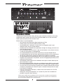
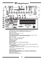
1
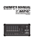
Compressor
off
max
Distortion
Mix
dry
Bass
Resonance
Protect
Freq
wet
400
tight
loose
400 Hz
Gain
Bass
stortion
Di 5
5
0
Low-Mid
0
150
Hz
1.5k
Hi-Mid
metric M
id
ra 0
Pa
0
Treble
Scoop
0
5
MASTER
Effects
4 5
5
7
2
8
1
0
10
0
-15
10
+15
-15
+15
cut
boost
-15
+15
-15
+15
0
10
0
10
Power
6
3
9
0
10
Inputs
0
-6
Post-EQ
Tube
Mute
Line Out
DynaBass
IN
Pre-EQ
Solid-State
Out
Distortion
Limiter
800H
Pre-amp
MODEL TYPE: YS1035
D ynaB a s s 800H
B A S S
G U I T A R
A M P L I F I E R
IMPORTANT SAFETY INSTRUCTIONS
The exclamation point within an equilatereal
triangle is intended to alert the user to the
presence of important operating and
maintenance (servicing) instructions in the
literature accompanying the appliance.
This lightning flash with arrowhead symbol,
within an equilateral triangle, is intended to alert
the user to the presence of uninsulated
“dangerous voltage” within the product’s enclosure
that may be of sufficient magnitude to constitute a risk of
electric shock to persons.
Le point d’exclamation à l’intérieur d’un triangle équilatéral
est prévu pour alerter l’utilisateur de la présence
d’instructions importantes dans la littérature accompagnant l’appareil en ce qui concerne l’opération et la
maintenance de cet appareil.
Ce symbole d’éclair avec tête de flèche dans un triangle
équilatéral est prévu pour alerter l’utilisateur de la présence
d’un « voltage dangereux » non-isolé à proximité de l’enceinte
du produit qui pourrait être d’ampleur suffisante pour présenter
un risque de choque électrique.
S2125A
FOLLOW ALL INSTRUCTIONS
Instructions pertaining to a risk of fire,
electric shock, or injury to a person
SUIVEZ TOUTES LES INSTRUCTIONS
Instructions relatives au risque de feu,
choc électrique, ou blessures aux personnes
CAUTION: TO REDUCE THE RISK OF ELECTRIC
AVIS: AFIN DE REDUIRE LES RISQUE DE CHOC
ELECTRIQUE, N’ENLEVEZ PAS LE COUVERT (OU LE
PANNEAU ARRIERE) NE CONTIENT AUCUNE PIECE
SHOCK, DO NOT REMOVE COVER (OR BACK).
NO USER SERVICEABLE PARTS INSIDE.
REPARABLE PAR L’UTILISATEUR.
REFER SERVICING TO QUALIFIED
SERVICE PERSONNEL.
CONSULTEZ UN TECHNICIEN QUALIFIE
POUR L’ENTRETIENT
Read Instructions: The Owner’s Manual should be read and
understood before operation of your unit. Please, save these instructions for future reference and heed all warnings.
Clean only with dry cloth.
Packaging: Keep the box and packaging materials, in case the unit
needs to be returned for service.
Warning: To reduce the risk or fire or electric shock, do not expose
this apparatus to rain or moisture. Do not use this apparatus near water!
Warning: When using electric products, basic precautions should
always be followed, including the following:
Your unit should be connected to a power source only of the voltage specified in the
owners manual or as marked on the unit. This unit has a polarized plug. Do not use
with an extension cord or receptacle unless the plug can be fully inserted. Precautions should be taken so that the grounding scheme on the unit is not defeated.
Hazards
Do not place this product on an unstable cart, stand, tripod, bracket or table. The
product may fall, causing serious personal injury and serious damage to the product.
Use only with cart, stand, tripod, bracket, or table recommended by the manufacturer
or sold with the product. Follow the manufacturer’s instructions when installing the
product and use mounting accessories recommended by the manufacturer.
The apparatus should not be exposed to dripping or splashing water; no objects
filled with liquids should be placed on the apparatus.
Terminals marked with the “lightning bolt” are hazardous live; the external wiring
connected to these terminals require installation by an instructed person or the use of
ready made leads or cords.
Ensure that proper ventilation is provided around the appliance. Do not install near
any heat sources such as radiators, heat registers, stoves, or other apparatus
(including amplifiers) that produce heat.
No naked flame sources, such as lighted candles, should be placed on the apparatus.
Power Cord
Do not defeat the safety purpose of the polarized or grounding-type plug. A polarized plug
has two blades with one wider than the other. A grounding type plug has two blades and a
third grounding prong. The wide blade or the third prong are provided for your safety. If the
provided plug does not fit into your outlet, consult an electrician for replacement of the
obsolete outlet. The AC supply cord should be routed so that it is unlikely that it will be
damaged. If the AC supply cord is damaged DO NOT OPERATE THE UNIT.
Unplug this apparatus during lightning storms or when unused for long periods of time.
The unit should be serviced only by qualified service personnel.
Emballage: Conservez la boite au cas ou l’appareil devait être
retourner pour réparation.
Avertissement: Pour réduire le risque de feu ou la décharge
électrique, n'exposez pas cet appareil à la pluie ou à l'humidité.
N’utilisez pas cet appareil près de l’eau!
Attention: Lors de l’utilisation de produits électrique, assurez-vous
Power Sources
Service
Veuillez Lire le Manuel: Il contient des informations qui devraient
êtres comprises avant l’opération de votre appareil. Conservez.
Gardez S.V.P. ces instructions pour consultations ultérieures et
observez tous les avertissements.
Nettoyez seulement avec le tissu sec.
d’adhérer à des précautions de bases incluant celle qui suivent:
Alimentation
L’appareil ne doit être branché qu’à une source d’alimentation correspondant au
voltage spécifié dans le manuel ou tel qu’indiqué sur l’appareil. Cet appareil est
équipé d’une prise d’alimentation polarisée. Ne pas utiliser cet appareil avec un
cordon de raccordement à moins qu’il soit possible d’insérer complètement les trois
lames. Des précautions doivent êtres prises afin d’eviter que le système de mise à la
terre de l’appareil ne soit désengagé.
Risque
Ne pas placer cet appareil sur un chariot, un support, un trépied ou une table instables.
L’appareil pourrait tomber et blesser quelqu’un ou subir des dommages importants.
Utiliser seulement un chariot, un support, un trépied ou une table recommandés par le
fabricant ou vendus avec le produit. Suivre les instructions du fabricant pour installer
l’appareil et utiliser les accessoires recommandés par le fabricant.
Il convient de ne pas placer sur l’appareil de sources de flammes nues, telles que
des bougies allumées.
L’appeil ne doit pas être exposé à des égouttements d’eau ou des éclaboussures
et qu’aucun objet rempli de liquide tel que des vases ne doit être placé sur l’appareil.
Assurez que lappareil est fourni de la propre ventilation. Ne procédez pas à
l’installation près de source de chaleur tels que radiateurs, registre de chaleur, fours
ou autres appareils (incluant les amplificateurs) qui produisent de la chaleur.
Les dispositifs marqués d’une symbole “d’éclair” sont des parties dangereuses
au toucher et que les câblages extérieurs connectés à ces dispositifs de
connection extérieure doivent être effectivés par un opérateur formé ou en utilisant
des cordons déjà préparés.
Cordon d’Alimentation
Ne pas enlever le dispositif de sécurité sur la prise polarisée ou la prise avec tige de
mise à la masse du cordon d’alimentation. Une prise polarisée dispose de deux
lames dont une plus large que l’autre. Une prise avec tige de mise à la masse
dispose de deux lames en plus d’une troisième tige qui connecte à la masse. La
lame plus large ou la tige de mise à la masse est prévu pour votre sécurité. La prise
murale est désuète si elle n’est pas conçue pour accepter ce type de prise avec
dispositif de sécurité. Dans ce cas, contactez un électricien pour faire remplacer la
prise murale. Évitez d’endommager le cordon d’alimentation. N’UTILISEZ PAS
L’APPAREIL si le cordon d’alimentation est endommagé.
Débranchez cet appareil durant les orages ou si inutilisé pendant de longues périodes.
Service
Consultez un technicien qualifié pour l’entretien de votre appareil.
safety-4v5.eps • April 3/2007
Compressor
off
Distortion
Mix
max
dry
Bass
Resonance
Protect
Freq
wet
400
tight
loose
400 Hz
Gain
Bass
stortion
Di 5
5
Low-Mid
0
0
150
r
Pa
Hz
1.5k
Hi-Mid
r
amet ic Mid
0
0
Treble
Scoop
0
5
MASTER
Effects
4 5
5
7
2
8
1
0
10
0
-15
10
+15
-15
+15
cut
boost
-15
+15
-15
+15
0
10
0
10
Power
6
3
9
0
10
Inputs
0
-6
Post-EQ
Tube
DynaBass
IN
Pre-EQ
Mute
Solid-State
800H
Out
Line Out
Distortion
Limiter
Pre-amp
Lift
Tip:
Dist.
EFX
GND
Ring:
Effects
Footswitch
Tuner
Amp In
Line Out
Send
Rtn
Circuit
Breaker
Press to Reset
SPEAKER OUTPUTS
ATTENTION: KEEP THE SIDE EXHAUST
VENTS AND REAR INTAKE VENTS
CLEAR OF OBSTRUCTIONS!
A-Z1019 / 1v5
ATTENTION: ASSUREZ-VOUS DE NE PAS
OBSTRUER LES BOUCHES DE SORTIE D'AÉRATION
SUR LES CÔTÉS ET CELLES D'ENTRÉE
D'AÉRATION SUR LE PANNEAU ARRIÈRE!
DynaBass
DISCONNECT POWER
BEFORE SERVICING!
DEBRANCHER L’APPEREIL AVANT
D’ENLEVER LES COUVERCLES!
B
Y
800H
BE
PREA
M
P
THIS UNIT MUST BE GROUNDED!
CET APPAREIL DOIT ETRE MIS Á TERRE!
H
DESIGNED & MANUFACTURED BY
YORKVILLE SOUND • TORONTO, CANADA
TU
Y
Min 2 ohms
MODEL TYPE: YS1035
RI
G
SPEAKON™ Pin
Configuration 1+/1–
L
D T
ECHNO
O
DynaBass 800H
The Traynor DynaBass 800H has been designed with the needs of professional bass guitar
players in mind. We believe you will find your Traynor DynaBass 800H to be dependable and
versatile for years to come.
When you need the extras, they’re all here
•
•
•
•
•
•
•
•
•
•
•
•
•
•
•
Selectable Solid-State or Tube input gain
Inputs for either Passive (0 dB) or Active basses (-6 dB).
A tube preamp for warmth, and a solid-state output stage for definition.
Gain and Distortion controls let you dial-in the perfect amount of warmth and even overdrive.
The Distortion circuit can be activated by using the switch on the front panel or by
using an optional footswitch.
The Distortion Mix control lets you blend-in the amount of tube distortion.
The Scoop control lets you tailor your sound precisely and uniquely by emphasizing
lows and highs while reducing the midrange.
The Resonance control allows you to tweak the bass tone from tight to loose.
Five-band, active tone shaping controls (including a fine-tunable Parametric Mid control).
Footswitchable external effects patching with an Effects Return level control
and footswitch jack.
An easy-to-use Compressor circuit provides even more detailed control of your bass dynamics.
A separate, selectable Limiter circuit helps prevent output-stage clipping-distortion.
A Tuner Out jack lets you keep your tuner connected without affecting your signal
path so it’s always available for quick reference and adjustments. The Mute button
ensures that the audience doesn’t hear you tuning!
Balanced ¼-inch TRS and XLR line outs selectable between Pre-EQ (real D.I.) or Post-EQ.
Speakon™ and ¼-inch speaker outputs (all jacks are in parallel, min 2-ohm load).
Please take a little time to read the following instructions; then plug in, switch on, and unleash
your musical creativity!
1
1
3
5
4
Compressor
off
6
7
8
9
10
Distortion
Mix
max
dry
12
14
13
Bass
Resonance
Protect
Freq
wet
400
tight
loose
400 Hz
Gain
Bass
stortion
Di 5
5
Low-Mid
0
0
150 Hz
1.5k
Hi-Mid
metric M
id
ra 0
Pa
Treble
0
Scoop
0
5
MASTER
Effects
4 5
5
7
2
8
1
0
10
0
-15
10
+15
-15
+15
cut
boost
-15
+15
-15
+15
0
10
0
10
Power
6
3
9
0
10
Inputs
0
-6
Post-EQ
Tube
DynaBass
IN
Pre-EQ
Solid-State
800H
Out
Mute
Line Out
Distortion
Limiter
15
20
4
11
Pre - a mp
2
16
19
18
20
21
Lift
Tip:
Dist.
EFX
GND
Ring:
Effects
Tuner
Amp In
Line Out
Rtn
Press to Reset
SPEAKON™ Pin
22
Send
Configuration 1+/1–
SPEAKER OUTPUTS
ATTENTION: KEEP THE SIDE EXHAUST
VENTS AND REAR INTAKE VENTS
CLEAR OF OBSTRUCTIONS!
Min 2 ohms
MODEL TYPE:YS1035
A-Z1019 / 1v5
ATTENTION: ASSUREZ-VOUS DE NE PAS
OBSTRUER LES BOUCHES DE SORTIE D'AÉRATION
SUR LES CÔTÉS ET CELLES D'ENTRÉE
D'AÉRATION SUR LE PANNEAU ARRIÈRE!
DynaBass
3
4 5 6
7
8 9 10 11
12
13
14
15
16
17
18
19
20
21
22
23
24
1
2
800H
DISCONNECT POWER
BEFORE SERVICING!
DEBRANCHER L’APPEREIL AVANT
D’ENLEVER LES COUVERCLES!
B
Y
DESIGNED & MANUFACTURED BY
YORKVILLE SOUND • TORONTO, CANADA
BE
PREA
M
P
THIS UNIT MUST BE GROUNDED!
CET APPAREIL DOIT ETRE MIS Á TERRE!
H
24
TU
Y
23
Footswitch
Circuit
Breaker
RI
G
17
L
D T
ECHNO
O
Tube and Solid-State Pre-Amp mode switch
0dB / Passive and -6dB / Active Input Jacks – ¼-inch phone jacks.
Gain control
Distortion Switch, Mix and control
Adjustable Compressor
Tone Controls – Bass, Low-Mid, Hi-Mid and Treble.
Semi-Parametric Mid tone control
Scoop control.
Effects Return control and LED
Bass Resonance control
Switchable Limiter
Master control
Protect LED
Power LED and Power switch
Mute switch
Distortion and Effects Return Footswitch – ¼-inch TRS phone jack
Tuner out – ¼-inch phone jack
Line Out XLR Jack and Selector Switch – Switch between Pre-EQ and Post-EQ settings
Ground Lift switch
Amp In Jack
EFX Send and EFX Return Jacks – ¼-inch TRS phone jacks
Speaker Output jacks – ¼-inch and Speakon™ connectors
Circuit Breaker
AC Power connector
2
1. Preamp Mode Switch
Depending on your preference, choose either solid-state or tube gain input for the preamp.
2. 0dB / Passive and -6dB / Active Input Jacks
We suggest the following: use the 0dB/Passive input for bass guitars with passive
electronics, like single-coil and humbucking pickups; use the -6dB/Active input for active
pickups (or extremely ‘hot’ pickups). However, you may prefer to run your active pickup bass
guitar into the 0dB/Passive input for an intentional aggressive sound – you are in control.
User Tip: Don’t use both inputs at the same time as they’re not intended for connecting more
than one instrument at a time.
3. Gain Control
The Gain control is a volume adjustment for the preamp, which is selectable - using either
solid-state or tube circuitry. The tube circuitry features a single 12AX7A (dual-triode) preamp
tube. The Gain control should normally be set around the middle, which should be the
position for most basses. If your bass has an unusually low output, increase the Gain control
to the desired level, conversely for higher output basses use a lower setting. Increasing the
Gain control also affects the level of distortion when the Distortion feature is engaged.
4. Distortion Switch, Mix and Control
The Distortion feature controls the amount of tube distortion (saturation) in the signal. The tube
distortion is powered by a 12AX7A, dual-triode preamp tube. Activate the circuit by depressing
the Distortion mode switch or using an optional footswitch (AFS-2). The red LED, above the
Distortion switch, will illuminate indicating Distortion mode is active. To achieve higher levels of
overdrive, increase the Gain control at the preamp stage. If you want your distortion level to
go beyond the usual threshold into modern lead-style distortion, increase the Distortion control
fully clockwise. Naturally, there will be some extra noise coming out of the amplifier at this high
setting. This is a normal compromise when achieving so much overdrive.
User Tip: Many unique sounds can be obtained by changing some controls in conjunction
with the Distortion control. Some bassists prefer minimal distortion with a lot of Scoop, some
may prefer massive overdrive (and lots of midrange growl) and others may go for that deep
dry bass. These sounds can be achieved easily by adjusting the Scoop, the Distortion and the
Distortion’s Mix controls in conjunction with each other.
User Tip: The Distortion circuit can also be activated by an optional footswitch (AFS-2). A red
LED, located directly above the Distortion switch, will illuminate. Some players find this useful
as a boost for loud passages or soloing.
Note, when using the footswitch the front panel Distortion selection switch is deactivated.
The Distortion Mix control becomes active when the Distortion mode is activated. This control
blends an underlying clean tone below the distorted tone. In the Dry counter-clockwise setting,
clean signal is allowed to dominate the mix with no distortion. When rotated clockwise, into the
Wet region, the distortion sound becomes more apparent. The Distortion overdrive will continue
to increase until it is the dominant sound in the mix (fully Wet position). This helps you achieve
a perfect Wet/Dry blend between a completely clean and completely saturated distortion tone.
This is a handy feature that puts you in control of your distorted tone.
5. Compressor
To increase the consistency of your tone and further the performance of the power amplifier,
we have provided an adjustable compressor. This compressor is fairly simple to use, with
only a simple threshold control to make adjustments. The compression ratio is 2:1 and the
attack/release-time is preset optimally.
Note: To use the Compressor, rotate the control clockwise until the desired threshold is
reached. It will be apparent to you audibly as well as visually; a red LED (located to the right of
the control) will illuminate as the compressor limits the signal. The LED will also indicate how
much compression is being applied by its intensity and duration.
3
6. Tone Controls
Each tone control permits a wide range of adjustment. The five overlapping controls cover the
entire audio spectrum. The Bass adjusts the level of the low frequency range, Low Mid the next
range up, Hi Mid covers higher notes and middle harmonics and the Treble control regulates
the upper harmonic range. Each tone control has a variable boost and/or cut of 15 db. The
center position denotes a neutral or nominal setting. The Parametric Mid control is described in
detail in section 7, below.
User Tip: It’s a good idea, when starting out, to center all tone controls. While playing, adjust
them until you achieve the desired sound. Remember, if the Parametric Mid control is set at 0,
rotating the Frequency control will have no effect.
7. Parametric Mid Control
The Parametric Mid control enables adjustments to be centered on frequencies
ranging from 150 Hz – 15 kHz.
User Tip: To use this control, set the position of the Parametric Mid level control to cut or boost.
Rotate the Frequency control until the desired frequency range is found. Once the frequency
range is chosen, adjust the Parametric Mid level until the desired cut or boost level is achieved.
User Tip: Try using the Parametric Mid in conjunction with the Scoop feature. When using the
Parametric Mid, it’s possible to enhance the Scoop’s capabilities by letting the two tone-shaping
controls work in tandem. If you like the added bottom of the Scoop but wish to soften the midrange
at 1 kHz (but still maintain the higher frequencies); adjust the Parametric Mid Frequency control
to 1.0 kHz and then use the Parametric Mid level control to cut as much as you need. The 400 Hz
frequency has been conveniently marked on the Parametric Mid’s Frequency control.
8. Scoop Control
The Scoop enhances the tone of the bass by shaping the mid frequencies around 400 Hz.
By shaping the bottom-end fundamentals and high frequency brilliance subtleties normally
hidden are revealed. The Scoop shapes specific upper and lower frequencies while notching
particular mid frequencies. It utilizes a variable tone curve that reacts differently depending
on where it is set. The result is a greatly expanded tonal range and control. As shown on
the front panel, the center frequency of the scoop is centered around 400 Hz. If you desire
more scoop, turn the parametric mid frequency control to 400 Hz and set the gain counterclockwise to cut until the desired amount is reached.
User Tip: As with the tone controls, it’s recommended to set the Scoop control initially at the
mid point. Adjust it slowly, either way, until the desired tone is achieved.
Tip: Combine the Scoop, the Distortion and Distortion Mix for unparalleled levels of tonal
control. Set the Distortion and the Distortion Mix to their maximums and play your bass while
slowly rotating the Scoop from its off position to its MAX position, you’ll find the variation in the
effect to be quite dramatic and yet very musical at the same time.
9. Effects Return Blend Control
Use the Effects Send jack to send a dry, uneffected signal to an external effects unit. The externally
processed signal then can return to the amplifier through the Effects Rtn jack. The Effects Rtn blend
control regulates how much of the effected signal is blended with the dry signal (un-effected signal).
This can range from totally dry (without effects) to very wet (effects applied).
User Tip: If a wetter signal is desired, set the output signal from the external effects
processor to a high output.
10. Bass Resonance Control
The Bass Resonance control adjusts the amount of low frequency damping of the amplifier.
Turning the control clockwise towards Loose reduces the damping factor and allows the
resonance of the speaker cabinet to be more pronounced. Setting the control towards Tight
increases the damping factor to achieve a punchier sound.
11. Selectable Limiter
In order to prevent hard clipping of the power amplifier, a selectable limiter is provided.
4
12 Master Volume Control
The Master volume control adjusts the overall signal level of the amplifier.
13. Protect LED
The red Protect LED displays the status of the internal protection circuitry. When the DynaBass
800H is initially powered up internal protection circuits are activated, no output will be heard until
the red Protect LED automatically shuts off. In a rare case of amplifier shutdown or if the output is
shorted, the amplifier will take approximately 15-20 seconds to reinitialize and obtain full power.
14. Power
The LED above the Power switch will illuminate when the unit is on
15. Mute Switch
The Mute switch disengages the preamp signal from the Line Out and power amplifier,
disabling signals sent to the mixing console and speaker cabinets. The Tuner Out jack is still
enabled (see Tuner Out in the Rear Panel section).
Rear Panel
16. Dual Footswitch Jack (Distortion and EFX-Return)
A dual footswitch jack can be used to switch the Distortion and the external Effects on and off.
The footswitch uses a standard TRS ¼-inch based dual footswitch (AFS-2). When either
effect is activated, corresponding LED’s on the amplifier will illuminate on and off (and on the
footswitch as well). The Effects are only switchable by the footswitch, but the Distortion can
be enabled or disabled by either the footswitch or the switch located on the front panel. The
footswitch control overrides the front panel switches.
17. Tuner
The Tuner out ¼-inch jack sends the signal from your bass guitar to an outboard instrument
tuner. Simply connect one end of a ¼-inch shielded cable to the Tuner Out jack and the other
to the instrument tuner. Pressing in the Mute button will mute the output to the speakers as
well as to the line out, but not the Tuner out.
Tip: Leave your tuner connected to the Tuner Out jack and Mute the signal any time
you wish to tune in silence. A very handy feature when onstage and the unpleasant
sound of tuning is not something you wish the audience to hear amplified through your
performance speakers or the sound system.
18. XLR Line Out Jack
This jack is used to connect directly to mixing consoles. You may prefer to use this when
performing live or recording in the studio.
Selecting the Pre-EQ option in the Line Out mode selection switch (located on the front
panel) makes the Line Out behave like a typical D.I. box: it provides a pre-EQ and pre-EFX
signal. The Post-EQ option sends the signal post-EQ and post-EFX, which enables the output
to drive another amplifier or the mixing console.
Note: When the Mute switch is engaged, a signal will not be sent to the mixing console
through the XLR output.
19. Ground Lift Switch
The Ground Lift switch is located next to the balanced Line Out XLR on the rear panel. If
hum is detected, when connecting from the balanced Line Out XLR to a mixing console (or
any other audio device), lift the ground (pin 1) by pressing the Ground Lift switch in.
20. Amp In ¼ -inch Jack
The balanced Amp In jack is located on the rear panel of the DynaBass 800H. The Amp In jack
provides a direct path to the DynaBass 800H’s power amplifier, bypassing the preamp. The Master
control still controls the overall output level. Multiple DynaBass 800H’s can be linked together by
using the DynaBass 800H’s balanced XLR Line Out to additional DynaBass 800H Amp In jacks.
5
XLR Plug
(Male)
1/4-inch T.R.S.
Phone Plug
Tip = 0°
Ring = 180°
1
2
3
Sleeve = Ground
Pin 1 = Ground
Pin 2 = 0°
Pin 3 = 180°
Balanced 1/4-inch T.R.S. to Balanced XLR
21. Effects Send and Return ¼ -inch Jacks
External effects processors are provided with a balanced post-EQ signal from the Effect
Send jack. The balanced Return jack is used to return effects (processed audio signals) back
into the DynaBass 800H. The Effects Return control, located on the front panel, regulates
the blend of effected and un-effected signal. This input can also be used as an auxiliary input
for mixing in a secondary source of audio such as pre-recorded music.
User Note: The Effects Send jack can also be used as additional line out for sending signals to
another power amplifier. The output of this jack is not muted when the Mute switch is enabled.
22. Output Jacks
The ¼-inch and Speakon™ jacks are used to connect extension speaker cabinets. All
speaker output jacks are in connected in parallel; the minimum load impedance is 2-ohms
(e.g. two 4-ohm or four 8-ohm cabinets).
23. Circuit Breaker
In the event the DynaBass 800H amplifier draws excessive electrical current from the wall
receptacle, the circuit breaker will trip to cut power to the unit and prevent further damage
from occurring. Once the amplifier has cooled, the breaker may be reset to re-enable
operation. If the amplifier’s circuit breaker continues to trip, please have the DynaBass
800H inspected by a qualified service technician.
24. AC Power Receptacle
The DynaBass 800H is equipped with a standard grounded IEC power receptacle. Only use
the supplied removable power cord or one that uses a minimum of 16 gauge wire.
25. Cooling system
Two 3-inch fans cool the DynaBass 800H. The fans are run at low speed and the speed selfadjusts depending on how hard the amplifier is working. The air intake vents are located at the
rear of the amplifier and on the top (near the back). The exhaust vents are located at the sides.
Caution: The rear vent must be kept clear in order for the air to enter into the amplifier. The
side vents are used to allow warm air out of the unit. Allow at least an inch clearance for
each side. Always keep the rear of the unit unobstructed. Rack-mounting the DynaBass 800H
chassis will not affect intake/exhaust airflow as long as the rear of the rack casing is open
during operation and 1 inch of clearance along the sides is unobstructed.
26. Preamp Tube Replacement
Use only Yorkville Sound part number “12AX7SORTED” when replacing the preamplifier
tube, these have been specifically selected for this product. Please refer to the Service
Manual for more information.
Tube Access
1. Unplug the DynaBass 800H's AC power cord
2. Remove the amplifier's top plate/lid
3. Loosen the 2 screws which hold the piece of circuit board retaining the tube.
4. Replace the tube and then follow the procedure above in reverse order 3, 2, 1.
6
Compressor
off
Distortion
Mix
max
dry
Bass
Resonance
Protect
Freq
wet
400
tight
loose
400 Hz
Gain
Bass
stortion
Di 5
5
Low-Mid
0
0
150
r
Pa
Hz
1.5k
Hi-Mid
r
amet ic Mid
0
0
Treble
Scoop
0
5
MASTER
Effects
4 5
5
7
2
8
1
0
10
0
-15
10
+15
-15
+15
cut
boost
-15
+15
-15
+15
0
10
0
10
Power
6
3
9
0
10
Inputs
0
-6
Post-EQ
Tube
DynaBass
IN
Pre-EQ
Mute
Solid-State
800H
Out
Line Out
Distortion
Limiter
Pr e- amp
Lift
Tip:
Dist.
EFX
GND
Ring:
Effects
Footswitch
Tuner
Amp In
Line Out
Send
Rtn
Circuit
Breaker
Press to Reset
SPEAKER OUTPUTS
ATTENTION: KEEP THE SIDE EXHAUST
VENTS AND REAR INTAKE VENTS
CLEAR OF OBSTRUCTIONS!
A-Z1019 / 1v5
ATTENTION: ASSUREZ-VOUS DE NE PAS
OBSTRUER LES BOUCHES DE SORTIE D'AÉRATION
SUR LES CÔTÉS ET CELLES D'ENTRÉE
D'AÉRATION SUR LE PANNEAU ARRIÈRE!
DynaBass
DISCONNECT POWER
BEFORE SERVICING!
DEBRANCHER L’APPEREIL AVANT
D’ENLEVER LES COUVERCLES!
B
Y
800H
H
DESIGNED & MANUFACTURED BY
YORKVILLE SOUND • TORONTO, CANADA
TU
BE
PREA
M
P
THIS UNIT MUST BE GROUNDED!
CET APPAREIL DOIT ETRE MIS Á TERRE!
Y
Min 2 ohms
MODEL TYPE: YS1035
RI
G
SPEAKON™ Pin
Configuration 1+/1–
L
D T
ECHNO
O
DynaBass 800H
L’amplificateur Traynor DynaBass 200 a été conçu pour satisfaire aux besoins du bassiste
professionnel. Nous croyons que votre Traynor DynaBass 800H sera un outil de travaille
fiable et polyvalent pour plusieurs années à venir.
Besoin d’extra? Ils sont disponibles:
• Gain d’entrée commutable entre Semi-conducteur ou Tube
• Entrée s pour basses Passive (0 dB) ou Active (-6 dB).
• Un préamplificateur à tube pour un son chaud, et un étage de sortie à semiconducteur pour une plus grande définition.
• Contrôles de Gain et Distortion vous permettent de régler le mélange parfait d’un son
chaud et même overdrive.
• Le circuit Distortion peut être activé à l’aide du commutateur sur le panneau avant ou
à l’aide d’un commutateur au pied optionnel.
• Le contrôle Distortion Mix vous permet d’atteindre le niveau de Distortion désiré.
• Le contrôle Scoop vous offre une façon unique et précise de faire la mise au point finale
de votre son. Il rehausse les graves et les aiguës tout en réduisant les médianes.
• Le contrôle Résonance permet l’obtention d’un son de graves plus serré ou plus relaxe.
• Contrôles actifs de tonalité à Cinq bandes. (Incluant un réglage de précision pour les
médianes paramétri-ques).
• Raccordement d’effet externe avec contrôle de niveau pour le retour d’effet et prise
pour commutateur au pied.
• Un circuit de compression facile à utiliser offre un contrôle encore plus détaillé sur votre tonalité.
• Un circuit commutable de limiteur séparé aide à prévenir l’écrêtage à l’étage de sortie.
• La prise Tuner Out vous permet de garder votre accordeur électronique connecté
et (toujours) disponible pour référence rapide. Le bouton Mute permet de couper
le son durant l’accordage.
• Prise de sortie ligne symétrique ¼ PBM et XLR commutable entre Pré-EQ
(I.D. réel) ou Post-EQ.
• Sorties pour haut-parleur Speakon™ et ¼ (toutes les prises sont raccordées en
parallèle, charge de 2-ohm minimum).
Prenez S.V.P. le temps de vous familiariser avec les instructions suivantes; ensuite branchez
votre instrument, mettez l’appareil en marche et savourez une sonorité riche et satisfaisante
qui vous permettra d’explorer votre créativité musical
7
1
3
5
4
Compressor
off
6
7
8
9
10
Distortion
Mix
max
dry
12
14
13
Bass
Resonance
Protect
Freq
wet
400
tight
loose
400 Hz
Gain
Bass
stortion
Di 5
5
Low-Mid
0
0
150 Hz
1.5k
Hi-Mid
metric M
id
ra 0
Pa
Treble
0
Scoop
0
5
MASTER
Effects
4 5
5
7
2
8
1
0
10
0
-15
10
+15
-15
+15
cut
boost
-15
+15
-15
+15
0
10
0
10
Power
6
3
9
0
10
Inputs
0
-6
Post-EQ
Tube
DynaBass
IN
Pre-EQ
Solid-State
800H
Out
Mute
Line Out
Distortion
Limiter
15
20
4
11
Pre - a mp
2
16
19
18
20
21
Lift
Tip:
Dist.
EFX
GND
Ring:
Effects
Tuner
Send
Rtn
Press to Reset
SPEAKON™ Pin
22
Amp In
Line Out
Configuration 1+/1–
SPEAKER OUTPUTS
ATTENTION: KEEP THE SIDE EXHAUST
VENTS AND REAR INTAKE VENTS
CLEAR OF OBSTRUCTIONS!
Min 2 ohms
MODEL TYPE:YS1035
A-Z1019 / 1v5
ATTENTION: ASSUREZ-VOUS DE NE PAS
OBSTRUER LES BOUCHES DE SORTIE D'AÉRATION
SUR LES CÔTÉS ET CELLES D'ENTRÉE
D'AÉRATION SUR LE PANNEAU ARRIÈRE!
DynaBass
3 4 5 6 7 8 9 10 11 12 13 14 15 16 1
2
17
18
21 22 23 24 19
20
800H
DISCONNECT POWER
BEFORE SERVICING!
DEBRANCHER L’APPEREIL AVANT
D’ENLEVER LES COUVERCLES!
B
Y
DESIGNED & MANUFACTURED BY
YORKVILLE SOUND • TORONTO, CANADA
BE
PREA
M
P
THIS UNIT MUST BE GROUNDED!
CET APPAREIL DOIT ETRE MIS Á TERRE!
H
24
TU
Y
23
Footswitch
Circuit
Breaker
RI
G
17
L
D T
ECHNO
O
Sélecteur de mode de préamplificateur à Lampe et à semi-conducteurs
Prises d’entrées ¼ de pouce 0dB / Passive et -6dB / Active
Contrôle de Gain
Sélecteur Distortion, Mixe et Contrôle
Compresseur Ajustable
Contrôles de Tonalité – Graves, Médianes Basses, Médianes Aiguës et Aigues.
Contrôle de Tonalité pour médianes Semi-Paramétrique
Contrôle Scoop.
Contrôle et DEL pour Retour d’Effet
Contrôle de Résonance de basses
Limiter Commutable
Contrôle Master
DEL Protect
DEL d’Alimentation et Commutateur d’Alimentation
Sélecteur Mute
Commutateur au pied Distortion et Retour d’Effet – prise ¼-de pouce Pointe
Bague Manchon
Sortie Pour Accordeur – prise ¼ de pouce.
Prise de Sortie Ligne XLR et Sélecteur – Permet de sélectionner les réglages Pré-EQ
ou Post-EQ.
Commutateur de découplage de masse
Prise de Amp In
Prises EFX Send et EFX Return – prise ¼ de pouce Pointe Bague Manchon.
Prise de sortie pour haut-parleur – Prise ¼ de pouce et connecteur Speakon™
Disjoncteur De Circuit
Connecteur d’Alimentation CA
8
1. Sélecteur de Préamplificateur
Selon vos préférences, vous pouvez choisir le mode de gain d’entrée à semi-conducteur ou
à lampe pour le préamplificateur.
2. Entrées 0dB / Passive et -6dB / Active
Ces entrées sont pour instruments. Utilisez l’entrée 0dB pour les guitares basses avec circuit
électronique passif normal, comme sur les basses dotées de micro à bobine simple ou micro
type humbucking. Utilisez l’entrée -6dB pour les basses avec micro à sortie élevée ou celles
avec micros actifs. Vous pouvez cepen-dant choisir de brancher votre guitare basse équipé
de micro actifs à l’entrée 0dB/Passive input pour ob-tenir délibérément un son plus agressif
– vous êtes l’artiste, vous décidez.
Conseil pratique: N’employez pas simultanément les deux entrées; elles ne sont pas conçu
pour permettre le branchement de plus qu’un instrument à la fois.
3. Contrôle de Gain
Le contrôle de Gain règle le volume du préamplificateur, qui est luimême commutable entre
circuit à semi-conducteur ou à lampe. Le circuit à lampe est équipé d’une lampe 12AX7A à
double triode. Le contrôle de Gain devrait normalement être réglé vers la position centrale.
Ce réglage devrait accommoder la plupart des guitares basses. Si le niveau de sortie
de votre basse est anormalement bas, augmentez le niveau du contrôle de gain jusqu’à
l’obtention du niveau désiré. D’autre part, pour les guitares basses avec niveau de sortie
plus élevé, utilisez un réglage réduit. Une augmentation du contrôle de Gain affecte aussi le
niveau de la section distortion lorsque la fonction de Distortion est engagée
4. Sélecteur Distortion, Mixe et Contrôle
La fonction de Distortion contrôle le niveau de saturation à lampe, appliqué au signal. Le circuit
de satura-tion à lampe est alimenté par une lampe de préamplificateur 12AX7A à double triode.
Le circuit est activé en appuyant sur le commutateur de mode Distortion ou par l’utilisation le
du commutateur au pied optionnel (AFS-2). La DEL verte, au-dessus du sélecteur Distortion,
s’illuminera pour indiquer que le mode Distortion a été acti-vé. Pour obtenir un niveau plus élevé
de saturation, augmentez le niveau du contrôle de gain à l’étage de pré amplification. Si vous
désirez un niveau de saturation moderne très élevé, augmentez le niveau du contrôle Distortion
dans le sens horaire jusqu’à la position maximum. Naturellement, il y a un peu plus de bruit
provenant de l’amplificateur de puissance lorsque vous utilisez des réglages extrêmes. Ceci est
normal, et parfaitement acceptable, étant donné le niveau de saturation si élevé.
Conseil: Plusieurs sonorités uniques peuvent être obtenues en changeant quelques contrôles
en conjonction avec le contrôle Distortion. Certains bassistes préfèrent très peu de distorsion
avec beaucoup de Scoop, certains autres préfèrent un son complètement saturé (et beaucoup
de grondement dans les médianes). D’autres préfèrent opter pour un réglage qui offre un son
grave profond. Ces différentes sonorités peuvent toutes être obtenues facilement en ajustant
conjointement les contrôles de Scoop, Distortion et Distortion Mix.
Conseil: Le circuit Distortion peut aussi être activé avec un commutateur au pied optionnel
(AFS-2). Une DEL verte, situé directement au-dessus du sélecteur Distortion, s’illuminera.
Certain musiciens en font un usage pratique pour augmenter le volume lors de passage à
niveaux plus élevés ou pour les solos.
Note, Lorsqu’un commutateur au pied est utilisé le sélecteur Distortion du panneau
avant est désarmé.
Le contrôle Distortion Mix devient actif quand le mode Distortion a été activé. Ce contrôle
mélange une sonorité claire sous-jacente en dessous du son saturé. Lorsque réglé à la
position Dry, sens anti-horaire, le signal clair domine le mélange, sans signal saturé. Quand
vous tournez le contrôle dans le sens horaire, vers la région Wet, le signal saturé devient
plus apparent. Le niveau du signal saturé Distortion continuera d’augmenter jusqu’à ce qu’il
domine le mélange (position Wet). Cela vous permet d’obtenir le mélange par-fait de signaux
Wet/Dry, d’un signal complètement clair à un signal complètement saturé. Une caractéristique pratique qui vous rend maître de votre son saturé
9
5. Compresseur
Un compresseur ajustable est prévu pour accroître la consistance de votre sonorité, et
parfaire la performance de l’amplificateur de puissance. Ce compresseur simple à utiliser,
est contrôlé par un simple contrôle de threshold. Le rapport du compresseur est réglé à 2:1
et son temps d’attaque / relâchement est préréglé pour le rendement optimal.
Conseil: Pour utiliser le compresseur, tournez le contrôle dans le sens horaire jusqu’à ce que le point
de seuil de déclenchement ait été atteint. Cela sera apparent de façon audible et aussi visible; une
DEL rouge (située à la droite du contrôle) s’illumine quand le signal est limité par le compresseur. La
DEL indique aussi combien de compression est appliquée par sa luminosité et sa duré.
6. Contrôles de Tonalité
Chaque contrôle de tonalité offre une gamme d’ajustement étendu. Les quatre contrôles à
chevau-chement couvrent entièrement la bande audio. Le contrôle Bass ajuste le niveau des
fréquences graves, le contrôle Low Mid ajuste le niveau de la gamme juste au-dessus des
graves, le contrôle Hi Mid couvre les notes les plus aiguës et les harmoniques médianes.
Le contrôle Treble ajuste la gamme des harmoniques supérieures. Chaque contrôle peut
augmenter ou réduire le niveau 15 dB. Un réglage central sur ces contrôles correspond
approximativement à un réglage neutre. La fonction du contrôle Parametric Mid est décrite
en détails dans la section 7 cidessous.
Conseil: il est parfois désirable de commencer avec les contrôles à la position centrale pour
ensuite les ajuster tout en jouant jusqu’à l’obtention du son désiré. Rappelez-vous ; si le
contrôle Parame-tric Mid est réglé à 0, le contrôle Frequency n’a aucun effet.
7. Contrôle Parametric Mid
Le contrôle Parametric Mid permet aux ajustements d’être centré sur des fréquences
couvrant une gamme de 150 Hz – 15 kHz.
Conseil: Pour utiliser ce contrôle, réglez la position du contrôle de niveau Parametric Mid de façon
à réduire ou augmenter le niveau. Tournez le contrôle Frequency jusqu’à ce que vous ayez obtenu
la gamme de fréquences désirée. Une fois la gamme de fréquences choisie, réglez le niveau du
contrôle Parametric Mid pour obtenir le niveau de coupure ou d’augmentation voulue.
Conseil: Essayez d’utiliser la commande Parametric Mid en conjonction avec la
caractéristique Scoop. En utilisant la fonction Parametric Mid, il est possible de rehausser
la capacité de la fonction Scoop en utilisant les deux contrôles de façonnement de tonalité
en tandem. Si vous aimez le re-haussement des graves de la fonction Scoop mais désirez
adoucir les médianes à 1Kz (tout en maintenant les fréquences aiguës); ajustez le contrôle
Parametric Mid Frequency à 1.0Kz et utilisez ensuite le contrôle de niveau Parametric Mid
pour couper selon vos désire. La fréquence de 400 Hz est identifiée sur le contrôle de
fréquence Parametric Mid pour en faciliter l’utilisation.
8. Contrôle Scoop
Le Scoop rehausse la tonalité des fréquences graves en façonnant les fréquences médianes
autour de 400 Hz. En façonnant les fondamentales des fréquences graves et la brillance des
fréquences aiguës, les subtilités normalement cachées sont révélées. Le Scoop façonne des
fréquences spécifiques des registres graves et aigus tout en coupant certaines fréquences
médianes. Le circuit utilise une courbe de tonalité variable qui réagit différemment selon
son réglage. Le résultat offre une gamme de tonalité grandement étendue et un niveau de
contrôle accrû sur la tonalité. Tel qu’indiqué sur le panneau avant, la fréquence centrale
du scoop est centrée autour de 400 Hz. Si vous désirez plus de scoop, réglez le contrôle
paramétrique de fréquence médiane à 400 et tournez le contrôle de gain dans le sens antihoraire jusqu’à l’obtention de la quantité de scoop désiré
Conseil: Tout comme avec les contrôles de tonalité, il est recommandé d’ajuster
initialement le contrôle de scoop à la position centrale. Ajustez le doucement, jusqu’à
l’obtention de la tonalité désirée.
Conseil: Combinez le contrôle de Scoop, celui de Distortion et de Distortion Mix pour un
contrôle sans précédent de votre tonalité. Réglez le contrôle Distortion et Distortion Mix à
leur position maximale et jouez votre instrument tout en tournant doucement le contrôle
Scoop de la position OFF jusqu’à la position MAX. Les variations sonores obtenues seront
dramatiques mais toujours musicales.
10
9. Contrôle de Mélange de Retour d’Effet
Un signal sec est acheminé à travers la prise EFX Send vers une unité de traitement de
signal externe. Ce signal est ensuite retourné à l’amplificateur par l’entremise de la prise
Effects Rtn. Le contrôle de mélange de l’Effects Rtn règle la quantité de signal affecté qui est
mélangé au signal dépourvu d’effet. La gamme de réglage passe par totalement dépourvu
d’effet à un signal pour la plus grande part affecté
Conseil: Pour l’obtention d’un signal encore plus affecté, augmentez le niveau de sortie de
l’unité de traitement de signal externe.
10. Contrôle de Résonance des Graves
Le Contrôle de résonance des graves ajuste la quantité d’amortissement des fréquences
graves de l’amplificateur. Tournez le contrôle dans le sens horaire vers loose pour réduire le
facteur d’amortissement et permettre à la résonance de l’enceinte à haut-parleur d’être plus
prononcé. Un réglage vers la position tight accroît le facteur d’amortissement pour aider à
obtenir un son plus percu-tant.
11. Limiteur Commutable
Pour prévenir l’écrêtage sévère de l’amplificateur de puissance, un limiteur commutable est prévu.
12. Contrôle Master Volume
Le contrôle Master volume permet l’ajustement du volume général de l’amplificateur.
13. DEL Protect
La DEL Protect rouge affiche la condition du circuit de protection interne. Lors de la mise
en marche initiale du DynaBass 800H, le circuit de protection interne est activé, il n’y aura
aucun son jusqu’à ce que la DEL rouge de protection s’éteigne. Dans les rares instances ou
l’amplificateur cesse de fonc-tionner ou s’il y a un court-circuit, l’amplificateur prendra environ
de 15 à 20 secondes pour la réinitiali-sation et l’obtention de la pleine puissance.
14. Alimentation
La DEL au-dessus du commutateur d’alimentation s’illumine quand l’appareil est en marche.
15. Commutateur Mute
Le commutateur Mute coupe le signal du préamplificateur à la sortie ligne et à
l’amplificateur de puis-sance, coupant ainsi les signaux acheminés à la table de mixage
et aux enceintes à haut-parleur. La sortie Tuner Out continuera de fonctionner (voir sortie
Tuner dans la section panneau arrière).
Panneau Arrière
16. Prise pour Commutateur au Pied Double (Distortion et EFX-Return)
Un commutateur au pied double peut être utilisé pour activer ou désactiver le Distortion et
l’effet externe. Utilisez un commutateur double au pied avec fiche standard PBM ¼ pouce
(AFS-2). Les DEL corres-pondantes sur l’amplificateur et le commutateur au pied s’illumine
quand l’effet est engagé. Les Effets ne peuvent être commutés que par le commutateur au
pied, mais le circuit Distortion peut être enga-gé/désengagé soit par le commutateur au pied
soit par le commutateur situé sur le panneau avant. Le commutateur au pied l’emporte sur le
commutateur du panneau avant.
17. Sortie pour Accordeur
La sortie Tuner de ¼ pouce achemine le signal de votre guitare basse à un accordeur
externe pour instru-ment musical. Vous n’avez qu’à raccorder une extrémité d’un câble blindé
¼ pouce à la prise Tuner Out et l’autre extrémité à l’accordeur électronique. Appuyez sur le
bouton Mute pour couper le son au haut-parleur et le son à la sortie ligne.
Conseil: Gardez votre accordeur branché à la prise Tuner Out et coupez le signal lorsque vous
voulez accorder votre instrument en silence. Une caractéristique très utile sur la scène. Le
procédé d’accordage n’est pas quelque chose que vous désirez faire entendre à votre audience!
11
18. Prise de Sortie Ligne Symétrique XLR
Cette prise est utilisée pour connecter directement à la console de mixage. Utilisez la lors de
performance live ou durant les sessions d’enregistrement au studio. Choisir l’option Pré-EQ
sur le sélecteur de mode de sortie ligne (situé sur le panneau avant) fera de sorte que la
sortie ligne fonctionnera comme une boite I.D. Vous obtiendrez un signal pré EQ et pré-EFX.
L’option Post-EQ achemine un signal Post-EQ et Post-EFX permettant à la sortie d’entraîner
un autre amplificateur ou une table de mixage.
Note: Quand le sélecteur Mute est engagé, le signal ne sera pas acheminé à la console de
mixage par l’entremise le la sortie XLR.
19. Commutateur Ground Lift
Le commutateur Ground Lift est situé à côté de la prise XLR de sortie ligne symétrique sur
le panneau arrière. S’il y a un bourdonnement quand vous connectez la sortie XLR ligne
symétrique à une console de mixage (ou autre appareil audio), débranchez la mise à la
masse (tige 1) en enfonçant le commuta-teur Ground Lift.
20. Prise Amp In ¼ -Pouce
L’entrée symétrique Amp In est située au panneau arrière du. La prise Amp In offre un
chemin direct à la section d’amplificateur de puissance du DynaBass 800H, contournant
ainsi la section de pré amplifica-tion. Le contrôle Master garde toutefois le contrôle sur le
volume général de sortie. Plusieurs DynaBass 800H peuvent être raccordés ensemble en
utilisant le signal à la prise de sortie ligne symétrique XLR du premier DynaBass 800H pour
acheminer le signal à la prise d’entrée ligne sur le DynaBass 800H additionnel.
XLR Plug
(Male)
1/4-inch T.R.S.
Phone Plug
Tip = 0°
Ring = 180°
1
2
3
Sleeve = Ground
Pin 1 = Ground
Pin 2 = 0°
Pin 3 = 180°
Balanced 1/4-inch T.R.S. to Balanced XLR
21. Prise ¼ de Pouce d’Envoi et de Retour Aux Effets
Le signal acheminé aux processeurs d’effet externe est symétrique post-EQ à partir de
la prise Effect Send. La prise symétrique de retour d’effets est utilisée pour retourner au
DynaBass 800H, le signal audio ayant été traité par l’appareil d’effet externe. Le contrôle
Effects Return, situé sur le panneau avant, règle le mélange des signaux affectés et
dépourvus d’effet. Cette entrée peut aussi être utilisée comme entrée auxiliaire pour
mélanger une source audio secondaire comme par exemple de la musi-que pré enregistrer.
Note: Cette prise peut aussi être utilisée comme sortie ligne additionnelle pour acheminer le
signal à un autre amplificateur de puissance. Le signal à cette prise n’est pas coupé quand
le sélecteur Mute est engagé.
22. Prises de Sortie
Les prises ¼ pouce et Speakon™ sont utilisés pour raccorder des enceintes à haut-parleur
supplémentaires. Les prises de sortie pour haut-parleur sont toutes branchées en parallèle.
La charge d’impédance minimum est de 2-ohms (ex.: deux enceintes de 4-ohms ou quatre
enceintes de 8-ohms).
12
23. Disjoncteur
Dans l’éventualité ou l’amplificateur DynaBass 800H tire de la prise murale une quantité
excessive de courant électrique, le disjoncteur déclenche et coupe ainsi l’alimentation à
l’appareil pour empêcher la possibilité de dommages additionnels. Quand l’amplificateur a
refroidit, le disjoncteur peut être réarmé pour permettre à nouveau l’opération. Si le disjoncteur
de l’amplificateur continue de déclancher, veuillez faire inspecter le DynaBass 800H par un
technicien qualifié de service.
24. Réceptacle d’Alimentation CA
Le DynaBass 800H est équipé d’un réceptacle d’alimentation IEC (composant électronique
intégré) standard avec branchement à la masse. Utilisez seulement le cordon d’alimentation
amovible fourni ou un cordon qui est fabriqué avec un fil de calibre 16.
25. Système de Refroidissement
Le DynaBass 800H est équipé de deux ventilateurs de trois pouces. Les ventilateurs tournent
normalement à vitesse réduite, et leur vitesse augmente selon l’emploi de l’amplificateur de
puissance. Les conduits d’entrée pour l’aération sont situés à l’arrière de l’amplificateur et sur
le dessus (vers l’arrière). Les conduits d’échappement sont situés sur les côtés.
Attention: Les conduits d’entrée pour l’aération sur le panneau arrière ne doivent pas
être obstruer pour permettre une bonne ventilation vers l’amplificateur. Les conduits
d’échappement sur les côtés sont utilisés pour permettre à l’air chaud d’évacuer. Prévoyez un
dégagement d’au moins un pouce sur chaque côté. L’arrière de l’appareil ne devrait jamais
être obstrué. Le montage en rack du DynaBass 800H n’affectera pas la circulation d’air si
vous vous assurez que l’arrière du rack reste ouvert durant l’opération et qu’il y a au moins un
pouce sans obstructions sur chaque côté.
26. Remplacement des Lampes de Préamplificateur
Quand vous remplacez les lampes de préamplificateur, employez seulement le numéro de pièce
Yorkville Sound “12AX7SORTED”. Ces lampes ont été spécifiquement sélectionnées pour ce
produit. Pour plus d’information, nous vous prions de vous référez au manuel de service.
Accès au Tube
1. Débranchez le cordon d'alimentation du DynaBass 800H
2. Retirez la plaque sur le dessus de l'amplificateur
3. Desserrez les 2 vis qui maintiennent la pièce de circuit imprimé sur laquelle est monté le tube.
4. Remplacez le tube et suivez la procédure ci-dessus dans l'ordre inverse 3, 2, 1.
13
Specifications
Type
Power @ min. impedance (Watts)
Minimum Impedance (ohms)
Burst Power - 2 cycle
Frequency Response (Hz +/-3dB)
Hum and Noise (dB)
Input Channels
Channel 1 - inputs
Channel 1 - controls
Channel 1 - switches
Master Volume Control
Input Sensitivity (mV)
Master Outputs
Line Out (type / configuration)
Line Out Sensitivity (Vrms)
Effects Loop / Location
Effects Footswitch / Function
Effects Return Sensitivity (Vrms)
LED Indicators
Protection
Limiter / Switchable
External speaker output / location
Headphone Jack
Bass Head
600 @8 ohms / 800 @4 ohms / 600 @2 ohms
2
1000 Watts
20hz - 20khz
-90dB Unweighted / -94db A weighted
1
2x 1/4 inch, 0dB / -6dB
5 Band EQ w/ parametric sweepable mid, Distortion
Limiter, Compressor, Distortion, Tuner Mute
Yes
80
Speakon™, 1/4-inch (x2)
Pre/Post EQ - XLR, Bal TRS
1
Rear
Distortion / Effects Loop
1
Power, Distortion, Compressor, Mute, EFX Rtn
Thermal, Short Circuit
Yes / Yes (Output Clip Limiter)
2 x 1/4 inch, 2 x Speakon™
No
Amp In (rear)
Parametric Mid
Blend level on EFX Return
Other Features
Wet/Dry Control on Distortion mode
Adjustable Compressor
Tuner mute switch and 1/4-inch tuner out jack
Bass Resonance
Tube/Solid State input selector switch
Dimensions (DWH, inches)
Dimensions (DWH, cm)
Weight (lbs / kg)
13 x 19 x 5
33 x 84 x 13
31.3 / 14.4
Spécifications
Type
Puissance @ impédance min.(watts)
Impédance minimum (ohms )
Amplificateur pour basses
600 @8 ohms / 800 @4 ohms / 600 @2 ohms
2
Puissance d’éclatement - 2 cycles
1000 Watts
Réponse en fréquence (Hz +/-3dB)
20hz - 20khz
Bruit et Bourdonnement (dB)
-90dB Non-Pondéré/ -94db A Pondéré
Canaux d’entrées
1
Entrées - Canal 1
2x 1/4 pouces, 0dB / -6dB
Commutateurs – Canal 1
EQ à 5 bandes avec médianes balayable parametrique, Gain à
lampe
Limiteur, Compresseur, Distortion, Tuner Mute
Contrôle Master Volume
Oui
Sensibilité d’entrée (mV)
80
Contrôle – Canal 1
Sorties Principales
Sorite Ligne (type / configuration)
Sensibilité de la Sortie Ligne (Vrms)
Boucle d’effet / Location
Commutateur au pied pour effet / Fonction
Sensibilité du retour d’effet (Vrms)
DEL Indicatrices
Protection
Limiteur / Commutable
Prise de sortie pour haut-parleur externe / location
Prise pour casque d’écoute
Autres Caractéristiques
Speakon™, 1/4 pouce (x2)
Pré/Post EQ - XLR, Sym PBM
1
Arrière
Distortion / Boucle d’effet
1
Alimentation, Distortion, Compresseur, Mute, retour EFX
Thermale, Court Circuit
Oui / Oui (Limiteur décrêtage de sortie)
2 x 1/4 pouces, 2 x Speakon™
Non
Entrée à l’amplificateur de puissance (arrière)
Médianes Parametrique
Mélange avec/sans effet sur le retour d’effet
Contrôle avec/sans effet sur le mode Drive
Compresseur Ajustable
Sélecteur Mute pour accordage et prise tuner out 1/4 pouce
Résonance Basses Fréquences
Sélecteur de mode d’entrée à Lampe/semi-conducteur
Dimensions (PLH, pouces)
Dimensions (PLH, cm)
Poids (livres / kg)
13 x 19 x 5
33 x 84 x 13
31.3 / 14.4
DynaBass 800H User Settings
Notes:
10
Pre- a mp
Solid-State
Tube
0
5
Gain
off
0
dry
0
Inputs
10
-6
wet
Distortion
Mix
stortion
Di 5
max
Compressor
-15
0
+15
Bass
-15
0
Mute
+15
Low-Mid
1.5k
boost
0
-15
0
Out
IN
Limiter
+15
Treble
Distortion
+15
Hi-Mid
-15
Line Out
Pre-EQ
Post-EQ
cut
150 Hz
metric M
id
ra 0
Pa
Freq
400
0
5
400 Hz
10
Scoop
0
0
4 5
10
6
MASTER
800H
10
1
2
3
loose
DynaBass
5
Effects
tight
Bass
Resonance
9
8
7
SETTINGS-USER-DynaBass800H-01-1v4
Power
Protect
DynaBass 800H User Settings
Notes:
Tube
0
5
off
0
0
-6
wet
Distortion
Mix
dry
Inputs
10
stortion
Di 5
max
Compressor
Gain
10
Pre- amp
Solid-State
-15
0
Bass
+15
0
+15
Low-Mid
-15
Mute
Freq
400
150 Hz
1.5k
metric M
id
ra 0
Pa
boost
0
+15
Hi-Mid
-15
0
Limiter
+15
Treble
-15
IN
cut
Post-EQ
Distortion
Out
Line Out
Pre-EQ
5
400 Hz
10
Scoop
0
5
tight
1
2
3
0
4 5
10
6
MASTER
loose
Bass
Resonance
10
Effects
0
800H
DynaBass
8
7
9
Protect
Power
SETTINGS-USER-DynaBass800H-01-1v4
DynaBass 800H User Settings
Notes:
10
Pre- a mp
Solid-State
Tube
0
5
Gain
off
0
dry
0
Inputs
10
-6
wet
Distortion
Mix
stortion
Di 5
max
Compressor
-15
0
+15
Bass
-15
0
Mute
+15
Low-Mid
1.5k
boost
0
-15
0
Out
IN
Limiter
+15
Treble
Distortion
+15
Hi-Mid
-15
Line Out
Pre-EQ
Post-EQ
cut
150 Hz
metric M
id
ra 0
Pa
Freq
400
0
5
400 Hz
10
Scoop
0
0
4 5
10
6
MASTER
800H
10
1
2
3
loose
DynaBass
5
Effects
tight
Bass
Resonance
9
8
7
SETTINGS-USER-DynaBass800H-01-1v4
Power
Protect
Preamp
Tube
Preamp
FET
Bal
Tuner Out
Gain
Tube / Solid-State
Select Switch
Distortion Enable
Circuit
Buffer
Off
Full
Threshold
Adjust
Compressor
Front Panel
Distortion Switch
Mute
Post-EQ / Pre-EQ
Line Out
Solid
State
Preamp
Distortion
Enable
Input
Tube
Gain
DESIGNED AND MANUFACTURED BY YORKVILLE SOUND
Block Diagram for DynaBass 800H
Input
Mono
1/4-inch
0 dB
Mono
1/4-inch
-6 dB
Stereo
1/4-inch
Footswitch
Front Panel
Distortion Switch
Effects Enable
Circuit
EQ
Distortion
Mix
EQ
Hi Mid
Amp
Effects
Return
Low/Mid/Hi
Master
Bass
Resonance
LP
Gain
Param.
Mid Freq.
Limiter
Buffer
Effects Return
Enable
Scoop
Limiter
AG
Effects Send
(balanaced)
Effects Return
Amp In
+
Line Out
Ground
Lift
2+
2-
2+
2-
Speaker Outputs
1+
1-
1+
1-
BLOCK-DIAG-DynaBass800H-01-1v3.ai
Traynor Two Year Warranty
Unlimited Warranty
Your Traynor two year unlimited warranty on this product is transferable and
does not require registration with Yorkville Sound or your dealer. If this
product should fail for any reason within two years of the original purchase
date, simply return it to your Traynor dealer with original proof of purchase
and it will be repaired free of charge.
Freight charges, consequential damages, weather damage, damage as a
result of improper installation, damages due to exposure to extreme humidity,
accident or natural disaster are excluded under the terms of this warranty.
Warranty does not cover consumables such as vacuum tubes, bulbs or
batteries beyond 90 days of original purchase. See your Yorkville dealer for
more details. Warranty valid only in Canada and the United States.
Garantie Illimitée
La garantie illimitée de deux ans de ce produit est transférable. Il n`est pas
nécessaire de faire enregistrer votre nom auprès de Yorkville Sound ou de votre
détaillant. Si, pour une raison quelconque, ce produit devient défectueux durant
les deux années qui suivent la date d`achat initial, retournez-le simplement à
votre détaillant Traynor avec la preuve d`achat original et il sera réparé
gratuitement.
Les frais de port et de manutention ainsi que les dommages indirects ou
dommages causés par désastres naturels, extrême humidité ou mauvaise
installation ne sont pas couverts par cette garantie. Cette garantie ne couvre pas
les produits consommables tels que lampes ou les piles. Les produits
consommables ne sont garantie que pour 90 jours suivant la date d'achat. Voir
votre détaillant Yorkville pour plus de détails. Cette garantie n’est valide qu’au
Canada et aux États Unis d’Amérique.
Canada U.S.A.
Voice: (905) 837-8481 Voice: (716) 297-2920
Fax: (905) 837-8746 Fax: (716) 297-3689
w w w . y o r k v i l l e . c o m
Yorkville Sound
550 Granite Court
Pickering, Ontario
L1W-3Y8 CANADA
Yorkville Sound Inc.
4625 Witmer Industrial Estate
Niagara Falls, New York
14305 USA
Printed in Canada
REAL Gear.
REAL People.
WORLD HEADQUARTERS
CANADA
U.S.A.
Yorkville Sound
Yorkville Sound Inc.
550 Granite Court
Pickering, Ontario
L1W-3Y8 CANADA
4625 Witmer Industrial Estate
Niagara Falls, New York
14305 USA
Voice: (905) 837-8481
Fax: (905) 837-8746
Voice: (716) 297-2920
Fax: (716) 297-3689
Manual-Owners-DynaBass800H-00-2v4 • April 10/2013