1
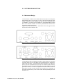
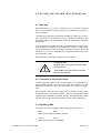
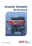
TITAN
Micro
X.21, V.35, 2M, 2M-40dB
Operator Manual
Software Description
A Publication of
AVT Audio Video Technologies GmbH
Nordostpark 12
D-90411 Nürnberg
Telefon
+ 49 911 5271-0
Telefax
+ 49 911 5271-100
Email
[email protected]
Internet
http://www.avt-nbg.de
Printed in Germany, November 2000
© AVT Audio Video Technologies GmbH 2000
All rights reserved. Reproduction in whole or in
parts is prohibited without the written consent of
the copyright owner.
The information contained in this publication is
accurate to the best of AVT knwledge. However,
AVT disclaims any liability resulting from the use
orf this information and reserves the right to make
changes without notice.
Version
2.00 (11/00)
T A B L E
O F
C O N T E N T S
1
Safety __________________________________________ 1-9
1.1
General Safety Requirements________________________ 1-9
1.2
Appearance of the safety instructions __________________ 1-9
1.2.1 Classification of safety instructions ___________________ 1-10
1.2.2 Warning symbols_________________________________ 1-11
2
Introduction ____________________________________ 2-12
3
System Description______________________________ 3-13
3.1
Mechanical Design _______________________________ 3-13
3.2
Functionality ____________________________________ 3-14
3.3
Functionality of the video encoder ___________________ 3-14
3.4
Functionality of the video decoder ___________________ 3-15
3.5
Functionality of the X.21 interface board_______________ 3-15
3.6
Functionality of the V.35 interface board_______________ 3-15
3.7
Functionality of the 2-Mbit/s/T1 interface board _________ 3-16
4
Putting the System into Operation _________________ 4-17
4.1
Mounting _______________________________________ 4-17
4.2
Connection to the mains voltage_____________________ 4-17
4.3
Signalling LEDs__________________________________ 4-17
4.4
Configuration overview ____________________________ 4-18
5
OPERATION with a PC ___________________________ 5-19
5.1
Hardware requirements ___________________________ 5-19
5.2
Connection of the TITAN Micro to the PC ______________ 5-19
5.3
Installation of the software on the PC _________________ 5-19
5.4
Main panel TITAN Micro Commander_________________ 5-20
TITAN Micro X.21, V.35, 2M, 2M-40dB
PAGE 1-5
5.4.1 Main panel TITAN Micro X.21 and V.35 _______________ 5-20
5.4.2 Main panel TITAN Micro 2M ________________________ 5-21
5.5
Menu Configuration_______________________________ 5-23
5.5.1 Sub menu COM Port______________________________ 5-24
5.5.2 Sub menu TITAN Micro____________________________ 5-24
5.5.3 Sub menu Two Button Mode________________________ 5-40
5.5.4 Sub menu System Panel___________________________ 5-40
5.5.5 Sub menu Software Download ______________________ 5-40
5.6
Menu Help______________________________________ 5-41
6
TITAN MICRO 2M DUAL MODE ____________________ 6-43
6.1
Configuration of the TITAN Micro 2M Encoder units______ 6-43
6.2
Configuration of the TITAN Micro Decoder units ________ 6-44
7
INTERFACES ___________________________________ 7-47
7.1
Video interfaces _________________________________ 7-47
7.1.1 Video encoder ___________________________________ 7-47
7.1.2 Video decoder ___________________________________ 7-48
7.1.3 Control interface _________________________________ 7-48
7.2
Alarm interface __________________________________ 7-48
7.3
TTL I/O interface _________________________________ 7-49
7.4
X.21 line interface ________________________________ 7-49
7.5
E1 (2-Mbit/s) line interface _________________________ 7-49
7.5.1 Symmetrical E1 (2-Mbit/s) line interface _______________ 7-50
7.5.2 Unsymmetrical E1 (2-Mbit/s) line interface _____________ 7-50
PAGE 1-6
7.6
T1 line interface__________________________________ 7-50
7.7
V.35 line interface ________________________________ 7-51
8
Remote Control functions ________________________ 8-52
8.1
Remote Configuration of the Encoder_________________ 8-52
8.2
Transmission of the Decoder TTL Input _______________ 8-52
8.3
Data Channel ___________________________________ 8-53
9
Configuration of the alarm interface ________________ 9-54
10
TROUBLE Shooting ____________________________ 10-55
TITAN Micro X.21, V.35, 2M, 2M-40dB
TITAN Micro X.21, V.35, 2M, 2M-40dB
PAGE 1-7
PAGE 1-8
TITAN Micro X.21, V.35, 2M, 2M-40dB
1 SAFETY
The unit described is designed against the latest technical parameters and
complies with all national and international safety requirements. It operates
with a high level of operational safety resulting from long development experience and stringent quality control in our company.
In normal operation this equipment is safe.
There are, however, some potential sources of danger that cannot be completely eliminated.
This Operator Manual therefore contains basic safety instructions that must be
observed during system configuration and operation. This Operator Manual
must be read before the system is used and the current version of the document must always be kept close to the equipment.
All safety instructions have a uniform appearance. This appearance is described in detail in CHAP. 1.2 .
1.1 General Safety Requirements
In order to keep the technically unavoidable residual risk to a minimum, it is
imperative to observe the following rules:
•
Transport, storage and operation of the unit/system must be under the
permissible conditions only.
•
Installation, configuration and disassembly must be carried out only by expert personnel and with reference to the respective documentation.
•
The system must be operated by expert and authorised users only.
•
The system must not be operated unless it is in perfect working order.
•
Any conversions or changes to the system or parts of the system (including the software) must be carried out by qualified personnel from our company or by expert personnel authorised by our company.
All changes carried out by other persons lead to a complete exemption
from liability.
•
The removal or disabling of safety facilities, the clearing of faults and errors, and the maintenance of the equipment must be carried out by specially qualified personnel only.
•
Non-system software is used at one´s own risk. The use/installation of
non-system software can adversely affect the normal functioning of the
system software.
•
Only use tested and virus-free data carriers!
1.2 Appearance of the safety instructions
All safety instructions include a signal word that classifies the danger and a
text block that contains descriptions of the type and cause of the danger, the
consequences of ignoring the safety instruction and the measures that can be
TITAN Micro X.21, V.35, 2M, 2M-40dB
PAGE 1-9
taken to minimise the danger. In some safety instructions, a warning symbol is
placed underneath the signal word (see also CHAP. 1.2.2):
Signal word
Type and cause of danger
Possible Consequences of ignoring the safety instruction
!
Measures to minimise the danger
1.2.1 Classification of safety instructions
There are five classes of safety instructions: "Danger", "Warning", "Caution",
"Notice" and "Important". The classification is shown in the following table.
Death
Serious injury
1
Minor injury
2
Fault
Material damage
Result
Signal word
d
l
p
d
l
p
d
l
p
d
l
p
d
l
p
e
i
o
e
i
o
e
i
o
e
i
o
e
i
f
k
s
f
k
s
f
k
s
f
k
s
f
k
o
s
s
i
e
s
i
e
s
i
e
s
i
e
s
i
e
n
l
i
n
l
i
n
l
i
n
l
i
n
l
i
i
y
b
i
y
b
i
y
b
i
y
b
i
y
b
t
l
t
l
t
l
t
l
t
l
e
e
e
e
e
e
e
e
e
e
3
DANGER
WARNiNG
CAUTION
NOTICE
IMPORTANT
The signal word "Note" is also used in the Operator Manual. Text passages
marked in this way do not describe a danger, but rather contain reminders,
tips and general information to ensure optimum operation of the system.
PAGE 1-10
1
Damage to product or product environment
2
Considerable impairment to operation
3
This danger class is not required for TITAN Micro
TITAN Micro X.21, V.35, 2M, 2M-40dB
1.2.2 Warning symbols
The following warning symbols are used:
Symbol
!
Meaning
General warning about a danger
Warning about a dangerous electrical voltage
The safety instructions classified "Danger", "Warning" and "Caution" always
include a warning symbol. "Notice" and "Important" safety instructions sometimes include a warning symbol.
TITAN Micro X.21, V.35, 2M, 2M-40dB
PAGE 1-11
2
INTRODUCTION
The TITAN Micro units can be equipped with X.21 or V.35 or 2-Mbit/s Interface units. The TITAN Micro X.21 and V.35 can be used for the transmission
of full-motion pictures at bit rates from 64-kbit/s to 1024-kbit/s in steps of 64kbit/s. TITAN Micro 2M can occupy up to 16 x 64-kbit/s time slots (1024-kbit/s)
of the 30 possible time slots (1920-kbit/s) for coded data of full-motion pictures. In the multi mode a few TITAN Micro 2M units can be daisy chained. In
each TITAN Micro 2M the occupied Time slots must be configured. The used
coding algorithm meets the requirements of ITU-T Recommendation H.261. In
addition TITAN Micro contains 4 x TTL inputs and outputs and also an electrically decoupled input and output.
The TITAN Micro units are designed as an Encoder or Decoder. Both types of
units are described in this Operator Manual.
PAGE 2-12
TITAN Micro X.21, V.35, 2M, 2M-40dB
3 SYSTEM DESCRIPTION
3.1 Mechanical Design
The TITAN Micro consists of two boards which are mounted in a housing with
the dimensions (W x H x D) 182 mm x 57 mm x 165 mm and a plug top power
supply. TITAN Micro can be installed as a table top unit or, using the option
"19" adapter" in 19" racks. The "19" adapter" can be equipped with two TITAN
Micro units. Sufficient ventilation is ensured by ventilation holes located at the
rear and the sides of the housing.
Figure 1 shows the rear view of the TITAN Micro X.21/V.35, Figure 2 shows
the rear view of the TITAN Micro 2M .
Figure 1: Rear view of TITAN Micro X.21/V.35
Figure 2: Rear view of TITAN Micro 2M
The TITAN Micro will be powered by a plug top power supply unit. The plug
top power supply unit of TITAN Micro can be powered with AC voltages between 198V and 264V (nominal voltage range 230-240V). The mains frequency can also vary between 40 and 70 Hz. The maximum power consumption is approx. 38 W. One fan has been built in for cooling purposes. The fan
generates a minimum of noise. The equipment also has 3 LEDs on the front
panel which are used for status indication of the system. The configuration of
the system will be done by a PC via the control Interface (RS232) at the rear
side of the unit.
TITAN Micro X.21, V.35, 2M, 2M-40dB
PAGE 3-13
3.2 Functionality
The TITAN Micro incorporates a video encoder or video decoder and a network interface circuit. The TITAN Micro X.21 is equipped with a X.21 network
interface board. TITAN Micro V.35 incorporates a V.35 network interface
board whereas the TITAN Micro 2M consists of a 2-Mbit/s/T1 network interface board according to ITU-T Rec. G.703/G.704.
Functionality of the basic board:
•
Encoding of full-motion pictures (encoder) according to ITU Rec H.261:
FCIF resolution (Full Common Intermediate Format) has been implemented. This format supports a frame rate of 15 Hz
•
Decoding of full-motion pictures (decoder) according to ITU Rec. H.261
•
4 TTL signal inputs and a electrically decoupled signal input for local control
Functionality of the X.21 network interface board:
•
X.21 network access
•
Generation of data rates of 64-kbit/s ... 1024-kbit/s
Functionality of the V.35 network interface board:
•
V.35 network access
•
Generation of data rates of 64-kbit/s ... 1024-kbit/s
Functionality of the 2-Mbit/s/T1 network interface board:
•
2-Mbit/s/T1 network access according to ITU -T Rec. G.703
•
Multiplexing according to ITU-T Rec. G.704
•
Regeneration of the received network signal and clock generation
•
Regenerator capability with 40dB sensitivity
3.3 Functionality of the video encoder
The video encoder meets the requirements of ITU-T Rec. H.261. The higher
resolution picture format FCIF (Full Common Intermediate Format) has been
implemented. This format is supported up to a frame rate of 15 Hz.
CVBS or Y/C signals can be used as input signals. For CVBS signals, the
video standards PAL and NTSC will be supported. Genlock outputs are provided for the synchronisation of connected cameras.
The sockets for the video inputs of the video encoder TITAN Micro can be assigned to various signal types. There are five video input modes available for
this purpose. These are shown in TABLE 3.1 .
PAGE 3-14
TITAN Micro X.21, V.35, 2M, 2M-40dB
TABLE 3.1 POSSIBLE INPUT SIGNALS FOR THE VIDEO INPUT MODE
CVBS1
CVBS2
CVBS3
CVBS4
Y/C 1
Y/C 2
+
-
-
-
-
-
+
+
+
+
-
-
+
+
-
-
+
-
-
-
+
+
-
+
-
-
-
-
+
+
3.4 Functionality of the video decoder
The video decoder meets also the requirements of ITU-T Rec. H.261. It decodes the picture format FCIF at a maximum frame rate of 15 Hz.
CVBS and Y/C or RGB signals are provided at the output. For the CVBS signal, the video standards PAL and NTSC can be selected. For the video outputs, there are two different modes available. These are shown in TABLE 3.2.
The available Genlock inputs allow a remote synchronisation of the video decoder.
TABLE3.2: POSSIBLE OUTPUT SIGNALS FOR THE VIDEO OUTPUT MODE
CVBS
Y/C
+
+
RGB, Sync.
-
+
-
+
3.5 Functionality of the X.21 interface board
This interface board contains the X.21 interface circuits including transmitter
and receiver components. The X.21 interface is available at the rear side of
the unit. The X.21 interface allows access to transmission networks and is a
data interface with bit clock. The interface can operate from 64-kbit/s up to
1024-kbit/s in 64-kbit/s steps.
This is a DTE (Data Terminal Equipment) interface which requires as a transport medium a line in which the data is switched en bloc.
3.6 Functionality of the V.35 interface board
This interface board contains the V.35 interface circuits including transmitter
and receiver components. The V.35 interface is available at the rear side of
the unit. The V.35 interface allows access to transmission networks and is a
data interface with separate bit clocks for receive and transmit data. The interface can operate from 64-kbit/s up to 1024-kbit/s in 64-kbit/s steps.
This is a DTE (Data Terminal Equipment) interface which requires as a transport medium a line in which the data is switched en bloc.
TITAN Micro X.21, V.35, 2M, 2M-40dB
PAGE 3-15
3.7 Functionality of the 2-Mbit/s/T1 interface board
This interface board contains the complete 2-Mbit/s and T1 interface circuits
including transmitter, receiver and further control components. The signal is
HDB3 coded and complies with ITU-T Rec. G.703. The multiplex structure of
the signal is implemented according to ITU-T Rec. G.704. A multiplex frame
of the 2-Mbit/s signal consists of 32 time slots and a T1 frame of 24 time slots
with a data rate of 64-kbit/s per time slot. Time slot 0 contains alternately the
frame alignment signal and the service digits. The frame alignment signal is
for synchronisation, the service digits transmit alarms to the remote end.
Two different formats have been defined for the 2-Mbit/s data stream:
•
•
the double-frame format
the CRC4-frame format
In the CRC4 -frame format, a so-called check bit is transmitted as the first bit
of the frame alignment word.
16 time slots of the available 30 time slots at E1 or 24 time slots at T1 can be
filled with coded video data.
The TITAN Micro 2M-40dB includes a regenerator circuit with 40 dB sensitivity.
PAGE 3-16
TITAN Micro X.21, V.35, 2M, 2M-40dB
4 PUTTING THE SYSTEM INTO OPERATION
4.1 Mounting
With its dimensions (W x H x D) of 182 mm x 57 mm x 165 mm the TITAN
Micro can be operated as a table-top device or, be inserted into 19" racks using a 19" adapter.
The dimensions given above are valid for the table-top version with no feet. If
the TITAN Micro is to be inserted into a rack, it should be remembered that
the bending radius of the cables should always be greater than the minimum
allowed value.
If the TITAN Micro is installed in a rack, it should also be ensured that sufficient ventilation is provided. It is recommended that at least 1 cm space is left
next to the openings. As rule, the ambient temperature should not lie outside
the range +5°C to +40°C. These limits are of particular importance if the system is inserted in a rack.
During operation, the humidity must lie between 5% and 85%.
NOTICE
!
Incorrect ambient temperature and humidity can lead
to equipment failure
Operation of the unit outside the above limits invalidates the warranty.
The TITAN Micro X.21 must therefore be operated
within the specified limits.
4.2 Connection to the mains voltage
The plug top power supply unit of the TITAN Micro can be operated with a
voltage (mains) between 198 V and 264 V. The mains frequency can vary
between 40 Hz and 70 Hz. The power consumption is a maximum of approx.
35 W.
After putting the plug top power supply unit into operation, all three LEDs
should light up for a time period of approx. 1 second. A internal reset is then
triggered. This is indicated by switched off LEDs. After approximately twenty
seconds, the unit is operational and the green "Power" LED should light up.
4.3 Signalling LEDs
There are three LEDs for signalling on the TITAN Micro (see Figure 3):
•
Power
green
Lights up when system is ready for operation.
•
Connect
yellow
Lights up if a connection is established.
TITAN Micro X.21, V.35, 2M, 2M-40dB
PAGE 4-17
•
Alarm:
red
Lights up if a fault has occurred in the unit.
Figure 3: Front view of TITAN Micro
4.4 Configuration overview
This chapter shall give an overview of the configuration of the system. Detailed instructions are described in the following chapters.
1. Connection of a video source to the video encoder and of monitors to the
video decoder
2. Connection of the unit to the transmission network (X.21, V.35 or 2-Mbit/s
or T1)
3. Loading of the Windows application software „TITAN Micro“ (see chapter.
5.3) and configuration of the PC (see chapter 5.5.1)
4. Configuration of the video encoder
5. Configuration of the video decoder
6. Entering of a "connect" command via PC to the Video encoder or video
decoder.
7. Checking the establishing of the connection.
PAGE 4-18
TITAN Micro X.21, V.35, 2M, 2M-40dB
5 OPERATION WITH A PC
The Windows control software „TITAN Micro“ allows a simple configuration
and control of the system .
5.1 Hardware requirements
The PC must fulfil the following minimum requirements:
•
IBM PC AT, IBM PS/2 or 100% compatible
•
Windows 3.1/Windows 95
•
approx. 600 kByte free conventional memory
•
approx. 1,5 MB free hard-disk memory
•
IBM VGA graphics board (display adapter) with 800 x 600 pixels
•
a free serial interface RS-232
•
Microsoft, IBM PS/2 or 100% software-compatible mouse
5.2 Connection of the TITAN Micro to the PC
Connect the PC serial interface to the CONTROL (RS232C) interface on the
rear panel of the TITAN Micro. Use the delivered cable (8-pin Mini DIN to 9pin D-Submin cable).
The serial interface of TITAN Micro (RS232C) is configured in accordance
with the following parameters by the factory:
•
String Commands
•
19200 Baud
•
8 data bits
•
no parity
The TITAN Micro can now be controlled from the PC.
5.3 Installation of the software on the PC
For the installation 1 of the software on the PC, please place the disk in the
drive of the PC. Then start the installation under Windows 95 by selecting the
START button and selecting the sub menu item Ausführen.... Insert into the
command line
a:setup
and select OK button. If your disk drive is not "a", use the corresponding designation in place of "a", Now follow the remarks of the installation program and
use the recommended directory. As proposed please install a new program
1
Please make a backup copy of the original disk before installation.
TITAN Micro X.21, V.35, 2M, 2M-40dB
PAGE 5-19
group „Titan Micro“. In this program group you will find later the symbol for
starting the program as well as a possibility for de-installation of the program.
After successful installation you will find now under START → PROGRAMME
→TITAN Micro: program symbol
software.
For de-installation select
the
for starting the TITAN Micro
symbol
5.4 Main panel TITAN Micro Commander
After starting the software the user will get displayed the main panel. Depending on the connected TITAN Micro unit (TITAN Micro X.21 or TITAN Micro V.35 or TITAN Micro 2M and Encoder or Decoder) different graphical user
interfaces will be displayed.
5.4.1 Main panel TITAN Micro X.21 and V.35
All necessary settings for encoder and decoder will be indicated in different
panels. The difference between the TITAN Micro X.21 and TITAN Micro V.35
panels is only the display of the product name.
5.4.1.1 Main panel TITAN Micro X.21/V.35 Encoder
Figure 4: Main panel TITAN Micro X.21/V.35 Encoder
•
PAGE 5-20
The Control field contains the status of the connection
TITAN Micro X.21, V.35, 2M, 2M-40dB
•
The field Video Source displays the selected video source. With the down
arrow the video source can be selected.
•
Connect or Disconnect button for connecting and disconnecting to the
network.
•
LSD channel is a unidirectional data channel from decoder to encoder.
•
Video Rate describes the X.21 or V.35 data rate
5.4.1.2 Main panel TITAN Micro X.21/V.35 Decoder
Figure 5: Main panel TITAN Micro X.21/V.35 Decoder
•
The Control Field contains the status of the connection
•
The field Video Source displays the selected video source. With the down
arrow the video source can be selected.
•
Connect or Disconnect Button for connecting and disconnecting to the
network.
•
LSD channel is a unidirectional data channel from decoder to encoder.
5.4.2 Main panel TITAN Micro 2M
In addition to the configuration parameters of the encoder and decoder also
the 2-Mbit/s/T1 line alarms will be indicated.
The following are displayed:
• Signal
connection exists
• Sync
system is synchronised
• AIS
AIS signal received
• Clock
external clock signal received
• Local N-Alarm
local deferred maintenance (non-urgent) alarm
• Local D-Alarm
local prompt maintenance (urgent) alarm
• Remote N-Alarm
deferred alarm on the remote side
• Remote D-Alarm
prompt alarm on the remote side
TITAN Micro X.21, V.35, 2M, 2M-40dB
PAGE 5-21
5.4.2.1 Main panel TITAN Micro 2M Encoder
Figure 6: Main panel TITAN Micro 2M Encoder
PAGE 5-22
•
The Control Field contains the status of the connection
•
The field Video Source displays the selected video source. With the down
arrow the video source can be selected.
•
Video Rate describes the number of used time slots.
•
Connect or Disconnect Button for connecting and disconnecting to the
network.
•
LSD channel is a bi-directional data channel between decoder and encoder.
•
The Alarms Field shows the 2-Mbit/s/T1 alarm messages
TITAN Micro X.21, V.35, 2M, 2M-40dB
5.4.2.2 Main panel TITAN Micro 2M Decoder
Figure 7: Main panel TITAN Micro 2M Decoder
•
The Control Field contains the status of the connection
•
The field Video Source displays the selected video source. With the down
arrow the video source can be selected.
•
Video Rate describes the number of used time slots.
•
Connect or Disconnect Button for connecting and disconnecting to the
network.
•
LSD channel is a unidirectional data channel from decoder to encoder.
•
The Alarms Field shows the 2-Mbit/s/T1 alarm messages
5.5 Menu Configuration
After selection of the menu item Configuration the choices for the configuration of the system will be displayed. Selected can be
• COM Port
•
Titan Micro (X.21 or V.35 or 2M or T1 automatic via hardware configuration)
•
Two Button Mode
•
System Panel
TITAN Micro X.21, V.35, 2M, 2M-40dB
PAGE 5-23
•
Software Download
5.5.1 Sub menu COM Port
After selection of the sub menu item COM-Port a window for the selection
and configuration of the COM interface of the PC opens. If the selected COM
port is already occupied an error message will be displayed. Then select another open COM port. For the Baud rate always select 19200 Baud.
Figure 8: Sub menu COM-Port
5.5.2 Sub menu TITAN Micro
In the sub menu TITAN Micro the units TITAN Micro X.21 , V.35 or TITAN
Micro 2M can be configured. Dependent on the equipped interface board of
TITAN Micro the sub menus of TITAN Micro X.21 or TITAN Micro V.35 or TITAN Micro 2M will be automatically displayed. There are separate menu items
for encoder and decoder of TITAN Micro.
5.5.2.1 Sub menu TITAN Micro X.21 and V.35 Encoder
There can be displayed 3 different panels: Video, Data and Line.
The configuration will be saved selecting the button "Save on Board".
The commands "Set" and "OK" only cause the transmission of the configuration from the PC to the TITAN Micro but does not store the configuration on
the TITAN Micro. The command "OK" also closes the window of the PC software.
If the "Auto Connect" button is selected the system will automatic reconnect after power failure and power return
5.5.2.1.1 Sub Menu TITAN Micro X.21 and V.35 Enc., Video
Panel
The video inputs can be configured (CVBS 1...4 or Y/C 1, 2) and the actual
video source (Current Video Source) can be set as one of the configured
video inputs. Further the quality of the coded video picture can be defined
(sharpness versus motion). The video standard can be selected as PAL or
NTSC.
PAGE 5-24
TITAN Micro X.21, V.35, 2M, 2M-40dB
Figure 9:Sub menu TITAN Micro X.21/V.35 Enc., Video Panel
5.5.2.1.2 Sub Menu TITAN Micro X.21 and V.35 Enc., Data
Panel
The TTL interface can be configured in 4 different modes for local and remote
control capability. For this purpose the following settings of the "TTL I/O
Mode" field are possible: "off" (no function), "transparent" (allows the remote
control capability from the decoder) , "CVBS select" (local control of the CVBS
camera inputs via Pin 1 and 2) or "Y/C select" (local control of the Y/C camera
inputs via Pin 1) and "CVBS select, connect via TTL in 3" ( in addition to the
local control of the CVBS camera inputs via Pin 1 and 2, connect and disconnect of the line via TTL Pin 3).
TITAN Micro X.21, V.35, 2M, 2M-40dB
PAGE 5-25
Figure 10: Sub menu TITAN Micro X.21/V.35 Enc., Data Panel
5.5.2.1.3 Sub Menu TITAN Micro X.21 and V.35 Enc., Line
Panel
In this sub menu the data rate of the encoder can be set. This selected data
rate has to be identical with the X.21 and V.35 data rate. Data rates of (1 ...
16) x 64-kbit/s can be chosen. If the value “Auto” is selected, the unit measures the clock at the X.21 or V.35 interface and adapts automatically to the received data rate.
If the "Auto Connect" button is selected the system will automatic reconnect after power failure and power return
PAGE 5-26
TITAN Micro X.21, V.35, 2M, 2M-40dB
Figure 11: Sub menu TITAN Micro X.21/V.35 Enc.,Line Panel
5.5.2.2 Sub menu TITAN Micro X.21 and V.35 Decoder
There can be displayed 4 different panels: Video, Data, Line and OSD.
The configuration will be saved selecting the button "Save on Board".
The commands "Set" and "OK" only cause the transmission of the configuration from the PC to the TITAN Micro but does not store the configuration on
the TITAN Micro. The command "OK" also closes the window of the PC software.
If the "Auto Connect" button is selected the system will automatic reconnect after power failure and power return
5.5.2.2.1 Sub menu TITAN Micro X.21/V.35 Dec., Video Panel
The video output combinations Y/C+CVBS or RGBSyn+CVBS can be selected. Via remote control the video inputs of the Encoder can be configured
(CVBS 1...4 or Y/C 1, 2) and the quality of the coded video picture can be defined (sharpness versus motion). The video standard can be selected as PAL
or NTSC. The camera inputs can be switched in a cyclic mode activating the
field “Cyclic Camera Switch”. The switching period can be defined in field
“Switch Time”.
TITAN Micro X.21, V.35, 2M, 2M-40dB
PAGE 5-27
Figure 12: Sub menu TITAN Micro X.21/V.35 Dec., Video Panel
5.5.2.2.2 Sub menu TITAN Micro X.21 and V.35 Dec., Data
Panel
The LSD data rate of the unidirectional data channel in the direction from decoder → encoder can be set. Available data rates are 1200 Baud, 2400 Baud,
4800 Baud or 9600 Baud. The TTL interface can be configured in 4 different
modes for remote control of the Encoder. For this purpose the following settings of the "TTL I/O Mode" field are possible: "off" (no function), "transparent"
(transparent transmission of the status of the TTL inputs at the Decoder to the
Encoder), "CVBS select" (remote control of the CVBS camera inputs via Pin 1
and 2) or "Y/C select" (remote control of the Y/C camera inputs via Pin 1) and
"CVBS select, connect via TTL in 3" ( in addition to the remote control of the
CVBS camera inputs via Pin 1 and 2, local connect and disconnect of the line
via TTL Pin 3).
PAGE 5-28
TITAN Micro X.21, V.35, 2M, 2M-40dB
Figure 13: Sub menu TITAN Micro X.21/V.35 Dec., Data Panel
5.5.2.2.3 Sub menu TITAN Micro X.21 and V.35 Dec., Line
Panel
If the "Auto Connect" button is selected the system will automatic reconnect
after power failure and power return.
TITAN Micro X.21, V.35, 2M, 2M-40dB
PAGE 5-29
Figure 14: Sub menu TITAN Micro X.21/V.35 Dec. Line Panel
5.5.2.2.4 Sub menu TITAN Micro X.21 and V.35 Dec., OSD
Panel
Field "Time/Date" allows the selection of the clock function and also the setting of the clock. In the field “OSD Mode” fixed symbols and self defined characters for the selected camera can be displayed in the decoded picture. Also
strings can be defined by the user and can be indicated in the decoded picture.
PAGE 5-30
TITAN Micro X.21, V.35, 2M, 2M-40dB
Figure 15: Sub menu TITAN Micro X.21/V.35 Dec., OSD Panel
5.5.2.3 Sub menu TITAN Micro 2M, Encoder
There can be displayed 3 different panels: Video, Data and Line.
The configuration will be saved selecting the button "Save on Board".
The commands "Set" and "OK" only cause the transmission of the configuration from the PC to the TITAN Micro but does not store the configuration on
the TITAN Micro. The command "OK" also closes the window of the PC software.
If the "Auto Connect" button is selected the system will automatic reconnect after power failure and power return
5.5.2.3.1 Sub menu TITAN Micro 2M Enc., Video Panel
The video inputs can be configured (CVBS 1...4 or Y/C 1, 2) and the actual
video source (Current Video Source) can be set as one of the configured
video inputs. Further the quality of the coded video picture can be defined
(sharpness versus motion). The video standard can be selected as PAL or
NTSC.
TITAN Micro X.21, V.35, 2M, 2M-40dB
PAGE 5-31
Figure 16: Sub menu TITAN Micro 2M Enc., Video Panel
5.5.2.3.2 Sub menu TITAN Micro 2M Enc., Data Panel
The TTL interface can be configured in 4 different modes for local and remote
control capability. For this purpose the following settings of the "TTL I/O
Mode" field are possible: "off" (no function), "transparent" (allows the remote
control capability from the decoder) , "CVBS select" (local control of the CVBS
camera inputs via Pin 1 and 2) or "Y/C select" (local control of the Y/C camera
inputs via Pin 1) and "CVBS select, connect via TTL in 3" ( in addition to the
local control of the CVBS camera inputs via Pin 1 and 2, connect and disconnect of the line via TTL Pin 3).
PAGE 5-32
TITAN Micro X.21, V.35, 2M, 2M-40dB
Figure 17: Sub menu TITAN Micro 2M Enc., Data Panel
5.5.2.3.3 Sub menu TITAN Micro 2M Enc., Line Panel
In this sub menu the data rate of the encoder can be set and the time slot for
the bi-directional control channel has to be defined. Data rates of (1 ... 16) x
64-kbit/s can be chosen. To define the data rate the number of the first time
slot and the number of time slots used for the video signal must be set. The
coded video data can occupy 16 time slots of the 2-Mbit/s/T1 signal. The operating modes “Standard” and “Data+Crtl insert” should be selected. As address number 0 should be set. As a further item the interface parameters can
be selected.
If the "Auto Connect" button is selected the system will automatic reconnect
after power failure and power return.
TITAN Micro X.21, V.35, 2M, 2M-40dB
PAGE 5-33
Figure 18: Sub menu TITAN Micro 2M Enc., Line Panel, E1
PAGE 5-34
TITAN Micro X.21, V.35, 2M, 2M-40dB
Figure 19: Sub menu TITAN Micro 2M Enc., Line Panel, T1
5.5.2.4 Sub menu TITAN Micro 2M Decoder
There can be displayed 4 different panels: Video, Data, Line and OSD.
The configuration will be saved selecting the button "Save on Board".
The commands "Set" and "OK" only cause the transmission of the configuration from the PC to the TITAN Micro but does not store the configuration on
the TITAN Micro. The command "OK" also closes the window of the PC software.
If the "Auto Connect" button is selected the system will automatic reconnect after power failure and power return
5.5.2.4.1 Sub menu TITAN Micro 2M Dec., Video Panel
The video output combinations Y/C+CVBS or RGBSyn+CVBS can be selected. Via remote control the video inputs of the Encoder can be configured
(CVBS 1...4 or Y/C 1, 2) and the quality of the coded video picture can be defined (sharpness versus motion). The video standard can be selected as PAL
or NTSC. The camera inputs can be switched in a cyclic mode activating the
field “Cyclic Camera Switch”. The switching period can be defined in field
“Switch Time”.
TITAN Micro X.21, V.35, 2M, 2M-40dB
PAGE 5-35
Figure 20: Sub menu TITAN Micro 2M Dec., Video Panel
5.5.2.4.2 Sub menu TITAN Micro 2M Dec., Data Panel
The LSD data rate of the bi-directional data channel between the decoder and
encoder can be set. Available data rates are 1200 Baud, 2400 Baud, 4800
Baud or 9600 Baud. The TTL interface can be configured in 4 different modes
for remote control of the Encoder. For this purpose the following settings of
the "TTL I/O Mode" field are possible: "off" (no function), "transparent" (transparent transmission of the status of the TTL inputs at the Decoder to the Encoder), "CVBS select" (remote control of the CVBS camera inputs via Pin 1
and 2) or "Y/C select" (remote control of the Y/C camera inputs via Pin 1) and
"CVBS select, connect via TTL in 3" ( in addition to the remote control of the
CVBS camera inputs via Pin 1 and 2, local connect and disconnect of the line
via TTL Pin 3).
PAGE 5-36
TITAN Micro X.21, V.35, 2M, 2M-40dB
Figure 21: Sub menu TITAN Micro 2M Dec., Data Panel
5.5.2.4.3 Sub menu TITAN Micro 2M Dec., Line Panel
In this sub menu the data rate of the encoder can be set and the time slot for
the bi-directional control channel has to be defined. Data rates of (1 ... 16) x
64-kbit/s can be chosen. To define the data rate the number of the first time
slot and the number of time slots used for the video signal must be set. The
coded video data can occupy 16 time slots of the 2-Mbit/s/T1 signal. The operating modes “Standard” and “Data+Crtl insert” should be selected. As address number 0 should be set.
Remark:
The configuration of the decoder has to be the same as of the encoder.
As a further item the interface parameters can be selected.
If the "Auto Connect" button is selected the system will automatic reconnect
after power failure and power return.
TITAN Micro X.21, V.35, 2M, 2M-40dB
PAGE 5-37
Figure 22: Sub menu TITAN Micro 2M Dec., Line Panel, E1
PAGE 5-38
TITAN Micro X.21, V.35, 2M, 2M-40dB
Figure 23: Sub menu TITAN Micro 2M Dec., Line Panel, T1
5.5.2.4.4 Sub menu TITAN Micro 2M Dec., OSD Panel
Field "Time/Date" allows the selection of the clock function and also the setting of the clock. In the field “OSD Mode” fixed symbols and self defined characters for the selected camera can be displayed in the decoded picture. Also
strings can be defined by the user and can be indicated in the decoded picture.
TITAN Micro X.21, V.35, 2M, 2M-40dB
PAGE 5-39
Figure 24: Sub menu TITAN Micro 2M Dec., OSD Panel
5.5.3 Sub menu Two Button Mode
Via selection of this command the items Connect and Disconnect can be configured as one or two button display.
5.5.4 Sub menu System Panel
The sub menu System Panel allows simple communication with TITAN Micro.
For control purpose string commands can be entered.
5.5.5 Sub menu Software Download
The sub menu Software Download is used to copy new software from the PC
to the TITAN Micro units.
After selection of the sub menu in the field "Ctl File Name" one of the following
software packages will be displayed in accordance to the stored software:
• MDSP.CTL
Processor Software: Empty, no software stored
• MWENC.CTL
Encoder Software: Encoder software stored
• MWDEC.CTL
Decoder Software: Decoder Software stored
The button "Browse" allows the selection of the drives of the files for the
software download.
Start the transmission of the software to the TITAN Micro by selecting the
button "Start Download". During the software download a few files will be upPAGE 5-40
TITAN Micro X.21, V.35, 2M, 2M-40dB
dated whereas the command "Current File" indicates how much of the software of the actual file has been loaded and the command "All" indicates how
much of the software of the complete number of files has been loaded. In the
white area remarks will be indicated in relation to the stored files. The button
"OK" closes the window.
Figure 25: Sub menu Software Download
5.6 Menu Help
Company address and installed software version will be indicated in the menu
help.
TITAN Micro X.21, V.35, 2M, 2M-40dB
PAGE 5-41
Figure 26: Sub menu Help
PAGE 5-42
TITAN Micro X.21, V.35, 2M, 2M-40dB
6 TITAN MICRO 2M DUAL MODE
To use the complete capacity of the 2-Mbit/s data stream, it is possible to interconnect two TITAN Micro 2M units in a daisy chain mode. The 2-Mbit/s signal of the first TITAN Micro 2M can be routed through the second TITAN Micro 2M.
Each TITAN Micro 2M consists of an individual bi-directional data channel for
e.g. remote camera control.
6.1 Configuration of the TITAN Micro 2M Encoder units
In the following the line panels of the two TITAN Micro 2M Encoder 1 and 2
are described. The time slot allocation of both units is described in the two
line panels. In the case there is used a synchronous network also Encoder 1
must be set to „Clock Source“ „Recovered“.
Figure 27: Sub menu TITAN Micro 2M Enc.1, Line Panel
TITAN Micro X.21, V.35, 2M, 2M-40dB
PAGE 6-43
Figure 28: Sub menu TITAN Micro 2M Enc.2, Line Panel
6.2 Configuration of the TITAN Micro Decoder units
In the following the line panels of the two TITAN Micro 2M Decoder 1 and 2
are described. The time slot allocation of both units is described in the two
line panels.
Remark:
The configuration of the decoder units must be the same as of the encoder units.
PAGE 6-44
TITAN Micro X.21, V.35, 2M, 2M-40dB
Figure 29: Sub menu TITAN Micro 2M Dec.1, Line Panel
TITAN Micro X.21, V.35, 2M, 2M-40dB
PAGE 6-45
Figure 30: Sub menu TITAN Micro 2M Dec.2, Line Panel
PAGE 6-46
TITAN Micro X.21, V.35, 2M, 2M-40dB
7 INTERFACES
The connectors of the interfaces are at the rear side of the unit.
Figure 31: Rear view of TITAN Micro X.21/V.35
Figure 32: Rear view of TITAN Micro 2M
7.1 Video interfaces
TITAN Micro contains of 2 connectors for its video interfaces, a BNC socket
and a 15 pin D-Submin socket with 3 rows (VGA socket).
7.1.1 Video encoder
The video inputs are configurable in five modes. One socket is assigned to
different signals, depending on the mode. The socket assignment for the various modes is shown in TABLE 6.1.
TABLE 6.1: VIDEO INPUTS
CVBS (BNC)
VIDEO (D SubMIn)
CVBS
Pin 1
Pin 2
Pin 3
Pin 4
Pin 5
Pin 6 ...10
Pin 11
CVBS1
-
-
-
-
nc
GND
+12V
CVBS 1
-
CVBS3
CVBS2
CVBS4
nc
GND
+12V
+12V
-
CVBS1
CVBS3
CVBS2
CVBS4
nc
GND
CVBS1
-
Y1
CVBS2
C1
nc
GND
+12V
-
CVBS1
Y1
CVBS2
C1
nc
GND
+12V
-
Y2
CVBS3
C2
CVBS4
nc
GND
+12V
-
Y2
Y1
C2
C1
nc
GND
+12V
TITAN Micro X.21, V.35, 2M, 2M-40dB
PAGE 7-47
TITAN Micro offers in addition to the video inputs 4 Genlock outputs which are
available on pins 12 ... 15 ( Genlock 1 ...4) of socket " VIDEO".
7.1.2 Video decoder
The video decoder contains of a CVBS, Y/C or RGB interface with separate
Sync. The socket assignment for the two modes is shown in TABLE 6.2.
TABLE 6.2: VIDEO OUTPUTS
CVBS(BNC)
CVBS
VIDEO (D Sub Min)
Pin 1
Pin 2
Pin 3
Pin 4
Pin 5
Pin 6
Pin 11
Pin
...10
12,15
CVBS
-
Y
-
C
-
GND
+12V
-
CVBS
Y
-
C
-
GND
+12V
nc
nc
CVBS
-
G
B
R
Sync
GND
+12V
nc
-
CVBS
G
B
R
Sync
GND
+12V
nc
The video decoder offers also a Genlock input and output.
The Genlock input is available at pin 13 of socket "VIDEO" and the Genlock
output is available at pin 14 of socket "VIDEO".
Remark:
The Genlock inputs and outputs as well as the video outputs Y/C and RGB
Sync are not available in software version1.0.
7.1.3 Control interface
For the Control interface there is a PC adapter cable included in the delivery.
The socket assignment of the 8 pin Mini DIN socket is shown inTABLE 6.3.
TABLE 6.3: CONTROL INTERFACE
Pin
Funcion
1
2
3
4
5
6
7
8
nc
nc
DAT
GND
DAT
nc
CTL
CTL
RxD
TxD
RxD
TxD
7.2 Alarm interface
To the socket "ALARMS" there can be connected or delivered alarm signals.
The socket assignment of the 8 pin Mini DIN socket is shown in TABLE 6.4 .
TABLE 6.4: ALARMS
Pin
Function
PAGE 7-48
1
2
3
4
5
6
7
GND
+5V
Alarm
TTL
Alarm
Alarm
Alarm
TTL
out
in 4
in +
out
in -
out 4
•
Alarm out : pin 3 to pin 6 connected, if an alarm is delivered
(electrically decoupled contact)
•
Alarm in : +5V between pin 5 and pin 7
8
TITAN Micro X.21, V.35, 2M, 2M-40dB
7.3 TTL I/O interface
The socket TTL I/O allows the connection of TTL signals and also TTL signals can be delivered. The socket assignment of the 8 pin Mini DIN socket is
shown in TABLE 6.5.
TABLE 6.5: TTL I/O
Pin
Function
1
2
3
4
5
6
7
8
GND
+5V
TTL
TTL
TTL
TTL
TTL
TTL
in 1
in 2
in 3
out 1
out 2
out 3
7.4 X.21 line interface
The X.21 interface is labelled with "X.21" . It is implemented as a DTE. The
pin assignment of the connector is shown in TABLE 6.6.
TABLE 6.6: X.21 LINE INTERFACE
Connect.
Signal
Description
Characteristic
1
SHIELD
Shield
Type:
DTE
2
Ta
Transmit a
Level:
V.11,
3
Ca
Control a
4
Ra
Receive a
5
Ia
Indicate a
6
Sa
Signal Element Timing a
7
Ba
not connected
8
GND
Ground
9
Tb
Transmit b
10
Cb
Control b
11
Rb
Receive b
12
Ib
Indicate b
13
Sb
Signal Element Timing b
14
Bb
not connected
15
sym-
metrical
Data rate:
64 till
1024- kbit/s
Range
100 m
not used
7.5 E1 (2-Mbit/s) line interface
The E1 (2-Mbit/s) line interface can be configured as 120 Ohm symmetrical or
75 Ohm unsymmetrical interface. The selection has to be done via jumpers (
11jumper) on the E1/T1 line interface board:
- 120 Ohm symmetrical:
all 11 jumpers in position to the internal
connectors
- 75 Ohm unsymmetrical: all 11 jumpers in the middle position
The TITAN Micro 2M-40dB Encoder Decoder units consist of a special E1
(2-Mbit/s) line interface circuit where a 6dB or 40dB level interface can be
chosen. The selection can be done by a further row of jumpers (4 jumpers) on
the E1/T1 line interface board:
- 6 dB level:
- 40 dB level:
TITAN Micro X.21, V.35, 2M, 2M-40dB
all 4 jumpers in position to the internal
connectors
all 4 jumpers in position to the external
connectors
PAGE 7-49
7.5.1 Symmetrical E1 (2-Mbit/s) line interface
The 120 Ohm symmetrical E1 (2-Mbit/s) line interface is available at a 9 pin
SUB-D socket, which is labelled with "E1/T1 SYM.". The pin assignment of the
socket is shown in TABLE 6.7.
TABLE 6.7: E1 (2-Mbit/s) LINE INTERFACE symmetrical
Connect.
Signal
Description
Electrical characteristics
1
Shield
Shield
Amplitude:
2
RXD a
Data in a
3
TXD a
Data out a
Impedance:
4
RXCLK a
Clock in a
Range
5
TXCLKa
Clock out a
at 6dB level:
100 m
6
RXD b
Data in b
at 40 dB level:
2000 m
7
TXDb
Data out b
Clock amplitude
8
RXCLKb
Clock in b
Input:
0,5 till 1,9 Vop
9
TXCLKb
Clock out b
Output:
1,5 Vop
3 Vss according
to G.703
120 Ohm sym.
7.5.2 Unsymmetrical E1 (2-Mbit/s) line interface
The 75 Ohm unsymmetrical E1 (2-Mbit/s) line interface is labelled with "E1
UNSYM." and available at 3 BNC sockets.
TABLE 6.8: E1 (2-Mbit/s) LINE INTERFACE, BNC socket " DATA IN"
Connect.
Signal
Electrical characteristics
1 (inner conductor)
Data F1 in
Amplitude:
3 Vss as perG.703
2 (outer conductor)
GND
Impedance:
75 Ohm unsym.
Range
at 6dB level:
100 m
at 40 dB level:
2000 m
TABLE 6.9: E1 (2-Mbit/s) LINE INTERFACE, BNC Socket " DATA OUT"
Connect.
Signal
Electrical characteristics
1 (inner conductor)
Data F1 Out
Amplitude:
3 Vss as per G.703
2 (outer conductor)
GND
Impedance:
75 Ohm unsym.
Range
at 6dB level:
100 m
at 40 dB level:
2000 m
TABLE 6.10: E1 (2-Mbit/s) LINE INTERFACE, BNC Socket " CLOCK IN"
Connect.
Signal
Electrical characteristics
1 (inner conductor)
Data T3 In
Amplitude:
2 (outer conductor)
GND
Impedance:
75 Ohm unsym.
Range:
100 m
0,5 till 1,9 Vop
7.6 T1 line interface
The T1 (1,544-Mbit/s) line interface exists only as a 100 Ohm symmetrical interface. The selection of the T1 line interface has to be done by jumpers (11
jumpers) on the E1/T1 line interface:
PAGE 7-50
TITAN Micro X.21, V.35, 2M, 2M-40dB
- T1, 100 Ohm symmetrical:
all 11 jumpers in position to the external
connectors
The 100 Ohm symmetrical T1 (1,544-Mbit/s) line interface is available at a 9
pin SUB-D socket, which is labelled with "E1/T1 SYM. The pin assignment of
the socket is shown in TABLE 6.11.
TABLE 6.11: T1 (1,544-Mbit/s) LINE INTERFACE symmetrical
Connect.
Signal
Description
Electrical characteristics
1
Shield
Shield
Amplitude:
2
RXD a
Data in a
3
TXD a
Data out a
Impedance:
4
RXCLK a
Clock in a
Range
5
TXCLKa
Clock out a
at 6dB level:
100 m
6
RXD b
Data in b
at 40 dB level:
2000 m
7
TXDb
Data out b
Clock amplitude
8
RXCLKb
Clock in b
Input:
0,5 till 1,9 Vop
9
TXCLKb
Clock out b
Output:
1,5 Vop
3 Vss as per
G.703
100 Ohm sym.
7.7 V.35 line interface
The V.35 interface is labelled with "V.35" . It is implemented as a DTE. The
pin assignment of the connector is shown in TABLE 6.12.
TABLE 6.12: V.35 LINE INTERFACE
Connect.
Signal
Description
Characteristic
1
SHIELD
Shield
Type:
DTE
2
TxA
Transmit A
Level:
V.11,
3
TxB
Transmit B
4
TxClkA
Transmit Clock A
5
TxClkB
Transmit Clock B
6
DCD
Data Carrier Detect (in)
7
GND
Ground
8
64 till
1024- kbit/s
Range
100 m
not used
10
RTS
Ready to send (output)
11
RxClkB
Receive Clock B
12
RxClkA
Receive Clock A
13
RxB
Receive B
14
RxA
Receive A
TITAN Micro X.21, V.35, 2M, 2M-40dB
Data rate:
not used
9
15
sym-
metrical
not used
PAGE 7-51
8 REMOTE CONTROL FUNCTIONS
The TITAN Micro Encoder unit can be remotely configured from the Decoder
unit over the line connection back channel (X.21 or V.35 or 2-Mbit/s). Further,
the settings of the TTL inputs at the Decoder can be transmitted to the Encoder where they are available as switching functions. Additionally, a transparent, uni-directional data channel in the X.21 and V.35 units or a bidirectional data channel in the 2M units is available.
8.1 Remote Configuration of the Encoder
Using Windows PC software, the following functions can be remotely controlled from the Decoder over the line connection back channel.
• Selection of camera source for the Encoder (CVBS1 ... CVBS4, or Y/C1,
Y/C2). For this, the camera source is configured in the "Available Video
Sources" field of the video panel. The camera selection can be made from
the Main Menu panel.
CAUTION: The same configuration of the video sources in the "Available
Video Sources" field of the video panel in the Encoder and the Decoder is
necessary.
• Selection of the “First Timeslot”, “Control Timeslot” and “No. Of Timeslots”
(n*64-kbit/s, n=1 ... 16) in the line panel Decoder.
• Selection of the coding quality of the Encoder via the “Picture Quality” field
of the video panel of the Decoder (Sharpness versus Motion).
8.2 Transmission of the Decoder TTL Input
Over the line connection back channel, the status of the TTL inputs at the Decoder can be transmitted to the Encoder.
CAUTION: At the Encoder mode "TTL transparent" has to be configured in the
"TTL I/O Mode" field.
Four different Modes are selectable at the Decoder:
PAGE 8-52
•
•
TTL off:
TTL transparent:
•
CVBS select:
•
Y/C select:
Remote control function de-activated
Transparent transmission of the status of the TTL
inputs at the Decoder to the Encoder
From the designated CVBS camera sources, the
CVBS camera inputs CVBS1 ... CVBS4 can be
selected via TTL inputs 1 and 2.
TTL1
TTL2
Camera Input
open
open
CVBS1
GND
open
CVBS2
open
GND
CVBS3
GND
GND
CVBS4
The status of TTL inputs 3 and 4 are transmitted
transparently from the Decoder to the Encoder.
From the designated Y/C camera sources, the Y/C
camera inputs Y/C1, Y/C2 can be selected via TTL
input 1.
TTL1
Camera Input
open
Y/C1
GND
Y/C2
TITAN Micro X.21, V.35, 2M, 2M-40dB
The status of TTL inputs 3 and 4 are transmitted
transparently from the Decoder to the Encoder.
• CVBS select/
con. via TTL in 3
Except for the functionality of the TTL 3 input,
this mode is identical to "CVBS select". Over the
TTL 3 input a "connect" and "disconnect" of the
TITAN Micro equipment can be made.
TTL3
Function
open
connect
GND
disconnect
8.3 Data Channel
The Data channel in the TITAN Micro X.21 and V.35 is available as a unidirectional, transparent, channel from Decoder to Encoder and the interface on the equipment is labelled "CONTROL". However the Data channel in
the TITAN Micro 2M is realised as a bi-directional transparent channel
between Decoder and Encoder. In the Windows PC software, the configuration is shown in the "LSD" field. The interfaces are implemented on the Encoder and Decoder as 8 data bits, RS232C interfaces. The following data
rates can be selected:
• 1200-bit/s
• 2400-bit/s
• 4800-bit/s
• 9600-bit/s
Die CONTROL interface connector is actually two RS232 interfaces.
• PC control interface:
Pin 7 (CTL/RxD)
Pin 8 (CTL/TxD)
• Data channel interface:
Pin 3 (DAT/RxD)
Pin 5 (DAT/TxD)
A common GND is available at pin 4.
TITAN Micro X.21, V.35, 2M, 2M-40dB
PAGE 8-53
9 CONFIGURATION OF THE ALARM INTER-
FACE
The TITAN Micro 2M and the TITAN Micro 2M-40dB units can provide an
alarm signal at their alarm interface (Alarm out, Pin 3 and 6). The alarm conditions can individually configured by the user. To activate the alarm interface a
hexadecimal value has to be calculated using the bit positions of the following
alarm conditions.
Bit 0:
Local D alarm
Bit 1
Remote D alarm
Bit 2:
No clock
Bit 3:
No sync
Bit 4:
Local N alarm
Bit 5:
Remote N alarm
Bit 6:
AIS
Bit 7:
No signal
Using the Windows PC software the calculated hexadecimal value can be
entered into the system panel.
Relais 1 <hexadecimal value>
pre-configuration
Relais(space)1(space)<hexadecimal value>
Sob
activating and storing
(Save on board)
Example:
Configuration of the alarm interface using the following 3 alarm conditions:
Bit 3:
No sync
Bit 6:
AIS
Bit 7:
No signal
The following commands have to be entered into the system panel
Relais 1 c8
pre-configuration
Relais(space)1(space)c8
Sob
activating and storing
(Save on board)
The deactivation of the alarm interface can be done entering the following
commands
Relais 1 0
pre-configuration
Relais(space)1(space)0
Sob
activating and storing
(Save on board)
PAGE 9-54
TITAN Micro X.21, V.35, 2M, 2M-40dB
10 TROUBLE SHOOTING
If the system indicates a fault please make the following checks to get the
system running or allocate the fault .
Fault
Possible reason
•
After putting the system into op- ⇒ Please check whether the plug
top power supply unit is plugged
eration the 3 LEDs do not light up
in or mains voltage is missing.
for approximately 1 second.
•
The system is in operation but ⇒ Is the delivered interface cable
used for the interconnection of PC
Windows application software can
and TITAN Micro (CONTROL)?
not recognise the system.
⇒ Please check whether the delivered interface cable is used (8 pin
Mini DIN to 9 pin D-Submin)?
⇒ Is the right COM-Port of the PC
selected (see chapter 5.5.1)?
⇒ Is the right Baud rate selected
(19200 Bd, see Chapter 5.5.1)?
•
No incomming signal at the de- ⇒ Is LED "Connect" at encoder and
coder side
decoder lighting?
⇒ Is a camera connected to the
encoder?
⇒ Is the right video input selected?
TITAN Micro X.21, V.35, 2M, 2M-40dB
PAGE 10-55