1
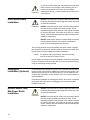
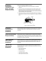
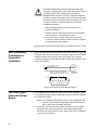
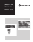
®
®
Spectra and
®
Digital Spectra
FM Two-Way Mobile Radios
Installation Manual
Foreword
The information contained in this manual relates to all Spectra® and ASTRO® Digital Spectra® mobile radios
unless otherwise specified. This manual provides information for installation of a Spectra or ASTRO Digital
Spectra mobile radio.
Safety Information
Before operating a Spectra or ASTRO Digital Spectra mobile radio, please read the Motorola “Product Safety
and RF Energy Exposure Booklet for Mobile Two-Way Radios Installed in Vehicles or as Fixed Site Control
Stations.”
Manual Revisions
Changes which occur after this manual is printed are described in “FMRs.” These FMRs provide complete
information on changes including pertinent parts listing data.
Computer Software Copyrights
The Motorola products described in this manual may include copyrighted Motorola computer programs stored
in semiconductor memories or other media. Laws in the United States and other countries preserve for Motorola
certain exclusive rights for copyrighted computer programs, including, but not limited to, the exclusive right to
copy or reproduce in any form the copyrighted computer program. Accordingly, any copyrighted Motorola
computer programs contained in the Motorola products described in this manual may not be copied,
reproduced, modified, reverse-engineered, or distributed in any manner without the express written permission
of Motorola. Furthermore, the purchase of Motorola products shall not be deemed to grant either directly or by
implication, estoppel, or otherwise, any license under the copyrights, patents or patent applications of Motorola,
except for the normal non-exclusive license to use that arises by operation of law in the sale of a product.
Installation Requirements for Compliance with
Radio Frequency (RF) Energy Exposure Safety
Standards
ATTENTION!
This radio is intended for use in occupational/controlled conditions, where users have full knowledge of their
exposure and can exercise control over their exposure to meet FCC limits. This radio device is NOT authorized
for general population, consumer, or any other use.
To ensure compliance to RF Energy Safety Standards:
•
Install only Motorola approved antennas and accessories.
•
Be sure that antenna installation is per Antenna Installation on page 3-8 of this manual.
•
Be sure that Product Safety and RF Safety Booklet enclosed with this radio is available to the end user
upon completion of the installation of this radio.
Before using this product, the operator must be familiar with the RF energy awareness information and
operating instructions in the Product Safety and RF Exposure booklet enclosed with each radio (Motorola
publication part number 6881095C99_) to ensure compliance with Radio Frequency (RF) energy exposure
limits.
!
For radios installed in vehicles fuelled by liquefied petroleum gas, refer to the (U.S.)
National Fire Protection Association standard, NFPA58, for storage, handling, and/or
container information.
WARNING
This radio has a transmitter Time-out Timer that disables the transmitter during a transmission after a predefined
time period, which by default is set to 60 seconds.
!
It is recommended NOT to change the default 60 seconds time period for the Time-out Timer
as the radio is intended for intermittent duty cycle operation.
Caution
For a list of Motorola-approved antennas and other accessories, visit the following web site, which lists approved
accessories for your radio model:
http://www.motorola.com/governmentandenterprise
Notes
Table of Contents
1 - Description . . . . . . . . . . . . . . . . . . . . . . . . . . . . . . . . . . . . . . . . . . . . . . . . . . . . . . . . . . . . . . . . . . . . . .
Introduction. . . . . . . . . . . . . . . . . . . . . . . . . . . . . . . . . . . . . . . . . . . . . . . . . . . . . . . . . . . . . . . . . . . . . . .
Radio Model, Control Head, and Version Identification . . . . . . . . . . . . . . . . . . . . . . . . . . . . . . . . . . . . .
Radio Dimensions . . . . . . . . . . . . . . . . . . . . . . . . . . . . . . . . . . . . . . . . . . . . . . . . . . . . . . . . . . . . . . . . .
Base/Control Stations. . . . . . . . . . . . . . . . . . . . . . . . . . . . . . . . . . . . . . . . . . . . . . . . . . . . . . . . . . . . . . .
1
1
1
2
2
2 - Installation . . . . . . . . . . . . . . . . . . . . . . . . . . . . . . . . . . . . . . . . . . . . . . . . . . . . . . . . . . . . . . . . . . . . . . 4
Planning the Installation . . . . . . . . . . . . . . . . . . . . . . . . . . . . . . . . . . . . . . . . . . . . . . . . . . . . . . . . . . . . . 4
Speaker Installation . . . . . . . . . . . . . . . . . . . . . . . . . . . . . . . . . . . . . . . . . . . . . . . . . . . . . . . . . . . . . . . . 4
Microphone Hang-up Clip Installation . . . . . . . . . . . . . . . . . . . . . . . . . . . . . . . . . . . . . . . . . . . . . . . . . . 8
Handheld Hang-up Box Installation (A3 Model Control Head) . . . . . . . . . . . . . . . . . . . . . . . . . . . . . . . . 8
Low-/Mid-Power Radio Power Cable Installation . . . . . . . . . . . . . . . . . . . . . . . . . . . . . . . . . . . . . . . . . . 8
High-Power Radio Power Cable Installation . . . . . . . . . . . . . . . . . . . . . . . . . . . . . . . . . . . . . . . . . . . . . 8
Remote Radio Control Cable Installation . . . . . . . . . . . . . . . . . . . . . . . . . . . . . . . . . . . . . . . . . . . . . . . . 9
Dash Mount Radio Installation . . . . . . . . . . . . . . . . . . . . . . . . . . . . . . . . . . . . . . . . . . . . . . . . . . . . . . . 10
Locking Kit Installation (Optional). . . . . . . . . . . . . . . . . . . . . . . . . . . . . . . . . . . . . . . . . . . . . . . . . . . . . 10
Remote Mount Low-/Mid-Power Radio Installation . . . . . . . . . . . . . . . . . . . . . . . . . . . . . . . . . . . . . . . 10
Remote Mount High-Power Radio Installation . . . . . . . . . . . . . . . . . . . . . . . . . . . . . . . . . . . . . . . . . . . 11
Remote A4, A5, A7, and A9 Model Control Head Installation . . . . . . . . . . . . . . . . . . . . . . . . . . . . . . . 12
Remote A3 Model Control Head Installation . . . . . . . . . . . . . . . . . . . . . . . . . . . . . . . . . . . . . . . . . . . . 13
Transmit/Receive Control Cable Installation (A4, A5, A7, and A9 Remote Control Heads). . . . . . . . . 14
Transmitter Control Power Lead (Orange) . . . . . . . . . . . . . . . . . . . . . . . . . . . . . . . . . . . . . . . . . . . 16
Receiver Control Power Lead (Green) . . . . . . . . . . . . . . . . . . . . . . . . . . . . . . . . . . . . . . . . . . . . . . 17
Ignition Cable (for Remote A3 Control Heads and Dash Mount Radios) . . . . . . . . . . . . . . . . . . . . . . . 17
Alternator Whine Suppressor Installation . . . . . . . . . . . . . . . . . . . . . . . . . . . . . . . . . . . . . . . . . . . . . . . 17
Antenna Installation . . . . . . . . . . . . . . . . . . . . . . . . . . . . . . . . . . . . . . . . . . . . . . . . . . . . . . . . . . . . . . . 17
Selecting an Antenna Site/Location on a Metal Body Vehicle . . . . . . . . . . . . . . . . . . . . . . . . . . . . 17
Antenna Installation Procedure . . . . . . . . . . . . . . . . . . . . . . . . . . . . . . . . . . . . . . . . . . . . . . . . . . . . 18
Antenna Connection . . . . . . . . . . . . . . . . . . . . . . . . . . . . . . . . . . . . . . . . . . . . . . . . . . . . . . . . . . . . 19
Phone Button Key Installation . . . . . . . . . . . . . . . . . . . . . . . . . . . . . . . . . . . . . . . . . . . . . . . . . . . . . . . 19
Options and Accessories Installation for A4, A5, A7, and A9 Model Control Heads . . . . . . . . . . . . . . 20
VIP Output Connections . . . . . . . . . . . . . . . . . . . . . . . . . . . . . . . . . . . . . . . . . . . . . . . . . . . . . . . . . 20
VIP Input Connections . . . . . . . . . . . . . . . . . . . . . . . . . . . . . . . . . . . . . . . . . . . . . . . . . . . . . . . . . . 20
Emergency Pushbutton, Footswitch, Horn Relay, and Light Relay Installation . . . . . . . . . . . . . . . . . . 21
Emergency Pushbutton or Footswitch Installation . . . . . . . . . . . . . . . . . . . . . . . . . . . . . . . . . . . . . . . . 21
Horn (External Alarm) Relay Installation . . . . . . . . . . . . . . . . . . . . . . . . . . . . . . . . . . . . . . . . . . . . . . . 21
Lights (External Alarm) Relay Installation . . . . . . . . . . . . . . . . . . . . . . . . . . . . . . . . . . . . . . . . . . . . . . 21
Options and Accessories Installation . . . . . . . . . . . . . . . . . . . . . . . . . . . . . . . . . . . . . . . . . . . . . . . . . . 21
MDC Emergency Pushbutton or Footswitch Installation . . . . . . . . . . . . . . . . . . . . . . . . . . . . . . . . . . . 22
Horn and Lights (External Alarms) Relays . . . . . . . . . . . . . . . . . . . . . . . . . . . . . . . . . . . . . . . . . . . . . . 22
Connecting Cables . . . . . . . . . . . . . . . . . . . . . . . . . . . . . . . . . . . . . . . . . . . . . . . . . . . . . . . . . . . . . . . . 24
Replacement Parts Ordering . . . . . . . . . . . . . . . . . . . . . . . . . . . . . . . . . . . . . . . . . . . . . inside rear cover
A, Motorola, ASTRO, and Spectra are trademarks of Motorola Inc.
© 1993, 2001, 2008 by Motorola Inc.
Commercial, Government and Industrial Solutions Sector
8000 W. Sunrise Blvd., Ft. Lauderdale, FL 33322
Printed in U.S.A. 8/08. All Rights Reserved.
68P81070C85-D
Installation Manual
i
List of Figures
Figure 1
Figure 2
Figure 3
Figure 4
Figure 5
Figure 6
Figure 7
Figure 8
Figure 9
Figure 10
Figure 11
Figure 12
Figure 13
Figure 14
Figure 15
Figure 16
Figure 17
Figure 18
Figure 19
Figure 20
Example of a Base/Control Station Configuration . . . . . . . . . . . . . . . . . . . . . . . . . . . . . . . . . . . . . . . . .3
High-Power Radio Installation (Remote) Using A4, A5, A7 or A9 Control Heads . . . . . . . . . . . . . . .5
High-Power Radio Installation (Remote) Using A3 Control Heads . . . . . . . . . . . . . . . . . . . . . . . . . . .5
Low-/Mid-Power Radio Installation (Dash Mount) Using A4, A5, or A7 Control Heads. . . . . . . . . . .6
Low-/Mid-Power Radio Installation (Remote) Using A4, A5, A7 or A9 Control Heads . . . . . . . . . . .6
Low-/Mid-Power Radio Installation (Dash Mount) Using A3 Control Heads. . . . . . . . . . . . . . . . . . . .7
Low-/Mid-Power Radio Installation (Remote) Using A3 Control Heads . . . . . . . . . . . . . . . . . . . . . . .7
Cabling Interconnect Diagram. . . . . . . . . . . . . . . . . . . . . . . . . . . . . . . . . . . . . . . . . . . . . . . . . . . . . . . . .8
High-Power Main Fuse Assembly (40-Amp) . . . . . . . . . . . . . . . . . . . . . . . . . . . . . . . . . . . . . . . . . . . . .9
A4, A5, and A7 Control Head Installation Exploded View . . . . . . . . . . . . . . . . . . . . . . . . . . . . . . . . .13
A4, A5, and A7 Control Head Rear View . . . . . . . . . . . . . . . . . . . . . . . . . . . . . . . . . . . . . . . . . . . . . . .13
A9 Control Head Installation Exploded View . . . . . . . . . . . . . . . . . . . . . . . . . . . . . . . . . . . . . . . . . . . .14
Alternator Whine Suppressor Isolation Detail. . . . . . . . . . . . . . . . . . . . . . . . . . . . . . . . . . . . . . . . . . . .15
Fuseholder Assembly and Parts List for Orange and Green Control Cables. . . . . . . . . . . . . . . . . .16
Antenna connections on the back of the radio. . . . . . . . . . . . . . . . . . . . . . . . . . . . . . . . . . . . . . . . . . .18
Mini-UHF Connection. . . . . . . . . . . . . . . . . . . . . . . . . . . . . . . . . . . . . . . . . . . . . . . . . . . . . . . . . . . . . . .19
Installing the Phone Button Key on A4, A5, and A7 Model Control Heads. . . . . . . . . . . . . . . . . . . .20
VIP Connector Detail . . . . . . . . . . . . . . . . . . . . . . . . . . . . . . . . . . . . . . . . . . . . . . . . . . . . . . . . . . . . . . .21
Emergency Switch Wiring Diagram . . . . . . . . . . . . . . . . . . . . . . . . . . . . . . . . . . . . . . . . . . . . . . . . . . .22
Horn/Light Wiring Diagram. . . . . . . . . . . . . . . . . . . . . . . . . . . . . . . . . . . . . . . . . . . . . . . . . . . . . . . . . . .23
List of Tables
Table 1
Radio Functions Connections . . . . . . . . . . . . . . . . . . . . . . . . . . . . . . . . . . . . . . . . . . . . ..15
Related Publications
Spectra Detailed Service Manual . . . . . . . . . . . . . . . . . . . . . . . . . . . . . . . . . . . . . . . . . . 68P80102W61
ASTRO Spectra Motorcycle Radios Supplemental Installation Manual . . . . . . . . . . . . . . 68P80103W01
ASTRO Digital Spectra Hand-Held Control Head (Model W3) User’s Guide . . . . . . . . . .68P81073C25
Spectra VHF VCO Section Detailed Service Manual Supplement . . . . . . . . . . . . . . . . . .68P81074C48
ASTRO Digital Spectra (Models W4, W5, W7, and W9) User’s Guide . . . . . . . . . . . . . . .68P81074C80
ASTRO Digital Spectra Mobile Radios Basic Service Manual . . . . . . . . . . . . . . . . . . . . . .68P81076C20
ASTRO Digital Spectra Mobile Radios Detailed Service Manual . . . . . . . . . . . . . . . . . . . .68P81076C25
Spectra High-Power Power Amplifier Detailed Service Manual Supplement . . . . . . . . . .68P81077C25
Spectra Systems 9000 Control Unit Detailed Service Manual Supplement . . . . . . . . . . .68P81077C30
Spectra “E” Mobile Radios Detailed Service Manual . . . . . . . . . . . . . . . . . . . . . . . . . . . . .68P81077C40
Spectra A5 and A7 Control Head Instruction Manual. . . . . . . . . . . . . . . . . . . . . . . . . . . . .68P81109C33
Spectra A4 Control Head Detailed Instruction Manual . . . . . . . . . . . . . . . . . . . . . . . . . . . .68P81109C34
ii
1
Description
Introduction
This manual covers the installation procedures for Spectra® and ASTRO®
Digital Spectra radios and accessories required to complete the radio
system. The radio system consists of a control head, radio, antenna,
microphone, speaker, cabling, and accessories.
Radio Model, Control
Head, and Version
Identification
Model charts for the different versions are found in the basic service
manual. “Versions” are identified by the model number “suffix.” Although
the charts are very similar, there are subtle but very important differences.
Determine from the radio's identification label, which model control head
and version is yours. Keep this information handy for future references.
Determine the model and version of the radio as follows:
Power of the Radio
SPECTRA
Typical model number – D 4 3 K M A 7 K A 7 A K
Type of Mount
Version
Control Head Model
If your model number begins with a “D,” your radio is dash mounted; if it
begins with a “T,” it is a remote unit. In the above example the “4” refers to
the radio power; “8” is high,“4” is mid, and “3” is low power. The “A7” refers
to the control head model number, and the letter “A” refers to the version.
ASTRO SPECTRA
Power of the Radio
Typical model number – T 0 4 S L F 9 K W 7 A N
Type of Mount
Control Head Model
Version
If your model number begins with a “D,” your radio is dash mounted; if it
begins with a “T,” it is trunk mounted. In the above example the “L” refers
to the radio power (“A” is low power, “L” is high), and varies between “A”
to “L”). The “A7” refers to the control head model number, and the letter
“A” refers to the version.
1
Radio Dimensions
The Spectra and ASTRO Spectra Radios have the following dimensions
(H x W x D):
15-watt – 2.0” x 7.1” x 7.5”
20- to 35-watt and 40-watt – 2.0” x 7.1” x 8.6”
Base/Control
Stations
Model charts for the different versions are found in the basic service
manual. “Versions” are identified by the model number “suffix.” Although
the charts are very similar, there are subtle but very important differences.
Determine from the radio's identification label, which model control head
and version is yours. Keep this information handy for future references.
Determine the model and version of the radio as follows:
!
Caution
For outdoor antenna installations, proper site grounding and
lightning protection are vitally important. Failure to provide
proper lightning protection may result in permanent damage
to the radio equipment. Refer to Motorola Quality Standards
Fixed Network Equipment Installation Manual R56
(6881089E50), for complete information regarding lightning
protection.
•
The antenna should be mounted outside the building on the roof or a
tower if at all possible and the antenna cable should be earth
grounded.
•
The radio chassis must be earth grounded and a lightning surge
protector should be used in line with the radio connector and the
outdoor antenna. The lightning surge protector should be earth
grounded and located at the point where the antenna cable enters the
building.
•
The line voltage power supply must have a proper ground connection.
•
As with all fixed site antenna installations, it is the responsibility of the
licensee to manage the site in accordance with applicable regulatory
requirements. Also, additional compliance actions such as site survey
measurements, signage, and site access restrictions may be required
in order to ensure that exposure limits are not exceeded.
Figure 1 shows a typical setup of a Base/Control Station configuration.
2
Walloutlet
Line Cord
with Ground
Power Supply
Outdoor Antenna
Desktop
Power Cable
Lightning Protector With
Quarter Wave Shorting Stub
Speaker
C
C C CCC
C CC C
C
CC
CC
CC
CC
CCCC
Antenna
Cable
Antenna Connector
CC
CC
C
C
Desk
Microphone
CC C
CC
CC
Radio in
Desktop Tray
Figure 1 Example of a Base/Control Station Configuration
3
2
Installation
NOTE:
Planning the
Installation
In this manual, all information relating to a specific
control-head model (A3, A4, A5, A7, or A9) will be
applicable to a similar control head in the ASTRO Digital
Spectra and Spectra radio families. Examples, A4
control head installation is also applicable to control
heads B4, E4, and W4 control heads; A7 control head
installation is also applicable to control heads B7, E7,
and W7.
Figures 2 through 7 show all the possible configurations. The title under
each figure identifies which power radio and which model control head is
being shown and whether the radio can be remote or dash mounted
(only low-/mid-power radios can be dash mounted). Identify which of the
first six figures shows the configuration being installed and use the
diagram when planning the installation.
The Spectra radio should operate only in negative ground electrical
systems. Check the ground polarity of the vehicle before starting the radio
installation making sure the polarity is correct. Accidentally reversing the
polarity will not damage the radio, but will cause the cable fuses to blow.
Speaker Installation
!
Caution
DO NOT ground the radio's speaker leads. This system
has a floating speaker output (dc voltage on both leads);
damage to the audio circuit will result if either lead is
grounded or if they are shorted together.
The speaker kit includes a trunnion bracket that allows the speaker to be
mounted in a variety of ways. With the trunnion bracket, the speaker can
mount permanently on the dashboard or in accessible firewall areas. The
trunnion allows the speaker to tilt for best operation. Mount the speaker out
of the way so that it will not be kicked or knocked around by the vehicle
occupants. Mount the speaker as follows:
1. Use the speaker mounting bracket as a template to mark the mounting
hole locations.
2. Use the self-drilling screws provided to fasten the trunnion.
3. Attach the speaker and fasten to the trunnion with two wing screws.
4. Route the speaker wires under the carpet or floor covering, or behind
the kick panels. Be sure the wires are out of the way and will not be
snagged and broken by the occupants of the vehicle.
4
FUSE
BATTERY
(+)
RED LEAD
PORT ON BACK OF CONTROL HEAD
GRN LEAD FUSE
(-)
FIREWALL
HOLE
FUSE
BLOCK
VIP
1
2
MIC
3 4
7
5
18 19 20 21
ORG LEAD
REMOTE
MOUNT CONTROL
CABLE
FUSE
HORN
RELAY
RADIO
10 11 12 13 14 15 16 17
8
23 24
34 35 36 37 38
26 27 28 29 30 31 32 33
43 44 45 46 47 48 49 50
40 41
VIP SECTION PIN OUT
LIGHT
RELAY
PWR
Mode
MIC
CLIP
Phon
Scan
Call
Sel
Vol
SPEAKER
2
3
4 Sts
5
6 Msg
7H/L
8 Mon
9 Dir
BUSY
Rcl
HOME
0
18 SWB +
34 VIP OUT - 3 / DEK STROBE
2 VIP OUT - 1
19 SWB +
35 SWB +
3 VIP IN - 2
20 GROUND
36 GROUND
4 VIP IN - 1
21 GROUND
37 VIP IN - 3 / DEK DATA IN
5 DEK DATA OUT
XMIT
DIM
MIC
1
1 VIP OUT - 2
38 DEK CLOCK
Del
CONTROL HEAD*
MIC
EMERGENCY
SWITCH
RADIO
POWER
CABLE
ANTENNA
ANTENNA
CONNECTION
DESCRI
EH
ILLUSTR
JC
MAEPF-21355-O
EDITO
* MODEL A7 SHOWN
Figure 2 High-Power Radio Installation (Remote) Using A4, A5, A7 or A9 Control Heads
FUSE
BATTERY
(+)
J3
REMOTE MOUNT
ACCESSORY CONNECTOR
RED LEAD
(-)
FIREWALL
HOLE
FUSE
BLOCK
SPKR
NOTE 1
IGNITION
HUB
LO
SPKR
SWB+
EMER
HI
DIG
GND
IGNITION CABLE
LIGHT OR
HORN
RELAY
7
8
FUSE
15
SEE
PIN-OUT
HANG-UP
BOX
REMOTE
MOUNT CONTROL
CABLE
5
6
14
13
NC
NC
BUS+
4
12
3
2
11
10
NOTE 2
VIP OUT 1
1
9
BUSY
BUS-
NOTES:
1. TX AUDIO IN SP CUSTOMER APPLICATIONS.
2. DET AUDIO IN SP CUSTOMER APPLICATIONS.
SPEAKER
HANDHELD
CONTROL
HEAD
EMERGENCY
SWITCH
RADIO
POWER
CABLE
ANTENNA
ANTENNA
CONNECTION
MAEPF-21454-O
Figure 3 High-Power Radio Installation (Remote) Using A3 Control Heads
5
J2
REAR ACCESSORY CONNECTOR
(ASTRO SPECTRA)
FUSE
BATTERY
(+)
RED LEAD
SPKR
NOTE 1 VIP OUT 2 VRS TX/
LO
IGNITION NOTE 1 CTS-RS232
SPKR
SWB+
EMER
HI
ANTENNA
(-)
DIG
GND
FUSE
BLOCK
FIREWALL
HOLE
8
IGNITION CABLE
HORN
RELAY
ANTENNA
CONNECTION
PIN-OUT
LIGHT
RELAY
PWR
Mode
Phon
Scan
MIC
2
3
4 Sts
5
6 Msg
7H/L
8 Mon
9 Dir
XMIT
BUSY
DIM
SPEAKER
1
Sel
Call
Vol
Rcl
HOME
0
Del
6
14
5
13
BUS+
4
3
11
12
VIP OUT 1
NOTE1
2
1
9
10
BUSBUSY
MIC HI/RESET/
RTS-RS232
TRUNNION
MIC
CLIP
7
15
DC POWER
SEE CABLE
FUSE
PTT/ DISC. AUD/
TX-RS232 RX-RS232
J2
REAR ACCESSORY CONNECTOR
(SPECTRA)
MOUNTING
SCREWS
CONTROL HEAD*
SPKR
NOTE 4 VIP OUT 2
LO
IGNITION NOTE 4 NOTE 2
SPKR
HI
SWB+
EMER
MIC
DIG
GND
TRUNNION ORIENATION
7
8
15
MIC
HI
RADIO
FRONT
EMERGENCY
SWITCH
13
4
12
NOTE 1
BUS+
3
2
11
10
BUSY
NOTE 3
VIP OUT 1
NOTE 4
1
9
BUS-
NOTES:
1. PTT IN SP CUSTOMER APPLICATIONS.
2. TX AUDIO IN SP CUSTOMER APPLICATIONS.
3. DET AUDIO IN SP CUSTOMER APPLICATIONS.
4. FUNCTIONAL ONLY IN DASH MOUNT
CONFIGURATION, N.C. IN REMOTE MOUNT
CONFIGURATION.
APPLIES TO RADIOS WITH INTEGRAL
OR REMOTE MOUNT CONTROL UNITS
* MODEL A7 SHOWN
5
6
14
MAEPF-21356-A
Figure 4 Low-/Mid-Power Radio Installation (Dash Mount) Using A4, A5, or A7 Control Heads
FUSE
BATTERY
(+)
GRN LEAD FUSE
PORT ON BACK OF CONTROL HEAD
(-)
VIP
FUSE
BLOCK
1
REMOTE
MOUNT
CONTROL
ANTENNA
CABLE
ORG LEAD
FUSE
HORN
RELAY
2
3 4
MIC
7
5
18 19 20 21
23 24
34 35 36 37 38
RADIO
10 11 12 13 14 15 16 17
8
26 27 28 29 30 31 32 33
40 41
43 44 45 46 47 48 49 50
VIP SECTION PIN OUT
LIGHT
RELAY
PWR
MIC
CLIP
Mode
Phon
Vol
SPEAKER
Call
Sel
1
2
3
4 Sts
5
6 Msg
7H/L
8 Mon
9 Dir
XMIT
DIM
MIC
Scan
BUSY
Rcl
HOME
CONTROL HEAD*
MIC
0
Del
1 VIP OUT - 2
18 SWB +
34 VIP OUT - 3 / DEK STROBE
2 VIP OUT - 1
19 SWB +
35 SWB +
3 VIP IN - 2
20 GROUND
36 GROUND
4 VIP IN - 1
21 GROUND
37 VIP IN - 3 / DEK DATA IN
5 DEK DATA OUT
FIREWALL
HOLE
DC POWER
CABLE
38 DEK CLOCK
OPTIONAL LOCKING KIT
ANTENNA
CONNECTION
BOTTOM LOCK
HOUSING
RADIO
TOP LOCK
HOUSING
EXISTING
MOUNTING SCREWS
EMERGENCY
SWITCH
* MODEL A7 SHOWN
LOCK
APPLIES TO RADIOS WITH INTEGRAL
OR REMOTE MOUNT CONTROL UNITS
MAEPF-21357-O
Figure 5 Low-/Mid-Power Radio Installation (Remote) Using A4, A5, A7 or A9 Control Heads
6
BATTERY
(+)
J2
REAR ACCESSORY CONNECTOR
(ASTRO SPECTRA)
FUSE
ANTENNA
SPKR
NOTE 1 VIP OUT 2 VRS TX/
LO
IGNITION NOTE 1 CTS-RS232
SPKR
SWB+
EMER
HI
(-)
FUSE
BLOCK
DIG
GND
FIREWALL
HOLE
8
IGNITION CABLE
LIGHT OR
HORN
RELAY
FUSE
DC POWER
SEE CABLE
PIN-OUT
HANG-UP
BOX
7
15
ANTENNA
CONNECTION
6
14
5
13
BUS+
4
3
2
11
12
VIP OUT 1
NOTE1
BUSBUSY
MIC HI/RESET/
RTS-RS232
TRUNNION
1
9
10
PTT/ DISC. AUD/
TX-RS232 RX-RS232
MOUNTING
SCREWS
SPEAKER
J2
REAR ACCESSORY CONNECTOR
(SPECTRA)
CONTROL HEAD
HANDHELD
CONTROL
HEAD
SPKR
NOTE 2
IGNITION
HUB
LO
SPKR
HI
SWB+
EMER
DIG
GND
TRUNNION ORIENATION
7
8
15
RADIO
FRONT
MIC
HI
EMERGENCY
SWITCH
5
6
14
4
NOTE 1
BUS+
3
12
13
2
11
10
BUSY
NOTE 3
VIP OUT 1
1
9
BUS-
NOTES:
1. PTT IN SP CUSTOMER APPLICATIONS.
2. TX AUDIO IN SP CUSTOMER APPLICATIONS.
3. DET AUDIO IN SP CUSTOMER APPLICATIONS.
APPLIES TO OPERATOR COMPARTMENT
OR REMOTE MOUNT RADIOS
MAEPF-21358-A
Figure 6 Low-/Mid-Power Radio Installation (Dash Mount) Using A3 Control Heads
BATTERY
(+)
J3
REMOTE MOUNT
ACCESSORY CONNECTOR
FUSE
SPKR
NOTE 1
IGNITION
HUB
LO
SPKR
SWB+
EMER
HI
(-)
DIG
GND
FUSE
BLOCK
IGNITION CABLE
LIGHT OR
HORN
RELAY
7
8
FUSE
15
5
6
14
13
4
12
3
2
11
10
1
9
SEE
PIN-OUT
HANG-UP
BOX
REMOTE
MOUNT CONTROL
CABLE
NC
NC
BUS+
NOTE 2
VIP OUT 1
BUSY
BUS-
NOTES:
1. TX AUDIO IN SP CUSTOMER APPLICATIONS.
2. DET AUDIO IN SP CUSTOMER APPLICATIONS.
SPEAKER
FIREWALL
HOLE
DC POWER
CABLE
HANDHELD
CONTROL
HEAD
OPTIONAL LOCKING KIT
ANTENNA
CONNECTION
RADIO
EMERGENCY
SWITCH
BOTTOM LOCK
HOUSING
EXISTING
MOUNTING SCREWS
TOP LOCK
HOUSING
LOCK
APPLIES TO OPERATOR COMPARTMENTS
OR REMOTE MOUNT RADIOS
MAEPF-21359-O
Figure 7 Low-/Mid-Power Radio Installation (Remote) Using A3 Control Heads
7
Microphone
Hang-up Clip
Installation
The hang-up clip must be within reach of the operator(s). Measure this
distance before actually mounting the bracket. Since the bracket has a
positive-detent action, the microphone can mount in any position. The
microphone hang-up clip must be grounded.
Use the hang-up clip as a template to locate the mounting holes. To avoid
interference when removing the microphone, install the flathead screw in
the top clip hole.
Handheld Hang-up
Box Installation
(A3 Model Control
Head)
Use the hang-up box (HUB) as a template to locate the mounting holes.
Be sure the HUB will be within easy reach of the operator. Route the
control wire with the male pin to the accessory cable connector at the rear
of the radio or cable harness as shown in Figures 6 and 7. Open the
accessory cable connector and connect the HUB control wire to location 3
of the accessory connector. Connect the other control wire from the HUB
to a convenient solid chassis ground point.
Low-/Mid-Power
Radio Power Cable
Installation
Route the red radio power cable from the radio to the vehicle’s battery
compartment, using accepted industry methods and standards. Be sure to
grommet the firewall hole to protect the cable. Remove the 15-amp
(P/N 6580283E06) fuse from the fuseholder and connect the red lead of
the radio power cable to the positive battery terminal using the hardware
provided as shown in 8. Connect the black lead to a convenient solid
chassis ground point. DO NOT connect the black lead directly to the
battery’s negative terminal.
RADIO COMPARTMENT
CAUTION
A good chassis connection via
the black primary power cable
is essential for radio operation
and to prevent damage to the
radio and cable kit. Connection
to the vehicle frame is desirable.
OPERATOR COMPARTMENT
VEHICLE BATTERY
COMPARTMENT
MICROPHONE
VEHICLE
IGNITION SWITCH
VIP
TRANSMITTER
CONTROL
CABLE (ORG)
RADIO (ORG)
(GRN)
MIC
ON/ACC
PART OF
VEHICLE
WIRING
3.0A FUSE
SEE NOTE
SPEAKER
RADIO
(+)
RADIO
POWER CABLE
(BLK/GROUND)
RADIO CONTROL
CABLE (BLK/MULTICONDUCTOR)
RECEIVER
CONTROL
CABLE (GRN)
RADIO POWER CABLE
(RED/BATTERY HOT)
15A OR 40A
FUSE
(-)
VEHICLE
BATTERY
NOTE:
The orange and green power cables connect to either the vehicle battery or the ignition switch. Connect the green cable directly to the battery. The receiver operates
when the control head is on. Connect the orange cable to the ignition switch. The transmitter operates only when the ignition switch is on. Alternate connectionsConnecting both green and orange cables to the battery allows the control head to turn the receiver and transmitter on or off. Connecting both green and orange cables
to the ignition switch allows the ignition switch to turn the receiver and transmitter on or off. (Alternator whine and other noise problems may occur. Isolate the green
cable with a Motorola relay, part #59-00813674.)
Figure 8 Cabling Interconnect Diagram
High-Power Radio
Power Cable
Installation
8
As shown in Figure 8, route the bare end of the red radio power cable from
the radio to the vehicle’s battery compartment, using accepted industry
procedures and standards. Be sure to grommet the firewall hole to protect
the cable. After the long cable has been routed to the battery compartment,
decide on a location for the fuse retainer. When choosing this location,
consider ease of checking and replacing fuses. This location should also
be as close to the battery as possible for better protection of the radio and
cabling.
Remove the fuse from the fuseholder and connect the short red cable with
the fuse connection to the positive battery terminal. Cut the long red radio
power cable to the proper length and strip the red insulation back 3/4" from
the end. Slide the heat-shrink tubing provided with the equipment over the
cable. Insert the stripped end into the fuse receptacle (assembly shown in
Figure 9), and solder it for a good electrical connection. After soldering has
been completed, slide the heat-shrink tubing over the solder joint and
apply heat. DO NOT install the fuse until instructed to do so.
Connect the red cable from the fuseholder to the positive battery terminal.
Connect the black radio power lead, from the radio, to a good ground
connection on the vehicle chassis. DO NOT connect the black radio power
lead directly to the battery’s negative terminal.
TO POSITIVE
BATTERY TERMINAL
3
4
5
1
2
6
MAEPF-21363-O
J
ED
TO RADIO
Figure 9 High-Power Main Fuse Assembly (40-Amp)
Exploded View Parts List
Fuse Assembly for High-Power Main Fuse (40-Amp)
Remote Radio
Control Cable
Installation
REFERENCE
SYMBOL
MOTOROLAP
ART NO.
DESCRIPTION
1
0300139931
SCREW
2
0984277B02
RECEPTACLE, Fuse
3
3884383D02
CAP, Protective
4
4284275B01
FUSE, Retainer
5
6584161B01
FUSE, 40-Amp (5AG)
6
3700134371
TUBING, Heat-Shrink
The radio control cable should go from the rear of the control head to the
radio. Route the cables in the vehicle’s wiring troughs (where available) or
route the cables where they are protected from pinching, sharp edges, or
crushing. One suggested route is along one side of the driveshaft hump
under the carpet. Use grommets in any holes where the cable passes
through metal panels. Figure 8 shows how the cables and components are
connected.
9
!
Caution
Dash Mount Radio
Installation
!
Caution
To ensure a proper water seal, the jackscrews on the radio
cable connector must be tight. If the accessory port on a
remote mounted radio is not used, the cover gasket
assembly (HLN6233_) must be installed and torqued to 6 to
8 inch-pounds.
DO NOT mount the radio on a plastic dashboard without first
reinforcing the dashboard; the weight of the radio may crack
or break the dashboard.
DO NOT mount the radio on a flat or concave surface where
the radio could be partially submersed in water. This is
especially important if the cab area of the vehicle is cleaned
by spraying with water. If the radio sits in water for a length
of time, moisture will seep inside the radio and damage the
electronic components.
DO NOT allow water to stand in recessed areas of vertically
mounted radios. Remove any moisture immediately to
prevent it from seeping down into the radio.
The mounting location must be accessible and visible. Select a location
that will permit routing the RF antenna cable as directly as possible. See
Figures 4 and 6 for typical dash mount radio installations.
NOTE:
For optimum radio performance, orient the mounting
trunnion as shown in Figures 4 and 6.
Use the radio’s mounting trunnion as a template to mark the mounting hole
locations. Fasten the trunnion to the dash (or on the transmission hump)
using the self-drilling screws provided.
Locking Kit
Installation (Optional)
If a locking kit is used (shown in Figures 5 and 7) position the lock bottom
housing on the trunnion before installing the radio mounting screws. Then
slip the top lock housing on and remove the key. You can install the lock
on either side of the radio, and by rotating it 180°, you can also install it on
dash installations.
Complete the installation by mounting the radio in its trunnion, connecting
the speaker and power wires, and plugging in the microphone cable/
handheld control unit.
Remote Mount Low-/
Mid-Power Radio
Installation
!
Caution
10
DO NOT mount the radio on a plastic dashboard without first
reinforcing the dashboard; the weight of the radio may crack
or break the dashboard.
DO NOT mount the radio on a flat or concave surface where
the radio could be partially submersed in water. This is
especially important if the cab area of the vehicle is cleaned
by spraying with water. If the radio sits in water for a length
of time, moisture will seep inside the radio and damage the
electronic components.
!
DO NOT allow water to stand in recessed areas of vertically
mounted radios. Remove any moisture immediately to
prevent it from seeping down into the radio.
Caution
For radios equipped with optional remote mount control heads, see
Figure 5. For radios equipped with remote handheld control heads, see
Figure 7. Choose a mounting location for the radio, considering
accessibility, and control and antenna cable lengths.
NOTE:
For optimum performance, orient the mounting trunnion
as shown in Figures 5 and 7. Also, if an optional locking
kit is used, position the lock bottom housing on the
trunnion before installing the radio mounting screws.
Then slip the top lock housing on and remove the key.
You can install the lock on either side of the radio.
Use the radio’s mounting trunnion as a template to mark the mounting hole
locations. Use the self-drilling screws provided to fasten the trunnion.
Install the radio and fasten it to the trunnion with the wing screws provided.
Remote Mount HighPower Radio
Installation
!
Caution
DO NOT mount the radio on a plastic dashboard without first
reinforcing the dashboard; the weight of the radio may crack
or break the dashboard.
DO NOT mount the radio on a flat or concave surface where
the radio could be partially submersed in water. This is
especially important if the cab area of the vehicle is cleaned
by spraying with water. If the radio sits in water for a length
of time, moisture will seep inside the radio and damage the
electronic components.
DO NOT allow water to stand in recessed areas of vertically
mounted radios. Remove any moisture immediately to
prevent it from seeping down into the radio.
Choose a mounting location for the radio, considering accessibility, and
control and antenna cable lengths. With the radio appropriately located,
use the radio mounting tray as a template to mark the mounting hole
locations.
NOTE:
For optimum performance, orient the mounting tray and
radio as shown in Figures 2 and 3.
Use the self-drilling screws provided to fasten the mounting tray. Install the
radio and fasten it to the tray by aligning the radio to the tray with the
handle to the front (see Figures 2 and 3). Insert the key into the lock and
turn it clockwise to release the handle. Apply a downward force at the front
sides of the radio while sliding the radio back into the tray.
When the radio is in place, it can be locked into position by lifting the
handle into the upright position. The lock should “click” when the handle is
caught by the lock. Ensure proper locking engagement by attempting to lift
the radio out of position.
11
Remote A4, A5, A7,
and A9 Model Control
Head Installation
The recommended mounting surfaces for the control unit are under the
dashboard, on the transmission hump, or on the center console. Figure 10
shows an example of the A4, A5, and A7 control heads. Figure 12 shows
how the bracket, control head, and cables should be installed for the A9
model control head.
NOTE:
For Control Head Models A4, A5, and A7 only: To seal
the control head and meet U. S. MIL-STD-810D
environmental specifications, covers are supplied for
protection of the control head’s rear connector pins.
These covers are in the bag that is fastened to the
remote control head’s mounting trunnion.
If the VIP connector is not being used to connect options,
the VIP protective cover should be installed as shown in
Figure 11. If the microphone is connected to the front of
the control head, the MIC protective cover should be
installed as shown in Figure 11. Alternately, the
microphone can be connected to the rear connector in
place of the cover, and the control head will still be
environmentally sealed.
An adjustable trunnion, which allows a number of mounting positions, is
supplied for mounting the control unit. The installation must not interfere
with the operation of the vehicle or its accessories, nor disturb passenger
seating or leg room. The control head must be within convenient reach and
viewing of the user(s).
Although the trunnion can be mounted on a plastic dashboard, all four
mounting screws should penetrate the dashboard’s supporting metal
frame. If that is not possible, use a metal backing plate (not supplied) to
strengthen the installation. Install the control unit as follows:
1. Use the control unit trunnion as a template to mark the mounting
holes; drill 5/32" holes. If mounting on a plastic surface, use a metal
backing plate.
2. Attach the trunnion bracket using all four 10–16" x 5/8" self-tapping
screws provided.
NOTE:
When the control unit is installed, it must not wobble or
feel “spongy” when you press the buttons. Use all four
mounting screws and be sure they are tightly screwed
into metal – either a dashboard support bracket or a
backing plate.
3. Temporarily install the control head (adjusting for proper viewing
angle) and fasten it to the trunnion with two wing screws. Test the
installation to be sure the unit does not wobble or feel “spongy” when
you press the buttons.
!
Caution
12
Care must be taken to shield the control head (front and back)
from a direct exposure of pressurized water. The pressurized
water from a hose, in most cases, is more severe than the
stated test and conditions in typical environments.
IMPORTANT
USE A METAL BACKING PLATE
(NOT SUPPLIED) IF MOUNTING
TRUNNION ON A PLASTIC DASHBOARD
DRILL FOUR 5/32"
HOLES IN DASHBOARD
DASHBOARD
TRUNNION
03-00136756
USE FOUR MOUNTING SCREWS
ON ALL INSTALLATIONS
ADJUST THE CONTROL HEAD
TO DESIRED ANGLE AND
SECURE WITH WING SCREWS
VIP CONNECTOR
TO
RADIO
ORANGE AND
GREEN LEADS
TO
MICROPHONE
TO
SPEAKER
MAEPF-21453-O
Figure 10 A4, A5, and A7 Control Head Installation Exploded View
VIP CONNECTOR
PROTECTIVE COVER
MIC CONNECTOR
PROTECTIVE COVER
CONTROL CABLE
CONNECTOR
D
IL
Figure 11 A4, A5, and A7 Control Head Rear View
Remote A3 Model
Control Head
Installation
For the remote handheld control unit, mount the control cable with the
screws provided. Connect the control cable as shown in Figure 7. Connect
the speaker to the accessory cable harness.
13
IMPORTANT
USE A METAL BACKING PLATE
(NOT SUPPLIED) IF MOUNTING
TRUNNION ON A PLASTIC DASHBOARD
DRILL FOUR 5/32"
HOLES IN DASHBOARD
DASHBOARD
TRUNNION
03-00136756
USE FOUR MOUNTING SCREWS
ON ALL INSTALLATIONS
ADJUST THE CONTROL HEAD
TO DESIRED ANGLE AND
SECURE WITH WING SCREWS
VIP CONNECTOR
TO
RADIO
ORANGE AND
GREEN LEADS
TO
SPEAKER
MAEPF-21373-0
TO
MICROPHONE
TECHNICAL PUBLICATIONS DEPT.
DESCRIPTION
A9 Control Head Installation
DWG. NO.
MAEPF-21373
Figure 12 A9 Control Head Installation Exploded View
Transmit/Receive
Control Cable
Installation (A4, A5,
A7, and A9 Remote
Control Heads)
The radio system includes two separate wires, one orange (66") and one
green (106"). The HLH4952A Fuse Kit contains crimp-on ring tongue lugs
and crimp-on spade lugs. The spade lugs allow connection to hot leads at
the fuse block of the vehicle, and the ring tongue lugs permit attachment
to screw terminals. Determine from Table 1 which radio functions are to be
switched through the vehicle ignition switch.
A typical system allows the receiver to operate with the radio switched on
while the ignition switch is in the off position, but the transmitter will not
operate unless the ignition switch is in the on position. In this case, connect
the orange wire to the accessory terminal of the ignition switch and the
green wire to the ungrounded terminal of the battery or starter solenoid.
!
Caution
14
DO NOT connect either lead to the ungrounded terminal of
the battery at this time.
Table 1 Radio Functions Connections
Conductor
Connected to battery
Green
Orange
Green
X
X
X
Connected to ignition
switch
Ignition switch controls
No ignition switch control
Orange
Green
Orange
X
See Note
X
Transmitter ignition switch
controlled
Complete radio ignition
switch controlled
In any application, trim and strip wires. Crimp on ring lug for battery connections. For ignition switch connections, crimp
on ring or spade lug (whichever is required).
Note: In cases where alternator whine or interference is a problem, isolate the green lead with a relay (Motorola Part No.
5900813674) (see Figure 13).
RECEIVER
CONTROL CABLE
(GRN)
RELAY
MOTOROLA PART NO.
59-00813674
VEHICLE BATTERY
+
HOT
CHASSIS
-
PART OF
VEHICLE WIRING
ON/ACC
IGNITION SWITCH
MAEPF-21362-O
Figure 13 Alternator Whine Suppressor Isolation Detail
If either wire is to be connected in the vehicle’s battery compartment, pass
the end of the wire through the same firewall hole that the red radio power
cable uses. At this point, install a fuseholder assembly in both wires
(shown in Figure 14); the following procedures apply to both green and
orange wires:
•
A fuse will need to be placed in-line for both the orange and green
wires; consideration should be taken when deciding where to place
the fuses so that they are easy to inspect. However, they should also
be placed as close as possible to the battery or the vehicle’s ignition
switch terminal.
•
After choosing the fuse locations, the fuse receptacles need to be
installed. This is done by cutting the wire at the chosen location and
stripping 1/8-inch of insulation on all loose ends. Make sure the wire
will reach its intended destination.
•
On the end still connected to the cable kit, slide the plastic insulator
fuseholder over the wire as shown in Figure 9. Insert the stripped end
of that wire into one of the metal fuse clips, and crimp it closed onto
the exposed wire. Solder it for a better electrical contact.
•
On the end of the loose wire, repeat the above crimping and soldering
process with the remaining metal fuse clip.
15
•
Temporarily, install the fuse (both are 3-amp), into the fuse clips onto
both sides of the fuse. Slide the spring over the remaining loose end of
the wire. The spring should be followed by the plastic insulator
fuseholder oriented as shown in Figure 10. Slide the plastic insulator
fuse holder together, by first making sure the spring slips inside the
plastic insulator fuseholder cap. Now, twist the fuseholders until they
lock together. After assembly proves successful, remove the fuses
until instructed to install them later.
With the spring and plastic insulator fuseholder cap still in place on the
loose portion of the wires (orange and green), insert the stripped end of the
wire into the spade or ring tongue lug. Crimp and solder the lug as was
done on the metal fuse clips above.
SPADE OR RING
TONGUE LUG
(RING TONGUE
LUG SHOWN)
PLASTIC INSULATOR
FUSE HOLDER CAP
METAL FUSE
CLIPS CRIMP
AND SOLDER
TO WIRE
SPRING
FUSE
TO CONTROL
HEAD
PLASTIC INSULATOR
FUSE HOLDER
MAEPF-21361-O
Figure 14 Fuseholder Assembly and Parts List
for Orange and Green Control Cables
Parts List
Fuse Assembly for Orange and Green Leads
MOTOROLA
PART NO.
Transmitter Control
Power Lead (Orange)
16
DESCRIPTION
1482882A01
INSULATOR, Fuseholder Body
1482883A01
INSULATOR, Fuseholder Cap
2900136968
LUG
2900824456
LUG, Ring Tongue
2900865065
LUG, Ring Tongue
4182885A01
SPRING, Compression; Fuse
4282884Q01
CLIP, Fuse
6500020404
FUSE, 3-Amp 250V (Qty. 2)
Connect the orange lead to the ignition switch (recommended) or directly
to the battery hot supply (see Figure 8).
Receiver Control Power
Lead (Green)
Connect the green lead to the positive battery terminal (recommended) or
the ignition switch (see Figure 8). When alternator whine or interference is
a problem, Figure 13 shows an alternate power control isolation method of
wiring the green lead.
Ignition Cable (for
Remote A3 Control
Heads and Dash
Mount Radios)
For radio ON/OFF control independent of the ignition switch, connect the
red ignition switch (pin 5 of accessory connector) to “battery hot” at the
vehicle fuse block.
For radio ON/OFF control via the ignition switch, connect the red ignition
cable to “ignition” at the fuse block.
For other considerations when connecting the ignition cable, see the
service manual.
Alternator Whine
Suppressor
Installation
Antenna Installation
Occasionally, an installation may have an objectionable high level of
alternator whine. This may be due to the age and condition of the vehicle’s
battery, alternator, or wiring. Filters, switching relays and special cables
are available to reduce the problem. Figure 13 shows an alternate power
control isolation method of wiring the green lead (used when alternator
whine or interference is a problem).
IMPORTANT NOTE: To assure optimum performance and
compliance with RF Energy Safety standards,
these antenna installation guidelines and
instructions are limited to metal-body vehicles
with appropriate ground planes and take into
account the potential exposure of back seat
passengers and bystanders outside the
vehicle.
NOTE:
Selecting an Antenna
Site/Location on a Metal
Body Vehicle
For mobile radios with rated power of 7 watts or less, the
only installation restrictions are to use only Motorola
approved antennas and install the antenna externally on
metal body vehicles. For mobile radios with rated power
greater than 7 Watts, always adhere to all the guidelines
and restrictions in the section below.
1. External Installation–Check the requirements of the antenna supplier
and install the vehicle antenna external to a metal body vehicle in
accordance with those requirements.
2. Roof Top–For optimum performance and compliance with RF Energy
Safety Standards, mount the antenna in the center of the roof.
3. Trunk Lid–On some vehicles with clearly defined, flat trunk lids, the
antennas of some radio models (see restrictions below) can also be
mounted on the center area of the trunk lid. For vehicles without
clearly defined, flat trunk lids (such as hatchback autos, sport utility
vehicles, and pick-up trucks), mount the antenna in the center of the
roof.
17
BEFORE INSTALLING AN ANTENNA ON THE TRUNK LID,
-
Be sure that the distance from the antenna location on the trunk
lid will be at least 85 cm (33 inches) from the front surface of the
rear seat-back to assure compliance with RF Energy Safety
standards.
-
Ensure that the trunk lid is grounded by connecting grounding
straps between the trunk lid and the vehicle chassis.
NOTE:
If these conditions cannot be satisfied, then mount the
antenna on the roof top.
4. Ensure the antenna cable can be easily routed to the radio. Route the
antenna cable as far away as possible from the vehicle electronic
control units and associated wiring.
5. Check the antenna location for any electrical interference.
6. Make sure the mobile radio antenna is installed at least 30 centimeters
(1 foot) away from any other antenna on the vehicle.
7. For XPR Series Mobile Radio models with GPS using a GPS only or a
combined RF/GPS antenna, ensure that the antenna has a clear view
of the sky and that the antenna base with the GPS receiver is not
covered by any metallic or radio frequency absorbing material. Any
non-glass-mount GPS antenna should be positioned next to the RF
antenna. Any other mobile radio antenna should be at least 30
centimeters (1 foot) away from the RF antenna.
NOTE:
Antenna Installation
Procedure
Any two metal pieces rubbing against each other (such
as seat springs, shift levers, trunk and hood lids, exhaust
pipes, etc.) in close proximity to the antenna can cause
severe receiver interference.
1. Mount the antenna according to the instructions provided with the
antenna kit. Run the coaxial cable to the radio mounting location. If
necessary, cut off the excess cable and install the cable connector.
2. Connect the antenna cable connector to the radio antenna connector
on the rear of the radio.
3. In case of a GPS model, connect the GPS antenna to the GPS
antenna connector on the rear of the radio.
Antenna Connector
GPS-Antenna
Connector
Figure 15 Antenna connections on the back of the radio
18
Antenna Connection
To ensure a secure connection of an antenna cable's mini-UHF plug to a
radio's mini-UHF jack, their interlocking features must be properly
engaged. If they are not properly engaged, the system will loosen.
NOTE:
Applying excessive force with a tool can cause damage
to the antenna or the connector (e.g., stripping threads,
deforming the collar or connector, or causing the
connector to twist in the housing opening and break).
Motorola recommends the following sequence to ensure proper
attachment of the system (see Figure 3-10):
Mini UHF
Jack
Collar Pulled
Back to Flange
Flange
Cable
Figure 16 Mini-UHF Connection
1. Make sure that there is sufficient slack in the antenna cable.
2. Make sure that the collar of the antenna cable plug is loose and does
not bind.
3. Slide the collar back against the flange. Insert the antenna cable
plug’s pin fully into the radio jack, but do not engage the threads.
4. Ensure that the plug’s and jack’s interlocking features are fully seated.
Check this by grasping the crimp on the cable jack, rotating the cable,
and noting any movement. If the features are seated correctly, there
should be NO movement.
5. Finger-tighten the antenna cable plug’s collar onto the radio’s jack.
6. Give a final tug, by hand, to the collar, and retighten by hand as firmly
as possible.
7. Use the rubber-coated pliers to grip the plug’s knurled collar, then turn
clockwise to tighten the collar. It should take 1/4 turn or less. Turning
counterclockwise loosens the collar.
NOTE:
Phone Button Key
Installation
Overtightening the collar can damage the connector and
the radio.
For radios equipped with telephone interconnect, a “PHON” button is
included with the order. If the customer wishes to utilize this feature, pry
out the black plug at the control unit position shown in Figure 17, then push
the PHON button into its place.
19
INSTALL PHONE
BUTTON HERE
PWR
Mode
Phon
Scan
Vol
1
2
3
4 Sts
5
6 Msg
7H/L
8 Mon
9 Dir
XMIT
BUSY
DIM
MIC
Sel
Rcl
HOME
0
Del
MAEPF-21423-O
Figure 17 Installing the Phone Button Key on
A4, A5, and A7 Model Control Heads
Options and
Accessories
Installation for A4,
A5, A7, and A9 Model
Control Heads
The vehicle interface port (VIP) allows the control head to operate outside
circuits and to receive inputs from outside the control head. There are
three VIP outputs which are used for relay control. There are also three
VIP inputs which accept inputs from switches. See the cable kit section for
typical connections of VIP input switches and VIP output relays.
VIP Output Connections
The VIP output pins are on the back of the control head. The pin
information is shown in Figures 2, 4, and 5. Use these connections to wire
control relays. One end of the relay should connect to switched B+ voltage,
while the other side connects to a software controlled ON/OFF switch
inside the control head. The relay can be normally on or normally off
depending on the configuration of the VIP outputs. The control head has
three VIP output connections shown as follows:
Output Number
SW B+ Pin Number
On/Off Switched Pin
Number
1
18
2
2
19
21
3
35
34
The function of these VIP outputs can be field programmed in the control
head. Typical applications for VIP outputs are external horn/lights alarm and
horn ring transfer relay control. For further information on VIP outputs, see the
control head programming manual.
VIP Input Connections
20
The VIP input pins are on the back of the control head. These connections
control inputs from switches. One side of the switch connects to ground
while the other side connects to a buffered input to the control head. The
switch can be normally closed (NC) or normally open (NO) depending on the
configuration of the VIP inputs. The control head has three VIP input
connections shown as follows:
Input Number
Ground Pin Number
On/Off Switched Pin
Number
1
20
4
2
21
3
3
36
37
Emergency
Pushbutton,
Footswitch, Horn
Relay, and Light
Relay Installation
Perform the following installation procedure:
1. Select an appropriate place to mount the option or accessory
hardware.
2. Connect male-pin control leads (wires) to the VIP connector in the
appropriate location (see Output/Input Connections tables above).
Figure 18 shows how wires are plugged into the connector and how to
use an extraction tool to remove wires.
3. Route the accessory-to-control head cables under floor coverings or
behind panels so that the vehicle occupants do not snag or break the
wires.
;;
;;
;;
;;;;;;
VIP
GASKET
EXTRACTION
TOOL
WIRE
CRIMPED
RECEPTACLE
VIP
CONNECTOR
MAEPF-21424-O
Figure 18 VIP Connector Detail
Emergency
Pushbutton or
Footswitch
Installation
Mount the switch using the hardware that comes with the kit. Connect the
emergency switch wires to a ground pin and a VIP IN pin on the VIP
connector.
Horn (External Alarm)
Relay Installation
Mount the horn relay in a suitable location (normally under the dash).
Connect the relay contacts across the horn ring switch, typically found in
the steering column. Connect the two control wires to a SW B+ pin and a
VIP OUT pin on the VIP connector.
Lights (External
Alarm) Relay
Installation
Mount the light relay in a suitable location (normally under the dash).
Connect the relay contacts across the headlamp ON/OFF switch. Connect
the two control wires to a SW B+ pin and a VIP OUT pin on the VIP
connector.
Options and
Accessories
Installation
ASTRO Digital Spectra radios and Spectra radios equipped with the
following features are capable of transmitting automatically, even if the
radio is turned off:
•
MDC Status/Message
•
MDC Emergency
•
Trunking Products
•
Automatic Vehicle Location
•
Other Special Data Products
21
All ASTRO Digital Spectra radios and Spectra radios have
accessory connector pins 2 and 8 connected together to allow
the radio to power down. Opening this connection by
C a u t i o n REMOVING the accessory connector, or otherwise failing to
maintain a normally closed path, could, if left unchecked, drain
the vehicle battery, and possibly cause transmissions to occur.
!
To install an option or accessory perform the following
installation procedure:
1. Select an appropriate place to mount the option or
accessory hardware.
2. Connect male pin control leads (wires) to the accessory
cable connector in the appropriate location.
3. Route accessory-to-control head cables under floor
coverings or behind panels so that the vehicle occupants
do not snag and break the wires.
For A3 model control heads, pin information is included in Figures 3, 6, and
7.
MDC Emergency
Pushbutton or
Footswitch
Installation
Mount the footswitch using the hardware that comes with the kit. Open the
accessory cable connector housing; remove the jumper wire. Connect the
emergency switch wires to pins 2 and 8 (see Figure 19). Close the
connector housing; route the finished cable from the switch location to the
control head location.
NOTE 1
SPST NORMALLY CLOSED
EMERGENCY SWITCH
PIN 2
PIN 8
NOTE 1: REMOVE BLACK JUMPER WIRE INSIDE
ACCESSORY CONNECTOR HOUSING.
INSERT WIRES FROM EMERGENCY SWITCH
ACCESSORIES
CONNECTOR
EMER
DIG GND
7
8
15
6
14
4
5
13
12
3
11
2
10
1
9
Figure 19 Emergency Switch Wiring Diagram
Horn and Lights
(External Alarms)
Relays
For installations that use the horn/lights option, select a suitable location
for mounting (normally under the dash) and, referring to Figure 20, perform
the following procedure:
NOTE: The handheld control head can have a horn or light option, but
not both. Control wires for either option should be connected to
pins 12 and 4 of the accessory connector.
1. Horn Relay–Connect the relay contacts across the horn ring switch,
typically found in the steering column. Open the accessory cable
connector and connect the two control wires (male pins) into locations
12 and 4 of the connector.
22
2. Lights Relay–Connect the relay across the headlamp ON/OFF switch,
typically found in the steering column. Open the accessory cable
connector and connect the two control wires (male pins) into locations
3 and 4 of the accessory connector.
SPST
N.O.
RELAY
CONNECT
ACROSS HORN
RING SWITCH
VIP OUT 1
PIN 12
12V COIL
SWB+
SPST
N.O.
RELAY
CONNECT
ACROSS HEAD
LAMP SWITCH
PIN 4
VIP OUT 2
PIN 3
ACCESSORIES
CONNECTOR
12V COIL
SWB+
7
8
15
6
14
VIP OUT 2 (LIGHTS)
4
5
13
12
3
11
2
10
1
9
VIP OUT 1 (HORN)
Figure 20 Horn/Light Wiring Diagram
23
Connecting Cables
Perform the following if it has not been previously done:
1. For all models except A3, remove the control head from its mounting
trunnion. Plug the radio’s control cable into the proper location on the
back of the control head. (See Figures 10 and 12.) The connectors
“click” when snapped into place. A4, A5, and A7 control head models
can have the microphone plugged into either the lower left corner of the
control head front panel or in the middle section of the connector on the
rear of the control head. A9 control head models have only the rear
connection on the control head available. Connect the microphone
cable S-hook into the hole in the cable strain relief bracket on the back
of the control head (A9 model) or on the mounting trunnion (A4, A5, and
A7 models).
2. Connect the plug from the speaker lead to the mating connector
coming out of the control cable connector or accessory cable harness
(A3 model).
3. Plug the VIP connector into the remaining location on the back of the
control head.
4. Connect the control cable to the radio and tighten the connector by
tightening the jack screws.
!
Caution
To ensure a proper water seal, the jackscrews on the radio cable
connector must be tight. If the accessory port on a remote-mounted
radio is not used, the cover gasket assembly (HLN6233_) must be
installed and torqued to 6 to 8 inch-pounds.
5. Be sure the control head and microphone PTT switches are OFF.
Install the fuse (15-amp for low/mid power and 40-amp for high power)
in the radio power cable fuseholder and the 3-amp fuse(s) in the
ignition cable fuseholder(s).
6. Turn the radio ON at the control head and verify proper operation of all
controls and indicators. Radio operation in some installations require
turning on the ignition. Perform a complete operational check of the
radio.
7. Dress the control and power cables out of the way to prevent damage
(pull any excess cable into the trunk area) securing with clamps and
tie wraps where necessary.
24
REPLACEMENT PARTS ORDERING
ORDERING INFORMATION
When ordering replacement parts or equipment
information, the complete identification number
should be included. This applies to all components,
kits, and chassis. If the component part number is
not known, the order should include the number of
the chassis or kit of which it is a part, and sufficient
description of the desired component to identify it.
Crystal orders should specify the crystal type
number, crystal and carrier frequency, and the
model number in which the part is used.
MAIL ORDERS
Send written orders to the following addresses:
Replacement Parts/
Test Equipment/Manuals/
Crystal Service Items:
Federal Government Orders:
International Orders:
Motorola Inc.
United States and Canada
Accessories and Aftermarket
Division
Attention: Order Processing
1313 E. Algonquin Road
Schaumburg, IL 60196
Motorola Inc.
United States and Canada
Accessories and Aftermarket
Division
Attention: Order Processing
7230 Parkway Drive
Landover, MD 21076
Motorola Inc.
United States and Canada
Accessories and Aftermarket
Division
Attention: International Order
Processing
1313 E. Algonquin Road
Schaumburg, IL 60196
TELEPHONE ORDERS
United States and Canada Accessories and Aftermarket Division:
Call:
1-800-422-4210
1-800-826-1913 (For Federal Government Orders)
1-847-538-8023 (International Orders)
Servicers Training (VHS Video Tapes):
Call:
847-576-2828
FAX ORDERS
United States and Canada Accessories and Aftermarket Division:
FAX:
847-538-8198 (Domestic)
847-576-3023 (International)
Parts ID:
Federal Government Orders:
FAX:
410-712-4991
International:
410-712-6200
847-538-8194
PARTS CUSTOMER SERVICE
United States and Canada Accessories and
Aftermarket Division:
Call: 1-800-422-4210
Parts Identification:
Call: 847-538-0021
PRODUCT CUSTOMER SERVICE
Customer Response Center
(Sales and Service Assistance):
Call: 1-800-247-2346
FAX: 1-800-232-9272
*6881070C85*
*6881070C85*
68P81070C85-D
Motorola
8000 West Sunrise Boulevard
Fort Lauderdale, Florida 33322