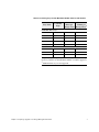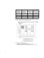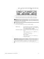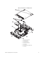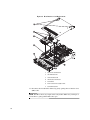
1
SGI InfiniteStorage 4000 Series and 5000 Series System Upgrade Guide (ISSM 10.83) 007-5878-001 August 2012 The information in this document supports the SGI InfiniteStorage 4000 series and 5000 series storage systems (ISSM 10.83). Refer to the table below to match your specific SGI InfiniteStorage product with the model numbers used in this document. SGI Model # TP9600H TP9700F IS4500F TP9600F IS4000H IS350 IS220 IS4100 IS-DMODULE16-Z IS-DMODULE60 IS4600 IS5012 IS5024 IS5060 IS-DMODULE12 & IS2212 (JBOD) IS-DMODULE24 & IS2224 (JBOD) IS-DMODULE60-SAS IS5512 IS5524 IS5560 Netapp Model 6091 6091 6091 3994 and 3992 3994 3992 1932 1333 DE1300 4900 FC4600 DE6900 7091 Netapp Compliance Model 1500 1500 1500 4600 4600 4600 3600 4600 4600 6900 1550 2600 2600 2600 DE1600 3650 5350 6600 3650 DE5600 5350 DE6600 5400 5400 5400 6600 3650 5350 6600 Notes FC HICs only 4Gb FC, 8Gb FC, HICs only FC and SAS HICs only Copyright information Copyright © 1994–2012 NetApp, Inc. All rights reserved. Printed in the U.S.A. No part of this document covered by copyright may be reproduced in any form or by any means— graphic, electronic, or mechanical, including photocopying, recording, taping, or storage in an electronic retrieval system—without prior written permission of the copyright owner. Software derived from copyrighted NetApp material is subject to the following license and disclaimer: THIS SOFTWARE IS PROVIDED BY NETAPP "AS IS" AND WITHOUT ANY EXPRESS OR IMPLIED WARRANTIES, INCLUDING, BUT NOT LIMITED TO, THE IMPLIED WARRANTIES OF MERCHANTABILITY AND FITNESS FOR A PARTICULAR PURPOSE, WHICH ARE HEREBY DISCLAIMED. IN NO EVENT SHALL NETAPP BE LIABLE FOR ANY DIRECT, INDIRECT, INCIDENTAL, SPECIAL, EXEMPLARY, OR CONSEQUENTIAL DAMAGES (INCLUDING, BUT NOT LIMITED TO, PROCUREMENT OF SUBSTITUTE GOODS OR SERVICES; LOSS OF USE, DATA, OR PROFITS; OR BUSINESS INTERRUPTION) HOWEVER CAUSED AND ON ANY THEORY OF LIABILITY, WHETHER IN CONTRACT, STRICT LIABILITY, OR TORT (INCLUDING NEGLIGENCE OR OTHERWISE) ARISING IN ANY WAY OUT OF THE USE OF THIS SOFTWARE, EVEN IF ADVISED OF THE POSSIBILITY OF SUCH DAMAGE. NetApp reserves the right to change any products described herein at any time, and without notice. NetApp assumes no responsibility or liability arising from the use of products described herein, except as expressly agreed to in writing by NetApp. The use or purchase of this product does not convey a license under any patent rights, trademark rights, or any other intellectual property rights of NetApp. RESTRICTED RIGHTS LEGEND: Use, duplication, or disclosure by the government is subject to restrictions as set forth in subparagraph (c)(1)(ii) of the Rights in Technical Data and Computer Software clause at DFARS 252.277-7103 (October 1988) and FAR 52-227-19 (June 1987) ii Copyright information Trademark information NetApp, the NetApp logo, Network Appliance, the Network Appliance logo, Akorri, ApplianceWatch, ASUP, AutoSupport, BalancePoint, BalancePoint Predictor, Bycast, Campaign Express, ComplianceClock, Cryptainer, CryptoShred, Data ONTAP, DataFabric, DataFort, Decru, Decru DataFort, DenseStak, Engenio, Engenio logo, E-Stack, FAServer, FastStak, FilerView, FlexCache, FlexClone, FlexPod, FlexScale, FlexShare, FlexSuite, FlexVol, FPolicy, GetSuccessful, gFiler, Go further, faster, Imagine Virtually Anything, Lifetime Key Management, LockVault, Manage ONTAP, MetroCluster, MultiStore, NearStore, NetCache, NOW (NetApp on the Web), Onaro, OnCommand, ONTAPI, OpenKey, PerformanceStak, RAID-DP, ReplicatorX, SANscreen, SANshare, SANtricity, SecureAdmin, SecureShare, Select, Service Builder, Shadow Tape, Simplicity, Simulate ONTAP, SnapCopy, SnapDirector, SnapDrive, SnapFilter, SnapLock, SnapManager, SnapMigrator, SnapMirror, SnapMover, SnapProtect, SnapRestore, Snapshot, SnapSuite, SnapValidator, SnapVault, StorageGRID, StoreVault, the StoreVault logo, SyncMirror, Tech OnTap, The evolution of storage, Topio, vFiler, VFM, Virtual File Manager, VPolicy, WAFL, Web Filer, and XBB are trademarks or registered trademarks of NetApp, Inc. in the United States, other countries, or both. IBM, the IBM logo, and ibm.com are trademarks or registered trademarks of International Business Machines Corporation in the United States, other countries, or both. A complete and current list of other IBM trademarks is available on the Web at www.ibm.com/legal/copytrade.shtml. Apple is a registered trademark and QuickTime is a trademark of Apple, Inc. in the U.S.A. and/or other countries. Microsoft is a registered trademark and Windows Media is a trademark of Microsoft Corporation in the U.S.A. and/or other countries. RealAudio, RealNetworks, RealPlayer, RealSystem, RealText, and RealVideo are registered trademarks and RealMedia, RealProxy, and SureStream are trademarks of RealNetworks, Inc. in the U.S.A. and/or other countries. All other brands or products are trademarks or registered trademarks of their respective holders and should be treated as such. NetApp, Inc. is a licensee of the CompactFlash and CF Logo trademarks. NetApp, Inc. NetCache is certified RealSystem compatible. Trademark information iii Table of Contents Chapter 1 Preparing to Upgrade Your Storage Management Software . . . . . . . . . . . . . . . . 1 Upgrading the Storage Management Software and the Controller Firmware . . . 1 Storage Management Software Packages. . . . . . . . . . . . . . . . . . . . . . . . . . . . . . . 3 Installation Options . . . . . . . . . . . . . . . . . . . . . . . . . . . . . . . . . . . . . . . . . . . . 5 Checking the Current Version of the Storage Management Software . . . . . 5 Supported Controller Trays and Controller-Drive Trays . . . . . . . . . . . . . . . . . . . 6 Maximum Number of Drives and Volumes for Controller-Drive Trays and Controller Trays . . . . . . . . . . . . . . . . . . . . . . . . . . . . . . . . . . . . . . . . . . . . . . . . . . 6 Supported Storage Array Configurations . . . . . . . . . . . . . . . . . . . . . . . . . . . . . . . 8 Chapter 2 Upgrading Trays in the Storage Array . . . . . . . . . . . . . . . . . . . . . . . . . . . . . . . . . . 9 Upgrading Options for Supported Trays . . . . . . . . . . . . . . . . . . . . . . . . . . . . . . 10 Upgrading Cache Memory . . . . . . . . . . . . . . . . . . . . . . . . . . . . . . . . . . . . . . . . . 10 Upgrading Cache Memory for the CE7900 Controller Tray . . . . . . . . . . . 11 Upgrading Cache Memory for the E2600 Controller-Drive Trays . . . . . . . 21 Upgrading Cache Memory for the E5400 Controller-Drive Trays . . . . . . . 39 Upgrading Host Adapters . . . . . . . . . . . . . . . . . . . . . . . . . . . . . . . . . . . . . . . . . . 59 Upgrading a Host Interface Card in the CE7900 Controller Tray . . . . . . . 59 Upgrading a Host Interface Card in the E2600 Controller-Drive Trays . . . 67 Upgrading a Host Interface Card in the E5400 Controller-Drive Trays . . . 83 Chapter 3 Using the Firmware Upgrade Utility . . . . . . . . . . . . . . . . . . . . . . . . . . . . . . . . . . 103 Chapter 4 Upgrade Instructions for the HP-UX OS . . . . . . . . . . . . . . . . . . . . . . . . . . . . . . 105 System Requirements for HPUX . . . . . . . . . . . . . . . . . . . . . . . . . . . . . . . . . . . 105 Installing the Storage Management Software on the HP-UX OS . . . . . . . . . . 106 Checking the Installation on the HP-UX OS . . . . . . . . . . . . . . . . . . . . . . . . . . 108 Uninstalling the Storage Management Software on the HP-UX OS . . . . . . . . 109 Table of Contents v Chapter 5 Upgrade Instructions for the Solaris OS . . . . . . . . . . . . . . . . . . . . . . . . . . . . . . . 111 Supported Components for Solaris. . . . . . . . . . . . . . . . . . . . . . . . . . . . . . . . . . 111 Installing the Storage Management Software on the Solaris OS . . . . . . . . . . . 113 Checking the Installation on the Solaris OS. . . . . . . . . . . . . . . . . . . . . . . . . . . 115 Uninstalling the Storage Management Software on the Solaris OS. . . . . . . . . 116 Chapter 6 Upgrade Instructions for the Linux OS. . . . . . . . . . . . . . . . . . . . . . . . . . . . . . . . 117 System Requirements for Linux. . . . . . . . . . . . . . . . . . . . . . . . . . . . . . . . . . . . 117 System Requirements for Linux with InfiniBand . . . . . . . . . . . . . . . . . . . . . . 120 Installing the Storage Management Software on the Linux OS . . . . . . . . . . . . 121 Checking the Installation on the Linux OS . . . . . . . . . . . . . . . . . . . . . . . . . . . 124 Uninstalling Storage Management Software on the Linux OS . . . . . . . . . . . . 125 Chapter 7 Upgrade Instructions for the Windows OS . . . . . . . . . . . . . . . . . . . . . . . . . . . . . 127 System Requirements for Windows Server 2003 and XP . . . . . . . . . . . . . . . . 127 System Requirements for Windows Server 2008, Hyper-V and Vista . . . . . . 130 Installing the Storage Management Software on the Windows OS . . . . . . . . . 132 Checking the Installation on the Windows OS. . . . . . . . . . . . . . . . . . . . . . . . . 136 Uninstalling Storage Management Software on the Windows OS . . . . . . . . . 136 Chapter 8 Upgrade Instructions for Asymmetric Logical Unit Access (ALUA) with the VMware OS . . . . . . . . . . . . . . . . . . . . . . . . . . . . . . . . . . . . . . . . . . . . . . . . . . . . . . 139 System Requirements for VMware . . . . . . . . . . . . . . . . . . . . . . . . . . . . . . . . . 139 Installing ALUA Support for VMware Versions ESX4.1U2, ESXi5.0, and Prior Versions . . . . . . . . . . . . . . . . . . . . . . . . . . . . . . . . . . . . . . . . . . . . . . . . . . . . . . 142 Installing ALUA Support for VMware Versions ESX4.1U3, ESXi5.0U1, and Subsequent Versions . . . . . . . . . . . . . . . . . . . . . . . . . . . . . . . . . . . . . . . . . . . . 143 Appendix A Boot Device Installation . . . . . . . . . . . . . . . . . . . . . . . . . . . . . . . . . . . . . . . . . . . . . . . . . . . . . . . 145 Boot Device Support . . . . . . . . . . . . . . . . . . . . . . . . . . . . . . . . . . . . . . . . . . . . 145 Installing the Boot Device . . . . . . . . . . . . . . . . . . . . . . . . . . . . . . . . . . . . . . . . 145 Storage Array and Host Preparation . . . . . . . . . . . . . . . . . . . . . . . . . . . . . 146 vi Table of Contents Preparing the Storage Array as a Boot Device . . . . . . . . . . . . . . . . . . . . . 146 Preparing the Host. . . . . . . . . . . . . . . . . . . . . . . . . . . . . . . . . . . . . . . . . . . 151 Completing the Installation Process . . . . . . . . . . . . . . . . . . . . . . . . . . . . . 151 Table of Contents vii viii Table of Contents Preparing to Upgrade Your Storage Management Software 1 The following table shows the supported upgrade paths for controller trays and controller-drive trays for storage management software version 10.83 and controller firmware version 7.83. Table 1 Supported Trays and Software Upgrade Paths Tray Name Installed Storage Management Software Version Installed Controller Firmware Version Controller-drive trays E2612, E2624, E2660 10.70 or later 7.70 or later CE4900 10.60 or later 7.60 or later E5412, E5424, E5460 10.80 or later 7.80 or later 10.30 or later 7.30 or later Controller tray CE7900, CE7922 NOTE If you are upgrading from controller firmware version 7.75.26, you must first upgrade to 7.75.28, and then upgrade to 7.83. All other supported upgrades are performed directly without an intermediate step. Upgrading the Storage Management Software and the Controller Firmware NOTE To make sure that your failover driver is compatible with the new hardware, firmware, and software, refer to the SANtricity™ ES Storage Manager Failover Drivers User Guide for Version 10.83. For the RHEL 6.1 and SLES operating systems, if you are setting up a configuration to support Asynchronous Logical Unit Access (ALUA), additional steps are required to install software patches. These steps are required for a successful upgrade to storage management software version 10.83 and controller firmware version 7.83. Perform the steps in order. You might find it helpful to print the Upgrade Checklist and refer to it as you work through the upgrade steps. 1. Make sure that the controller trays and the controller-drive trays in your storage array are compatible with the software level and the firmware level to which you are upgrading. 2. Check that the host bus adapters (HBAs), switches, driver versions, firmware levels, and specific hardware restrictions are supported. Chapter 1: Preparing to Upgrade Your Storage Management Software 1 NOTE Install all storage area network (SAN) hardware before you work with the storage management software. 3. Start the existing storage management software with the procedure for your operating system. 4. Check that the storage array has Optimal status. 5. Save and print the storage array profile from the current Array Management Window of the storage management software for each storage array. a. In the Array Management Window, select Monitor >> Report >> Storage Array Profile. b. Click Save As c. Select the All sections radio button. d. Type a file name in the File name text box. e. Click Save. The storage array profile is used for this information: — Configuration information that you might provide to your Technical Support representative — The current NVSRAM and controller firmware versions — The current environmental services module (ESM) firmware version 6. Locate the cache and processor memory size (MB) in the storage array profile, and record the listed size for later verification. 7. Locate the host interface in the storage array profile, and record the number listed in the Preferred ID area for each Fibre Channel interface for later verification. 8. Make sure that your storage array has the minimum system requirements for your operating system. See the system requirements topics for each operating system in this document. 9. Make sure that your failover driver is compatible with the new hardware, firmware, and software. Refer to the topics under SANtricity ES Storage Manager Failover Drivers User Guide for Version 10.83. NOTE Read the "dependence" section in the SANtricity ES Storage Manager readme.txt file. 10. Make sure that the current version of storage management software can be upgraded to SANtricity ES Storage Manager Version 10.83. 11. Install storage management software version 10.83 for your operating system (OS). Use the procedure for your OS to install the storage management software. 12. Make sure that the installation was successful. Use the procedure for your operating system to start the storage management software. 2 13. Check that the storage array has an Optimal status. If one or more managed devices has a Needs Attention status, contact your Technical Support representative. 14. If you determined from the storage array profile that the NVSRAM firmware, the controller firmware, or the ESM firmware is not the current version, download the compatible firmware. NOTE With the I/O Shipping feature, a storage array can use asymmetric logical unit access (ALUA). ALUA enables a controller tray or a controller-drive tray to service I/O requests through either controller in a duplex configuration. To use the I/O Shipping feature with VMware, you must take additional steps to update the VMware configuration. See Upgrade Instructions for Asymmetric Logical Unit Access (ALUA) with the VMware OS on page 139 for instructions. Storage Management Software Packages All storage management software packages are generally installed in the same directory on the same system, whether the system is the host or a separate storage management station. Table 2 Storage Management Software Packages Software Package Description and Usage SMclient This package contains the graphical user interface for managing the storage array. This package also contains an optional monitor service that sends alerts when a critical problem exists with the storage array. SMagent The storage management software that is installed only on a host machine to enable in-band management.1 SMruntime The operating system (OS) -specific storage management software that installs the appropriate Java runtime environment (JRE), which allows Java files to be displayed. Chapter 1: Preparing to Upgrade Your Storage Management Software 3 Software Package Description and Usage Redundant Dual Active Controller (RDAC)/Multi-Path Proxy (MPP) A multi-path failover driver, proprietary to NetApp, that is installed on Linux hosts. This software package manages the I/O paths into the controllers in the storage array. If a problem exists on the path or a failure occurs on one of the controllers, the driver automatically reroutes the request from the hosts to the other controller in the storage array. For information about other supported failover drivers for your operating system, refer to the topics under SANtricity ES Storage Manager Failover Drivers User Guide for Version 10.83. SMutil This package contains utilities that let the operating system recognize the volumes that you create in the storage array and to view the OS-specific device names for each volume. SMprovider The storage management software interface to the Volume Shadow Copy Service (VSS) and Virtual Disk Service (VDS) technologies (these technologies are included with Microsoft’s .NET framework). SMinstaller A package that installs the InstallAnywhere utility. 1 In-band management is a method for managing a storage array in which the controllers are managed from a storage management station attached to a host that is running host-agent software. The host-agent software receives communication from the storage management client software and passes it to the storage array controllers along the input/output (I/O) path. The controllers also use the I/O connections to send event information back to the storage management station through the host. NOTE The Microsoft Virtual Disk Service (VDS) and Volume Shadow Copy Service (VSS) providers are a part of the SANtricity ES Storage Manager package for the Windows Server 2003 OS and the Windows Server 2008 OS. 4 Installation Options Install only the packages that are required for the type of installation you are performing. Table 3 Installation Options and Related Software Packages Installation Option Typical installation SMruntime SMclient X X Storage management X station2 X Host station X A host station acting X as a storage management station (out-of-band management)3 Host with in-band management X X SMutil X RDAC Failover Driver1 SMagent X X X X X X X X 1 The RDAC/MPP failover driver is proprietary to NetApp and is available for download to the Linux OS. 2 The storage management station is a computer that runs storage management software that adds, monitors, and manages the storage arrays on a network. 3 Out-of-band management is a method to manage a storage array over the network through an Ethernet connection, from a storage management station that need not have an I/O path connection to the controllers. Checking the Current Version of the Storage Management Software The operating system-specific commands are listed below. To check the level of the current storage management software, type the command that corresponds to your operating system, and press Enter. The <package name> placeholder refers to the name of the software package that is installed. In the Linux operating system, type this command, and press Enter: rpm -qi <package name> In the Windows operating system, perform these tasks. a. Select Start >> Run. b. Type reged32, and press Enter. The Register Editor window appears. c. Select HKEY_LOCAL_MACHINE >> SOFTWARE >> STORAGE. The host software versions are listed under the storage directory. Chapter 1: Preparing to Upgrade Your Storage Management Software 5 Supported Controller Trays and Controller-Drive Trays Maximum Number of Drives and Volumes for Controller-Drive Trays and Controller Trays This section describes the supported controller trays and controller-drive trays. Table 4 Controller Trays and Controller-Drive Trays Term Description Controller tray A unit that contains one or two controllers, a battery (optional), and redundant cooling fans and power supplies. Controller trays do not contain environmental services modules (ESMs). Controller-drive tray A unit that contains up to 16 drives, redundant cooling fans and power supplies, and (depending on the model) one or two controllers. Controller-drive trays do not contain ESMs. Table 1 shows the controller-drive trays, the controller trays, and the maximum number of drives and the total number of volumes that are supported by each controller tray or controller-drive tray. The total numbers include drives or volumes that are contained in the controller-drive tray and in additional attached drive trays. Table 5 Supported Trays and the Maximum Number of Drives and Volumes Tray Name Controller Type Maximum Drives per Storage Array Maximum Volumes per Storage Array1 Controller-drive trays E2600 192 512 CE4900 1280 or 2560 112 1024 E5400 4096 or 8192 384 2048 Controller trays CE7900, CE7922 480 1 Snapshot (Legacy) repository volumes and Synchronous Mirroring repository volumes are included in the number of volumes supported. 2 Additional drive trays are not supported. The following table lists controller-drive trays and controller trays can co-exist in a storage network with hardware running storage management software version 10.83 and controller firmware version 7.83. They cannot, however, be upgraded to storage management software version 10.83 and controller firmware version 7.83. 6 Table 6 Co-existing Trays and the Maximum Number of Drives and Volumes Tray Name Controller Type Maximum Drives per Storage Array Maximum Volumes per Storage Array1 Controller-drive trays SHV2520 2880 (dual) 142 1024 SHV2600 2882 112 1024 SAT2700 2820-SATA 14 2 512 SAT2800 2822-SATA 112 512 CDE3994 3992 or 3994 112 1024 FC1250 4884 224 2048 FC1275 5884 224 2048 CE6998 6091 224 2048 Controller trays 1 Snapshot (Legacy) repository volumes and Synchronous Mirroring repository volumes are included in the number of volumes supported. 2 Additional drive trays are not supported. Chapter 1: Preparing to Upgrade Your Storage Management Software 7 Supported Storage Array Configurations 8 The drive tray is a unit that contains up to 16 drives, redundant cooling fans and power supplies, and one or two ESMs. Drive trays do not contain controllers. Table 7 Supported Drive Trays Mix of CE4900 and DE6600 DE1600/ DE5600 DE6600 Mix of DE1600/ DE5600 and DE6600 FC4600 DE6600 CE7900 CE7922 Maximum of 7 drive trays per loop pair, 28 drive trays total (total drives=480 maximum) Maximum of 2 drive trays per loop pair, 8 drive trays total (total drives=480 maximum) 6xDE6600+ Not 1xFC4600 supported or 1xDE6600+ 21xFC4600 (total drives=448 maximum) Not supported Not supported CE4900 Maximum of 6 drive trays Not supported Not supported Not supported Not supported Not supported E2600 Not supported Not supported Not supported Maximum Not total drives=192 of 2 drive supported maximum trays (total drives=180 maximum) E5400 Not supported Not supported Not supported Any mixture with total drives=384 maximum and total drive trays=16 maximum Upgrading Trays in the Storage Array 2 Keep these guidelines in mind before you upgrade trays in your storage array: Always back up your data to an external source before starting an upgrade procedure. Keep in mind that requirements for SFPs and cabling might change when you upgrade a host adapter. Refer to the Hardware Cabling Guide for a complete description of various cabling options. You can choose from these upgrade options: Upgrade cache memory Upgrade Host Adapters ATTENTION Possible loss of data access – Before you start any upgrade procedure, back up your data to an external source. Chapter 2: Upgrading Trays in the Storage Array 9 Upgrading Options for Supported Trays Table 1 Upgrading Options for Supported Trays Tray Name Tray Upgrading Option Upgrade Host Adapters CE7900 Upgrade 4-Gb/s FC to 8-Gb/s FC. Upgrade 1-Gb/s iSCSI to 10-Gb/s iSCSI. Install a second HIC (4-Gb/s FC, 8-Gb/s FC, 1-Gb/s iSCSI, 10-Gb/s iSCSI). E5400 Install a HIC in addition to the base host ports (8-Gb/s FC or 40-Gb/s InfiniBand). E2600 Install a HIC in addition to the base host ports (8-Gb/s FC, 1-Gb/s iSCSI, 10-Gb/s iSCSI, 6-Gb/s SAS). Upgrade Cache Memory CE7900 E5400 E2600 Upgrading Cache Memory Populate empty DIMM slots to increase capacity to 8-GB and add an additional cache backup memory device. Replace 1-GB DIMMS with 2-GB DIMMs to increase capacity to 16 GB and add an additional cache backup memory device. Replace 2-GB DIMMS with 4-GB DIMMs to increase capacity to 16 GB and add an additional cache backup memory device. Replace 2-GB DIMMS with 4-GB DIMMs to increase capacity to 12GB and add an additional cache backup memory device. Replace 4-GB DIMMS with 8-GB DIMMs to increase capacity to 24 GB and add an additional cache backup memory device. Replace 1-GB DIMMS with 2-GB DIMMs to increase capacity to 2 GB. Replace 2-GB DIMMS with 4-GB DIMMs to increase capacity to 4 GB. There are several option for upgrading cache memory in a controller-drive tray or a controller tray. 10 Each controller canister in the CE7900 controller tray has two sockets for cache memory DIMMs and a cache backup memory device. Use this procedure to add a cache memory DIMM, if the space is available, or upgrade an existing cache memory DIMM and, if necessary, add a cache backup memory device. Upgrading Cache Memory for the CE7900 Controller Tray Each controller canister in the E5400 controller-drive tray has two sockets for cache memory DIMMs and a cache backup memory device. Use this procedure to upgrade existing cache memory DIMMs and, if necessary, add a cache backup memory device. Each controller canister in the E2600 controller-drive tray has one socket for cache memory DIMMs and a cache backup memory device. Use this procedure to upgrade existing cache memory DIMM and, if necessary, add a cache backup memory device. Before you start this procedure, gather antistatic protection, cache memory DIMMs, and, if necessary, cache backup memory devices. Perform each of the following tasks in order. 1. Remove the controller canisters from the controller-drive tray or a controller tray. 2. Upgrade the cache memory DIMM. 3. Upgrade the Cache Backup Memory Device. 4. Reinstall the controller canisters from the controller-drive tray or the controller tray. ATTENTION Data loss or corruption might result if the steps in this upgrade procedure are not followed correctly – You must upgrade the cache memory DIMMs and the cache backup memory devices in both controller canisters in the controller tray or the controller-drive tray. Otherwise, you receive event messages indicating that the controllers have mismatched and incompatible configurations. This event might cause the controllers to lock down. NOTE Do not perform this upgrade procedure with the power turned on. This procedure requires that you first set controller A offline to make sure that all of the data, which is currently in cache on both controller canisters, is successfully written to disk before the upgrade. Second, you will turn off the power to both controller canisters as described in the steps for "Removing a Controller Canister" on page 11. Removing a Controller Canister NOTE Before you remove the controller canisters, make sure that you set controller A to Offline, as described in the following steps, to ensure that all the data currently in the cache for controller A is successfully written to disk prior to the upgrade. This step also ensures that the data currently in the cache for controller B is successfully written to disk before you turn off the power to both controller canisters. ATTENTION Possible hardware damage – To prevent electrostatic discharge damage to the tray, use proper antistatic protection when handling tray components. Chapter 2: Upgrading Trays in the Storage Array 11 1. Gather support data about your updated storage array by using one of these methods: SANtricity ES From the Array Management Window toolbar, select Monitor >> Health >> Collect Support Data. Then name and specify a location on your system where you want to store the support bundle. Command line interface Enter the following command on the command line: save storageArray supportData This command gathers comprehensive support data about the storage array. For more information about this command, refer to Command Line Interface and Script Commands Programming Guide. Running this command can temporarily impact performance on your storage array. 2. Use the Locate function in the storage management software to identify the controller canisters to upgrade. 3. Put on antistatic protection. 4. Label each host interface cable, drive interface cable, and Ethernet cable that is attached to each controller canister so that you can reconnect the cables correctly after the controller canisters are reinstalled. ATTENTION Potential degraded performance – To prevent degraded performance, do not twist, fold, pinch, or step on the fiber-optic cables. Do not bend the fiber-optic cables tighter than a 5-cm (2-in.) radius. 5. 12 Stop all host I/O operations. 6. Use one of the following options to place controller A offline. SANtricity ES From the Hardware pane in the Array Management Window, right-click the picture of the controller, and select Advanced >> Place >> Offline. Command line interface Enter the following command on the command line: smCLI <DNS-network-name-or-IP-address> -c “set controller [a] availability=offline”; In this command, <DNS-network-name-or-IP-address> is the applicable address. ATTENTION Possible data loss or corruption – Wait for the blue Controller Service Action Allowed LED on controller A to come on before you turn off the power to either controller; otherwise, possible data loss or corruption might occur. 7. Turn off the Power switch on both of the controller canisters. 8. Wait until all LED and seven-segment display activity on the rear of the controller tray has stopped, and then unplug the power cords from both controller canisters, and set the power cords aside. 9. Disconnect all of the following cables from both controller canisters. — Host interface cables — Drive interface cables — Ethernet cables 10. Remove both controller canisters from the controller tray as shown in the following figures. a. Unlock and rotate the release handles out to release the controller canister. b. Using the release handles and your hands, pull the controller canister out of the controller tray. c. Set the controller canister on a flat, static-free surface with the thumbscrews that secure the top cover to the canister facing up. Chapter 2: Upgrading Trays in the Storage Array 13 Figure 1 Removing a Controller 1. Release Handles 2. Locking Mechanisms 3. Controller Canister 11. Remove the cover on both controller canisters. 14 a. Loosen the thumbscrews that secure the cover to the controller canister. b. Lift the cover off of the controller canister as shown in the following figures. Figure 2 Controller Top Cover, Internal Parts, and Faceplate 1. Cache Backup Memory Device Slot Locations 2. Cache Memory DIMM Slot Locations 12. Go to "Upgrading a Cache Memory DIMM in the CE7900 Controller Canister" on page 15. Upgrading a Cache Memory DIMM in the CE7900 Controller Canister If you are upgrading the cache memory DIMMs in one controller canister, you must increase the capacity of the cache memory DIMMs in the other controller canister in the CE7900 controller tray. You also must increase the capacity of the cache backup memory devices in both controller canisters. Make sure that the size of the cache memory DIMMs that you are upgrading in both controller canisters are of equal capacity. The following table lists the cache memory DIMM configurations. Chapter 2: Upgrading Trays in the Storage Array 15 Total Cache Number of Cache Capacity of Each Memory per Memory DIMMs Cache Memory Controller (GB) per Controller DIMM (GB) 1. Cache DIMM Slots Populated 4 4 1 2, 4, 5, 7 8 8 1 All 16 8 2 All 32 8 4 All Locate the cache memory DIMMs that you want to upgrade, or identify the location to add the new cache memory DIMMs. Refer to the following figure. Figure 3 Cache Memory DIMM Locations in the CE7900 Controller Tray 16 1. Cache Memory DIMM Slot 1 2. Cache Memory DIMM Slot 2 3. Cache Memory DIMM Slot 3 4. Cache Memory DIMM Slot 4 5. Cache Memory DIMM Slot 5 6. Cache Memory DIMM Slot 6 7. Cache Memory DIMM Slot 7 8. Cache Memory DIMM Slot 8 2. 3. Choose one of the following options: — To upgrade cache memory DIMM – Go to step 3. — To add an additional cache memory DIMM – Go to step 4. Remove the cache memory DIMMs from their slots on the controller card. Refer to the following figure. a. Pull back on each ejector handle to disengage the cache memory DIMM pins from the slot on the controller card. b. Lift the cache memory DIMM out of the slot. c. Place the cache memory DIMM that you removed on an a flat, static-free surface. Figure 4 Removing a Cache Memory DIMM 4. 1. Cache Memory DIMM 2. Ejector Handles Install the new cache memory DIMM. a. Align the new cache memory DIMM in the slot. b. Gently push down on the cache memory DIMM to seat the pins into the slot. The ejector handles rise up as the cache memory DIMM is inserted into the slot. When these handles are in the vertical position, the cache memory DIMM is fully engaged and is locked in place. Upgrading a Cache Backup Memory Device in the CE7900 Controller Canister 5. Repeat this procedure for the other controller canister. 6. Go to "Upgrading a Cache Backup Memory Device in the CE7900 Controller Canister" on page 17. The cache backup memory device provides a backup for the cache memory DIMM. The size of the cache backup memory device must equal the capacity of the cache memory DIMM. You must increase the size of the cache backup memory device in both controller canisters. The following table lists the cache backup memory device configurations. Chapter 2: Upgrading Trays in the Storage Array 17 Total Cache Number of Cache Capacity of Each Backup Memory Backup Memory Cache Backup Device per Devices per Memory Device Controller (GB) Controller (GB) 1. Cache Backup Memory Device Slots Populated 4 1 4 USB 3 8 2 4 USB 3, USB 4 16 4 4 All 32 4 8 All Locate the cache backup memory device that you want to upgrade, or identify the location to add the new cache backup memory device. Figure 5 Cache Backup Memory Device Locations in the CE7900 Controller Tray 2. 18 1. Cache Backup Memory Device Slot 1 2. Cache Backup Memory Device Slot 2 3. Cache Backup Memory Device Slot 3 4. Cache Backup Memory Device Slot 4 Choose one of the following options: — To upgrade cache backup memory device – Go to step 3. — To install an additional cache backup memory device – Go to step 4. 3. 4. Reinstalling the Controller Canister in the CE7900 Controller Tray Remove the cache backup memory device from the connector on the controller card. a. Gently pull back on the latch that secures one edge of the cache backup memory device to the connector on the controller card. b. Lift the cache backup memory device from the connector. Install the new cache backup memory device. a. Carefully align the cache backup memory device with the connector on the controller card so that the pins do not bend when you install the cache backup memory device. b. Install the cache backup memory device into an empty socket location by gently pressing down on the cache backup memory device until it snaps into place. 5. Repeat this procedure for the other controller canister. 6. Go to "Reinstalling the Controller Canister in the CE7900 Controller Tray" on page 19. 1. Reinstall the top covers on both controller canisters, and tighten all of the thumbscrews that secure the top cover. 2. Slide both controller canisters all of the way into the controller tray. Rotate the release handles in to lock each controller canister into place. 3. Reconnect all of the following cables to the appropriate ports on both controller canisters. — Ethernet cables — Host interface cables — Drive interface cables 4. Plug in the power cords to both of the controller canisters. 5. Turn on the Power switches on both of the controller canisters. Controller B comes up in Write-Through mode. Controller A comes up in an Offline state. 6. Bring controller A online. In the Array Management Window, right-click the controller, and then select Advanced >> Place >> Online, or use the following CLI command. set controller [a] availability=online; 7. Look at the LEDs on the controller canister to make sure that the controllers are rebooting correctly. Refer to the following figure for the locations of the LEDs. Chapter 2: Upgrading Trays in the Storage Array 19 Figure 6 Controller Service Action LEDs 1. Controller Service Action Allowed LED (Blue) 2. Controller Service Action Required LED (Amber) The LEDs come on and go off intermittently for approximately 60 seconds (possibly longer). The seven-segment display shows the sequence OS+ Sd+ blank- to indicate that the controller is performing Start-of-day (SOD) processing. After the controller successfully completes rebooting, the seven-segment display shows the tray ID matching the seven-segment display on the second controller. After this time, you can discover the controller canister with the new battery by using the storage management software. 8. 9. 20 Based on the LED status, perform one of these actions: — All of the Service Action Required LEDs are off, and the Array Management Window indicates an Optimal status – Go to step 11. — Any of the Contoller-Drive tray’s Service Action Required LEDs are on, or the Controller Service Action Required LED is on – Go to step 9. Perform one of the following actions (based on the Recovery Guru display): — The Recovery Guru displays the following message: REC_CACHE_BACKUP_DEVICE_INSUFFICIENT_CAPACITY – The controllers might require an additional power cycle to initialize the new cache backup memory devices. Turn off the Power switches on both controller canisters. Wait until all LED and seven-segment display activity has stopped, and then turn on the Power switches to both controller canisters. Go to step 10. — The Recovery Guru does not display an insufficient capacity message – Check that the controller canister has been installed correctly. Reinstall the controller canister if necessary. Go to step 10. 10. Did this action correct the problem? — Yes – Go to step 11. — No – If the problem is not resolved, contact your Technical Support representative. 11. Using the LEDs and the storage management software, check the status of the trays in the storage array. 12. Does any component have a Needs Attention status? — Yes – Click the Recovery Guru toolbar button in the Array Management Window, and complete the recovery procedure. If the problem is not resolved, contact your Technical Support representative. — No – Go to step 13. 13. Remove the antistatic protection. 14. Gather support data about your updated storage array by using one of these methods: SANtricity ES From the Array Management Window toolbar, select Monitor >> Health >> Collect Support Data. Then name and specify a location on your system where you want to store the support bundle. Command line interface Enter the following command on the command line: save storageArray supportData This command gathers comprehensive support data about the storage array. For more information about this command, refer to Command Line Interface and Script Commands Programming Guide. Running this command can temporarily impact performance on your storage array. Upgrading Cache Memory for the E2600 Controller-Drive Trays Before you start this procedure, gather antistatic protection, cache memory DIMMs, and cache backup memory devices. Perform each of the following tasks in order. 1. Choose the applicable task to remove the controller canisters: — Remove the controller canisters from the E2612 or E2624 controller-drive tray. — Remove the controller canisters from the E2660 controller-drive tray. The remaining tasks in this section are the same for the E2612, E2624, and E2660 controller-drive trays. 2. Upgrade the cache memory DIMM. 3. Upgrade the cache backup memory device. 4. Reinstall the controller canisters from the controller-drive tray. Chapter 2: Upgrading Trays in the Storage Array 21 5. Turn on power to the controller-drive tray. ATTENTION Data loss or corruption might result if the steps in this upgrade procedure are not followed correctly – You must upgrade the cache memory DIMMs and the cache backup memory devices in both controller canisters in the controller tray or the controller-drive tray. Otherwise, you receive event messages indicating that the controllers have mismatched and incompatible configurations. This event might cause the controllers to lock down. NOTE Do not perform this upgrade procedure with the power turned on. This procedure requires that you first set controller A offline to make sure that all of the data, which is currently in cache on both controller canisters, is successfully written to disk before the upgrade. After the cache memory data is written to disk, you must turn off the power to both controller canisters. Removing the Controller Canisters from the E2612 or E2624 Controller-Drive Tray NOTE Before you remove the controller canisters, make sure that you set controller A offline, as described in the following steps, to make sure that all the data currently in the cache in controller A is successfully written to disk before the upgrade. This step also makes sure that the data currently in the cache in controller B is successfully written to disk before you turn off the power to both of the controller canisters. ATTENTION Possible hardware damage – To prevent electrostatic discharge damage to the tray, use proper antistatic protection when handling tray components. 1. Gather support data about your storage array by using one of these methods: SANtricity ES From the Array Management Window toolbar, select Monitor >> Health >> Collect Support Data. Then name and specify a location on your system where you want to store the support bundle. Command line interface Enter the following command on the command line: save storageArray supportData This command gathers comprehensive support data about the storage array. For more information about this command, refer to Command Line Interface and Script Commands Programming Guide. Running this command can temporarily impact performance on your storage array. 2. 22 Use the Locate function in the storage management software to identify the controller canisters to upgrade as shown in the following figure. Figure 7 Controller A Position in the E2600 Controller-Drive Tray 3. Put on antistatic protection. 4. Label each cable that is attached to each controller canister so that you can reconnect each cable correctly after the controller canisters are reinstalled. ATTENTION Possible degraded performance – To prevent degraded performance, do not twist, fold, pinch, or step on the fiber-optic cables. Do not bend the fiber-optic cables tighter than a 5-cm (2-in.) radius. 5. Stop all host I/O operations. 6. Use one of the following options to place controller A offline. SANtricity ES From the Hardware pane in the Array Management Window, right-click the picture of the controller, and select Advanced >> Place >> Offline. Command line interface Enter the following command on the command line: smCLI <DNS-network-name-or-IP-address> -c “set controller [a] availability=offline”; In this command, <DNS-network-name-or-IP-address> is the applicable address. ATTENTION Possible data loss or corruption – Wait for the blue Controller Service Action Allowed LED on controller A to come on before you turn off the power to either controller; otherwise, possible data loss or corruption might occur. Chapter 2: Upgrading Trays in the Storage Array 23 Figure 8 Controller LEDs 7. 1. Host Link 1 Service Action Required LED (Amber) 2. Host Link 2 Service Action Required LED (Amber) 3. Battery Service Action Required LED (Amber) 4. Controller Service Action Allowed LED (Blue) 5. Controller Service Action Required LED (Amber) Turn off the Power switch on each of the power-fan canisters, and wait until all LED and seven-segment display activity on the rear of the controller-drive tray has stopped. Figure 9 Power Supplies in the E2600 Controller-Drive Tray 8. 1. Power-Fan Canister for Controller A 2. Power-Fan Canister for Controller B Disconnect the following cables from both controller canisters. — Host interface cables — Drive interface cables — Ethernet cables If fiber-optic cables are present, you can lift the two release levers and partially remove the controller canister. Opening these release levers makes it easier to press down on the fiber-optic cable release tab. 24 9. Remove both controller canisters from the controller-drive tray as shown in the following figure. a. Unlock and pull out the release levers to release the controller canisters. b. Using the release levers and your hands, pull both controller canisters out of the controller-drive tray. c. Set each controller canister on a flat, static-free surface near the controller-drive tray. Position the controller canister so that you can access the top cover. NOTE The following figure shows controller A being removed. You remove controller B in the same way. Figure 10 Removing a Controller Canister 1. Release Levers 2. Controller Canister 10. Prepare the controller air blocker by removing it from its packaging and folding it inward at right angles so it is ready to insert into the open controller slot. Chapter 2: Upgrading Trays in the Storage Array 25 Figure 11 Controller Air Blocker 11. Insert the controller air blocker into the open controller slot to make sure that the correct airflow is maintained. Figure 12 Inserting the Controller Air Blocker into the Open Controller Slot 12. On each controller canister, press down on both of the top cover latch buttons, and slide the top covers to the rear as shown in the following figure. 26 Figure 13 Controller Cover and Internal Parts 1. Top Cover Latch Buttons 13. Remove the top cover from both controller canisters. 14. Go to "Upgrading the Cache Memory DIMM in the E2600 Controller-Drive Trays" on page 33. Removing the Controller Canisters from the E2660 Controller-Drive Tray NOTE Before you remove the controller canisters, make sure that you set controller A offline, as described in the following steps, to make sure that all the data currently in the cache in controller A is successfully written to disk before the upgrade. This step also makes sure that the data currently in the cache in controller B is successfully written to disk before you turn off the power to both of the controller canisters. Chapter 2: Upgrading Trays in the Storage Array 27 ATTENTION Possible hardware damage – To prevent electrostatic discharge damage to the tray, use proper antistatic protection when handling tray components. 1. Gather support data about your storage array by using one of these methods: SANtricity ES From the Array Management Window toolbar, select Monitor >> Health >> Collect Support Data. Then name and specify a location on your system where you want to store the support bundle. Command line interface Enter the following command on the command line: save storageArray supportData This command gathers comprehensive support data about the storage array. For more information about this command, refer to Command Line Interface and Script Commands Programming Guide. Running this command can temporarily impact performance on your storage array. 2. Use the Locate function in the storage management software to identify the controller canisters to upgrade as shown in the following figure. Figure 14 Controller A Position in the E2600 Controller-Drive Tray 28 1. Controller A 2. Controller B 3. Put on antistatic protection. 4. Label each cable that is attached to each controller canister so that you can reconnect each cable correctly after the controller canisters are reinstalled. ATTENTION Possible degraded performance – To prevent degraded performance, do not twist, fold, pinch, or step on the fiber-optic cables. Do not bend the fiber-optic cables tighter than a 5-cm (2-in.) radius. 5. Stop all host I/O operations. 6. Use one of the following options to place controller A offline. SANtricity ES From the Hardware pane in the Array Management Window, right-click the picture of the controller, and select Advanced >> Place >> Offline. Command line interface Enter the following command on the command line: smCLI <DNS-network-name-or-IP-address> -c “set controller [a] availability=offline”; In this command, <DNS-network-name-or-IP-address> is the applicable address. ATTENTION Possible data loss or corruption – Wait for the blue Controller Service Action Allowed LED on controller A to come on before you turn off the power to either controller; otherwise, possible data loss or corruption might occur. Figure 15 Controller LEDs 7. 1. Controller Service Action Allowed LED (Blue) 2. Controller Service Action Required LED (Amber) Turn off the Power switch on each of the power-fan canisters, and wait until all LED and seven-segment display activity on the rear of the controller-drive tray has stopped. Chapter 2: Upgrading Trays in the Storage Array 29 Figure 16 Power Supplies in the E2600 Controller-Drive Tray 8. 1. Power-Fan Canister for Controller A 2. Power-Fan Canister for Controller B Disconnect the following cables from both controller canisters. — Host interface cables — Drive interface cables — Ethernet cables If fiber-optic cables are present, you can lift the two release levers and partially remove the controller canister. Opening these release levers makes it easier to press down on the fiber-optic cable release tab. 9. Remove both controller canisters from the controller-drive tray as shown in the following figure. a. Unlock and pull out the release levers to release the controller canisters. b. Using the release levers and your hands, pull both controller canisters out of the controller-drive tray. c. Set each controller canister on a flat, static-free surface near the controller-drive tray. Position the controller canister so that you can access the top cover. NOTE The following figure shows controller A being removed. You remove controller B in the same way. 30 Figure 17 Removing a Controller Canister 1. Release Levers 2. Controller Canister 10. Prepare the controller air blocker by removing it from its packaging and folding it inward at right angles so it is ready to insert into the open controller slot. Chapter 2: Upgrading Trays in the Storage Array 31 Figure 18 Controller Air Blocker 11. Insert the controller air blocker into the open controller slot to make sure that the correct airflow is maintained. Figure 19 Inserting the Controller Air Blocker into the Open Controller Slot 12. On each controller canister, press down on both of the top cover latch buttons, and slide the top covers to the rear as shown in the following figure. 32 Figure 20 Controller Cover and Internal Parts 1. Top Cover Latch Buttons 13. Remove the top cover from both controller canisters. 14. Go to "Upgrading the Cache Memory DIMM in the E2600 Controller-Drive Trays" on page 33. Upgrading the Cache Memory DIMM in the E2600 Controller-Drive Trays If you are upgrading the cache memory DIMM in one controller canister, you must increase the capacity of the cache memory DIMM in the other controller canister in the E2600 controller-drive tray. You also must increase the capacity of the cache backup memory devices in both controller canisters. 1. Locate the cache memory DIMM shown in the following figure. Chapter 2: Upgrading Trays in the Storage Array 33 Figure 21 Cache Memory DIMM Slot – Top View 1. 2. 34 Cache Memory DIMM Slot Remove the cache memory DIMM from the slot on the controller card shown in the following figure. a. Pull back on each ejector handle to disengage the cache memory DIMM pins from the slot on the controller card. b. Lift the cache memory DIMM out of the slot. c. Place the cache memory DIMM that you removed on a flat, static-free surface. Figure 22 Removing a Cache Memory DIMM 3. 1. Cache Memory DIMM 2. Ejector Handles Install the new cache memory DIMM. a. Align the new cache memory DIMM in the slot. b. Gently push down on the cache memory DIMM to seat the pins into the slot. The ejector handles rise up as the cache memory DIMM is inserted into the slot. When these ejector handles are in the vertical position, the cache memory DIMM is fully engaged and is locked in place. 4. Repeat this procedure for the other controller canister. 5. Go to "Upgrading the Cache Backup Memory Device in the E2600 Controller-Drive Trays" on page 36. Chapter 2: Upgrading Trays in the Storage Array 35 Upgrading the Cache Backup Memory Device in the E2600 Controller-Drive Trays The cache backup memory device provides a backup for the cache memory DIMM. The size of the cache backup memory device might be greater than or equal to the capacity of the cache memory DIMM. You must increase the size of the cache backup memory device in both controller canisters. 1. Locate the cache backup memory device as shown in the following figure. Figure 23 Cache Backup Memory Device – Top View 1. 2. 36 Cache Backup Memory Device Remove the cache backup memory device from the slot. a. Release the cache backup memory device by gently pushing the memory farther into the slot. The slot releases the cache backup memory device and pushes the memory out of the slot. b. Carefully pull the cache backup memory device free from the slot. 3. Reinstalling the Controller Canister in the E2600 Controller-Drive Trays Turning On Power to the Controller Canisters in the E2600 Controller-Drive Trays Install the new cache backup memory device. a. Unwrap the new cache backup memory device. b. Install the new cache backup memory device into the empty slot location by pressing the cache backup memory device into the slot until it is fully seated. 4. Repeat this procedure for the other controller canister. 5. Go to "Reinstalling the Controller Canister in the E2600 Controller-Drive Trays." 1. Reinstall the top covers on both controller canisters by sliding them forward until the top cover latch buttons click. 2. Slide each controller canister all the way into the controller-drive tray. Rotate the release levers towards the center of the controller canister to lock that component into place. 3. Reconnect the following cables to the appropriate ports on both controller canisters. — Ethernet cables — Host interface cables — Drive interface cables 4. Go to "Turning On Power to the Controller Canisters in the E2600 Controller-Drive Trays." 1. Turn on the Power switches on both of the power-fan canisters. Controller B comes up in Write-Through mode. Controller A comes up in an Offline state. 2. Use one of the following options to place controller A online. SANtricity ES From the Hardware pane in the Array Management Window, right-click the picture of the controller, and select Advanced >> Place >> Online. Command line interface Enter the following command on the command line: smCLI <DNS-network-name-or-IP-address> -c “set controller [a] availability=online”; In this command, <DNS-network-name-or-IP-address> is the applicable address. Chapter 2: Upgrading Trays in the Storage Array 37 3. Look at the LEDs on both controller canisters to make sure that the controllers are booting correctly. The seven-segment display shows the sequence OS+ Sd+ blank- to indicate that the controller is performing Start-of-day (SOD) processing. After the controller successfully completes rebooting, the seven-segment display shows the tray ID matching the seven-segment display on the second controller. After this time, you can discover the controllers by using the storage management software. Figure 24 Controller LEDs 4. 5. 6. 38 1. Host Link 1 Service Action Required LED (Amber) 2. Host Link 2 Service Action Required LED (Amber) 3. Battery Service Action Required LED (Amber) 4. Controller Service Action Allowed LED (Blue) 5. Controller Service Action Required LED (Amber) Based on the LED status, perform one of these actions: — All of the Service Action Required LEDs are off, and the Array Management Window indicates an Optimal status – Go to step 11. — Any of the controller-drive tray’s Service Action Required LEDs are on, or the Controller Service Action Required LED is on – Go to step 5. Based on the Recovery Guru display, perform one of the following actions: — The Recovery Guru displays the following message: REC_CACHE_BACKUP_DEVICE_INSUFFICIENT_CAPACITY – The controllers might require an additional power cycle to initialize the new cache backup memory devices. Turn off the Power switches on both controller canisters. Wait until all LED and seven-segment display activity has stopped, and then turn on the Power switches on both power-fan canisters. Go to step 10. — The Recovery Guru does not display an insufficient capacity message – Check that the controller canister has been installed correctly. Reinstall the controller canister if necessary. Go to step 6. Did this action correct the problem? — Yes – Go to step 11. — No – If the problem is not resolved, contact your Technical Support representative. 7. Using the LEDs and the storage management software, check the status of the trays in the storage array. 8. Does any component have a Needs Attention status? 9. — Yes – Click the Recovery Guru toolbar button in the Array Management Window, and complete the recovery procedure. If the problem is not resolved, contact your Technical Support representative. — No – Go to step 13. Remove the antistatic protection. 10. Gather support data about your updated storage array by using one of these methods: SANtricity ES From the Array Management Window toolbar, select Monitor >> Health >> Collect Support Data. Then name and specify a location on your system where you want to store the support bundle. Command line interface Enter the following command on the command line: save storageArray supportData This command gathers comprehensive support data about the storage array. For more information about this command, refer to Command Line Interface and Script Commands Programming Guide. Running this command can temporarily impact performance on your storage array. Upgrading Cache Memory for the E5400 Controller-Drive Trays Before you start this procedure, gather antistatic protection, cache memory DIMMs, and cache backup memory devices. Perform each of the following tasks in order. 1. Choose the applicable task to remove the controller canisters: — Remove the controller canisters from the E5412 or E5424 controller-drive tray. — Remove the controller canisters from the E5460 controller-drive tray. The remaining tasks in this section are the same for the E5412, E5424, and E5460 controller-drive trays. 2. Upgrade the cache memory DIMM. 3. Upgrade the cache backup memory device. 4. Reinstall the controller canisters from the controller-drive tray. 5. Turn on power to the controller-drive tray. Chapter 2: Upgrading Trays in the Storage Array 39 ATTENTION Data loss or corruption might result if the steps in this upgrade procedure are not followed correctly – You must upgrade the cache memory DIMMs and the cache backup memory devices in both controller canisters in the controller tray or the controller-drive tray. Otherwise, you receive event messages indicating that the controllers have mismatched and incompatible configurations. This event might cause the controllers to lock down. NOTE Do not perform this upgrade procedure with the power turned on. This procedure requires that you first set controller A offline to make sure that all of the data, which is currently in cache on both controller canisters, is successfully written to disk before the upgrade. After the cache memory data is written to disk, you must turn off the power to both controller canisters. Removing the Controller Canisters from the E5412 or E5424 Controller-Drive Tray NOTE Before you remove the controller canisters, make sure that you set controller A offline, as described in the following steps, to make sure that all the data currently in the cache in controller A is successfully written to disk before the upgrade. This step also makes sure that the data currently in the cache in controller B is successfully written to disk before you turn off the power to both of the controller canisters. ATTENTION Possible hardware damage – To prevent electrostatic discharge damage to the tray, use proper antistatic protection when handling tray components. 1. Gather support data about your storage array by using one of these methods: SANtricity ES From the Array Management Window toolbar, select Monitor >> Health >> Collect Support Data. Then name and specify a location on your system where you want to store the support bundle. Command line interface Enter the following command on the command line: save storageArray supportData This command gathers comprehensive support data about the storage array. For more information about this command, refer to Command Line Interface and Script Commands Programming Guide. Running this command can temporarily impact performance on your storage array. 2. 40 Use the Locate function in the storage management software to identify the controller canisters to upgrade as shown in the following figure. Figure 25 Controller Positions in the E5412 Controller-Drive Tray and the E5424 Controller-Drive Tray 1. Controller A 3. Put on antistatic protection. 4. Label each cable that is attached to each controller canister so that you can reconnect each cable correctly after the controller canisters are reinstalled. ATTENTION Possible degraded performance – To prevent degraded performance, do not twist, fold, pinch, or step on the fiber-optic cables. Do not bend the fiber-optic cables tighter than a 5-cm (2-in.) radius. 5. Stop all host I/O operations. 6. Use one of the following options to place controller A offline. SANtricity ES From the Hardware pane in the Array Management Window, right-click the picture of the controller, and select Advanced >> Place >> Offline. Command line interface Enter the following command on the command line: smCLI <DNS-network-name-or-IP-address> -c “set controller [a] availability=offline”; In this command, <DNS-network-name-or-IP-address> is the applicable address. ATTENTION Possible data loss or corruption – Wait for the blue Controller Service Action Allowed LED on controller A to come on before you turn off the power to either controller; otherwise, possible data loss or corruption might occur. Chapter 2: Upgrading Trays in the Storage Array 41 Figure 26 Controller LEDs 7. 1. Host Link 1 Service Action Required LED (Amber) 2. Host Link 2 Service Action Required LED (Amber) 3. Battery Service Action Required LED (Amber) 4. Controller Service Action Allowed LED (Blue) 5. Controller Service Action Required LED (Amber) Turn off the Power switch on each of the power-fan canisters, and wait until all LED and seven-segment display activity on the rear of the controller-drive tray has stopped. Figure 27 Power Switches in the E5412 Controller-Drive Tray or the E5424 Controller-Drive Tray 1. 8. Power Switch for Controller A Disconnect the following cables from both controller canisters. — Host interface cables — Drive interface cables — Ethernet cables If fiber-optic cables are present, you can lift the two release levers and partially remove the controller canister. Opening these release levers makes it easier to press down on the fiber-optic cable release tab. 42 9. Remove both controller canisters from the controller-drive tray as shown in the following figure. a. Unlock and pull out the release levers to release the controller canisters. b. Using the release levers and your hands, pull both controller canisters out of the controller-drive tray. c. Set each controller canister on a flat, static-free surface near the controller-drive tray. Position the controller canister so that you can access the top cover. NOTE The following figure shows controller A being removed. You remove controller B in the same way. Figure 28 Removing a Controller Canister 1. Release Levers 2. Controller Canister 10. Prepare the controller air blocker by removing it from its packaging and folding it inward at right angles so it is ready to insert into the open controller slot. Chapter 2: Upgrading Trays in the Storage Array 43 Figure 29 Controller Air Blocker 11. Insert the controller air blocker into the open controller slot to make sure that the correct airflow is maintained. Figure 30 Inserting the Controller Air Blocker into the Open Controller Slot 12. On each controller canister, press down on both of the top cover latch buttons, and slide the top covers to the rear as shown in the following figure. 44 Figure 31 Controller Cover and Internal Parts 1. Top Cover Latch Buttons 13. Remove the top cover from both controller canisters. 14. Go to "Upgrading the Cache Memory DIMM in the E5400 Controller-Drive Trays" on page 52. Chapter 2: Upgrading Trays in the Storage Array 45 Removing the Controller Canisters from the E5460 Controller-Drive Tray NOTE Before you remove the controller canisters, make sure that you set controller A offline, as described in the following steps, to make sure that all the data currently in the cache in controller A is successfully written to disk before the upgrade. This step also makes sure that the data currently in the cache in controller B is successfully written to disk before you turn off the power to both of the controller canisters. ATTENTION Possible hardware damage – To prevent electrostatic discharge damage to the tray, use proper antistatic protection when handling tray components. 1. Gather support data about your storage array by using one of these methods: SANtricity ES From the Array Management Window toolbar, select Monitor >> Health >> Collect Support Data. Then name and specify a location on your system where you want to store the support bundle. Command line interface Enter the following command on the command line: save storageArray supportData This command gathers comprehensive support data about the storage array. For more information about this command, refer to Command Line Interface and Script Commands Programming Guide. Running this command can temporarily impact performance on your storage array. 2. 46 Use the Locate function in the storage management software to identify the controller canisters to upgrade as shown in the following figure. Figure 32 Controller Positions in the E5460 Controller-Drive Tray 1. Controller A 2. Controller B 3. Put on antistatic protection. 4. Label each cable that is attached to each controller canister so that you can reconnect each cable correctly after the controller canisters are reinstalled. ATTENTION Possible degraded performance – To prevent degraded performance, do not twist, fold, pinch, or step on the fiber-optic cables. Do not bend the fiber-optic cables tighter than a 5-cm (2-in.) radius. 5. Stop all host I/O operations. 6. Use one of the following options to place controller A offline. SANtricity ES From the Hardware pane in the Array Management Window, right-click the picture of the controller, and select Advanced >> Place >> Offline. Command line interface Enter the following command on the command line: smCLI <DNS-network-name-or-IP-address> -c “set controller [a] availability=offline”; In this command, <DNS-network-name-or-IP-address> is the applicable address. Chapter 2: Upgrading Trays in the Storage Array 47 ATTENTION Possible data loss or corruption – Wait for the blue Controller Service Action Allowed LED on controller A to come on before you turn off the power to either controller; otherwise, possible data loss or corruption might occur. Figure 33 Controller LEDs 7. 1. Controller Service Action Allowed LED (Blue) 2. Controller Service Action Required LED (Amber) Turn off the Power switch on each of the power-fan canisters, and wait until all LED and seven-segment display activity on the rear of the controller-drive tray has stopped. Figure 34 Power Switches on the E5460 Controller-Drive Tray 8. 1. Power Switch for Controller A 2. Power Switch for Controller B Disconnect the following cables from both controller canisters. — Host interface cables — Drive interface cables — Ethernet cables If fiber-optic cables are present, you can lift the two release levers and partially remove the controller canister. Opening these release levers makes it easier to press down on the fiber-optic cable release tab. 48 9. Remove both controller canisters from the controller-drive tray as shown in the following figure. a. Unlock and pull out the release levers to release the controller canisters. b. Using the release levers and your hands, pull both controller canisters out of the controller-drive tray. c. Set each controller canister on a flat, static-free surface near the controller-drive tray. Position the controller canister so that you can access the top cover. NOTE The following figure shows controller A being removed. You remove controller B in the same way. Figure 35 Removing and Reinstalling a Controller Canister 1. Release Lever 2. Controller Canister 10. Prepare the controller air blocker by removing it from its packaging and folding it inward at right angles so it is ready to insert into the open controller slot. Chapter 2: Upgrading Trays in the Storage Array 49 Figure 36 Controller Air Blocker 11. Insert the controller air blocker into the open controller slot to make sure that the correct airflow is maintained. 50 Figure 37 Inserting the Controller Air Blocker into the Open Controller Slot 12. On each controller canister, press down on both of the top cover latch buttons, and slide the top covers to the rear as shown in the following figure. Chapter 2: Upgrading Trays in the Storage Array 51 Figure 38 Controller Cover and Internal Parts 1. Top Cover Latch Buttons 13. Remove the top cover from both controller canisters. 14. Go to "Upgrading the Cache Memory DIMM in the E5400 Controller-Drive Trays" on page 52. Upgrading the Cache Memory DIMM in the E5400 Controller-Drive Trays If you are upgrading the cache memory DIMMs in one controller canister, you must increase the capacity of the cache memory DIMMs in the other controller canister. You also must increase the capacity of the cache backup memory device in both controller canisters if you upgrade the cache memory DIMMs from 6 GB to 12 GB. Make sure that the sizes of the cache memory DIMMs to which you are upgrading in both controller canisters are of equal capacity. The following table lists the cache memory DIMM configurations. 52 Total Cache Memory per Controller 1. Number of Cache Capacity of Each Memory DIMMs Cache Memory per Controller DIMM 6 GB 3 12 GB 3 24 GB 3 2 Cache DIMM Slots Populated 1, 2, 3 1, 2, 3 48 1, 2, 3 Locate the cache memory DIMM shown in the following figure. Figure 39 Cache Memory DIMM Slots – Top View Chapter 2: Upgrading Trays in the Storage Array 1. Cache Memory DIMM Slot 1 2. Cache Memory DIMM Slot 2 53 2. Remove the cache memory DIMM from the slot on the controller card shown in the following figure. a. Pull back on each ejector handle to disengage the cache memory DIMM pins from the slot on the controller card. b. Lift the cache memory DIMM out of the slot. c. Place the cache memory DIMM that you removed on a flat, static-free surface. Figure 40 Removing a Cache Memory DIMM 3. 1. Cache Memory DIMM 2. Ejector Handles Install the new cache memory DIMM. a. Align the new cache memory DIMM in the slot. b. Gently push down on the cache memory DIMM to seat the pins into the slot. The ejector handles rise up as the cache memory DIMM is inserted into the slot. When these ejector handles are in the vertical position, the cache memory DIMM is fully engaged and is locked in place. 4. 5. Upgrading the Cache Backup Memory Device in the E5400 Controller-Drive Trays 54 Repeat this procedure for the other controller canister. Perform one of these actions: — If you upgraded your cache memory DIMMs from 6 GB to 12 GB, go to Upgrading the Cache Backup Memory Device in the E5400 Controller-Drive Trays on page 54. — If you are upgrading your cache memory DIMMs from 12 GB to 24 GB, you do not need to install an additional cache backup memory device. Go to "Reinstalling the Controller Canister in the E5400 Controller-Drive Tray" on page 57. The cache backup memory device provides a backup for the cache memory DIMMs. If you are adding an additional cache backup memory device in one controller canister, you also must add an additional cache backup memory device in the other controller canister. Follow this procedure only if you upgraded the cache memory DIMMs from 6 GB to 12 GB. If you upgraded the cache memory DIMMs from 12 GB to 24 GB, you can skip this procedure. NOTE On the E5460 controller canister, the total cache backup memory per controller does not equal the total cache memory per controller. The following table lists the cache backup memory device configurations. Total Cache Memory per Controller Number of Cache Backup Memory Devices per Controller Cache Backup Memory Device Slots Populated 6 GB 1 1 12 GB 2 1, 2 24 GB 2 1, 2 NOTE Although the physical capacity of each cache backup memory device is 8 GB, only 4 GB of each device is used for nonvolatile cache memory offload. The remainder is used for other purposes, such as storing controller firmware images. The storage array profile displays the capacity of each cache backup memory device as 4 GB. Chapter 2: Upgrading Trays in the Storage Array 55 1. Identify the location to add the new cache backup memory device as shown in the following figure. Figure 41 Cache Backup Memory – Top View 1. Cache Backup Memory Device Slot 1 Cache Backup Memory Device Slot 2 2. 56 Install the new cache backup memory device. a. Unwrap the new cache backup memory device. b. Install the new cache backup memory device into the empty slot location by pressing the tab and sliding the cache backup memory device on the alignment post until it is fully seated. 3. Repeat this procedure for the other controller canister. 4. Go to "Reinstalling the Controller Canister in the E5400 Controller-Drive Tray" on page 57. Reinstalling the Controller Canister in the E5400 Controller-Drive Tray Turning On Power to the Controller Canisters in the E5400 Controller-Drive Tray 1. Reinstall the top covers on both controller canisters by sliding them forward until the top cover latch buttons click. 2. Slide each controller canister all the way into the controller-drive tray. Rotate the release levers towards the center of the controller canister to lock that component into place. 3. Reconnect the following cables to the appropriate ports on both controller canisters. — Ethernet cables — Host interface cables — Drive interface cables 4. Go to "Turning On Power to the Controller Canisters in the E5400 Controller-Drive Tray" on page 57. 1. Turn on the Power switches on both of the power-fan canisters. Controller B comes up in Write-Through mode. Controller A comes up in an Offline state. 2. Use one of the following options to bring controller A online. SANtricity ES From the Hardware pane in the Array Management Window, right-click the picture of the controller, and select Advanced >> Place >> Online. Command line interface Enter the following command on the command line: smCLI <DNS-network-name-or-IP-address> -c “set controller [a] availability=online”; In this command, <DNS-network-name-or-IP-address> is the applicable address. 3. Look at the LEDs on both controller canisters to make sure that the controllers are booting correctly. The seven-segment display shows the sequence OS+ Sd+ blank- to indicate that the controller is performing Start-of-day (SOD) processing. After the controller successfully completes rebooting, the seven-segment display shows the tray ID matching the seven-segment display on the second controller. After this time, you can discover the controllers by using the storage management software. Chapter 2: Upgrading Trays in the Storage Array 57 Figure 42 Controller LEDs 4. 5. 6. 58 1. Host Link 1 Service Action Required LED (Green) 2. Host Link 2 Service Action Required LED (Green) 3. Battery Service Action Required LED (Amber) 4. Controller Service Action Allowed LED (Blue) 5. Controller Service Action Required LED (Amber) Based on the LED status, perform one of these actions: — All of the Service Action Required LEDs are off, and the Array Management Window indicates an Optimal status – Go to step 11. — Any of the controller-drive tray’s Service Action Required LEDs are on, or the Controller Service Action Required LED is on – Go to step 5. Based on the Recovery Guru display, perform one of the following actions: — The Recovery Guru displays the following message: REC_CACHE_BACKUP_DEVICE_INSUFFICIENT_CAPACITY – The controllers might require an additional power cycle to initialize the new cache backup memory devices. Turn off the Power switches on both controller canisters. Wait until all LED and seven-segment display activity has stopped, and then turn on the Power switches on both power-fan canisters. Go to 6. — The Recovery Guru does not display an insufficient capacity message – Check that the controller canister has been installed correctly. Reinstall the controller canister if necessary. Go to step 10. Did this action correct the problem? — Yes – Go to step 11. — No – If the problem is not resolved, contact your Technical Support representative. 7. Using the LEDs and the storage management software, check the status of the trays in the storage array. 8. Does any component have a Needs Attention status? — Yes – Click the Recovery Guru toolbar button in the Array Management Window, and complete the recovery procedure. If the problem is not resolved, contact your Technical Support representative. — No – Go to step 13. 9. Remove the antistatic protection. 10. Gather support data about your updated storage array by using one of these methods: SANtricity ES From the Array Management Window toolbar, select Monitor >> Health >> Collect Support Data. Then name and specify a location on your system where you want to store the support bundle. Command line interface Enter the following command on the command line: save storageArray supportData This command gathers comprehensive support data about the storage array. For more information about this command, refer to Command Line Interface and Script Commands Programming Guide. Running this command can temporarily impact performance on your storage array. Upgrading Host Adapters Upgrading a Host Interface Card in the CE7900 Controller Tray The following types of host interface cards (HICs) are supported: 4-Gb/s Fibre Channel and 8-Gb/s Fibre Channel 1-Gb/s iSCSI and 10-Gb/s iSCSI NOTE If you are upgrading from 4-Gb/s HICs to 8-Gb/s HICs, you must upgrade the controller firmware to controller firmware version 7.50 before you perform this procedure. NOTE If you mix HICs, such as 4 Gb/s Fibre Channel and 8 Gb/s Fibre Channel, both controllers in a storage array must have exactly the same configuration. If you are changing your current configuration, you might need to replace these items in addition to the host interface card: Small Form-factor Pluggable (SFP) transceivers – The 4-Gb/s Fibre Channel host interface card uses one type of SFP transceiver and both the 8-Gb/s host interface card and the 10-Gb/s iSCSI host interface cards use a different type of SFP transceiver. Host adapters. Chapter 2: Upgrading Trays in the Storage Array 59 Cables – iSCSI uses copper cable, and Fibre Channel supports copper cable and fiber-optic cable. Faceplate with the correct overlay. Before you start this procedure, gather antistatic protection and the host interface card that you want to install. ATTENTION Possible hardware damage – To prevent electrostatic discharge damage to the tray, use proper antistatic protection when handling tray components. Removing the Host Interface Card from the CE7900 Controller Tray To install a host interface card or replace a failed host interface card, you must first remove the controller canister. NOTE Before you remove the controller canisters, make sure that you set controller A offline, as described in the following steps, to make sure that all the data currently in the cache in controller A is successfully written to disk before the upgrade. This step also makes sure that the data currently in the cache in controller B is successfully written to disk before you turn off the power to both of the controller canisters. ATTENTION Possible hardware damage – To prevent electrostatic discharge damage to the tray, use proper antistatic protection when handling tray components. 1. Gather support data about your updated storage array by using one of these methods: SANtricity ES From the Array Management Window toolbar, select Monitor >> Health >> Collect Support Data. Then name and specify a location on your system where you want to store the support bundle. Command line interface Enter the following command on the command line: save storageArray supportData This command gathers comprehensive support data about the storage array. For more information about this command, refer to Command Line Interface and Script Commands Programming Guide. Running this command can temporarily impact performance on your storage array. 2. 60 Did the Recovery Guru direct you to replace a failed host interface card? — Yes – Go to step 3. — No – Run the Recovery Guru to identify the failed host interface card, and go to step 3. 3. Put on antistatic protection. ATTENTION Potential degraded performance – To prevent degraded performance, do not twist, fold, pinch, or step on fiber-optic cables. Do not bend the fiber-optic cables tighter than a 5-cm (2-in.) radius. 4. Label each cable that is attached to the controller canister so that you can reconnect the cables correctly after the controller canister is reinstalled. 5. Record the information from the seven-segment display on the rear of the controller tray. 6. Use one of the following options to place controller A offline. and wait for the blue Controller Service Action Allowed LED to come on. SANtricity ES From the Hardware pane in the Array Management Window, right-click the picture of the controller, and select Advanced >> Place >> Offline. Command line interface Enter the following command on the command line: smCLI <DNS-network-name-or-IP-address> -c “set controller [a] availability=offline”; In this command, <DNS-network-name-or-IP-address> is the applicable address. If necessary, wait for the Controller Service Action Allowed LEDs to come on. Figure 43 Controller Service Action LEDs Chapter 2: Upgrading Trays in the Storage Array 1. Controller Service Action Allowed LED (Blue) 2. Controller Service Action Required LED (Amber) 61 7. Turn off the Power switch on both controller canisters. Both controllers must be powered down. 8. Unplug the power cord from the controller canister, and set the power cord aside. 9. Disconnect all of these cables from the controller canister: — Host interface cables — Drive interface cables — Ethernet cables 10. Remove the SFP transceivers from the controller canister. 11. Remove the controller canister. a. Unlock and rotate the release handles out to release the controller canister. b. Using the release handles and your hands, pull the controller canister out of the controller tray. Figure 44 Removing and Reinstalling a Controller Canister 1. Release Handles 2. Locking Mechanisms 3. Controller Canister 12. Set the controller canister on a flat, static-free surface with the release handles down and the host interface ports up. 13. Loosen the three thumbscrews that secure the top cover to the controller canister. 62 Figure 45 Controller Top Cover, Internal Parts, and Faceplate 1. Top Cover Thumbscrews 2. Two Host Interface Cards with Alignment Slots 3. Host Interface Card Thumbscrews 4. Controller Card Sockets for Connecting the Host Interface Cards 5. Host Interface Card Alignment Pins 6. Host Interface Ports on the Faceplate 14. Remove the top cover. 15. Remove the faceplate by loosening the thumbscrew that secures it to the controller tray. Chapter 2: Upgrading Trays in the Storage Array 63 ATTENTION Possible equipment damage – When you remove the host interface card, be careful not to disconnect the seven-segment display from the sheet metal cover. If you need to remove the sheet metal cover, you must first remove the seven-segment display ribbon cable from the motherboard connector. To disconnect the seven-segment display from the motherboard connector, you must lift the center piece of the motherboard connector, and remove the ribbon cable. 16. Locate the host interface card that you want to replace. 17. Loosen the thumbscrew on the host interface card that secures it to the controller card. 18. Gently lift the host interface card to disengage the pins from the connector on the controller card, and remove the host interface card from the controller canister. NOTE The connector is located on the corner of the host interface card next to the thumbscrew. Note how the card fits against the two guide posts. These guide posts help to make sure that the connecting hardware is aligned. 19. Place the host interface card that you removed on a flat, static-free surface. Installing the Host Interface Card in the CE7900 Controller Tray NOTE Make sure that you have the correct host interface cards (HICs), Small Form-factor Pluggable (SFP) transceivers, and host bus adapters. If you are replacing one HIC with a different type of HIC, you might not be able to reuse the SFP transceivers. Use only the correct SFP transceiver for the interface type and speed of your HIC. 1. 2. Install the new HIC. a. Align the new HIC with the guide posts. b. Gently push down on the HIC to seat the pins into the connector on the controller card. Tighten the thumbscrew on the HIC to make sure that it is securely fastened to the controller card. NOTE Make sure that the seven-segment display ribbon cable is still connected to the motherboard connector. If the ribbon cable is not connected, you must lift the center piece of the motherboard connector, and insert the ribbon cable into the motherboard connector. 3. Replace the faceplate, and tighten the thumbscrew that secures it to the controller tray. NOTE Make sure that the faceplate has the correct overlay, so that the information on the front of the faceplate corresponds with the HIC. 64 4. Install the top cover on the controller canister, and tighten all of the thumbscrews. 5. Slide the controller canister all of the way into the tray. Rotate the release handles in to lock the controller canister into place. 6. Install the SFP transceivers into the controller canister. 7. Reconnect all of these cables to the appropriate ports on the controller canister. — Ethernet cables — Host interface cables — Drive interface cables 8. Plug in the power cord to the controller canister. 9. Turn on the Power switch on both controller canister. 10. Put the controller back online. In the Array Management Window, right-click the controller, then select Advanced >> Place >> Online. 11. Look at the LEDs on the controller canister to make sure that the controller is rebooting correctly. Figure 46 Controller Service Action LEDs 1. Controller Service Action Allowed LED (Blue) 2. Controller Service Action Required LED (Amber) The seven-segment display shows the sequence OS+ Sd+ blank- to indicate that the controller is performing Start-of-day (SOD) processing. After the controller successfully completes rebooting, the seven-segment display shows the tray ID matching the seven-segment display on the second controller. After this time, you can discover the controller through the storage management software. NOTE Depending on your version of host interface card, you might receive an error message about a failed host I/O card. If this problem occurs, follow the instructions in the Recovery Guru. Chapter 2: Upgrading Trays in the Storage Array 65 12. Look at the Controller Service Action Required LED on the controller canister, and look at all of the controller tray’s Service Action Required LEDs. Based on the LED status, perform one of these actions: — All of the Service Action Required LEDs are off, and the Array Management Window Indicates an Optimal status – Go to step 14. — Any of the Contoller-Drive tray’s Service Action Required LEDs are on, or the Controller Service Action Required LED is on – Check that the controller canister is installed correctly. Reinstall the controller canister if necessary. Go to step 13. NOTE If your storage array does not have an Optimal status, click the Recovery Guru toolbar button in the Array Management Window to determine if any other actions are required. 13. Did this action correct the problem? — Yes – Go to step 14. — No – If the problem is not resolved, contact your Technical Support representative. 14. Using the LEDs and the storage management software, check the status of all of the trays in the storage array. 15. Does any component have a Needs Attention status? — Yes – Click the Recovery Guru toolbar button in the Array Management Window, and complete the recovery procedure. If the problem is not resolved, contact your Technical Support representative. — No – Go to step 16. 16. Remove the antistatic protection. 17. Gather support data about your updated storage array by using one of these methods: 66 — Use the storage management software to collect and save a support bundle of your storage array. From the Array Management Window toolbar, select Monitor >> Health >> Collect Support Data. Then name and specify a location on your system where you want to store the support bundle. — Use the CLI to run the save storageArray supportData command to gather comprehensive support data about the storage array. For more information about this command, refer to the Command Line Interface and Script Commands Programming Guide. Running this command can temporarily impact performance on your storage array. Upgrading a Host Interface Card in the E2600 Controller-Drive Trays ATTENTION Possible equipment damage – Only a qualified service technician should perform this procedure, or equipment damage might result. Use this procedure to upgrade a host interface card (HIC). The replacement HIC can have iSCSI, SAS, or Fibre Channel connections. The E2660 controller-drive tray can mix host interfaces of different types, with some restrictions. In all cases, when host interface types are mixed, both controllers in a duplex controller-drive tray must have the same arrangement of HICs. Each controller must have the same type of HIC in the same relative position as the other controller. ATTENTION Possible data loss – If you remove all Fibre Channel HICs from a storage array and replace them with HICs of a different network protocol (such as iSCSI or SAS), you must first deactivate the Remote Volume Mirroring (RVM) premium feature if it is activated. If you do not deactivate the RVM before removing the Fibre Channel HICs, your system loses data access and data loss might occur. NOTE iSCSI host ports do not support the Data Assurance (DA) premium feature. NOTE IB host ports do not support the Data Assurance (DA) premium feature. ATTENTION Potential loss of connectivity – If both controllers in a duplex controller-drive tray are powered up at the same time with different types of HICs, a mismatch results that causes both controllers to lock down (shut down and stop operating). If one controller is already running, and you replace the alternate controller with a different HIC, then only the replacement controller locks down, and the running controller remains operational. Before you upgrade or replace a HIC, gather antistatic protection and a new HIC. If you are changing your current configuration, you might need to replace these items in addition to the HIC: Small Form-factor Pluggable (SFP) transceivers. Ethernet cables. Host bus adapters. Host-channel adapters. Cables – Both SAS and iSCSI use copper cable, and Fibre Channel uses copper cable and fiber-optic cable. The correct host interface card subplate for the front of the controller (which is included in this kit). Chapter 2: Upgrading Trays in the Storage Array 67 Perform each of the following tasks in order. 1. Choose the applicable task to remove the controller canisters: — Remove the HIC from the E2612 or E2624 controller-drive tray. — Remove the HIC from the E2660 controller-drive tray. The remaining tasks in this section are the same for the E2612, E2624, and E2660 controller-drive trays. 2. Install the HIC in the E2600 controller-drive tray. ATTENTION Possible hardware damage – If you perform this procedure with the power turned on, the equipment might overheat if the controller slot is left open for more than three minutes. To prevent the possibility of overheating, you must insert the controller air blocker into the controller slot when servicing the controller. Removing the Host Interface Card from the E2612 or E2624 Controller-Drive Tray To install a new host interface card (HIC), you must first remove the controller canister. NOTE Before you remove the controller canisters, make sure that you set controller A offline, as described in the following steps, to make sure that all the data currently in the cache in controller A is successfully written to disk before the upgrade. This step also makes sure that the data currently in the cache in controller B is successfully written to disk before you turn off the power to both of the controller canisters. ATTENTION Possible hardware damage – To prevent electrostatic discharge damage to the tray, use proper antistatic protection when handling tray components. 1. Gather support data about your storage array by using one of these methods: SANtricity ES From the Array Management Window toolbar, select Monitor >> Health >> Collect Support Data. Then name and specify a location on your system where you want to store the support bundle. Command line interface Enter the following command on the command line: save storageArray supportData This command gathers comprehensive support data about the storage array. For more information about this command, refer to Command Line Interface and Script Commands Programming Guide. Running this command can temporarily impact performance on your storage array. 2. 68 Put on antistatic protection. 3. Use the Locate Controller Tray function in the storage management software to identify the controller canisters to upgrade. ATTENTION Potential degraded performance – To prevent degraded performance, do not twist, fold, pinch, or step on the fiber-optic cables. Do not bend the fiber-optic cables tighter than a 5-cm (2-in.) radius. 4. Label each copper cable or fiber-optic cable that is attached to the controller canister so that you can reconnect each cable correctly after the controller canister is reinstalled. 5. Use one of the following options to place controller A offline. and wait for the blue Controller Service Action Allowed LED to come on. SANtricity ES From the Hardware pane in the Array Management Window, right-click the picture of the controller, and select Advanced >> Place >> Offline. Command line interface Enter the following command on the command line: smCLI <DNS-network-name-or-IP-address> -c “set controller [a] availability=offline”; In this command, <DNS-network-name-or-IP-address> is the applicable address. If necessary, wait for the Controller Service Action Allowed LED to come on. Figure 47 Controller LEDs 1. Chapter 2: Upgrading Trays in the Storage Array Host Link 1 Service Action Required LED (Amber) 2. Host Link 2 Service Action Required LED (Amber) 3. Battery Service Action Required LED (Amber) 4. Controller Service Action Allowed LED (Blue) 5. Controller Service Action Required LED (Amber) 69 6. Disconnect all cables from the controller canister that contains the HIC. If fiber-optic cables are present, you can use the two release levers to partially remove the controller canister. Opening these release levers makes it easier to press down the fiber-optic cable release tab. If the storage array is running while you perform this replacement, do not disturb the second controller canister. 7. Remove the controller canister. a. Unlock and pull out the release levers to release the controller canister. b. Using the release levers and your hands, pull the controller canister out of the controller-drive tray. Figure 48 Removing and Reinstalling a Controller Canister 8. 1. Release Levers 2. Controller Canister Set the controller canister on a flat, static-free surface with the release levers up. ATTENTION Possible equipment damage – The controller slot cannot remain open for more than three minutes because of the possibility of overheating the equipment. The controller air blocker fills the controller slot so that the equipment will not overheat. 9. 70 Prepare the controller air blocker by removing it from its packaging and folding it inward at right angles so it is ready to insert into the open controller slot. Figure 49 Controller Air Blocker 10. Insert the controller air blocker into the open controller slot to make sure that correct airflow is maintained. Figure 50 Inserting the Controller Air Blocker into the Open Controller Slot 11. If Small Form-factor Pluggable (SFP) transceivers are present, record the ports to which they are attached, and remove them. Chapter 2: Upgrading Trays in the Storage Array 71 12. On the controller canister, press down on both of the top cover latch buttons, and slide the top cover to the rear. Remove the top cover. Figure 51 Host Interface Card Replacement 72 1. Top Cover Latch Buttons 2. HIC Thumbscrews 3. Host Interface Card 4. HIC Interface Connector 5. HIC Subplate 6. Zero Insertion Force (ZIF) Socket 7. Front Bezel 13. Disconnect the front bezel flex harness by gently opening the zero insertion force (ZIF) socket. NOTE The ZIF socket is very fragile and is easily broken. Either use your fingers or a screwdriver to gently pull the ZIF socket open. 14. Remove the four screws holding the front bezel to the controller canister with a phillips screwdriver. NOTE The front bezel can suddenly pop loose and cause damage to either the front bezel flex harness or the zero insertion force (ZIF) socket that is attached to the controller card. Make sure that you gently angle the front bezel away from the controller canister to allow access to the HIC. 15. Remove the front bezel from the controller canister, carefully working it from side-to-side until you can slide it off and gain access to the HIC. 16. Loosen the HIC thumbscrews that secure the HIC to the controller card. NOTE If the thumbscrews were overtightened, you can use a phillips screwdriver to help you loosen them. 17. Gently disengage the HIC from the controller card, and remove the HIC. NOTE The connector is located on the edge of the HIC next to the thumbscrews. NOTE You must place the HIC in the same location in the new controller canister, being careful not to scratch or bump any of the components on the bottom of the HIC or the top of the controller card. 18. If you are changing the HIC type, remove the HIC subplate. 19. Place the HIC that you removed on a static-free surface. Removing the Host Interface Card from the E2660 Controller-Drive Tray To install a new host interface card (HIC), you must first remove the controller canister. NOTE Before you remove the controller canisters, make sure that you set controller A offline, as described in the following steps, to make sure that all the data currently in the cache in controller A is successfully written to disk before the upgrade. This step also makes sure that the data currently in the cache in controller B is successfully written to disk before you turn off the power to both of the controller canisters. Chapter 2: Upgrading Trays in the Storage Array 73 ATTENTION Possible hardware damage – To prevent electrostatic discharge damage to the tray, use proper antistatic protection when handling tray components. 1. Gather support data about your storage array by using one of these methods: SANtricity ES From the Array Management Window toolbar, select Monitor >> Health >> Collect Support Data. Then name and specify a location on your system where you want to store the support bundle. Command line interface Enter the following command on the command line: save storageArray supportData This command gathers comprehensive support data about the storage array. For more information about this command, refer to Command Line Interface and Script Commands Programming Guide. Running this command can temporarily impact performance on your storage array. 2. Put on antistatic protection. 3. Use the Locate Controller Tray function in the storage management software to identify the controller canisters to upgrade. ATTENTION Potential degraded performance – To prevent degraded performance, do not twist, fold, pinch, or step on the fiber-optic cables. Do not bend the fiber-optic cables tighter than a 5-cm (2-in.) radius. 74 4. Label each copper cable or fiber-optic cable that is attached to the controller canister so that you can reconnect each cable correctly after the controller canister is reinstalled. 5. Use one of the following options to place controller A offline. and wait for the blue Controller Service Action Allowed LED to come on. SANtricity ES From the Hardware pane in the Array Management Window, right-click the picture of the controller, and select Advanced >> Place >> Offline. Command line interface Enter the following command on the command line: smCLI <DNS-network-name-or-IP-address> -c “set controller [a] availability=offline”; In this command, <DNS-network-name-or-IP-address> is the applicable address. If necessary, wait for the Controller Service Action Allowed LED to come on. Figure 52 Controller LEDs 6. 1. Host Link 1 Service Action Required LED (Amber) 2. Host Link 2 Service Action Required LED (Amber) 3. Battery Service Action Required LED (Amber) 4. Controller Service Action Allowed LED (Blue) 5. Controller Service Action Required LED (Amber) Disconnect all cables from the controller canister that contains the HIC. If fiber-optic cables are present, you can use the two release levers to partially remove the controller canister. Opening these release levers makes it easier to press down the fiber-optic cable release tab. If the storage array is running while you perform this replacement, do not disturb the second controller canister. 7. Remove the controller canister. a. Unlock and pull out the release levers to release the controller canister. b. Using the release levers and your hands, pull the controller canister out of the controller-drive tray. Chapter 2: Upgrading Trays in the Storage Array 75 Figure 53 Removing and Reinstalling a Controller Canister 8. Set the controller canister on a flat, static-free surface with the release levers up. ATTENTION Possible equipment damage – The controller slot cannot remain open for more than three minutes because of the possibility of overheating the equipment. The controller air blocker fills the controller slot so that the equipment will not overheat. 9. 76 Prepare the controller air blocker by removing it from its packaging and folding it inward at right angles so it is ready to insert into the open controller slot. Figure 54 Controller Air Blocker 10. Insert the controller air blocker into the open controller slot to make sure that correct airflow is maintained. Chapter 2: Upgrading Trays in the Storage Array 77 Figure 55 Inserting the Controller Air Blocker into the Open Controller Slot 11. If Small Form-factor Pluggable (SFP) transceivers are present, record the ports to which they are attached, and remove them. 12. On the controller-drive tray canister, press down on both of the top cover latch buttons, and slide the top cover to the rear. Remove the top cover. 78 Figure 56 Host Interface Card Replacement Chapter 2: Upgrading Trays in the Storage Array 1. Top Cover Latch Buttons 2. HIC Thumbscrews 3. Host Interface Card 4. HIC Interface Connector 5. HIC Subplate 6. Zero Insertion Force (ZIF) Socket 7. Front Bezel 79 13. Disconnect the front bezel flex harness by gently opening the zero insertion force (ZIF) socket. NOTE The ZIF socket is very fragile and is easily broken. Either use your fingers or a screwdriver to gently pull the ZIF socket open. 14. Remove the four screws holding the front bezel to the controller canister with a phillips screwdriver. NOTE The front bezel can suddenly pop loose and cause damage to either the front bezel flex harness or the zero insertion force (ZIF) socket that is attached to the controller card. Make sure that you gently angle the front bezel away from the controller canister to allow access to the HIC. 15. Remove the front bezel from the controller canister, carefully working it from side-to-side until you can slide it off and gain access to the HIC. 16. Loosen the HIC thumbscrews that secure the HIC to the controller card. NOTE If the thumbscrews were overtightened, you can use a phillips screwdriver to help you loosen them. 17. Gently disengage the HIC from the controller card, and remove the HIC. NOTE The connector is located on the edge of the HIC next to the thumbscrews. NOTE You must place the HIC in the same location in the new controller canister, being careful not to scratch or bump any of the components on the bottom of the HIC or the top of the controller card. 18. If you are changing the HIC type, remove the HIC subplate. 19. Place the HIC that you removed on a static-free surface. Installing the Host Interface Card in the E2600 Controller-Drive Tray 80 NOTE Make sure that you have the correct host interface cards, Small Form-factor Pluggable (SFP) transceivers, and host bus adapters, host channel adapters, or Ethernet adapters. Because you are replacing one host interface card (HIC) with a potentially different type of HIC, you might not be able to reuse the SFP transceivers. For more information, refer to the Hardware Cabling Guide. 1. Install the new HIC by gently connecting the HIC to the HIC interface connector. 2. Install and tighten the four HIC thumbscrews that secure the HIC to the controller card. NOTE Tighten the thumbscrews by hand only. A screwdriver can overtighten the screws. NOTE Make sure that the seven-segment display ribbon cable is still connected to the motherboard connector. If the ribbon cable is not connected, you must lift the center piece of the motherboard connector, and insert the ribbon cable into the motherboard connector. 3. If you are changing the HIC type, attach the replacement HIC subplate. 4. Reattach the front bezel to the controller canister by reinserting the four screws. 5. Reattach the bezel flex harness by gently lifting the latch on the ZIF socket, and inserting the ribbon cable into the ZIF socket. Then push the ZIF socket closed. 6. Reinstall the top cover on the controller canister. 7. If the SFP transceivers were present, reinstall them. 8. Remove the controller air blocker. 9. Slide the controller canister all the way into the controller-drive tray. Rotate the release levers towards the center of the controller canister to lock that component into place. 10. Reconnect all of the cables that were disconnected when you removed the controller canister. NOTE When you upgrade a HIC, additional system cabling and configuration might be necessary. Refer to the Hardware Cabling Guide on the SANtricity ES Storage Manager Installation DVD. 11. Use one of the following options to bring the controller online. SANtricity ES From the Hardware pane in the Array Management Window, right-click the picture of the controller, and select Advanced >> Place >> Online. Command line interface Enter the following command on the command line: smCLI <DNS-network-name-or-IP-address> -c “set controller [<controller>] availability=online”; In this command, <DNS-network-name-or-IP-address> is the applicable address and <controller> is the applicable controller (A or B). Chapter 2: Upgrading Trays in the Storage Array 81 12. Look at the LEDs on the controller canister to make sure that the controller is rebooting correctly. The seven-segment display shows the sequence OS+ Sd+ blank- to indicate that the controller is performing Start-of-day (SOD) processing. After the controller successfully completes rebooting, the seven-segment display shows the tray ID matching the seven-segment display on the second controller. After this time, you can discover the controller by using the storage management software. Depending on your version of HIC, you might receive an error message about a failed host I/O card. If this problem occurs, follow the instructions in the Recovery Guru. Figure 57 Controller LEDs 1. Host Link 1 Service Action Required LED (Amber) 2. Host Link 2 Service Action Required LED (Amber) 3. Battery Service Action Required LED (Amber) 4. Controller Service Action Allowed LED (Blue) 5. Controller Service Action Required LED (Amber) 13. Look at the Controller Service Action Required LED, and look at all of the controller-drive tray’s Service Action Required LEDs. Based on the LED status, perform one of these actions: — All of the Service Action Required LEDs are off, and the Array Management Window indicates an Optimal status – Go to step 15. — Any of the controller-drive tray’s Service Action Required LEDs are on, or the Controller Service Action Required LED is on – Check that the controller canister has been installed correctly. Reinstall the controller canister if necessary. Go to step 14. NOTE If your storage array does not have an Optimal status, click the Recovery Guru toolbar button in the Array Management Window to determine if any other actions are required. 82 14. Did this action correct the problem? — Yes – Go to 15. — No – If the problem is not resolved, contact your Technical Support representative. 15. Complete any remaining Recovery Guru procedures, if necessary. 16. Using the LEDs and the storage management software, check the status of all of the trays in the storage array. 17. Does any component have a Needs Attention status? — Yes – Click the Recovery Guru toolbar button in the Array Management Window, and complete the recovery procedure. If the problem is not resolved, contact your Technical Support representative. — No – Go to 18. 18. Remove the antistatic protection. 19. Gather support data about your updated storage array by using one of these methods: SANtricity ES From the Array Management Window toolbar, select Monitor >> Health >> Collect Support Data. Then name and specify a location on your system where you want to store the support bundle. Command line interface Enter the following command on the command line: save storageArray supportData This command gathers comprehensive support data about the storage array. For more information about this command, refer to Command Line Interface and Script Commands Programming Guide. Running this command can temporarily impact performance on your storage array. Upgrading a Host Interface Card in the E5400 Controller-Drive Trays ATTENTION Possible equipment damage – Only a qualified service technician should perform this procedure, or equipment damage might result. Use this procedure to upgrade a host interface card (HIC). The new HIC can have Fibre Channel, or InfiniBand connections. Both controllers in a duplex controller-drive tray must have the same arrangement of HICs. Each controller must have the same type of HIC in the same relative position as the other controller. NOTE IB host ports do not support the Data Assurance (DA) premium feature. Chapter 2: Upgrading Trays in the Storage Array 83 ATTENTION Potential loss of connectivity – If both controllers in a duplex controller-drive tray are powered up at the same time with different types of HICs, a mismatch results that causes both controllers to lock down (shut down and stop operating). If one controller is already running, and you replace the alternate controller with a controller that has a different HIC, only the replacement controller locks down, and the running controller remains operational. Before you upgrade an HIC, gather antistatic protection, a new HIC, and the controller air blocker. If you are changing your current configuration, you might need to replace these items in addition to the HIC: Small Form-factor Pluggable (SFP) transceivers. Host bus adapters or host channel adapters. Cables – InfiniBand uses copper cable, and Fibre Channel uses copper cable or fiber-optic cable. The correct HIC subplate for the front of the controller. ATTENTION Possible hardware damage – If you perform this procedure with the power turned on, the equipment might overheat if the controller slot is left open for more than three minutes. To prevent the possibility of overheating, you must insert the controller air blocker into the controller slot when servicing the controller. 84 Removing the Host Interface Card from the E5412 or E5424 Controller-Drive Tray NOTE Before you remove the controller canisters, make sure that you set controller A offline, as described in the following steps, to make sure that all the data currently in the cache in controller A is successfully written to disk before the upgrade. This step also makes sure that the data currently in the cache in controller B is successfully written to disk before you turn off the power to both of the controller canisters. ATTENTION Possible hardware damage – To prevent electrostatic discharge damage to the tray, use proper antistatic protection when handling tray components. 1. Gather support data about your storage array by using one of these methods: SANtricity ES From the Array Management Window toolbar, select Monitor >> Health >> Collect Support Data. Then name and specify a location on your system where you want to store the support bundle. Command line interface Enter the following command on the command line: save storageArray supportData This command gathers comprehensive support data about the storage array. For more information about this command, refer to Command Line Interface and Script Commands Programming Guide. Running this command can temporarily impact performance on your storage array. 2. Use the Locate function in the storage management software to identify the controller canisters to upgrade as shown in the following figure. Figure 58 Controller Positions in the E5412 Controller-Drive Tray and the E5424 Controller-Drive Tray 3. 1. Controller A 2. Controller B Put on antistatic protection. Chapter 2: Upgrading Trays in the Storage Array 85 ATTENTION Possible degraded performance – To prevent degraded performance, do not twist, fold, pinch, or step on the fiber-optic cables. Do not bend the fiber-optic cables tighter than a 5-cm (2-in.) radius. 4. Label each cable that is attached to each controller canister so that you can reconnect each cable correctly after the controller canisters are reinstalled. 5. Use one of the following options to place controller A offline. SANtricity ES From the Hardware pane in the Array Management Window, right-click the picture of the controller, and select Advanced >> Place >> Offline. Command line interface Enter the following command on the command line: smCLI <DNS-network-name-or-IP-address> -c “set controller [a] availability=offline”; In this command, <DNS-network-name-or-IP-address> is the applicable address. ATTENTION Possible data loss or corruption – Wait for the blue Controller Service Action Allowed LED on controller A to come on before you turn off the power to either controller; otherwise, possible data loss or corruption might occur. Figure 59 Controller LEDs 86 1. Host Link 1 Service Action Required LED (Amber) 2. Host Link 2 Service Action Required LED (Amber) 3. Battery Service Action Required LED (Amber) 4. Controller Service Action Allowed LED (Blue) 5. Controller Service Action Required LED (Amber) 6. Disconnect the following cables from the controller canister that contains the HIC you are replacing. — Host interface cables — Drive interface cables — Ethernet cables If fiber-optic cables are present, you can lift the two release levers and partially remove the controller canister. Opening these release levers makes it easier to press down on the fiber-optic cable release tab. If the storage array is running while you perform this replacement, do not disturb the second controller canister. 7. Remove the controller canister from the controller-drive tray as shown in the following figure. a. Unlock and pull out the release levers to release the controller canisters. b. Using the release levers and your hands, pull both controller canisters out of the controller-drive tray. c. Set each controller canister on a flat, static-free surface near the controller-drive tray. Position the controller canister so that you can access the top cover. NOTE The following figure shows controller A being removed. You remove controller B in the same way. Chapter 2: Upgrading Trays in the Storage Array 87 Figure 60 Removing a Controller Canister 8. 1. Release Levers 2. Controller Canister Set the controller canister on a flat, static-free surface with the release levers up. ATTENTION Possible equipment damage – The controller slot cannot remain open for more than three minutes because of the possibility of overheating the equipment. The controller air blocker fills the controller slot so that the equipment will not overheat. 9. 88 Prepare the controller air blocker by removing it from its packaging and folding it inward at right angles so it is ready to insert into the open controller slot. Figure 61 Controller Air Blocker 10. Insert the controller air blocker into the open controller slot to make sure that the correct airflow is maintained. Figure 62 Inserting the Controller Air Blocker into the Open Controller Slot 11. On the controller canister, press down on both of the top cover latch buttons, and slide the top cover to the rear. Remove the top cover. Chapter 2: Upgrading Trays in the Storage Array 89 Figure 63 Host Interface Card Replacement 1. Top Cover Latch Buttons 2. HIC Thumbscrews 3. Host Interface Card 4. HIC Interface Connector 5. Front Bezel 6. Zero Insertion Force (ZIF) Socket 7. Front Bezel Screws 12. Disconnect the front bezel flex harness by gently opening the zero insertion force (ZIF) socket. NOTE The ZIF socket is very fragile and is easily broken. Either use your fingers or a screwdriver to gently pull the ZIF socket open. 90 13. Remove the screws holding the front bezel to the controller canister with a phillips screwdriver. NOTE The front bezel can suddenly pop loose and cause damage to either the front bezel flex harness or the zero insertion force (ZIF) socket that is attached to the controller card. Make sure that you gently move the front bezel away from the controller canister to allow access to the HIC. 14. Remove the front bezel from the controller canister, carefully working it from side-to-side until you can slide it off and gain access to the HIC. 15. Loosen the HIC thumbscrews that secure the HIC to the controller card. NOTE If the thumbscrews were overtightened, you may use a phillips screwdriver to help you loosen them. 16. Gently disengage the HIC from the controller card, and remove the HIC. NOTE The connector is located on the edge of the HIC next to the thumbscrews. 17. If you are changing the HIC type, remove the HIC subplate from the front bezel. 18. Place the HIC that you removed on a static-free surface. 19. Go to "Removing the Controller Canisters from the E5460 Controller-Drive Tray" on page 99. Chapter 2: Upgrading Trays in the Storage Array 91 Removing the Controller Canisters from the E5460 Controller-Drive Tray NOTE Before you remove the controller canisters, make sure that you set controller A offline, as described in the following steps, to make sure that all the data currently in the cache in controller A is successfully written to disk before the upgrade. This step also makes sure that the data currently in the cache in controller B is successfully written to disk before you turn off the power to both of the controller canisters. ATTENTION Possible hardware damage – To prevent electrostatic discharge damage to the tray, use proper antistatic protection when handling tray components. 1. Gather support data about your storage array by using one of these methods: SANtricity ES From the Array Management Window toolbar, select Monitor >> Health >> Collect Support Data. Then name and specify a location on your system where you want to store the support bundle. Command line interface Enter the following command on the command line: save storageArray supportData This command gathers comprehensive support data about the storage array. For more information about this command, refer to Command Line Interface and Script Commands Programming Guide. Running this command can temporarily impact performance on your storage array. 2. Use the Locate function in the storage management software to identify the controller canisters to upgrade as shown in the following figure. Figure 64 Controller Positions in the E5460 Controller-Drive Tray 92 1. Controller A 2. Controller B 3. Put on antistatic protection. 4. Label each cable that is attached to each controller canister so that you can reconnect each cable correctly after the controller canisters are reinstalled. ATTENTION Possible degraded performance – To prevent degraded performance, do not twist, fold, pinch, or step on the fiber-optic cables. Do not bend the fiber-optic cables tighter than a 5-cm (2-in.) radius. 5. Use one of the following options to place controller A offline. SANtricity ES From the Hardware pane in the Array Management Window, right-click the picture of the controller, and select Advanced >> Place >> Offline. Command line interface Enter the following command on the command line: smCLI <DNS-network-name-or-IP-address> -c “set controller [a] availability=offline”; In this command, <DNS-network-name-or-IP-address> is the applicable address. ATTENTION Possible data loss or corruption – Wait for the blue Controller Service Action Allowed LED on controller A to come on before you turn off the power to either controller; otherwise, possible data loss or corruption might occur. Figure 65 Controller LEDs Chapter 2: Upgrading Trays in the Storage Array 1. Controller Service Action Allowed LED (Blue) 2. Controller Service Action Required LED (Amber) 93 6. Disconnect the following cables from both controller canister that contains the HIC you are replacing. — Host interface cables — Drive interface cables — Ethernet cables If fiber-optic cables are present, you can lift the two release levers and partially remove the controller canister. Opening these release levers makes it easier to press down on the fiber-optic cable release tab. 7. Remove both controller canisters from the controller-drive tray as shown in the following figure. a. Unlock and pull out the release levers to release the controller canisters. b. Using the release levers and your hands, pull both controller canisters out of the controller-drive tray. c. Set each controller canister on a flat, static-free surface near the controller-drive tray. Position the controller canister so that you can access the top cover. NOTE The following figure shows controller A being removed. You remove controller B in the same way. 94 Figure 66 Removing and Reinstalling a Controller Canister 8. 1. Release Lever 2. Controller Canister Set the controller canister on a flat, static-free surface with the release levers up. ATTENTION Possible equipment damage – The controller slot cannot remain open for more than three minutes because of the possibility of overheating the equipment. The controller air blocker fills the controller slot so that the equipment will not overheat. 9. Prepare the controller air blocker by removing it from its packaging and folding it inward at right angles so it is ready to insert into the open controller slot. Chapter 2: Upgrading Trays in the Storage Array 95 Figure 67 Controller Air Blocker 10. Insert the controller air blocker into the open controller slot to make sure that the correct airflow is maintained. 96 Figure 68 Inserting the Controller Air Blocker into the Open Controller Slot 11. On the controller canister, press down on both of the top cover latch buttons, and slide the top cover to the rear. Remove the top cover. Chapter 2: Upgrading Trays in the Storage Array 97 Figure 69 Host Interface Card Replacement 1. Top Cover Latch Buttons 2. HIC Thumbscrews 3. Host Interface Card 4. HIC Interface Connector 5. Front Bezel 6. Zero Insertion Force (ZIF) Socket 7. Front Bezel Screws 8. Disconnect the front bezel flex harness by gently opening the zero insertion force (ZIF) socket. NOTE The ZIF socket is very fragile and is easily broken. Either use your fingers or a screwdriver to gently pull the ZIF socket open. 98 9. Remove the screws holding the front bezel to the controller canister with a phillips screwdriver. NOTE The front bezel can suddenly pop loose and cause damage to either the front bezel flex harness or the zero insertion force (ZIF) socket that is attached to the controller card. Make sure that you gently move the front bezel away from the controller canister to allow access to the HIC. 10. Remove the front bezel from the controller canister, carefully working it from side-to-side until you can slide it off and gain access to the HIC. 11. Loosen the HIC thumbscrews that secure the HIC to the controller card. NOTE If the thumbscrews were overtightened, you may use a phillips screwdriver to help you loosen them. 12. Gently disengage the HIC from the controller card, and remove the HIC. NOTE The connector is located on the edge of the HIC next to the thumbscrews. 13. If you are changing the HIC type, remove the HIC subplate from the front bezel. 14. Place the HIC that you removed on a static-free surface. 15. Go to "Removing the Controller Canisters from the E5460 Controller-Drive Tray" on page 99. Installing the Host Interface Card in the E5400 Controller-Drive Tray NOTE Make sure that you have the correct host interface card (HIC), Small Form-factor Pluggable (SFP) transceivers, and host bus adapters or host channel adapters. Because you are replacing one HIC with a potentially different type of HIC, you might not be able to reuse the SFP transceivers. For more information, refer to the Hardware Cabling Guide. 1. Install the new HIC by gently connecting the HIC to the HIC interface connector. Do not scratch or bump any of the components on the bottom of the HIC or the top of the controller card. ATTENTION Potential loss of connectivity – If both controllers in a duplex controller-drive tray are powered up at the same time with different types of HICs, a mismatch results that causes both controllers to lock down (shut down and stop operating). If one controller is already running, and you replace the alternate controller with a different HIC, then only the replacement controller locks down, and the running controller remains operational. 2. Install and tighten the HIC thumbscrews that secure the HIC to the controller card. Chapter 2: Upgrading Trays in the Storage Array 99 NOTE Tighten the thumbscrews by hand only. A screwdriver can overtighten the screws. NOTE Make sure that the seven-segment display ribbon cable is still connected to the motherboard connector. If the ribbon cable is not connected, you must lift the center piece of the motherboard connector, and insert the ribbon cable into the motherboard connector. 3. Attach the replacement HIC subplate to the front bezel. 4. Align the connectors in the controller canister with the corresponding openings in the front bezel, and reattach the front bezel to the controller canister by reinserting the screws. 5. Reattach the bezel flex harness by gently lifting the latch on the ZIF socket, and inserting the ribbon cable into the ZIF socket. Then push the ZIF socket closed. 6. Reinstall the top cover on the controller canister. 7. If the SFP transceivers were present, reinstall them. 8. Remove the controller air blocker. 9. Slide the controller canister all the way into the controller-drive tray. Rotate the release levers towards the center of the controller canister to lock it into place. 10. Reconnect all of the cables that were disconnected when you removed the controller canister. 11. Use one of the following options to bring the controller online. SANtricity ES From the Hardware pane in the Array Management Window, right-click the picture of the controller, and select Advanced >> Place >> Online. Command line interface Enter the following command on the command line: smCLI <DNS-network-name-or-IP-address> -c “set controller [<controller>] availability=online”; In this command, <DNS-network-name-or-IP-address> is the applicable address and <controller> is the applicable controller (A or B). 12. Look at the LEDs on the controller canister to make sure that the controller is rebooting correctly. 100 Figure 70 Controller LEDs 1. Host Link 1 Service Action Required LED (Green) 2. Host Link 2 Service Action Required LED (Green) 3. Battery Service Action Required LED (Amber) 4. Controller Service Action Allowed LED (Blue) 5. Controller Service Action Required LED (Amber) The seven-segment display shows the sequence OS+ Sd+ blank- to indicate that the controller is performing Start-of-day (SOD) processing. After the controller successfully completes rebooting, the seven-segment display shows the tray ID matching the seven-segment display on the second controller. After this time, you can discover the controller by using the storage management software. Depending on your type of HIC, you might receive an error message about a failed host I/O card. If this problem occurs, follow the instructions in the Recovery Guru. 13. Look at the Controller Service Action Required LED, and look at all of the controller-drive tray’s Service Action Required LEDs. Based on the LED status, perform one of these actions: — All of the Service Action Required LEDs are off, and the Array Management Window indicates an Optimal status – Go to step 14. — Any of the controller-drive tray’s Service Action Required LEDs are on, or the Controller Service Action Required LED is on – Check that the controller canister has been installed correctly. Reinstall the controller canister, if necessary. Go to step 13. 14. Did this action correct the problem? — Yes – Go to step 14. — No – If the problem is not resolved, contact your Technical Support representative. 15. Using the LEDs and the storage management software, check the status of all of the trays in the storage array. Chapter 2: Upgrading Trays in the Storage Array 101 16. Does any component have a Needs Attention status? — Yes – Click the Recovery Guru toolbar button in the Array Management Window, and complete the recovery procedure. If the problem is not resolved, contact your Technical Support representative. — No – Go to step 17. 17. Remove the antistatic protection. 18. Gather support data about your updated storage array by using one of these methods: SANtricity ES From the Array Management Window toolbar, select Monitor >> Health >> Collect Support Data. Then name and specify a location on your system where you want to store the support bundle. Command line interface Enter the following command on the command line: save storageArray supportData This command gathers comprehensive support data about the storage array. For more information about this command, refer to Command Line Interface and Script Commands Programming Guide. Running this command can temporarily impact performance on your storage array. 102 Using the Firmware Upgrade Utility 3 The firmware upgrade utility helps you to upgrade your firmware quickly and easily. You can upgrade to controller firmware version 7.15 from any controller firmware version 6.14 or later. The firmware upgrade utility not only upgrades the controller firmware and NVSRAM, but it also migrates the drive configuration databases (DACstores) to the new format and size. This utility also makes sure that these conditions are met for any storage array selected for upgrade: The storage array is at the supported levels of hardware firmware and controller firmware. The storage array has no existing conditions that prevent the upgrade from completing successfully. The storage array has the configuration and Major Event Log (MEL) saved before the upgrade, in case this information is needed for later use. The storage array is offline for the least amount of time possible. For most failover drivers to take effect, a host reboot is required, which means stopping user applications. Keep system quiescence or reboot time to a minimum. If you are upgrading from controller firmware 6.14 or earlier to version 7.15, you must perform the activation portion of the upgrade offline. This restriction allows for the rewrite of the configuration database and keeps the down time to a minimum. For most failover drivers to take effect, you must reboot the host. If you are upgrading from controller firmware version 7.10 to version 7.15, you can use the storage management software to perform this upgrade; the use of the firmware upgrade utility is not required. You can use the firmware upgrade utility to check the health of the storage array and to see if the storage array uses RAIDCore 2. All devices should have Optimal status before you download the firmware. You can also check the current firmware level. NOTE The readme.txt file, accessed by a link in the firmware upgrade utility, contains restrictions, limitations, recommendations, and instructions for using the firmware upgrade utility. NOTE RAID Level 6 is a premium feature for the CDE3992 controller and the CDE3994 controller. You must enable RAID Level 6 with the feature key file before you can use the Dynamic RAID-Level Migration feature in storage management software. For more information on how to use the Dynamic RAID-Level Migration Feature, refer to the Command Line Interface and Script Commands Programming Guide. Chapter 3: Using the Firmware Upgrade Utility 103 104 Upgrade Instructions for the HP-UX OS 4 Use the procedures in this chapter to upgrade the storage management software on the HP-UX operating system. System Requirements for HPUX Review these specifications to make sure that your system meets the minimum installation requirements. Operating system version for I/O 11.3 attached hosts Processor support Itanium 2, PA-RISC Controller trays and controller-drive trays E2600 CE4900 E5400 CE7900 AB378A (4 Gb/s) AB379A (4 Gb/s) AH400A (8 Gb/s) AH401A (8 Gb/s) Direct connect Fabric Host adapters Fibre Channel configurations JRE version 1.6.x Rootboot supported? Yes SCSI driver edisk version 1 I/O path failover TPGS (11.31) Preferred failover mode ALUA Node failover None Providers None The storage management software installation program does not verify the updates. Some updates might be superseded by other updates. For information about the latest updates, refer to http://www1.itrc.hp.com/service/patch/mainPage.do. Chapter 4: Upgrade Instructions for the HP-UX OS 105 NOTE On the web page from which you download the patch, click the dependency link to make sure that you install all required updates. Make sure that the maximum kernel parameters are configured depending on the requirements as shown in the following table. Table 1 HP-UX Storage Management Station – Kernel Configuration Requirements Parameter Installing the Storage Management Software on the HP-UX OS Description Configuration max_thread_proc 64 Maximum threads per process 1024 maxfiles Soft file limit per process 2048 maxuser Influences other parameters 256 or greater ncallout Number of pending timeouts 4144 Use this procedure to install the storage management software packages on the HP-UX OS. ATTENTION Possible loss of data – Downgrades from storage management software version 10.83 to a previous version can cause data loss and are not supported. NOTE When you use the SMinstaller command to install the new software, earlier versions of the software are automatically removed as part of that process. Modify these instructions as required for your specific installation. 1. Make sure that you have root privileges, which are required to install the software. 2. Insert the installation CD into the CD-ROM drive. 3. If necessary, mount the CD-ROM drive. In the example command that follows, the installation CD is mounted at /cdrom. NOTE This mount point is shown here only as an example. You might need to modify this command for your operating system. If you need more information about mounting devices on your operating system, refer to the documentation that came with your operating system. mount -o cdcase /dev/dsk/c#t#d0 /cdrom 106 4. Uncompress the SMIA-HPUX-90.10.xx.xx.bin file from the CD-ROM to an existing directory on your hard drive. 5. To change to the installation directory, type this command, and press Enter. In this command, <install> is the name of the directory where the installation files are located. cd <install> 6. At the prompt, type this command, and press Enter. In this command, SMIA-HPUX.bin is the name of the installation program on the CD. sh SMIA-HPUX.bin After the software is loaded, the Introduction window appears. 7. Click Next. The License Agreement window appears. 8. Select the option that accepts the terms of the License Agreement. 9. Click Next. The Select Installation Type window appears. 10. The steps in this procedure describe a typical (full) installation. Based on the type of installation that you are performing, select one of these options. — Typical (Full Installation) – This selection, which is the default, installs all of the packages on the system. Choose this option if you do not know which installation type to select. — Management Station – This selection installs the software that is needed to configure, manage, and monitor a storage array. This option is for your workstation or management computer. — Host – This selection installs the storage array server software. Use this type of installation for the host (server) that is connected to the storage array. — Custom – This selection lets you customize the features to be installed. NOTE The target directory for installing the SMclient utility must be the root directory of the host system. Do not try to force the installation program to install the SMclient utility in a different location. The selected installation type is selected in blue text. 11. Click Next. The Pre-Installation Summary window appears. 12. Click Install. The Installing window appears while the software is loading. When the software is loaded, the Install Complete window appears. Chapter 4: Upgrade Instructions for the HP-UX OS 107 NOTE If you cancel an installation before the installation completes or while the progress bar is still visible, the installation stops prematurely. The software creates an installation log. You must manually uninstall the software. If you cancel the installation before the progress bar is visible, you do not need to uninstall the software. 13. To exit the installation program, click Done. Several files and program packages are installed to the /opt/SM9 directory and the /opt/StorageManager directory. Checking the Installation on the HP-UX OS After you have completed installing the software packages, check that they installed successfully. 1. At the prompt, type this command, and press Enter: swlist | grep SM* This command lists the storage management software packages that you installed. 2. At the prompt, type this command, and press Enter: swverify -v <package name> In this command, <package name> is the name of a package that you installed. 3. Note any failure reported. 4. For each package you installed, repeat step 2 through step 3. 5. Was the installation successful (no problems were reported)? 6. 108 — Yes – Go to step 6. — No – From the /opt/StorageManager directory, review any error messages from the error message log, and correct the problem. If the problem persists, contact your Technical Support representative. For each system that is used as a storage management station or host, perform the software installation and removal procedures that are described in this chapter. 7. Start the storage management software. At the prompt, type this command, and press Enter: SMclient After the client software starts, the Enterprise Management Window and these dialogs appear: — Select Addition Method — Enterprise Management Window Task Assistant Refer to the online help topics in storage management software for more information about how to manage your storage array. Uninstalling the Storage Management Software on the HP-UX OS If you have installed the storage management software but you have determined that you need to uninstall it, perform this procedure. NOTE Uninstalling the software is not the same as removing previous versions of the software. 1. To change to the Uninstall directory, from the /opt/StorageManager directory, type this command, and press Enter: 2. From the Uninstall SANtricity directory, type this command, and press Enter: cd “Uninstall SANtricity” cd ./Uninstall_SANtricity The Uninstall window appears. 3. Click Next. The Uninstall Options window appears. You can choose either to perform a complete uninstallation or to select specific packages to uninstall individually. 4. Either select the packages that you want to uninstall, or select a complete uninstallation. 5. Click Next. While the software is uninstalling, the Uninstall window appears. When the procedure has completed, the Uninstall Complete window appears. 6. Click Done. The uninstallation process is complete. Chapter 4: Upgrade Instructions for the HP-UX OS 109 110 Upgrade Instructions for the Solaris OS 5 Use the procedures in this chapter to upgrade the storage management software on the Solaris operating system. Supported Components for Solaris Review these specifications to make sure that your system meets the minimum general requirements. NOTE Solaris supports only Fibre Channel host connections. Operating system version for I/O attached hosts Solaris 10 u9 Solaris 11 Processor support Sun Sparc, Intel Xeon 32 bit, Intel Xeon 64 bit, AMD Opteron 32 bit, AMD Opteron 64 bit Controller trays and controller-drive trays E2600 CE4900 E5400 CE7900 Chapter 5: Upgrade Instructions for the Solaris OS 111 Host adapters Emulex LP11000, LP11002 LPE12000/12002 Qlogic QLA246x QLE246x QLE2560/2562 Sun Fibre Channel configurations SG-XPCI1FC-QF4 (QLA2460) SG-XPCI2FC-QF4 (QLA2462) SG-XPCIE1FC-QF4 (QLE2460) SG-XPCIE2FC-QF4 (QLE2462) SG-XPCIE1FC-QF8-N (QLe2560) SG-XPCIE2FC-QF8-N (QLe2562) SG-XPCI1FC-EM4 (LP11000) SG-XPCI2FC-EM4 (LP11002) SG-XPCIE1FC-EM4 (Lpe11000) SG-XPCIE2FC-EM4 (Lpe11002) SG-XPCIE2FC-EM8-Z Dual Port (LPe12002) SG-XPCIE1FC-EM8-Z Single Port (LPe12000) Direct connect Fabric JRE version 1.6.x Rootboot supported? Yes, where supported by the HBA SCSI driver sd/ssd/Leadville I/O path failover Solaris 10 MPxIO Solaris 11 MPxIO ALUA is supported only on Solaris 11 112 Preferred failover mode Installing the Storage Management Software on the Solaris OS Solaris 10 u9 non-TPGS Solaris 11 TPGS/ALUA Node failover SunCluster 3.2 or latest Providers SMI Use this procedure to install the storage management software packages on the Solaris OS. Refer to the Failover Drivers User Guide for information about failover driver installation and configuration on the Solaris OS. ATTENTION Possible loss of data – Downgrades from storage management software version 10.83 to a previous version can cause data loss and are not supported. Modify these instructions as required for your specific installation. 1. Make sure that you have root privileges, which are required to install the software. 2. Insert the installation CD into the CD-ROM drive. 3. If necessary, mount the CD-ROM drive;. In this procedure, the installation CD is mounted at /mnt/cdrom. NOTE This mount point is shown here only as an example. You might need to modify this command for your operating system. If you need more information about mounting devices on your operating system, refer to the documentation that came with your operating system. mount -F hsfs -r /dev/c#t#d0s2 /mnt/cdrom 4. To change to the CD-ROM drive, type this command, and press Enter. In this command, <cdrom> is the name of the CD-ROM drive where the CD is mounted. cd <cdrom> 5. Uncompress the installation packages from the CD-ROM to an existing folder on your hard drive. 6. To change to the installation directory, type this command, and press Enter. In this command, <install> is the name of the directory where the installation files are located. cd <install> Chapter 5: Upgrade Instructions for the Solaris OS 113 7. At the prompt, type this command, and press Enter. In this command, SMIA-SOL.bin is the name of the installation program on the CD. SMIA-SOL.bin After the software is loaded, the Introduction window appears. 8. Click Next. The License Agreement window appears. 9. Select the option that accepts the terms of the License Agreement. 10. Click Next. The Select Installation Type window appears. 11. The steps in this procedure describe a typical (full) installation. Based on the type of installation you are performing, select one of these options. — Typical (Full Installation) – This selection, which is the default, installs all of the packages on the system. Choose this option if you do not know which installation type to select. — Management Station – This selection installs the software that is needed to configure, manage, and monitor a storage array. This option is for your workstation or management computer. — Host – This selection installs the storage array server software. Use this type of installation for the host (server) that is connected to the storage array. — Custom – This selection lets you customize the features to be installed. NOTE The target directory for installing the SMclient utility must be the root directory of the host system. Do not try to force the installation program to install the SMclient utility in a different location. The selected installation type is selected in blue text. 12. Click Next. The Pre-Installation Summary window appears. 114 13. Click Install. The Installing window appears while the software is loading. When the software is loaded, the Install Complete window appears. NOTE If you cancel an installation before the installation completes or while the progress bar is still visible, the installation stops prematurely. The software creates an installation log. You must manually uninstall the software. If you cancel the installation before the progress bar is visible, you do not need to uninstall the software. 14. To exit the installation program, click Done. Several files and program packages are installed to the /opt/SM9 directory and the /opt/StorageManager directory. Checking the Installation on the Solaris OS After you have completed installing the software packages, check that they installed successfully. 1. At the prompt, type this command, and press Enter. pkginfo -l <package name> In this command, <package name> is the name of a package that you installed. a. To determine which software packages reside on your system, type this command at the prompt. pkginfo | grep SM Look for the storage management software packages, such as SMagent, SMclient, SMutil, and SMruntime. b. To determine whether the RDAC driver package resides on your system, type this command at the prompt. In this command, <rdac> is the RDAC package name. pkginfo | grep <rdac> Look for the storage management softwareRDAC package. 2. From the /opt/StorageManager directory, review any error messages from the error message log, and correct the problem. If the problem persists, contact your Technical Support representative. 3. For each package you installed, repeat step 1 through step 2. Chapter 5: Upgrade Instructions for the Solaris OS 115 4. Start the storage management software. At the prompt, type this command, and press Enter: SMclient After the client software starts, the Enterprise Management Window and these dialogs appear: — Select Addition Method — Enterprise Management Window Task Assistant Refer to the online help topics in storage management software for more information about how to manage your storage array. Uninstalling the Storage Management Software on the Solaris OS If you have installed the storage management software but you have determined that you must uninstall it, perform this procedure. NOTE Uninstalling the software is not the same as removing previous versions of the software. 1. To change to the Uninstall directory, from the /opt/StorageManager directory, type this command, and press Enter: 2. From the Uninstall SANtricity directory, type this command, and press Enter: cd “Uninstall SANtricity” ./Uninstall_SANtricity The Uninstall window appears. 3. Click Next. The Uninstall Options window appears. You can choose either to perform a complete uninstallation or to select specific packages to uninstall individually. 4. Either select the packages that you want to uninstall, or select a complete uninstallation. 5. Click Next. While the software is uninstalling, the Uninstall window appears. When the procedure has completed, the Uninstall Complete window appears. 6. Click Done. The uninstallation process is complete. 116 6 Upgrade Instructions for the Linux OS Use the procedures in this chapter to upgrade the storage management software on the Linux operating system. System Requirements for Linux Review these specifications to make sure that your system meets the minimum general requirements. Operating system version for I/O attached hosts Operating system version for management stations only (no I/O attached hosts) RHEL 5.7 RHEL 6.1 SLES 10.4 SLES 11.1 RH5 RH6 SLES 10 client SLES 11 client Processor support Intel Xeon 32 bit, Intel Xeon 64 bit, AMD Opteron 32 bit, AMD Opteron 64 bit Controller trays and controller-drive trays E2600 CE4900 E5400 CE7900 Chapter 6: Upgrade Instructions for the Linux OS 117 Host adapters Emulex LP11000, LP11002 LP1150 LPe11000, LPe11002 LPe1150 LPe12000/12002 LPe1250 Qlogic QLA246x QLE246x QLE256 Brocade SAS host adapters 118 415 425 815, 825 LSI 3801E 3801X 3442E 3442X 9200-8e iSCSI host connections 1 Gb/s Broadcom NetXtreme II 5708 Broadcom NetXtreme II 5709 Broadcom NetXtreme LF 5721 Intel PRO/1000MT Dual Port Intel PRO/1000PT Dual port 10 Gb/s Brocade 1020 Qlogic 8142 Emulex OCE10102 Intel 10Gb XSFR Intel 10Gb AFDA Server Adapter Broadcom NetXtreme II 57712 Broadcom NetXtreme II 57711 Fibre Channel configurations Fabric JRE version 1.6.x Rootboot supported? Yes, where supported by the HBA (not with iSCSI host connections) SCSI driver sd_mod I/O path failover DMMP (RDAC Handler with ALUA support) For ALUA support, you must install a patch for RHEL 6.1 or SLES 11.1. Refer to the Failover Drivers Guide for instruction to install the requisite patches. ALUA is supported without a patch for RHEL 6.2 and SLES 11.2 Preferred failover mode DMMP-ALUA Node failover SIOS (SteelEye) LifeKeeper Native RH Clustering Providers Chapter 6: Upgrade Instructions for the Linux OS SMI 119 System Requirements for Linux with InfiniBand Operating system version for I/O attached hosts RHEL 6.1 SLES 5.6 Operating system version for management stations only (no I/O attached hosts) RH5 RH6 SLES 10 client SLES 11 client Processor support Intel Xeon 32 bit, Intel Xeon 64 bit, AMD Opteron 32 bit, AMD Opteron 64 bit Controller trays and controller-drive trays E5400 Host adapters ConnectX IB QDR PCI Express Adapter Cards MHQH19-XSC MHQH19-XTC MHQH29-XSC MHQH29-XTC ConnectX-2 QDR PCI Express Adapter Cards MHQH19B-XSR MHQH19B-XTR MHQH29B-XSR MHQH29B-XTR MHQH19C-XSR MHQH19C-XTR MHQH29C-XSR MHQH29C-XTR ConnectX-3 QDR and FDR PCI Express Adapter Cards 120 MCX353A-QCAT MCX353A-FCAT MCX354A-QCAT MCX354A-FCAT Switches Mellanox Switches SX6036 SX6536 IS5035 IS500 IS5200 IS5300 IS5600 4036 4036E 4200 4799 Qlogic Switches Installing the Storage Management Software on the Linux OS 12300 12800 Fibre Channel configurations Fabric JRE version 1.6.x Rootboot supported? No SCSI driver Melanox OFED driver I/O path failover DMMP only - ALUA Preferred failover mode ALUA Node failover Lustre Providers None Use this procedure to install the storage management software packages for the Linux OS. You also can perform the software installation procedure by using a package manager that is compatible with Red Hat Package Manager (RPM) and is graphical user interface (GUI) based. ATTENTION Possible loss of data – Downgrades from storage management software version 10.83 to a previous version can cause data loss and are not supported. Chapter 6: Upgrade Instructions for the Linux OS 121 NOTE Refer to the storage management software Failover Drivers User Guide for information about failover driver installation and configuration on the Linux OS. You must complete manual procedures for correct failover driver installation. NOTE The storage management software supports the use of the storage array as a boot device. Modify these instructions as required for your specific installation. 1. Make sure that you have root privileges, which are required to install the software. 2. Insert the installation CD into the CD-ROM drive. 3. If necessary, mount the CD-ROM drive. In the example command that follows, the installation CD is mounted at /mnt. NOTE This mount point is shown here only as an example. You might need to modify this command for your operating system. If you need more information about mounting devices on your operating system, refer to the documentation that came with your operating system. mount /dev/hda /mnt 4. At the prompt, type this command, and press Enter. In this command, SMIA-LINUX.bin is the name of the installation program on the CD. sh SMIA-LINUX.bin After the software is loaded, the Introduction window appears. 5. Click Next. The License Agreement window appears. 6. Select the option that accepts the terms of the License Agreement. 7. Click Next. The Select Installation Type window appears. 122 8. The steps in this procedure describe a typical (full) installation. Based on the type of installation you are performing, select one of these options: — Typical (Full Installation) – This selection, which is the default, installs all of the packages on the system. Choose this option if you do not know which installation type to select. — Management Station – This selection installs the software that is needed to configure, manage, and monitor a storage array. This option is for your workstation or management computer. — Host – This selection installs the storage array server software. Use this type of installation for the host (server) that is connected to the storage array. — Custom – This selection lets you customize the features to be installed. The selected installation type is selected in blue text. 9. Click Next. The Multi-Path Driver Warning dialog appears. 10. Click Next. The Pre-Installation Summary window appears. 11. Click Install. The Installing window appears while the software is loading. When the software is loaded, the Install Complete window appears. NOTE If you cancel an installation before the installation completes or while the progress bar is still visible, the installation stops prematurely. The software creates an installation log. You must manually uninstall the software. If you cancel the installation before the progress bar is visible, you do not need to uninstall the software. 12. To exit the installation program, click Done. Several files and program packages are installed to the /opt/SM9 directory and the/opt/StorageManager directory. 13. Do you want to manually install the RDAC package? — Yes – Go to step 14. — No – Go to “Checking the Installation on the Linux OS." Chapter 6: Upgrade Instructions for the Linux OS 123 14. Install the RDAC package. a. While in the /opt/StorageManager directory, type this command at the prompt, and press Enter. In this command, <rdac-Package-name> is the name of the RDAC package. tar -xvf <rdac-Package-name>.tar The source files uncompress into the linuxrdac directory (2.4 kernel) or the linuxrdac-09.01.Bx.xx directory (2.6 kernel). b. To change to the directory where the RDAC source is located, type the command for your version of the kernel, and press Enter. 2.4 kernel: cd linuxrdac 2.6 kernel: cd linuxrdac-09.01.Bx.xx c. To clean the directory, type this command, and press Enter. make clean d. To compile the modules, type this command, and press Enter: e. To install RDAC, type this command, and press Enter. make make install f. After the make install process has completed, modify your bootloader configuration file. For more information about how to modify the bootloader configuration file, refer to the output from the make install command for Linux RDAC. g. Read the readme.txt file in the linuxrdac directory to complete the RDAC installation process. NOTE For further details about installing RDAC, refer to the Failover Drivers User Guide. Checking the Installation on the Linux OS After you have completed installing the software packages, make sure that they installed successfully. 1. At the prompt, type this command, and press Enter: rpm | grep SM* 124 2. At the prompt, type this command, and press Enter. In this command, <package name> is the name of a package that you installed. 3. Note any problem that is reported. 4. For each package you installed, repeat step 2 through step 3. 5. Was the installation successful (no problems were reported)? rqm -qi <package name> — Yes – Go to step 6. — No – From the /opt/StorageManager directory, review any error messages from the error message log, and correct the problem. If the problem persists, contact your Technical Support representative. 6. For each system that is used as a storage management station or host, perform the software installation and removal procedures that are described in this chapter. 7. Start the storage management software. At the prompt, type this command, and press Enter: SMclient After the client software starts, the Enterprise Management Window and these dialogs appear: — Select Addition Method — Enterprise Management Window Task Assistant Refer to the online help topics in storage management software for more information about how to manage your storage array. Uninstalling Storage Management Software on the Linux OS If you have installed the storage management software but you have determined that you need to uninstall it, perform this procedure. NOTE Uninstalling the software is not the same as removing previous versions of the software. 1. To change to the Uninstall directory, from the /opt/StorageManager directory, type this command, and press Enter: cd “Uninstall SANtricity” 2. From the Uninstall SANtricity directory, type this command, and press Enter: ./Uninstall_SANtricity The Uninstall window appears. Chapter 6: Upgrade Instructions for the Linux OS 125 3. Click Next. The Uninstall Options window appears. You can choose either to perform a complete uninstallation or to select specific packages to uninstall individually. 4. Either select the packages that you want to uninstall, or select a complete uninstallation. 5. Click Next. The Multi-Path Driver Warning dialog appears. 6. Click Next. While the software is uninstalling, the Uninstall window appears. When the procedure has completed, the Uninstall Complete window appears. 7. Manually uninstall the RDAC package. a. Navigate to the /opt/StorageManager/linuxrdac directory. NOTE In this command, /opt/StorageManager/linuxrdac is the directory in which the RDAC files are stored. b. To uninstall RDAC, type this command, and press Enter: make uninstall c. To clean the directory, type this command, and press Enter: make clean 8. To completely uninstall storage management software, reverse the changes you made in the boot-loader configuration file. 9. Click Done. The uninstallation process is complete. 126 Upgrade Instructions for the Windows OS 7 Use the procedures in this chapter to upgrade the storage management software on the Windows operating system. System Requirements for Windows Server 2003 and XP Review these specifications to make sure that your system meets the minimum general requirements. Operating system version for I/O Windows Server 2003 SP2, R2 attached hosts Standard edition Enterprise Edition Datacenter edition Web edition (client only, no failover supported) Operating system version for management stations only (no I/O attached hosts) XP Professional SP3 (or latest edition) Processor support Intel Xeon 32 bit, Intel Xeon 64 bit, AMD Opteron 32 bit, AMD Opteron 64 bit Controller trays and controller-drive trays E2600 CE4900 E5400 CE7900 Chapter 7: Upgrade Instructions for the Windows OS 127 Fibre Channel host adapters Emulex LP11000, LP11000DC LP101 LP1150 LPe11000, LPe11002 LPe1150 LPe12000/12002 LPe1250 Qlogic QLA246x QLE246x QLE2560/2562 Brocade SAS host adapters 128 415 425 815, 825 LSI 3801E 3801X 3442E 3442X 9200-8e iSCSI host connections 1 Gb/s Broadcom NetXtreme II 5708 Broadcom NetXtreme II 5709 Broadcom NetXtreme LF 5721 Intel PRO/1000MT Dual Port Intel PRO/1000PT Dual port 10 Gb/s Brocade 1020 Qlogic 8142 Intel 10Gb XSFR Intel 10Gb AFDA Server Adapter Broadcom NetXtreme II 57712 Fibre Channel configurations Fabric JRE version 1.6.x Rootboot supported? Yes, where supported by the HBA (not with iSCSI host connections) SCSI driver Storport I/O path failover Microsoft MPIO with NetApp DSM Preferred failover mode MPIO Node failover MicroSoft Cluster Server (8nodes) Providers SM VDS/VSS NOTE Typically, the Common Files directory is on the boot drive under the Program Files directory. Although you can choose where to put the SMclient software, the Java runtime environment (JRE) for the software is automatically installed in the Common Files directory. Administrator or equivalent permission An Ethernet network interface card (NIC) A CD-ROM drive or a DVD-ROM drive A mouse or similar pointing device An advanced graphics port (AGP) video card (preferred) or a peripheral component interconnect (PCI) video card Chapter 7: Upgrade Instructions for the Windows OS 129 NOTE Many dedicated servers are not designed to run graphic-intensive software. If your system has video problems while running the storage management software, you might need to upgrade the server video card. Computers that use system memory for video memory are not recommended for use with the storage management software. System Requirements for Windows Server 2008, Hyper-V and Vista Operating system version for I/O Windows Server 2008 R2 SP1 (64-bit only) attached hosts Standard server and core Enterprise server and core Datacenter server and core Web edition (client only, no failover supported) Foundation server and core Hyper-V Server 2008 R2 SP1 (standalone) Windows Server 2008 R2 SP1 Hyper-V (add on to 2008) Refer to the applicable Microsoft documentation for guest operating systems supported on Hyper-V Operating system version for management stations only (no I/O attached hosts) 130 Windows Vista SP1 Windows 7 Windows XP Processor Support Intel Xeon 64 bit, AMD Opteron 64 bit Controller trays and controller-drive trays E2600 CE4900 E5400 CE7900 Fibre Channel host adapters Emulex LP11000, LP11000DC LP101 LP1150 LPe11000, LPe11002 LPe1150 LPe12000/12002 LPe1250 Qlogic QLA246x QLE246x QLE2560/2562 Brocade SAS host adapters Chapter 7: Upgrade Instructions for the Windows OS 415 425 815, 825 LSI 3801E 3801X 3442E 3442X SAS9200-8e 131 iSCSI host connections 1 Gb/s Broadcom NetXtreme II 5708 Broadcom NetXtreme II 5709 Broadcom NetXtreme LF 5721 Intel PRO/1000MT Dual Port Intel PRO/1000PT Dual port 10 Gb/s Installing the Storage Management Software on the Windows OS 132 Brocade 1020 Qlogic 8142 Qlogic8242 Intel 10Gb XSFR Intel 10Gb AFDA Server Adapter Broadcom NetXtreme II 57712 Broadcom NetXtreme II 57711 Fibre Channel configurations Fabric JRE version 1.6.x Rootboot supported? Yes, where supported by the HBA (not with iSCSI host connections) SCSI driver Storport I/O path failover Microsoft MPIO with Net App DSM Preferred failover mode ALUA Node failover MicroSoft Cluster Server (16 nodes) Providers SM VDS/VSS Use this procedure to install the storage management software packages on the Windows OS. Refer to the Failover Drivers User Guide for information about failover driver installation and configuration on the Windows OS. ATTENTION Possible loss of data – Downgrades from storage management software version 10.83 to a previous version can cause data loss and are not supported. ATTENTION Possible data corruption – If the host is allowed to access data on the storage array without RDAC or a valid installation of a path failover product, and has dual paths to the storage array, the data might become unusable. NOTE Before you start the primary server of a server cluster, complete all applicable configuration procedures for each system. This version of the storage management software does not support 64-bit versions of the Windows XP operating system. All administrator functions using the storage management software must be performed from a 32-bit storage management station. Configure the Event Monitor on only one storage management station to prevent receiving duplicate event messages. Duplicate alerts are also sent if the Enterprise Management Window and the SMmonitor utility are running simultaneously. NOTE Do not restart the system during the installation process. You will restart the system after you install all of the storage management software components. 1. Are you installing the Windows boot device on a storage array? — Yes – Go to Appendix A, “Boot Device Installation,” and read the boot device installation procedures to determine where to install the storage management software After you have determined where to install the software, return to this procedure. — No – Go to step 2. 2. Before installing this software, close all other programs. 3. Insert the installation CD into the CD-ROM drive. 4. From the desktop, double-click the name of the CD, such as SANSM960. The CD window appears. 5. Open the install folder. 6. Select your operating system architecture (32-bit or 64-bit), and open the appropriate folder. 7. To launch the installer, double-click the .exe file, such as SMIA-WS32.exe. The InstallAnywhere dialog appears while the software installs. When the software is installed, the Introduction window appears. 8. Click Next. The License Agreement window appears. 9. Select the option that accepts the terms of the License Agreement. Chapter 7: Upgrade Instructions for the Windows OS 133 10. Click Next. The Choose Install Folder window appears, which identifies the default installation location. 11. Click Next. The Select Installation Type window appears. 12. The steps in this procedure describe a typical (full) installation. Based on the type of installation you are performing, select one of these options. NOTE If you want to install the Windows boot device on a storage array, select Management Station. This selection installs the software on a storage management station that is attached to the storage array where the boot device will be installed. Go to Appendix A, “Boot Device Installation to complete the boot device installation procedures. After you finish the boot device installation procedures, return to this procedure. — Typical (Full Installation) – This selection, which is the default, installs all of the packages on the system. Choose this option if you do not know which installation type to select. — Management Station – This selection installs the software that is needed to configure, manage, and monitor a storage array. This option is for your workstation or management computer. — Host – This selection installs the storage array server software. Use this type of installation for the host (server) that is connected to the storage array (Windows 2000 OS and Windows Server 2003 OS only). — Custom – This selection lets you customize the features to be installed. The selected installation type is selected in blue text. 13. Click Next. If the software already exists, the Overwrite Warning dialog appears. 14. If the Overwrite Warning dialog appears, click OK. The Automatically Start Monitor? window appears. 15. Select the appropriate option for your system. If you start the Event Monitor on multiple machines, you might receive duplicate error messages from the same storage array. If you do not want to receive duplicate error messages, start the Event Monitor on only one machine. It is recommended that you run the Event Monitor on one machine that will run continuously. 134 16. Click Next. The Pre-Installation Summary window appears. 17. Click Install. The Installing window appears while the software is loading. The Installation/Remove status window also appears throughout the installation process. The Security Alert dialog might appear multiple times. 18. Did the Security Alert dialog appear? — Yes – Click Yes, and go to step 19. — No – Go to step 19. NOTE When RDAC is not installed, the Install Complete window shows an error message that states that the installation has completed and that there are some warnings. The message suggests that you look at the installation log for details. The installation log contains a warning that a Win32 exception can be found. This is normal and expected behavior. The installation was successful. NOTE If you cancel an installation before the installation completes or while the progress bar is still visible, the installation stops prematurely. The software creates an installation log. You must manually uninstall the software by using the steps in “Uninstalling Storage Management Software on the Windows OS” on page 136. If you cancel the installation before the progress bar is visible, you do not need to uninstall the software. When the software is loaded, the Install Complete window appears. 19. Make sure that the Yes, restart my system option is selected. 20. Click Done. Several files and program packages are stored in the <LOCAL DRIVE>:\Program Files\StorageManager directory. NOTE If you repeatedly cancel an installation or uninstallation before the process completes fully and try to install the software again, the installation process might not work. In addition, the software might not be installed after the installation process has completed. The installation complete panel tells you where the software is installed, but it is not there. If this problem occurs, delete the .xml file from the Program Files\Zero G directory. The installation is completed, and Windows is restarted. Chapter 7: Upgrade Instructions for the Windows OS 135 Checking the Installation on the Windows OS After you have completed installing the software packages, make sure that they installed successfully. NOTE To make sure that all of the packages installed successfully on the Windows OS, go to the registry settings in the HKEY_LOCAL_MACHINE\Software\Storage directory. 1. Select Start >> Programs. The list of installed programs appears. 2. Make sure that storage management software appears in the program list. If the storage management software does not appear in the list, refer to the Product Release Notes for Version 10.83, or contact your Technical Support representative. 3. To start the storage management software, select Start >> Programs >> SMclient. Refer to the online help topics in storage management software for more information about how to manage your storage array. After the client software starts, the Enterprise Management Window and these dialogs appear: Uninstalling Storage Management Software on the Windows OS — Select Addition Method — Enterprise Management Window Task Assistant If you have installed storage management software, but you have determined that you need to uninstall it, perform this procedure. NOTE Uninstalling the software is not the same as removing previous versions of the software. NOTE The procedure in step 1 is required only if you are using the storage array as a boot device. 1. 136 Make sure that a single path exists to the storage array. Choose one of two methods to make sure that the alternate path to the storage array has been removed: — Method 1 – Remove the host interface cable to the alternate path. When you are finished, go to step 5. — Method 2 – Modify NVSRAM to temporarily disable RDAC multi-path functionality at the storage array by performing these substeps: ATTENTION Possible data corruption – If no multi-path driver exists in the host and you send I/O to the storage array, data corruption could occur. Do not uninstall the multi-path driver, even if you are not using the storage array as a boot device. a. Select the storage array in the Enterprise Management Window. b. Select Tools >> Execute Script. c. In the upper half of the Script Editor dialog, type these commands at the prompt, and press Enter. The Script Editor dialog appears. set controller[a] HostNVSRAMByte[1,0x16]=0xFF,0x20; set controller[b] HostNVSRAMByte[1,0x16]=0xFF,0x20; 2. d. Select Tools >> Execute Only. e. For the NVSRAM modifications to take effect, turn off the power to the controller tray, wait 30 seconds for the controller tray to turn off the power, and turn on the power again. Remove the software packages. a. Select Start >> Settings >> Control Panel >> Add or Remove Programs. The Add or Remove Programs dialog appears. b. Select storage management software from the list of programs. c. Click Change/Remove. The Uninstall window appears. d. Click Next. e. Make sure that the Complete Uninstall option is selected. f. Click Next. The software uninstallation process begins. The status dialog appears during the uninstallation process. When the procedure has completed, the Uninstall Complete window appears. g. Make sure that Yes is selected so that your computer will restart. h. Click Done. Chapter 7: Upgrade Instructions for the Windows OS 137 3. Is the Windows boot device on a storage array? ATTENTION Possible data corruption – If the Windows host uses any volumes on the storage array (boot device or otherwise), there is a risk of data corruption if RDAC is removed and there are multiple paths to the storage array. 4. — Yes – Go to step 4. — No – You have completed the procedure. Shut down the host system. ATTENTION Possible data corruption – Because RDAC is removed, only a single path to the storage array is expected. The path goes to the controller that owns the boot volume. If the host is permitted to start without RDAC and still has dual paths to the storage array, the data might become unusable. 5. 138 Start the host system. Upgrade Instructions for Asymmetric Logical Unit Access (ALUA) with the VMware OS 8 Use the procedures in this chapter to configure VMware to support ALUA/TPGS. Starting with storage management software version 10.83 and controller firmware version 7.83, any storage array with the ALUA/TPGS feature enabled is managed by the VMW_SATP_ALUA plug-in on VMware. To use a host running VMware as a management station, SANtricity ES is installed on one of the guest OSs running over VMware. Use the procedures in the guide for the supported guest OS to upgrade SANtricity ES on such a management station. System Requirements for VMware Systems running VMware are supported only as I/O attached hosts. You must run SANtricity ES Storage Manager on a management station with a supported OS or on a guest OS running with VMware. For a management station running a guest OS on VMware, you must use out-of-band management. Operating system version for I/O VMware attached hosts 4.1u2 5.0 (M/N release) Refer to the applicable VMware documentation for guest operating systems supported. Processor Support Intel Xeon 64 bit, AMD Opteron 64 bit Controller trays and controller-drive trays E2600 CE4900 E5400 CE7900 Chapter 8: Upgrade Instructions for Asymmetric Logical Unit Access (ALUA) with the VMware OS 139 Fibre Channel host adapters Emulex LP11000, LP110002 LPe11000, LPe11002 LPe12000/12002 Qlogic QLA246x QLE246x QLE2560/2562 Brocade SAS host adapters 140 415 425 815, 825 LSI 3801E 3801X 3442E 3442X 9200-8e iSCSI host connections 1 Gb/s Broadcom NetXtreme II 5708 Broadcom NetXtreme II 5709 Broadcom NetXtreme LF 5721 Intel PRO/1000MT Dual Port Intel PRO/1000PT Dual port 10 Gb/s Brocade 1020 Qlogic 8142 Emulex OCE10102 Intel 10Gb XSFR Intel 10Gb AFDA Server Adapter Broadcom NetXtreme II 57712 Broadcom NetXtreme II 57711 JRE version 1.6.x Rootboot supported? Yes, where supported by the HBA (not with iSCSI host connections) SCSI driver Storport I/O path failover VMware Native failover - TPGS Preferred failover mode SATP-ALUA Node failover VMware HA VMware FT (fault tolerance) Providers None Chapter 8: Upgrade Instructions for Asymmetric Logical Unit Access (ALUA) with the VMware OS 141 Installing ALUA Support for VMware Versions ESX4.1U2, ESXi5.0, and Prior Versions 1. Make sure that the host software on your management station is upgraded to version 10.83. 2. Use one of the following command sequences to manually add a claim rule to select VMW_SATP_ALUA to claim any storage array that has its target port group support (TPGS) bit set. — For ESX4.1, enter the following commands on the command line of the host. Replace <VID> and <PID> with the appropriate vendor ID (LSI) and Product ID (INF-01-00) strings. # esxcli nmp satp deleterule -s VMW_SATP_LSI -V <VID> -M <PID> # esxcli nmp satp addrule -V <VID> -M <PID> -c tpgs-off -s VMW_SATP_LSI — For ESXi5.0, enter the following commands on the command line of the host, replacing <VID> and <PID> with the appropriate vendor ID and Product ID strings: # esxcli storage nmp satp rule add -s VMW_SATP_ALUA -V <VID> -M <PID> tags_on 142 3. Reboot the host. 4. Use one of the following command sequences to verify that the correct claim rule was added. — For ESX4.1, enter the command # esxcli nmp satp listrules -s VMW_SATP_LSI on the command line of the host and check that the output for the applicable VID/PID combination shows the Claim Options with the tpgs_off flag set. — For ESXi5.0, enter the command # esxcli storage nmp satp rule list -s VMW_SATP_ALUAon the command line of the host and check that the output for the applicable VID/PID combination shows the Claim Options with the tpgs_off flag set. 5. Upgrade the controllers in the storage array to controller firmware version 7.83 and the corresponding NVSRAM version. 6. From host management client, verify that the host OS type is set to VMWARE. Starting with host software version 10.83, the VMWARE host type will have the ALUA and TPGS bits enabled by default. 7. Installing ALUA Support for VMware Versions ESX4.1U3, ESXi5.0U1, and Subsequent Versions Use one of the following command sequences to verify that the TPGS/ALUA enabled devices are claimed by the VMW_SATP_ALUA plug-in. — For ESX4.1, enter the command #esxcli nmp device list on the command line of the host. Check that the output shows VMW_SATP_ALUA as the value of Storage Array Type for every storage array whose host software level is 10.83. Storage arrays with lower level host software show VMW_SATP_LSI as the value of Storage Array Type. — For ESXi5.0, enter the command #esxcli storage nmp device list on the command line of the host. Check that the output shows VMW_SATP_ALUA as the value of Storage Array Type for every storage array whose host software level is 10.83. Storage arrays with lower level host software show VMW_SATP_LSI as the value of Storage Array Type. Starting with ESXi5.0 U1 and ESX4.1U3, VMware will automatically have the claim rules to select the VMW_SATP_ALUA plug-in to manage storage arrays that have the target port group support (TPGS) bit enabled. All arrays with TPGS bit disabled are still managed by the VMW_SATP_LSI plug-in. 1. Make sure that the host software on the management station is upgraded to version 10.83. 2. Upgrade the controllers in the storage array to controller firmware version 7.83 and the corresponding NVSRAM version. 3. From host management client, verify that the host OS type is set to VMWARE. Starting with storage management software version 10.83, the VMWARE host type will have the ALUA and TPGS bits enabled by default. 4. Use one of the following command sequences to verify that the TPGS/ALUA enabled devices are claimed by the VMW_SATP_ALUA plug-in. — For ESX4.1, enter the command #esxcli nmp device list on the command line of the host. Check that the output shows VMW_SATP_ALUA as the value of Storage Array Type for every storage array whose host software level is 10.83. Storage arrays with lower level host software show VMW_SATP_LSI as the value of Storage Array Type. — For ESXi5.0, enter the command #esxcli storage nmp device list on the command line of the host. Check that the output shows VMW_SATP_ALUA as the value of Storage Array Type for every storage array whose host software level is 10.83. Storage arrays with lower level host software show VMW_SATP_LSI as the value of Storage Array Type. Chapter 8: Upgrade Instructions for Asymmetric Logical Unit Access (ALUA) with the VMware OS 143 144 A Boot Device Installation Boot Device Support Not all operating system support the use of a storage array as a boot device. The following table shows which operating systems support this configuration. Table 1 Operating System Support for Using a Storage Array as a Boot Device Operating System Installing the Boot Device Boot Device Support Comments Windows Server 2003 Windows XP Yes, where supported by the HBAs Windows Server 2008 Hyper-V Windows Vista Yes, where supported by the HBAs Not supported with iSCSI connections Solaris Sparc Solaris x86 Yes, where supported by the HBAs Not supported with LP11xxx HP-UX Yes Linux Yes, where supported by the HBAs Not supported with iSCSI or InfiniBand connections VMware Yes, Not supported with iSCSI connections This section contains procedures to install a boot device on a storage array. Before you install the storage management software components on the host, you must prepare the storage array and the host. ATTENTION Possible loss of data access – To make sure that you have failover protection, the storage array that you want to assign as a boot device must have dual controllers connected to two HBAs. If the storage array has a single controller or dual controllers that are connected to the same HBA (host path), you do not have failover protection and could lose access to the boot device when the controller fails or has connection problems. For this reason, do not use this type of controller configuration with a boot device installation. You must have administrator privileges to access this software. You must use the volume mapped to LUN 0 as the boot device. Some operating systems support booting only from LUN 0. Appendix A: Boot Device Installation 145 Storage Array and Host Preparation To prepare the storage array as a boot device, perform these procedures in order: 1. Perform the instructions in “Preparing the Storage Array as a Boot Device” on page 146. 2. Perform the instructions in “Preparing the Host” on page 151. Before you proceed with the installation, complete these actions: Make sure that you have installed the SMclient from the storage management software on a host or a storage management station that is attached to the storage array. NOTE Before you install the storage management software components on the host, complete the installation and configuration of the storage array and the host. For information about host bus adapters (HBAs) that support storage arrays as boot devices, refer to the Storage System Product Release Notes for Version 10.83. If you have questions or concerns about the installation procedures, contact your Technical Support representative. NOTE On Itanium 64-bit hosts, the storage array can be successfully used as a boot device, but only when the original, local boot disk remains in the host system. Do not remove the local disk from the host system, or you will not be able to boot from the storage array. Preparing the Storage Array as a Boot Device Perform the following tasks in the order in which they appear. Starting the Client Software 1. Go to the storage management station on which you installed the client software. 2. Start the existing storage management software with the procedure for your operating system: — UNIX-based operating systems – At the prompt, type SMclient, and press Enter. — Windows operating systems – Select Start >> Programs >> SANtricity ES Storage Manager SMclient. After the client software starts, the Enterprise Management Window and these dialogs appear: 146 — Select Addition Method — Enterprise Management Window Task Assistant 3. To close the Select Addition Method dialog, click Cancel. 4. To close the Task Assistant dialog, click Close. 5. Select Edit >> Add Device. The Add Device dialog appears. 6. Add the Internet Protocol (IP) addresses or host names of the controllers in the storage array. You must add the IP addresses or host names of the controllers one at a time. For more information, refer to the online help topics in the Enterprise Management Window. The storage array that you plan to use as the boot device appears in the Enterprise Management Window. Configuring the Boot Volume on the Storage Array 7. Go to “Configuring the Boot Volume on the Storage Array” on page 147. 1. In the Enterprise Management Window, select the storage array in the Device Tree. 2. Select Tools >> Manage Device. The Array Management Window for the selected storage array appears. 3. Select the Logical/Physical tab. 4. To determine where you can create a boot volume for the host, examine the Free Capacity nodes and Unconfigured Capacity nodes on the storage array. Do you have 2 GB of capacity on either the Unconfigured Capacity node or a Free Capacity node? 5. Appendix A: Boot Device Installation — Yes – Go to step 5. — No – You need to free enough capacity for the boot volume from either the Unconfigured nodes or the Free Capacity nodes. If you have multiple Free Capacity nodes on a volume group, but none of the nodes are 2 GB or larger, go to “Consolidating Free Capacity Nodes” on page 148.Otherwise, go to “Deleting Volumes to Free Capacity" on page 148. Decide which type of capacity you will use: — Unconfigured Capacity node – Go to “Configuring the Boot Volume on an Unconfigured Capacity Node" on page 148. — Free Capacity node – Go to “Configuring the Boot Volume on a Free Capacity Node" on page 149. 147 Consolidating Free Capacity Nodes 1. Select the volume group that contains the Free Capacity nodes. 2. Select Volume Group >> Defragment. This operation consolidates all of the Free Capacity nodes on the volume group. 3. Deleting Volumes to Free Capacity 1. Is the Free Capacity node that results from the procedure 2 GB or larger? — Yes – Go to “Configuring the Boot Volume on a Free Capacity Node" on page 149. — No – Go to “Deleting Volumes to Free Capacity" on page 148. Delete one or more volumes to create at least 2 GB of available capacity. For additional information about how to delete volumes, refer to the online help topics in the Array Management Window. 2. Configuring the Boot Volume on an Unconfigured Capacity Node 1. Examine the Free Capacity nodes and Unconfigured Capacity nodes on the storage array. Based on the amount of available capacity, choose one of these actions: — You now have 2 GB of capacity available on the Unconfigured Capacity node – Go to “Configuring the Boot Volume on an Unconfigured Capacity Node" on page 148. — You now have 2 GB of capacity available on a Free Capacity node – Go to “Configuring the Boot Volume on a Free Capacity Node" on page 149. Right-click the Unconfigured Capacity node, and click Create Volume. The Default Host Type dialog appears. 2. Select the default host type from the list, and click OK. The Create Volume Wizard Introduction dialog appears. 3. Click Next. 4. Select Unconfigured Capacity (create new volume group), and click Next. The Specify Volume Group Parameters dialog appears. 5. Specify the RAID level and capacity that you want for the volume group. A two-drive, RAID Level 1 volume group is recommended. However, you can specify more drives and RAID Level 3, RAID Level 5, or RAID Level 6. 6. Click Next. The Specify Volume Parameters dialog appears. 7. Specify the boot volume capacity. A capacity of 4 GB is recommended. The capacity must be at least 2 GB. 148 8. Name the volume to identify it as the boot volume. 9. From the Advanced Volume Parameters area, select Customize settings. 10. Click Next. 11. In the Specify Advanced Volume Parameters dialog, perform these steps: a. From the Volume I/O characteristics area, select File System. b. From the Preferred controller ownership area, select Slot A. c. From the Volume-to-LUN Mapping area, select Map Later with Storage Partitioning. 12. To create the volume and the volume group, click Finish. The Create Volume Wizard – Creation Successful dialog appears. 13. Click No. 14. Click OK. 15. Use the Storage Partitioning premium feature to map the volume to the host that uses LUN 0. NOTE For additional information about how to map volumes that use Storage Partitioning, refer to the online help topics in the Array Management Window. 16. Go to “Ensuring a Single Path to the Storage Array" on page 150. Configuring the Boot Volume on a Free Capacity Node 1. Right-click the Free Capacity node that you want to use, and click Create Volume. The Default Host Type dialog appears. 2. Select the default host type from the list, and click OK. The Create Volume Wizard Introduction dialog appears. 3. Click Next. The Specify Volume Parameters dialog appears. 4. Specify the boot volume capacity. A capacity of 4 GB is recommended. The capacity must be at least 2 GB. 5. Name the volume to identify it as the boot volume. 6. From the Advanced Volume Parameters area, select Customize settings. 7. Click Next. 8. In the Specify Advanced Volume Parameters dialog, perform these steps: a. Appendix A: Boot Device Installation From the Volume I/O characteristics area, select File System. b. From the Preferred controller ownership area, select Slot A. c. From the Volume-to-LUN Mapping area, select Map Later with Storage Partitioning. 149 9. To create the volume and the volume group, click Finish. The Create Volume Wizard – Creation Successful dialog appears with a prompt to configure another boot volume. 10. Click No. 11. Click OK. 12. Use the Storage Partitioning premium feature to map the volume to the host by using LUN 0. NOTE For additional information about how to map volumes that use Storage Partitioning, refer to the online help topics in the Array Management Window. 13. Go to “Ensuring a Single Path to the Storage Array" on page 150. Ensuring a Single Path to the Storage Array After you have configured a boot volume, make sure that there is a single path to the storage array. The path must be configured to the controller that owns the boot volume (controller A). NOTE If you removed a previously installed version of RDAC in a root-boot environment, you do not need to remove the installed version of RDAC again. 1. Choose one of two methods to make sure that the alternate path to the storage array is removed: b. — Method 1 – Remove the host interface cable to the alternate path. — Method 2 – Modify NVSRAM to temporarily disable RDAC multi-path functionality at the storage array by performing these substeps. a. Select the storage array In the Enterprise Management Window. Select Tools >> Execute Script. The Script Editor dialog appears. 150 c. In the upper half of the Script Editor dialog, type these commands at the prompt, and press Enter. set controller[a] HostNVSRAMByte[1,0x16]=0xFF,0x20; set controller[b] HostNVSRAMByte[1,0x16]=0xFF,0x20; d. Select Tools >> Execute Only. e. For the NVSRAM modifications to take effect, turn off the power to the controller tray, wait 30 seconds for the controller tray to turn off the power, and turn on the power again. ATTENTION Possible data corruption – When you start from the storage array, there must be only a single path to the storage array when RDAC is removed. The path must be to the controller that owns the boot volume. If the host is permitted to start without RDAC and still has dual paths to the storage array, the data might become unusable. Preparing the Host 2. Boot the host system. 3. Go to “Preparing the Host" on page 151. ATTENTION Possible loss of access to the boot device and the operating system – After you install the boot device, never delete the volume mapped to LUN 0 or select Configure >> Reset Configuration. Performing these actions causes loss of access to the boot device and the operating system. In this procedure, the default boot path refers to controller A, which owns the boot volume. The alternate boot path refers to controller B. 1. Enable the BIOS on the HBA that is connected to the default boot path. For procedures about how to enable the HBA BIOS, refer to the host system documentation and the HBA documentation. After the BIOS is enabled, the host reboots automatically. Completing the Installation Process 2. Make sure that the HBA with enabled BIOS is connected to the default boot path (controller A), and the HBA with disabled BIOS is connected to the alternate boot path (controller B). 3. Install the operating system on the host. 4. After the installation is complete, restart the operating system. 5. To enable the alternate path to the storage array, complete the steps in "Completing the Installation Process" on page 151. This procedure completes the root-boot environment setup. Use this procedure to restart the system or set the path for the command line interface (CLI), if necessary. 1. 2. Appendix A: Boot Device Installation Do you want to install the software in a root-boot environment? — Yes – Go to step 2. — No – Go to step 5. Based on the method that you used to disable the alternate path in “Ensuring a Single Path to the Storage Array on page 150, perform one of these actions to enable the alternate path to the storage array: — You removed the host interface cable to the storage array – Reattach the host interface cable to the alternate controller. Go to step 5. — You modified NVSRAM to temporarily disable RDAC multi-path functionality at the storage array – Go to step 3. 151 3. 4. Will you download new controller firmware and NVSRAM to the storage array after the host software installation? — Yes – The new NVSRAM file is pre-configured to enable RDAC multi-path functionality. Go to step 5. — No – Go to step 4. Open a command prompt window. a. 5. Type these commands, and press Enter. “set controller[a] HostNVSRAMByte[1,0x16]=0xFF,0x20;” “set controller[b] HostNVSRAMByte[1,0x16]=0xFF,0x20;” b. For the NVSRAM modifications to take effect, turn off the power to the controllers, wait 30 seconds for the controllers to turn the power off, and turn on the power. c. Go to step 5. Restart the host system. NOTE You can run the command line interface (CLI) from the installation target, or you can set the path to run the CLI from any location. 6. Do you want to set the path for the CLI? — No – Go to step 7. — Yes – Perform these substeps: a. Select Start >> Settings >> Control Panel >> System. The System Properties dialog appears. b. Select the Advanced tab. c. Click Environment Variables. d. From the System variables area of the Environment Variables dialog, select the Path entry, and click Edit. e. From the Variable Value text box of the Edit System Variable dialog, type this command at the end of the current value, and press Enter. In this command, <path> is the path to the SMclient installation directory. <path> For example: %SystemRoot%\system32;%SystemRoot%;C:\Program Files\StorageManager\client; f. 152 Click OK. At the next dialog, click OK. 7. 8. Based on your installation environment, perform one of these actions: — Cluster environment – Go to step 8. — Standard environment – Start the software. Go to step 9. Install the host software on each host in the server cluster. NOTE Do not configure the server cluster software at this time. You are instructed when to configure the server cluster software after you complete the storage management software installation. You cannot mix two architectures in the same server cluster. For example, a server cluster cannot contain both the 32-bit and 64-bit versions of the Windows OS. 9. Start the storage management software with the procedure for your operating system: — UNIX-based operating systems – At the prompt, type SMclient, and press Enter. — Windows operating systems – Select Start >> Programs >> SANtricity ES Storage Manager SMclient. After the client software starts, the Enterprise Management Window and these dialogs appear: — Select Addition Method — Enterprise Management Window Task Assistant Refer to the online help topics in storage management software for more information about how to manage your storage array. Appendix A: Boot Device Installation 153 154 Copyright © 2012 NetApp, Inc. All rights reserved. 52892- 00A