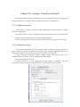
1
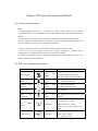
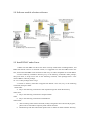
Inspur Storage System User
Manual
AS1000G6
Inspur
Dear users of Inspur server:
Sincerely thank you for selection of Inspur server!
This manual introduces the technical characteristics and the system installation, setup and
usage of Inspur storage system, and helps you to particularly understand and expediently use this
storage system.
Please deliver the package of our product to the waste recycling station for recycling, in favor
of pollution prevent and benefit the humankind.
This manual is the property of the Inspur Company.
This User Manual is not to be copied by any group or person in any manner without the
consent of Inspur Company. The Inspur Company. reserves the right of revise this manual
momentarily.
Any alteration about the content of this manual will not be noticed. We suggest that the
user shall read this manual before using Inspur storage system, so as to avoid any
mistake during operation.
Please forgive any insufficiency in details, point out and give directions for us
in time.
Please contact Inspur Company., if you have any questions or advice about this manual.
Inspur Company
Apr. 2014
“Inspur” is a registered trademark of the Inspur Company.
Windows is a registered trademark of Microsoft Corporation.
Other trade marks belong to other corresponding registered companies.
Statement
Please read the following statement before you use this server formally.
Only when you have read this statement hereinafter and agreed the following terms,
you can formally use this server. If you have any questions about the following terms,
please contact our supplier or us directly. If you have no questions about these terms
and start to use this server, it acquiesces that you have agreed the following terms.
1. We must call your attention that you must not alter any other parameters in the
main board BIOS of this server at any time, except for the parameters which we
promote that you can alter.
2. If there are any hardware problems when you use this server, or you wish to
upgrade the hardware, please feed back the detail hardware configuration of your
computer to our Customer Service. Don’t disassemble the server case or any hardware
components in the case by yourself.
3. Memory, CPU, CPU radiator, fan, disk tray and hard disk etc. of this storage system are of
special specification, please do not use them with equipment of any other type.
4. When you have any software problems during the application of this
server, we hope that you firstly contact the corresponding software supplier and then
he will contact us in favor of communication so as to solve your problem together,
especially the software problems about the database, the installation and running of
the network management software or other networking product.
5. Please read quick installation guide in this manual carefully before installing this storage
system. Inspur is engaged in constantly improving product function and performance, which may
cause part of functions different from description in this manual, but not impact usage, if you have
any doubt on usage, please contact our customer service center.
6. We must call your attention that in the application process, you should
pay attention to do necessary backup of your file.
7. This is a Grade A product, and this product may induce radio jamming. In this
case, users need to adopt feasible measures to the interference.
8. Please carefully read and comply with safety rules in this manual.
9. The copyrights of the markers and names of the software and hardware
product referred in this manual are the property of corresponding companies.
10. In the above statement, “us” indicates the Inspur Company. The Inspur
Company. holds the right of final explanation about the above statement.
Safety Rules
1. The power supply equipment in the system may generate high voltage and dangerous
electrical energy and thus cause personal injury. Please do not dismount the cover of the host or to
dismount and replace any component in the system by yourself, unless otherwise informed by
Inspur, only maintenance technicians trained by Inspur have the right to disassemble the cover of
the host, dismount and replace the internal components.
2. Please connect the equipment to appropriate power supply, and the power should be
supplied by external power supply which is indicated on the rated input label. To prevent your
equipment from damages caused by momentary spike or plunge of the voltage, please use relevant
voltage stabilizing equipment or uninterruptible power supply equipment.
3. If extended cables are needed, please use the three-core cables matched with correct
earthed plug, and check the ratings of the extended cables to make sure that the sum of rated
current of all products inserted into the extended cables do not exceed 80% of the limits of the
rated currents of the extended cables.
4. Please be sure to use the supplied power supply component, such as power lines, power
socket (if supplied with the equipment) etc. For the safety of equipment and the user, do not
replace randomly power cables or plugs.
5. To prevent electric shock dangers caused by leakage in the system, please make sure that
the power cables of the system and peripheral equipment are correctly connected to the earthed
power socket. Please connect the three-core power line plug to the three-core AC power socket
that is well earthed and easy to access, be sure to use the earthing pin of power lines and do not
use the patch plug or the earthing pin unplugged with cables. In case of the earthing conductors
not installed and it is uncertain whether there are appropriate earthing protections, please do not
operate or use the equipment. Contact and consult with the electrician.
6. To avoid short circuit of internal components and fire or electric shock hazards, please do
not fill any object into the open pores of the system.
7. Please place the system far away from the cooling plate and at the place with heat sources,
and be sure not to block the air vents.
8. Be sure not to scatter food or liquid in the system or on other components, and do not use
the product in humid and dusty environment.
9. The replacement of batteries with those of another model may cause explosion. When
replacement of batteries is required, please consult first the manufacturer and choose batteries of
the same or a similar model recommended by the manufacturer. Do not dismount, extrude and
pink the batteries or make the external connection point short circuit, and do not expose them in
the environment over 60°C. Never throw them into fire or water. Please do not try to open or
repair the batteries, and be sure to reasonably deal with the flat batteries and do not put the fl at
batteries, the circuit boards that may include the batteries and other components with other wastes.
For relevant battery recovery, please contact the local waste recovery and treatment mechanism.
Table of Content
Statement ......................................................................................................................................... 3
Chapter I Installation Preparations .................................................................................................... 8
1.1 Key terminology ................................................................................................................. 8
1.2 Necessary parts ................................................................................................................... 8
1.3 Hardware overview ............................................................................................................. 9
Chapter II Install HBA Card ........................................................................................................... 11
2.1 Key terminology ............................................................................................................... 11
2.2 Notes for installing HBA cards ......................................................................................... 11
2.3 Install HBA card................................................................................................................ 11
Chapter III Configure Switches ...................................................................................................... 12
Chapter IV Quick Installation Guide .............................................................................................. 13
4.1 Cabinet preparation ........................................................................................................... 13
4.2 Storage system guide rail suite .......................................................................................... 14
4.3 Install guide rail to cabinet ................................................................................................ 14
4.4 Install the equipment into cabinet ..................................................................................... 16
Chapter V Connect Controller and Host ......................................................................................... 18
5.1 Key terminology ............................................................................................................... 18
5.2 Host connection notes ....................................................................................................... 18
5.3 Steps to connect host ......................................................................................................... 19
5.4 Host channel connection topology .................................................................................... 19
5.4.1 Direct connection topology .................................................................................... 19
5.4.2 Switch connection topology ................................................................................... 20
5.4.3 Mixed connection topology.................................................................................... 20
5.5 Management method topology .......................................................................................... 21
5.5.1 In-band management .............................................................................................. 21
5.5.2 Out-of-band management....................................................................................... 22
Chapter VI Connect Extension Cabinet .......................................................................................... 23
6.1 Key terminology ............................................................................................................... 23
6.2 Connection notes ............................................................................................................... 23
6.2.1 Disk channels ......................................................................................................... 23
6.2.2 Extension cabinet connection notes ....................................................................... 23
6.3 Extension cabinet connection steps ................................................................................... 24
6.4 Disk array extension illustration ....................................................................................... 24
Chapter VII Connect Power Supply ................................................................................................ 27
7.1 Power line connection notes.............................................................................................. 27
7.2 Power line connection steps .............................................................................................. 27
Chapter VIII System Power-on and Check ..................................................................................... 28
8.1 System power-on steps ...................................................................................................... 28
8.2 Disk array indicator description ........................................................................................ 28
8.3 Part repair indicator ........................................................................................................... 29
Chapter IX Install Storage Management Software ......................................................................... 30
9.1 Key terminology ............................................................................................................... 30
9.2 Installation introduction .................................................................................................... 30
9.3 Operation system special introduction .............................................................................. 30
9.4 Installation environment requirement ............................................................................... 31
9.5 Disk space requirement ..................................................................................................... 32
9.6 Software installation steps................................................................................................. 32
9.7 SANtricity management software module introduction .................................................... 32
9.8 Software module selection reference ................................................................................ 33
9.9 Install RDAC under Linux ................................................................................................ 33
Chapter X Configure HBA Cards ................................................................................................... 34
10.1 EMULEX HBA card configuration................................................................................. 34
10.1.1 For SUSE Linux Enterprise Server 9 operation system ....................................... 34
10.1.2 For solaris operation system................................................................................. 34
10.1.3 For Windows server 2003 and Windows server 2008 .......................................... 34
10.2 Qlogic HBA (BIOS Configuration)................................................................................. 35
10.2.1 For Linux, windows server 2003/2008 operation systems ................................... 35
Chapter XI Start Management Software ......................................................................................... 36
11.1 Management software startup ......................................................................................... 36
11.2 Enterprise Management Window (EMW) and Array Management Window (AMW) .... 36
Chapter XII Add a Storage Array .................................................................................................... 37
Chapter XIII Name the Storage Array ............................................................................................ 39
13.1 Naming notes .................................................................................................................. 39
13.2 Naming steps ................................................................................................................... 39
Chapter XIV Troubleshooting ......................................................................................................... 40
Chapter XV Configure Controllers Manually ................................................................................. 41
15.1 Configuration notes ......................................................................................................... 41
15.2 Configuration steps ......................................................................................................... 41
Chapter XVI Set a Password ........................................................................................................... 43
16.1 Password setting notes .................................................................................................... 43
16.2 Password setting steps ..................................................................................................... 43
Chapter XVII Configure Email and SNMP Alarm ......................................................................... 44
17.1 Configuration notes ......................................................................................................... 44
17.2 Alert notification configuration steps .............................................................................. 44
17.3 Mail server tab ................................................................................................................ 44
17.4 Email tab ......................................................................................................................... 44
17.5 SNMP tab ........................................................................................................................ 45
Chapter XVIII Cache Setting .......................................................................................................... 46
18.1 Cache setting notes.......................................................................................................... 46
18.2 Modify cache setting ....................................................................................................... 46
18.3 Modify volume cache setting .......................................................................................... 46
Chapter XIX Add a Host ................................................................................................................. 47
19.1 Key terminology ............................................................................................................. 47
19.2 Adding host notes ............................................................................................................ 47
19.3 Define a host group ......................................................................................................... 47
19.4 Storage partition usage notes .......................................................................................... 47
19.5 Adding a host steps ......................................................................................................... 49
Chapter XX Configure Storage System .......................................................................................... 50
20.1 Key terminology ............................................................................................................. 50
20.3 Capacity allocating notes ................................................................................................ 50
20.3 Volume group and volume creating notes ....................................................................... 51
20.4 Host to volume mapping and storage partition notes ...................................................... 51
20.5 Hot spare disk usage notes .............................................................................................. 51
20.6 Storage configuration steps ............................................................................................. 51
Chapter I Installation Preparations
This chapter mainly describes preparations for installing AS1000G6 storage system.
1.1 Key terminology
Controller main cabinet
Controller main cabinet contains one or two controllers, power modules and fan modules etc.,
controller main cabinet provides interfaces for storage disk arrays and the host, and 12 hard disks
could be inserted into controller main cabinet.
Extension cabinet
Hard disks could be installed on extension cabinet, except controller, it contains environment
services monitor (ESM), power module and fan module etc. Extension cabinet is usually
connected to the back of controller main cabinet, and could be connected to other extension
cabinets, so as to meet expansion of disk array volume.
SFP
SFP is a kind of equipment communicating with fiber optical equipment, SFP could be used
on HBA cards and controllers.
1.2 Necessary parts
Hardware
Cabinet
Make sure cabinet complies with AS1000G6 specification, and
power supply could provide sufficient power.
Guide rail
support and
screws
Used for installation of storage AS1000G6.
Cables
Power lines
Power lines installed together with storage could be used to
connect an external power supply, if your cabinet is
equipped with special power lines, these could be replaced.
Optical fiber
lines
Use optical fiber lines to connect storage arrays and the host or
optical switches.
Ethernet cables
Used to connect storage arrays to carry out out-of-band
management.
Other tools
Screwdrivers
One slotted screwdriver and one Phillips screwdriver.
Antistatic
equipment
To avoid static damages.
Label paper
Used to mark positions.
1.3 Hardware overview
Front view of AS1000G6(2U12) is as shown in the following Figure 1-1.
Figure 1-1 Front View of AS1000G6(2U12)
Front view of AS1000G6(2U24) is as shown in the following Figure 1-2.
Figure 1-2 Front View of AS1000G6(2U24)
Hardware sequence, row one (1-4). Row two (5-8), row three (9-12).
Number
Name
Number
Name
1
Backup power indicator
6
Disk driver module
2
Power indicator
7
Maintainable
3
Temperature alarm indicator
8
Disk fault indicator
4
Service operation indicator
9
Disk power indicator
5
Position indicator
Rear view of AS1000G6 is as shown in the following Figure 1-3:
Figure 1-3 Rear
R View off AS1000G6
N
Num
ber
Nam
me
Num
mber
Nam
me
1
A conntroller moduule
12
2
Fiber channel
c
operaation indicato
or
2
Sevenn-segment diggital display
13
3
Extenssion fault inddicator
3
USB Interface
14
4
Extenssion operationn indicator
4
Netwoork operationn indicator
15
5
SAS extension
e
inteerface
5
Netwoork rate indiccator
16
6
Powerr supply-fan m
module
6
Netwoork interface 2
17
7
Backuup power indiicator
7
Fiber channel 1
18
8
DC poower indicatoor
8
Fiber channel connnection indicaator
19
9
Permitt maintenancee indicator
9
Fiber channel operration indicattor
20
0
Powerr fan operatioon indicator
10
Fiber channel 2
21
AC poower indicatoor
11
Fiber channel connnection indicaator
22
2
Powerr connector
Chapter II Install HBA Card
2.1 Key terminology
HBA card (host bus adapter)
Host bus adapter, physical card installed on the host, providing data IO transmission between
the host and storage controller.
Host port of HBA card
Physical and electrical interface in the host for HBA card to connect storage, most HBA cards
have one or two host ports. Each HBA card has a unique WWID number, and host port of each
HBA card has a unique WWID number.
2.2 Notes for installing HBA cards
Host channel of AS1000G6 is FC, and FC HBA card needs to be used on the host, while FC
switch needs to be used on switch, and the speed shall match either.
In order to provide the maximum hardware redundancy, 2 HBA cards need to be installed on
one host, and dual HAB card provides 2 host ports, rather than redundancy feature.
In order to achieve the maximum performance, it is better to use 8Gb storage host
channel with an 8Gb HBA card, if a 4Gb HBA card is used, data transmission rate will be kept at
4Gb.
When host operation system is VMware, mixed connection will not be supported in one
partition.
Windows operation system does not support mixed connection in one partition, when a host
uses multiple partitions to connect the same storage array, no repeated lun number shall be used.
Mixed connection from a host to a storage array is not supported by other operation systems.
2.3 Install HBA card
1. Make sure the HAB card in use is compatible with storage.
2. Install HBA cards according to documents provided by manufacturer.
3. Restart the host.
4. During self-checking of the host, pay attention to prompt messages about entering HBA
card BIOS, enter HBA card BIOS according to these messages.
5. Record the following information: Host name, HBA card on the host, host port WWID on
each HBA card.
Chapter III Configure Switches
1. Make sure the switch in use is compatible with this storage array.
2. Install the switch according to documents provided by switch manufacturer.
3. Visit website of optical switch manufacturer, obtain the latest Firmware and management
software, and update optical switch Firmware, you may need to shut down the switch to restart.
4. If a Brocade or Cisco optical switch is used, it is required to use configuration
management of the switcher to open IOD (in-Order Delivery) option.
Chapter IV Quick Installation Guide
This part mainly introduces quick installation of the equipment, according to the following
description, you could complete installation of the equipment in the shortest time, in the
safest way.
Note
Threaten brought by static electricity – Static electricity is a fatal threaten to electronic
equipment, for static electricity may puncture some electronic parts, causing failure of the whole
equipment, and bringing along huge losses unconsciously. So, during operation on equipment,
make sure to carry out electrostatic protection, which will not be noted in the following sections.
4.1 Cabinet preparation
Cabinet leveling: Cabinet must be placed firmly, adjust four legs at the bottom, make the cabinet
be placed on the ground firmly. Meanwhile, dismantle cabinet door and side panel
for guide rail installation.
Cabinet grounding: In order to avoid electric shock risk, it is required to install an earthing device
inside the cabinet. If power line of this equipment is inserted into power socket as
part of the cabinet, proper earthing must be provided for the cabinet. If power line
of storage system is inserted into power socket on the wall, earthing device inside
power socket only provides earthing for this equipment, it is required to provide
proper earthing protection for the cabinet as well as other equipment inside it. It is
suggested that you shall use the cabinet specially designed for Inspur storage system.
If you’re using an Inspur storage cabinet, and all parts inside the cabinet are
grounded, Please do not change any of earthing connections inside the cabinet.
Temperature: If storage equipment is installed inside the cabinet, operating and working
temperature of storage system shall not be lower than 5℃, nor higher than 35
℃.
Ventilation: Cabinet used by storage equipment shall provide sufficient wind flow for front and
rear parts of the system, and shall guarantee a 4100Btu heat discharge per
hour, while above 1m space shall also be kept in front and rear.
4.2 Storage system
s
guiide rail suuite
A
Articles
contaained in guide rail suite foor this equipm
ment are as shhown in Tablee 4-1.
Table 4-1
4 Guide Raail Suite
Description
Illustratioon
L type guide rail (one piecee on left and right)
r
z
This guidde rail adoptss the design of
o rear-hang, fflexible probe
and free of
o nuts, greatly simplifyinng installationn process.
z
This guidde rail appliies to installation of 2U,, 3U and 4U
U
equipmennt, and can reeach a 65kg bearing.
F
Front
positionn columns (2 for
f each, 4 inn all)
z
Usually attached
a
to the front rail.
z
Fix the position colum
mn on front rail,
r
install it into the angle
rail hole, to undertake gravity.
R
Round
head sccrews (M5×6
6, 2 screws for each, 4 screews in all)
z
Usually 1 screw is attaached to fronnt and rear rail respectively
y.
z
During usage,
u
fix gu
uide rail onto angle rail, to fix and
d
undertakee gravity.
C
Crown
screwss (M5×16, 1 screws
s
for eacch, 2 screws iin all)
z
Usually attached
a
to the front rail.
z
During usage,
u
fix gu
uide rail onto angle rail, to fix and
d
undertakee gravity.
4.3 Install guuide rail too cabinet
1. Lenngth of front and rear raill could extend
d freely whenn pulled, in oorder to guaraantee
guide rail bearing, a cerrtain friction is required during
d
extension, otherwisse, both frontt and
t contrary, if too tight, front and raiil rails will not be
rear rails wiill become tooo loose; on the
able to exteend, it is reqquired to looosen four tu
urnbuckle scrrews as show
wn in Figuree 4-1
according too situation.
Tuurnbuckle screew
Figure 4-1
4
2. Extend front and rear guide rails, to make its length equivalent to front and rear
distance of cabinet angle rail.
3. Confirm installation position of the equipment, generally, a height scale is marked
on cabinet angle rail, and introduction will be given in below taking 32U position installation
as an example.
4. On rear guide rail, there’re two connectors, align the lower connector with the
second hole above the starting point of 32U scale on angle rail, the upper connector with the
second hole above the starting point of 33U scale, insert the connector through the hole, and
then press it down, to connect it to angle rail, now L-shaped part of guide rail shall be
leveled with the starting point of 32U scale, and rear rail fixing holes shall display in the
center of the third hole above the starting point of 32U, as shown in Figure 4-2.
Rear rail fixing hole
Keep level
Figure 4-2
5. Adopt guide rail standard configuration of M5×6 round head screws, screw in rear
rail fixing holes, to fix guide rail.
6. Adjust fixing positions of two fixing columns of front guide rail as required, so as to
leave corresponding positions for front fixing holes of the equipment, place guide rail to a
horizontal position, align lower edge with 32U starting point, extend fixing columns into
angle rail fixing holes, and fix them with round head M5×6 screws, as shown in Figure
4-3, while fixing positions of round head M5×6 screws are also required to be ascertained
according to corresponding positions of front fixing holes of the equipment, so as to avoid.
Round head screw
Fixing column
Figure 4-3
7. Fasten four fixing screws between front and rear rails.
8. Install guide rail on the other side of the cabinet, according to the above steps, be
noted that guide rails on both sides shall be leveled, that is on the same height.
4.4 Install the equipment into cabinet
Note:
z
For storage equipment is heavy, in order to guarantee safety, when installing storage
equipment into the cabinet, at least 4 persons are needed to move the storage system.
1. Lift the storage equipment, make it close to guide rail, and align lower angles on both
sides in front of the storage system, with angles of L-shaped rails on left and right sides.
2. To keep the storage system leveled, place the front of storage system on L-shaped guide
rail (now persons in the front shall support it to guarantee safety), push it into the
cabinet steadily, after entering about 1/3, the number of persons could be reduced to two,
finally, push the equipment into the cabinet completely, as shown in Figure 4-4.
Figure 4-4
3. Adopt M5-16 crown screws, and fix storage system into the cabinet, via fixing holes on
ears in front of the chassis.
4. Fix ears on both left and right panels onto both sides in front of the chassis.
5. Install hard disks according to the sequence of from left to right, and from up to down.
Chapteer V Connnect Con
ntroller annd Host
5.1 Key term
minology
access volume
v
usedd to manage communicattion between the host annd storage. acccess
A special volume,
voluume is only ussed for in-bannd managemeent.
Switch stru
ucture and diirect connecttion
Using an opptical switch to connect diisk array and
d the host is called
c
a switcch structure, while
w
direcct connectionn means to coonnect withouut switch, serv
ver or disk arrray.
In-band maanagement
host uses ddata transmission
A storage management
m
method, unnder which management
m
channnel to transfeer managemeent commands and informaation.
Out-of-ban
nd managemeent
Use Etherneet network to connect storaage, and man
nage storage array.
a
5.2 Host connection nootes
Host chann
nel
Each controller has 4 or 8 FC host chaannels.
The followinng Figure 5-11 is 8 host chaannels of each AS1000G66 controller.
Host Channel
Host Interfaace Card (HIC
C)
Figure 5-1 Host
H Channels and Host In
nterface Cardd Illustration
Notee:
1. Do not dismantle
d
or take out anyy part of SFP
P on host channnel, you maay expose to laser
radiaation.
2. Static discharge
d
maay damage seensitive com
mponents, in order to avooid damaging
g the
equiipment, please adopt propeer anti-static protective
p
meeasures whilee handling any part.
Host interfaace cards
AS1000G6 host
h interfacee cards (HIC)) are as show
wn in the abovve Figure 5-1, FC HIC carrds (4
8Gbb FC channelss), if use a 4G
Gb FC HBA card to conneect an 8Gb FC
F HIC card, data transmission
rate will be at 4Gb/s.
5.3 Steps to connect host
1. Confirm there’s an SFP module inserted in host channel, and plug off black plastic plug on
SFP.
2. As for FC host channel, insert one end of fiber-optic cable into SFP interface of host
channel.
3. Insert the other end of the cable into corresponding host FC HBA card/network card or
switch, and guarantee the rate matches with protocol.
4. It is suggested to label both ends of the cable, which is very important for you when
disconnect the cable and carry out operation on controller.
Suggested label content includes: Hostname and HBA card ports, controller ID (i.e. controller A),
host channel ID (i.e. host channel 1).
Label writing example: i.e. a cable is used to connect No. 1 port in No. 1 HBA card of a host
named Heng with No. 1 host channel of controller A, and label could be abbreviated according to
the following: Heng-HBA1/P1,CtA-Hch1
5. Repeat these steps to connect all host channels to be used.
5.4 Host channel connection topology
5.4.1 Direct connection topology
One host is directly connected to a dual-controller disk array.
Figure 5-2 Direct Connection Topology
5.4.2 Switch connection topology
Two hosts are connected to dual-controller storage disk array via switch.
Figure 5-3 Switch Connection Topology
5.4.3 Mixed connection topology
3 hosts are connected to a dual-controller storage array via 2 switches.
Figure 5-4 Mixed Connection Topology
Note: Host channel with the highest number is reserved for remote volume mirroring, to enable
this function, do not use the host channel with the highest number.
5.5 Management method topology
5.5.1 In-band management
Figure 5-5 In-band Management
In-band management does not need management port connection cable of the controller, but
to install host-agent software, and map access volume to the host, so that the host could
communicate with storage via access volume. This method occupies a part of data bandwidth.
5.5.2 Out-of-band management
Figure 5-6 Out-of-band Management
Out-of-band management needs not to use access volume, but to connect both controllers to
management network, and default ip addresses of two controllers are 192.168.128.101 and
192.168.128.102.
Chapteer VI Connnect Ex
xtension Cabinet
C
6.1 Key term
minology
Disk channels
Channels ussed to transmiit data betweeen controller and extension cabinet of ddisk array.
ESM(enviroonmental serrvices monittor)
Environmennt services monitor, a module monitoring
m
p
part
status inside exten
nsion
r
of conneection, transm
mitting data between
b
extennsion cabinett and
cabinet, which also plays a role
diskk array controller, and eachh extension caabinet has two ESM moduules.
6.2 Connection notes
6.2.1 Disk channnels
Each controoller has 1 SAS disk exteension chann
nel, as shownn in the folloowing Figuree 6-1
AS1000G6 Disk Extension Chhannel Illustrration.
Disk
D Extension Channel
Figure 6-1 AS1000G
G6 Disk Extension Channeel Illustrationn
6.2.2 Extensionn cabinet coonnection nootes
Extension caabinet conneccted to AS10000G6 (each ESM
E
modulee) contains tw
wo input portss and
one output port. The
T followingg Figure 6-2 is
i rear view of
o extension cabinet.
c
Inpuut Port
Output Port
P
Figure 6-2 Rear
R View of Extension
E
Caabinet
6.3 Extension cabinet connection steps
2. Insert one end of an SAS cable into disk extension channel port of disk array controller,
and insert the other end into corresponding ESM disk channel I/O port.
3. To carry out maintenance on controller via disconnecting SAS cable, label is very
important, it is suggested to adopt the following method to add a label to both ends of
fiber-optic cable: Controller ID (i.e. controller A), disk channel ID and port ID (i.e. drive
channel 1, port 4), ESM ID (i.e. ESM A), extension cabinet ID, label abbreviation such as:
Connect No. 2 port of No. 1 disk channel of controller A with output port 1B of left ESM (A)
in the first extension cabinet of No. 2 port of No. 1 disk channel, and the label is:
CtA-Dch1/P2,Dm1-ESM_A(left), 1B.
4. Repeat the above steps to connect disk channels of each controller in use.
6.4 Disk array extension illustration
Connect one extension cabinet
Figure 6-3 Connect 1 Extension Cabinet
Connect 2 extension cabinets
Figure 6-4 Connect 2 Extension Cabinets
Connect multiple extension cabinets
Figure 6-5 Connect Multiple Extension Cabinets
Chapter VII Connect Power Supply
7.1 Power line connection notes
1. For each power supply on disk array, it is recommended to use different power inputs
inside the cabinet, and independent two power inputs could guarantee power redundancy.
2. Power line equipped with disk array shall meet standards required by safety
regulations of the nation, and could connect sockets or UPS directly.
7.2 Power line connection steps
1. Guarantee all power switches on disk array and all power switches of extension
cabinet connected to it are turned off.
2. Connect power line from the cabinet to disk array or sockets on extension cabinet
power module.
3. Connect main power line of the cabinet to an external power supply.
Chapter VIII System Power-on and Check
8.1 System power-on steps
Note:
1. Before enabling disk array, it is required to connect power supply of all connected
extension cabinets, so as to guarantee the controller could recognize all connected extension
cabinets.
2. Wait at least 30 seconds to power on the main cabinet after enabling extension cabinet.
3. When storage array (main cabinet or extension cabinet) is connected to power supply, front
and rear indicators of storage array will flash intermittently.
1. Turn on all power switches on all extension cabinets connected to disk array.
2. Turn on two power switches of the main cabinet, according to different system
configurations, a complete system startup may need several minutes.
3. Check front and rear indicators of the main cabinet and extension cabinet, if there’s any
yellow indicator, record its position.
8.2 Disk array indicator description
Indicator
Signal
Position
Function
Chassis panel
On - The module is electrified
Off - The module is not electrified
Power Supply
Left
panel
front
Temperature
alarm
Left
panel
front
On - Temperature over high
Off - Temperature normal
Backup
indicator
Left
panel
front
On - Power backup status
Off - Power balanced status
Fault indicator
Left
panel
front
Disk
array
positioning
Left
panel
front
Host
speed
power
channel
Cache activity
On - Part fault
On - Help position part or store array
location
Controller
Host channel speed indicator
Left indicator on - 2Gb/s
Right indicator on - 4Gb/s
Both left and right indicators on 8Gb/s
Controller
Displays cache activities
Flash - Data in cache
Off - No data in cache.
Box
symbol/diagnosis
display
Ethernet
Controller
Displays box symbol or diagnosis
code
Controller
Left indicator symbol connection rate
Right indicator symbol connection
status
Left indicator on - 1000MB/s
Left indicator off - 100MB/s or
10MB/s
Right indicator on - Connection
established
Right indicator off - No connection is
established
Flash activity
Diagnosis code and description
L0
Not matched controller type
L1
Missed interconnection module of internal battery
L2
Permanent memory error
L3
Permanent hardware error
L4
Permanent data protection error
L5
Automatic code synchronization (ACS) failure
L6
Not supported host interface cards
L7
Subtype symbol not set or not matched
L8
Memory setting error
L9
Connection speed not matched
LB
Host card configuration error
LC
Memory setting error
LD
Memory mixed DIMM
LE
Memory problem
LF
Restricted SYMbol lock
LH
Controller firmware not matched
8.3 Part repair indicator
There’s a green indicator permitting part repair in each power fan module, controller module
and internal battery interconnection module, instructs operators to dismantle parts in a safe way
(dismantling parts before part repair indicator is on may cause data loss).
Part repair indicator may light up or off automatically with situation change, under most
circumstances, permit repair indicator only lights up when a certain part fails and fault indicator is
on, if fault indicator is on but permit repair indicator is off, it may need to repair other parts first,
please check storage management software to decide measures to be adopted.
Chapter IX Install Storage Management Software
9.1 Key terminology
RDAC(redundant dual active controller multipath driver)
In order to configure IO transmission driver of disk array management data of redundancy
controller. If a certain part connecting storage array fails, causing communication between the host
and controller lost, this driver will relocate all IO paths automatically, and switch to another
controller of storage array if necessary.
Host
Connects to storage array, and accesses volume on storage array via host ports on HBA cards.
Management workstation
Runs computer of storage management software, used to add, monitor and manage storage
arrays on network.
9.2 Installation introduction
This introduction is used to install installation wizard of SANtricity management software,
and independent installation software packages of various operation systems are provided in CD.
For windows 2003, 2008 operation systems, Linux and solaris operation systems, storage
management software supports to use storage array as a guide device (excluding IA64 architecture
Itanium machine).
9.3 Operation system special introduction
Solaris:
When the number of volumes is no more than 32, solaris operation system supports RDAC
path redundancy software, when more than 32 data volumes, a Multiplexed I/O(MPxIO) could be
used. Solaris operation system supports SUN clustering software.
(RDAC only supports solaris 9)
Windows XP and Windows Vista:
These two operation systems only support SANtricity client, rather than other software
packages such as RDAC multipath software, SANtricity installed on these two systems could only
be used as a storage management workstation, and does not support VDS, VSS of Microsoft, nor
SMI of SINA.
Windows server 2003 and Windows server 2008:
When RDAC driver is not installed, an error message prompts after installation is done, indicating
if there’re several alarming notices after installation, it is suggested to view installation log to
understand detailed situation, and installation log includes win32 abnormal warnings, which is
normal, and the installation process is successful.
Linux Red Hed 5 Client and SUSE desktop 10:
Only SANtricity client software package is supported, while other software packages such as
RDAC multipath software are not supported, and SANtricity installed on these two systems could
only be used as a storage management workstation.
Red Hat Enterprise Linux and SUSE Linux Enterprise Server:
These two operation systems support RDAC multipath software, as well as SteelEye
LifeKeeper, Novell Open Enterprise Server (OES) and Native Red Hat Clustering software.
(RHLE 4 does not support SteelEye LifeKeeper under IA64 architecture)
9.4 Installation environment requirement
Operation System
System Edition
Windows XP
x86-based system (32-bit and 64-bit)
Pentium or greater CPU or equivalent (233 MHz minimum)
Professional Service Pack 2 (SP2) or later
Note: Only storage management workstation is supported.
Windows server
2003
x86-based system (IA32, Intel Xeon, and 32-bit or 64-bit AMD
Opteron)
IA64
Standard Edition, Enterprise Edition, SP 2
SP 1 or x64 Edition (64-bit x86-based system only)
Windows Vista
x86-based system (32-bit and 64-bit)
Pentium or greater CPU or equivalent (800 MHz minimum)
Business Edition or higher
Note: Only storage management workstation is supported.
Windows server
2008
x86-based system (IA32, Intel Xeon, and 32-bit or 64-bit AMD
Opteron)
IA64
Standard (Server Core) Edition, Enterprise (Server Core)
Edition,
Web Edition
Linux
x86 (32-bit and 64-bit)
IA64
PowerPC processor (IBM only)
Red Hat Enterprise Linux 4.0 Update 6
Red Hat Enterprise Linux 5.0 Update 1
SUSE Linux Enterprise Server 9.0 UP 4, 10 SP 1
Red Hat 5.0 Client (only storage management workstation)
SUSE Linux Enterprise Desktop 10 (only storage
management workstation)
Solaris
SPARC-based system
x86-based system (Intel Xeon, and 32-bit or 64-bit AMD
Opteron)
Solaris 8, Solaris 9 (SPARC only)
Solaris 10
9.5 Disk space requirement
Operation System
Spare
Space
Windows XP
255MB
Windows Server 2003
291MB
Windows Vista
291MB
Windows Server 2008
291MB
Linux
390MB
Solaris
540MB
Other Requirements
(Min. memory is 512MB)
9.6 Software installation steps
1. Insert SANtricity management software CD into CD-ROM.
2. Open installation folder.
3. Start installation program,
Windows – Double click executable files, i.e. SMIA-W32.exe.
Linux – Key in a proper command in command prompt to start installation program, i.e. sh
SMIA-LINUX.bin.
4、 Installation wizard appears, install according to wizard.
9.7 SANtricity management software module introduction
Client – This software contains graphic user interface used to manage storage array, as well as
optional monitoring program, used to send an alarm message when a serious problem occurs in
storage array.
Practical program – This software contains various practical programs, which could be used to
enable operation system to recognize volumes created on storage array and view specific
operation system device name of each volume.
Agent – This software enables management workstation to communicate via data IO path of the
host and controller in storage array.
Fault switch driver – This software contains multipath driver, used to manage IO data path of
controller in storage array. If any problem occurs in path or any controller fails, this driver will
redirect IO requests from the host automatically, and send them to another controller in storage
array.
Java access bridge (JAB) – It contains bridge software, making customer application based
on windows technology could access mutually, and operate interactively.
9.8 Software module selection reference
Figure 9-1
9.9 Install RDAC under Linux
1. Make sure that HBA card driver has been correctly loaded before installing RDAC, and
HBA card shall be a driver of non-fault switch, it is suggested to use the same HBA card in one
host, and confirm that HBA cards connected to disk array are within compatible list of AS1000G6.
2. Enter SANtricity installation directory, key in the following commands under prompts,
then press Enter, to unzip source file. In the following command, <rdac-package-name> is the
name of RDAC software package.
tar –zxvf <rdac-package-name>.tar.gz
3. Switch to directory linuxrdac unzipped from RDAC source file, key in the following
commands, then press Enter.
cd linuxrdac
4. Key in the following command to clean repeated target files under the directory.
make clean
5. Key in the following command to compile module.
make
6. Key in the following command to install RDAC.
make install
7. After executing make install command, modify configuration file of boot-load program,
please refer to information output by make install command.
8. Detailed steps and other information please refer to readme.txt under linuxrdac directory.
Chapter X Configure HBA Cards
10.1 EMULEX HBA card configuration
10.1.1 For SUSE Linux Enterprise Server 9 operation system
1. Use Emulex HBAnyware tool to change the following parameter values:
lpfc_nodev_tmo = 60
2. Restart the host.
10.1.2 For solaris operation system
1. Modify parameter values in /kernel/drv/lpfc.conf file.
Automap = value
Value
Binding Types
0
Only scan binding
1
WWNN(world-wide node name)binding
2
WWPN binding
3
DID binding
No-device-delay = 0
Network-on = 0
Linkdown-tmo = 60
Nodev-tmo = 60
2. Restart the host.
10.1.3 For Windows server 2003 and Windows server 2008
Note: Registry editor is an advanced tool, and any error in setting may cause serious
problems, please make sure to backup registry configuration files before modification.
1. Click Start-->Run.
2. Enter regedit, click Ok, to edit registry.
3. Edit values according to the following table.
Registry Items
Win2003 Server and Win2008 Server Values
HKEY_LOCAL_MACHINE >> System >> CurrentControlSet >>Services >> elxstor >> Parameters >> Device
(under theDriverParameter variable)
NOTE – DriverParameter is of the type REG_SZ. Add these parameters to the
DriverParameter string. Do not create a separate key for each of the parameters.
LinkTimeOut
60
NodeTimeOut
60
HKEY_LOCAL_MACHINE >> System >> CurrentControlSet >>Services >> md3dsm or mppdsm >> Parameters
SynchTimeOut (REG_DWORD)
x78
DisableLunRebalance
[value_for_cluster] (REG_DWORD)
NOTE – Change this value only if you are using the
0x03
Microsoft Cluster Service.
HKEY_LOCAL_MACHINE >> System >> CurrentControlSet >>Services >> Disk
TimeOutValue (REG_DWORD)
X78
4. Restart the host.
10.2 Qlogic HBA (BIOS Configuration)
10.2.1 For Linux, windows server 2003/2008 operation systems
1. Restart the host.
2. When the host is started, view prompts, and press ctrl+Q to enter HBA card BIOS.
3. Select an HBA card to view its configuration.
4. Select configuration setting, and set according to the following values.
Configuration Options
Linux OS
Windows Server 2003
and Windows Server
2008
Host Adapter Settings
LoopResetDelay
8
AdapterHardLoopID
(recommended
only
for arbitrated loop topology)
Enabled
HardLoopID (recommended only for
arbitrated loop topology)
Any unique number. Typically set to
20, 21, or 22.
Advance Adapter Settings
ExecutionThrottle
256
LUNsperTarget
NOTE – 0 activates maximum LUN
support.
0
EnableTargetReset
Yes
LoginRetryCount
30
PortDownRetryCount
35
LinkDownTimeout
60
5. Save settings.
6. Select another HBA, and repeat step 3-5.
7. Restart the host.
70
Chapter XI Start Management Software
11.1 Management software startup
1. Start SANtricity storage management software.
Under windows system: Select Start>>Program>> SANtricity Storage Manager Client
Under UNIX operation system: Key in SMclient after command prompt and then press Enter.
2. Software runs and prompts an enterprise management window, select storage system to
manage and double click, an array management window displays.
11.2 Enterprise Management Window (EMW) and Array Management
Window (AMW)
EMW and AMW are two basic windows used for centralized management on storage array.
When SANtricity management software is running, enterprise management window (EMW) will
display first, which is used for centralized management on storage system in the enterprise, double
click disk array in EMW, management software will display AMW user interface.
User Interface
Enterprise
Window (EMW)
Description
Management
Array Management Window
Setup Column
AMW)
(EMW
Main window appears when SANtricity management software
is started for the first time.
User could view all storage arrays in management field.
Used to add and delete storage arrays, set alarm notification
(email and SNMP) as well as execute other advanced
configuration.
Provides statuses of all storage arrays.
User could configure storage arrays via starting AMW
management.
Provides functions required to configure and maintain
individual storage array, as well as fault detection.
User could start AMW from EMW to carry out management
on individual storage array.
Multiple AMWs (each storage array occupies a window) could
be displayed synchronously.
and
Setup column provides quick entries for certain options, which
are different according to different windows (EMW or AMW).
Setup page under EMW window
Figure 11-1
Setup page under AMW window
Figure 11-2
Chapter XII Add a Storage Array
1. Select Tools>>Automatic Discovery from enterprise management window.
2. Click Ok to start auto search, this operation will search all storage arrays in local
LAN, which may need several minutes or longer time. If no storage array is found, the reason may
be network setting of storage array does not belong to local LAN, in this case, it is required to add
a storage array manually.
3. If not storage array is found via auto search, select Add New Storage Array-Manual in
enterprise management window, to add a storage array manually, the interface is as shown in the
following figure,
Figure 12-1
4. Select a corresponding management, if it is an out-of-band management, input ip addresses
of two controllers (in IPv4 network, default management addresses of controller A and B are
192.168.128.101 and 192.168.128.102), if it is a in-band management, input hostname or ip
address of the agent host, click add, the added storage array will display in EMW window.
Chapter XIII Name the Storage Array
13.1 Naming notes
1. Disk array name in storage array software could be composed of letters, digits and special
characters “_”, “-“ or “#”, except these, no other special characters are allowed.
2. When name a storage array, prefix “Storage Array” will be added before the name
automatically.
3. When a storage array is first detected automatically or added manually, the default name of
this storage array is “unnamed”.
13.2 Naming steps
1. Select an unnamed storage array and click locate, confirm its physical location via
positioning indicator;
2. Select Setup interface in enterprise management window, click name/rename storage
arrays.
3. Repeat the above steps for each unnamed storage array.
Chapter XIV Troubleshooting
If there’s any yellow indicator noticed during system power-on and checking, there will be a
corresponding indication in enterprise management window (EMW) which stores management
software.
1. In enterprise management window which stores management software, user could see
running status of arrays: Optional indicates normal running, without any problem, needs
attention indicates a problem, which needs attention.
2. Select a storage array with needs attention status, click Ok, to start corresponding array
management window (AMW).
3. Click Recover Guru, and solve existing problems according to hints.
4. Click re-check in Recover Guru, and verify whether problems have been solved.
Chapter XV Configure Controllers Manually
This chapter introduces how to use SANtticity storage management software to configure and
change IP addresses of controllers under the condition that there’s no DHCP server.
15.1 Configuration notes
1. Please refer to content in Chapter V Select Management to decide whether to change
controller configuration.
2. Use Ethernet port 1 on each controller for storage management, and reserve Ethernet port
2.
3. Ethernet port 1 and Ethernet port 2 shall be in different subnets.
4. Gateway configuration could only be carried out on one Ethernet port on each controller.
15.2 Configuration steps
1. Use in-band management or private network (laptop connects to storage controller via
switch or direct connection) to initialize to find storage arrays (default management addresses of
controller A and B in IPv4 network are 192.168.128.101 and 192.168.128.102).
2. Open enterprise management window (EMW), double click storage arrays to be
configured in Device column, an array management window displays.
3. Click Logical/Physical column.
4. Select controller A in array management window (AMW) to highlight, and select
controller>>configure>>Ethernet management ports , as shown in the following figure,
Figure 15-1
5. Select controller A, port 1 in dropdown list of Ethernet port, and select auto-negotiate in
dropdown list of speed and duplex mode (make sure that the switch in use is also set to
auto-negotiate).
6. Select IPv4 or IPv6 according to network type, and set proper network parameters.
7. Select controller B and repeat step 406 to set network parameters for controller B.
Chapter XVI Set a Password
This chapter introduces how to set a password in SANtticity storage management software,
as well as other notices.
16.1 Password setting notes
1. In order to enhance protection function, please set a long password containing at least 15
letters, digits and characters. Max. password length could reach 30 characters.
2. Password is case sensitive.
3. Only at first attempt to change configuration (i.e. create a volume) or first execute a
destructive operation (i.e. delete a volume), a password is required to be entered.
4. No password is required to view operation.
5. To cancel password protection, input the current password, then press enter directly in new
password and confirm password textboxes directly without inputting passwords.
16.2 Password setting steps
1. Select Setup column in enterprise management window (EMW), click manage a storage
array.
2. Select the storage array to set a password, click OK, an array management window (AMW)
appears.
3. In setup column in AMW window, click set a storage array password.
4. Input password, and click OK to finish.
Chapter XVII Configure Email and SNMP Alarm
This chapter introduces how to configure email and SNMP alarm under EMW window in
SANtticity storage management software, so as to achieve the goal of remote controlling disk
array running status.
17.1 Configuration notes
1. The purpose of setting alarm is to send an email or inform management personnel via
SNMP, when there’s any severe problem in storage arrays.
2. It is required to run event monitor on one management workstation to receive alarm
messages. This machine shall be an uninterruptedly run computer, event monitor service shall
have been installed and started, and event monitor service is called SMmonitor.
17.2 Alert notification configuration steps
1. Select Setup column in enterprise management window (EMW), click configure alerts.
2. Select a disk array to configure alerts, click ok.
If select all storage arrays, an alerts dialogue will appear.
If select individual storage array, first select a specific storage array, an alerts dialogue will
appear after clicking ok.
If select specific host, it is required to select a specific host, an alerts dialogue will appear
after clicking ok.
3. Select alerts message type according to needs, and click ok to finish.
17.3 Mail server tab
To set email alerts, it is required to set mail server and mail sender address.
Sender contact information could be optional, if required, fill in corresponding information,
otherwise, delete this field.
17.4 Email tab
Input email address, i.e. [email protected] according to standard format.
User could select extra additional information in information to send column while sending
mails, i.e. event+profile or event+support (including profile), so as to better understand current
situation of the storage array, and to analyze failure.
17.5 SNMP tab
To set alert notification using SNMP trap, it is required to copy and compile management
information library (MIB) files on specific network management workstation. Destination of
SNMP trap is IP address or hostname running SNMP server host.
Chapter XVIII Cache Setting
18.1 Cache setting notes
1. During read operation, if there’s cache in data requested by the host, storage will not access
hard disk, but send cache to the host.
2. During write operation, data will be written to cache, and data will then be written to hard
disk when cache data reaches a certain percentage.
3. When a controller fails, cache data in this controller will lose.
4. In order to protect data in cache, user could diminish the percentage triggering writing
cache to hard disk, but during frequent read-write, this will reduce performance.
5. When cache mirroring function is enabled, if a controller fails, another controller will
take over, while this controller will use mirrored cache to continue read-write operation.
18.2 Modify cache setting
1. On Setup page in EMW enterprise management window click Manage a Storage Array, a
Select Storage Array dialogue appears.
2. Select a storage array to manage, click OK, a corresponding AMW array
management window appears.
3. Select Storage Array>>Change>>Cache Settings, a Change Cache Settings dialogue
appears.
4. Input a numerical value to trigger cache flush, and a numerical value to cease cache flush.
5. Select the size of cache block, and click OK.
18.3 Modify volume cache setting
1. On Setup page in EMW enterprise management window click Manage a Storage Array, the
Select Storage Array dialogue appears.
2. Select a storage array to manage, click OK, a corresponding AMW array
management window appears.
3. Select Volume>>Change>>Cache Settings, a Change Cache Settings dialogue appears.
4. To enable read operation to use cache, select Enable read caching.
5. To enable write operation to use cache, select Enable write caching.
6. If select Enable write caching, the following 2 selection boxes will appear:
Enable write caching without batteries – When controller battery discharge finishes or
incomplete battery charge or there’s no battery, data write caching is enabled.
Enable write caching with mirroring – Memories of two redundant controllers are
mirrored to each other.
7. Select Dynamic cache read prefetch to enable copying other data during data copy.
8. Click OK.
Chapter XIX Add a Host
This chapter introduces usage requirements on storage partitions of SANtricity storage
management software, as well as how to define host group and the host.
19.1 Key terminology
Host
A host is connected to a storage array directly or indirectly, accessing volumes on storage
array via HBA cards or host ports of network cards.
Host bus adapter (HBA)
A board card inserted into the host, providing direct data transmission between the host and
storage array controller via receive and send ports, and each HBA card could contain one or more
ports.
Ports of HBA cards
Physical connecting points on HBAs in the host, used to connect fiber-optic cables.
Connection may be two types: Direct connection, host and storage array connection; switch
structure, host and switch connection.
19.2 Adding host notes
Host directly or indirectly connected to a storage array is recognized by storage management
software via WWN number of HBA cards on it. But management software does not know detailed
HBA locations on hosts, so it is required to understand and record relationship between each host
and its HBAs before defining a host.
19.3 Define a host group
A host group is a set composed of two or more hosts, which share access on specific volumes
on storage arrays in storage partitions, while host group is a logical entity created in storage
management software, and is only required to be created while using storage partition function.
19.4 Storage partition usage notes
Storage partition is a logical entity composed of one or more volumes, which could be
accessed by a single host or shared among multiple hosts composing a certain host group. A
storage partition could be imagined as a virtual storage array, while storage partition is to separate
physical storage arrays into multiple virtual storage arrays, and limit access on certain hosts via
storage partitions.
Under the following circumstances, it is no need to create a storage partition:
Only one host accesses volumes on storage arrays, refer to Figure 19-1.
All directly or indirectly connected hosts share access on all volumes on storage arrays, note:
These hosts must have the same operation system, and there’s shared and access control software
managing volumes on these hosts. Refer to Figure 19-2.
Figure 19-1
Figure 19-2
Under the following circumstances, it is required to create a storage partition:
In the hope that some hosts only access certain volumes on storage arrays, refer to Figure
19-3.
Hosts connecting storage arrays have different operation systems, so it is required to create
storage partitions for each operation system, refer to Figure 19-4.
Figure 19-3
Figure 19-4
19.5 Adding a host steps
1. Select Setup page in enterprise management window (EMW), click manage a storage
array.
2. In the interface displayed, select a storage array to configure, click ok, an array
management window AMW appears.
3. In AMW window, select setup page, click manually define hosts.
4. Refer to interface instructions and online help, define a host and correlate to HBA host
ports, and define a host group if necessary.
Chapter XX Configure Storage System
This chapter introduces how to use SANtricity storage management software to carry out
configuration on storage system, introduces concepts and steps on creating RAID volume group,
LUN and mapping.
20.1 Key terminology
Unconfigured capacity
Capacity on unallocated disk driver in storage arrays to be used for system configuration, and
unconfigured capacity could be used to configure unallocated disk driver into a volume group.
Spare capacity
Remaining capacity on existing volume group, and spare capacity on volume group could be
used to create another volume.
Default group
If storage space is not divided into storage partitions, all volumes will be mapped to default
group of the storage.
FDE disk
Full disk encryption is a kind of encryption hard disk, and all data written into this hard
disk will be encrypted.
20.3 Capacity allocating notes
1. Unconfigured capacity, or spare capacity of exiting volume group could be used to create a
volume.
If create a volume using unconfigured capacity, or create a volume for new volume group, it
is required to create a new volume group first (a group of disk drivers using raid).
If create a volume using spare capacity, it is only required to appoint parameters of this
volume, for volume group has already existed.
2. While configuring volume capacity on storage arrays, please be sure to reserve some
unallocated disk drivers, these drivers may be needed for the following reasons:
To create an extra volume group for new capacity;
To be used in hot spare disk protection;
To increase spare capacity in existing volume group to meet capacity needs in future;
To be used in extra storage space required by certain advanced functions (i.e. snapshot
volume).
3. If storage arrays contain more than one disk driver (i.e. SAS disk and SSD disk), each disk
driver type will have a correlated unconfigured capacity. Drivers of different types could not be
mixed in the same volume group.
20.3 Volume group and volume creating notes
1. Each volume group could create one or more volumes, in order to handle different data
requirements or for maximum capacity limit on single volume, each volume group could create
more than one volume.
2. Supported RAID levels are 0, 1, 3, 5, 6 and 10.
Raid 0 does not provide data redundancy;
Raid10 is not an independent raid level, which is only supported while creating a raid1
volume group composed of four or more drivers.
Raid1 could only be configured when there’s an even number of disks in volume group.
Raid3 or raid5 could only be configured when there’re 3 or more disks in volume group.
Raid6 could only be configured when there’re 5 or more disks in volume group.
20.4 Host to volume mapping and storage partition notes
1. A logical address is required while creating each volume mapping, which is called logical
unit number (LUN), and the host uses this address to access data on volume.
2. When create a volume manually, there’re two mappings for selection;
Default mapping – If no storage partition is to be used, please select this option.
Software will specify an LUN for this volume, and hosts in system default partitions will share
these volumes.
Post-map – If a storage partition is to be used, please select this option. Please provide the
following information according to wizard:
Specify host groups and hosts;
Specify expected host groups or volumes to be accessed by hosts;
Allocate LUN number for each accessing volume;
20.5 Hot spare disk usage notes
1. Hot spare disk is redundancy of another level added by storage arrays, and it is suggested
to create at least one hot spare disk for each storage volume group.
2. Hot spare disk does not provide protection for RAID 0 volume group, for data on this
volume group has no redundancy.
3. Hot spare disk is not used for specific volume group, but for the globe, which means it will
be used in any fault driver in storage arrays, and fault drivers shall have the same driver type and
capacity with hot spare disk (equal to or less than).
20.6 Storage configuration steps
1. On setup page in enterprise management window (EMW), click manage a storage array, a
select storage arrays dialogue appears.
2. Select a storage array to configure, click ok, system starts related array
management window (AMW).
3. On setup page in array management window (AMW), click configure storage array.
4. Select configuration tasks:
Auto configuration – This method is used to create a volume group composed of volumes of
the same capacity, and specify proper hot spare disk protection automatically. This method adapts
to cases in which each volume does not have unique capacity requirement or hopes to configure
volume group, volume and hot spare disk quickly, and it is suggested to select a proper
configuration from configuration list.
Create volume group and volume – This method only creates one volume each time, but
gives more control on volume group and volume (i.e. raid level, volume group and volume
capacity etc.). If there’s a unique capacity requirement on created volume or it is hoped to have
more control during specifying various parameters, please adopt this method.
Specify hot spare disk – This method enables management software to specify a proper hot
spare disk (which is the same with the previously mentioned auto configuration) or select an
unallocated driver to create a hot spare disk manually.
1. Select proper steps according to situation,
Not to use storage partition function, and select automatic configuration, please go to Step 6.
Not to use storage partition function, and select manual configuration, so as to
confirm whether all volumes have been mapped to the default group, please go to Step 8.
To use storage partition function, please go to Step 7.
2. On setup page in AMW, click map volume button, and select default group and specify LUN
for each volume, please go to Step 8.
3. Click mappings, select a proper host or host group, volume and LUN, select mappings-define,
and click sanshare storage partitioning, then operate according to hints.
4. After creating all volumes and mapping, adopt and register these volumes on the host to
enable them to be used by operation system.
Use different tools to make these volumes available according to different operation systems
(specifying driver number, and creating mount points etc.), refer to host operation system
documents to understand detailed information.
If HP-UX is used, the following command shall be run on each host, to modify overtime value
on each block device created on storage arrays to 120: pvchange -t 120 /dev/dsk/cxtxdx (which
shall be run again if the host is restarted)