1
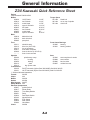
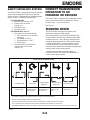
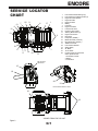
3 4 K350Z OPERATORS MANUAL Table of Contents General Information.................................................................................................. A Section Z34 Kawasaki Quick Reference Sheet................................................................... A-2 Warranty Information............................................................................................... A-3 Safety Precautions................................................................................................... B Section Z34 Operation.......................................................................................................... C Section Maintenance Information.......................................................................................... D Section Service Locator Chart............................................................................................. D-1 Electrical .................................................................................................................. E Section 34K350Z, 34K15Z Wire Harness Schematic.......................................................... E-1 Notes........................................................................................................................ F Section WARNING: THE ENGINE EXHAUST FROM THIS PRODUCT CONTAINS CHEMICALS KNOWN IN THE STATE OF CALIFORNIA TO CAUSE CANCER, BIRTH DEFECTS OR OTHER REPRODUCTIVE HARMS. IMPORTANT: A separate Engine Owner’s Manual is included with your owner’s packet which contains additional engine information that will not be repeated in this manual. You are highly urged to read it before attempting any operation or repair of the engine. Engine Owner’s Manual covers the engine manufactures warranty. General Information This manual covers the following equipment models: Warranty registration The Delivery and Warranty Registration form must be completed and signed to validate your Z34 – 34K350Z warranty protection. As the new equipment owner, you are expected to see that the form is completed To the new owner and forwarded to ENCORE MFG. CO., INC. at time of delivery. The purpose of this manual is to assist owners IMPORTANT: Any unauthorized modification, and operators in maintaining and operating the alteration, or use of non-approved attachments Encore Z34 mower and deck. Please read it voids the warranty and releases ENCORE MFG. carefully; information and instructions furnished CO., INC. for any liability arising form subsequent can help you achieve years of dependable service. use of this equipment. A separate Engine Owner’s Manual is included with your owner’s packet which contains additional Model and serial number engine information that will not be repeated in this manual. You are highly urged to read it Mower model and serial number are found on the before attempting any operation or repair of the engine. Engine Owner’s Manual covers the engine serial tag, located on the seat frame directly under seat plate. manufactures warranty. These numbers are required on the Warranty It is the owner’s responsibility to make certain Registration form. They will also assure you of the that the operator reads and understands this correct service parts when replacement becomes manual and all decals before operating this necessary. machine. It is also the owner’s responsibility to make certain that the operator is a qualified and Parts and Service physically able individual, properly trained in the operation of this equipment. Local regulations may Use original Encore replacement parts only. restrict the age of the operator. These parts are available through your local Encore dealer. To obtain prompt, efficient service, Using this manual always provide the following information when General operation, adjustment and maintenance ordering parts: 1. Correct part description guidance is outlined for both the experienced 2. Correct model number and novice Encore user. Operating conditions 3. Correct serial number vary considerably and cannot all be addressed individually. Through experience, however, operators should find no difficulty in developing good operating skills suitable to most conditions. Directions used in this manual, for example RIGHT or LEFT, refer to directions when seated on the mower facing forward unless otherwise stated. Photographs and illustrations used were current at the time of printing, but subsequent production changes may cause your machine to vary slightly in detail. ENCORE MFG. CO., INC. reserves the right to redesign and change the machine as deemed necessary, without notification. All warranty repair and service must be handled through an authorized Encore dealer. Arrangements should be made through your local service center. For location of nearest dealer look up our dealer search on our website: www.seriousred.com A-1 General Information Z34 Kawasaki Quick Reference Sheet Engine 15hp Kawasaki FH430V-AS23 Blades Torque Specs 423029 14.25" blade 14 1/8" 65 ft-lbs blade bolt 423014 low lift blade 14 1/4" 90 ft-lbs nut on top of spindle 423173 mulch blade 13 7/8" 50 ft-lbs clutch bolt 423210 super hi-lift blade 14 1/16" 603035 20" blade 20 3/16" 603041 low lift blade 20 3/16" 603055 mulch blade 20" 603056 super hi-lift blade 20 3/16" Belts 343018 blade drive belt 363210 deck drive belt 583385 pump belt Tires Front Caster Bearings 343111 wheel/tire assy 423200 bearing 343112 drive tire (18x7.5x8) 423201 bearing retainer 343113 rim w/ valvestem 363311 front caster complete 363260 front tire & tube (4.10/3.50-4) * * * * front rim not serviced Spindles Seat 583106 spindle assy comp. 423246 seat complete w/o tracks 583111 housing 583089 seat cushion 363350 bearing 583090 back cushion 583112 shaft 593097 molded arm rest 583113 brg. Spacer tube Transmission 343120 RH IZT transaxle (Hydro-Gear 328-2400R) Seal Kit # 343152 343121 LH IZT transaxle (Hydro-Gear 328-2400L) Seal Kit # 343152 *** lifetime lubricated transaxles Throttle 363352 Choke N/A Muffler 343019 Gasket 423324 Wire Harness 343077 Safety Module N/A Electrical Components 423027 Ignition Switch 423017 Starter Relay 583423 Time Delay Module 583351 Relay 523034 Park Brake Switch 823193 Neutral Switch 523031 PTO Switch 523030 Seat Switch 523283 Hour Meter Clutch 343084 A-2 ENCORE WARRANTY WHAT IS COVERED BY THIS WARRANTY This warranty extends to the original retail purchaser only and commences on the date of original retail purchase: 1. Residential use: The warranty will be Two years from the date of purchase against defects in workmanship and materials for any Encore rider that is used for consumer purpose. Normal residential use means use of product on owners’ property only. 2. Commercial use: The warranty will be Two year from the date of purchase and 90 days for rental use against defects in workmanship and materials for any Encore rider that is used for commercial purpose. 3. If the Purchaser discovers within this warranty period a defect in materials or workmanship: Purchaser must promptly notify an Authorized Encore Dealer and return the mower, including any defective parts, to an Authorized Encore Service Dealer. Encore Mfg. Co., Inc. will determine if material or workmanship is defective and then either repair or replace such parts. Service calls and/or transportation expense of the product to and from the authorized dealer, for warranty work, will be paid by the owner of the product. 4. Encore Mfg. Co., Inc. provides a limited warranty for 90 days from the date of purchase against defects in workmanship and materials for all parts, excluding normal wear items such as batteries, tires, and belts. 5. The Deck Shell warranty is Ten years from the date of purchase against defects in workmanship and materials for any Encore rider that is used for consumer and commercial use only. 6. NOTICE: Cutter housings, electrical components, hydraulic components and electric-clutch must be returned before warranty will be paid. 7. The engine warranty is covered by its respective manufacturer. Please refer to the manufacture’s warranty statement in the manufacture’s engine manual that is included in the literature packet. Engine warranties should be referred to the nearest authorized service outlet of the engine manufacturer. Encore Mfg. Co., Inc. reserves the right to change or improve the design of any mower without assuming any obligation to modify any mower previously manufactured. WHO MUST PERFORM THE WARRANTY SERVICE All warranty service will be performed by dealers authorized by Encore Mfg. Co., Inc. Service calls and/or transportation expense of the product to and from the authorized dealer, for warranty work, will be paid by the owner of the product. For warranty service you can contact an authorized dealer or contact: Encore Mfg. Co., Inc. PO Box 888 Beatrice, Nebraska 68310 1-800-267-4255 www.encoreequipment.com www.seriousred.com WHAT IS NOT COVERED BY THIS WARRANTY Encore Mfg. Co., Inc. does not warranty: Repairs made by unauthorized persons. Damage caused by use of the Encore equipment for purposes other than those for which it was designed Damages caused by disasters such as fire, flood, wind, and lightening. Damages caused by neglect, abuse, abnormal use, improper or unreasonable use, accident, negligence or misuse. Repairs or replacement resulting from the use of unauthorized parts, accessories or attachments. Repairs or replacement as the result of any alterations or modifications, in the determination of Encore, which adversely affects the operation, performance or durability of the equipment. Encore unit which has the serial number removed or made illegible. Depreciation or damage caused by normal wear, lack of reasonable and proper maintenance or failure to follow the product’s owner’s manual provided by Encore Mfg. Co., Inc. Normal maintenance parts and service including, but not limited to: filters, fuel, lubricants, tune-up parts, belts, blades, blade sharpening, brake or steering adjustments. Repairs necessary due to improper fuel, contaminates in the fuel system, or failure to properly prepare the fuel system prior to any period of non-use over three months. LIMITATION OF REMEDIES In no case shall Encore Mfg. Co., Inc. be liable for any special, incidental, or consequential damages based upon breach of warranty, breach of contract, negligence, strict liability in tort, or any other legal theory. Such damages include, but are not limited to Loss of profits Loss of savings or revenue Loss of use of Encore mower or any associated equipment Cost of capital Cost of any substitute equipment, facilities, services, or downtime The claims of third parties including customers, and injury to property Some states do not allow the exclusion or limitation of incidental or consequential damages, so the above limitation or exclusion may not apply to you. OWNER’S RESPONSIBILITY You must maintain your Encore Product following the maintenance procedures described in your owner’s manual. Such routine maintenance, whether performed by a dealer or by you, is at your expense. This machine, like any other powered equipment, is potentially dangerous unless properly operated. Any operator must be cautious and keep safety in mind at all times. Any operator, prior to using the Encore equipment, should thoroughly familiarize himself with the owner’s manual regarding operation and safety of the machine, as well as all safety warnings on the machine itself. ENCORE MFG. CO., INC. CANNOT BE RESPONSIBLE FOR THE WAY YOU OPERATE, OR THE CONDITIONS IN WHICH YOU OPERATE THE MOWER. USE COMMON SENSE AT ALL TIMES. WARRANTY REGISTRATION 1. The Warranty registration form MUST be completed and forwarded to Encore Mfg. Co., Inc. within fifteen days following date of purchase. 2. The date of purchase constitutes delivery. Encore Mfg. Co., Inc. does not assume or authorize anyone to assume for them any other obligation. A-3 ENCORE Your mower is only as safe as the operator! Operator carelessness or error may result in serious bodily injury. Improper maintenance of the machine may also result in injury. Please read and follow these instructions on Safe Operation and be certain that anyone using this mower fully understands and follows these instructions. Instructions are from ANSI Standard B17.4-2004. 7. Handle gasoline carefully. Use an approved gasoline container. Fill the fuel tank, to within 1” from the neck, with good quality unleaded gasoline. 8. Seat must be occupied and drive levers must be in the Neutral position and the Blade Clutch must be disengaged before starting engine. 1. Familiarize yourself with the controls and know how to stop the rider and mower deck quickly. 9. Operator must wear proper shoes and clothing, which may include safety glasses and ear protection. WARNING: DO NOT allow children to operate the machine. DO NOT allow any adult to operate the machine without proper instruction. 2. Inspect your work area carefully. Remove debris from the area to be cut. Keep all bystanders away from the mowing area. 10. Mow only during daylight hours or under very good artificial light. 11. The safety shield over the Grass Discharge area must always be bolted in place and in the DOWN position unless the Grass Catcher is being used. 3. Avoid contact with moving parts. Keep hands and feet clear of the mower deck. 12. If a solid object has been hit by the blades stop the machine and check for damage. Repair or replace any damaged / broken part prior to restarting the engine. 4. Never direct the discharge of material toward bystanders or allow anyone near the machine while in operation. 13. To avoid burns, DO NOT TOUCH the engine or muffler immediately after operation or during. 5. The machine is not intended for highway or street use. Never carry passengers! 14. Disengage blades when transporting and when crossing walks and gravel roads. 6. Never tamper with safety devices or guards. If a guard or safety device is damaged or removed, replace it before operating the rider. 15. DO NOT mow close to drop-offs, deep ditches or other hazards. DO NOT attempt to mow slopes grater than 15°, Always mow across the face of a slope NOT up and down. CAUTION: Never add fuel to the tank while the engine is running or hot. ALWAYS WAIT at least five minutes before refueling and REFUEL WITH THE ENGINE OFF. KEEP FUEL AWAY FROM SPARKS OR FLAMES. WIPE AWAY any fuel spillage BEFORE starting unit. Never fill the fuel tank indoors. Wipe up any spilled gasoline. Gasoline is highly flammable - NO SMOKING. 16. Reduce speed and exercise extreme caution on slopes and in sharp turns to prevent tipping or loss of control. Be especially cautious when changing direction on slopes. 17. The Encore Rider is NOT designed for towing. 18. Only factory approved Grass Collection Systems are permitted. 19. Shut off fuel while storing or transporting. Do Not store fuel near flames ot drain indoors. B-1 ENCORE STARTING ENGINE Before Operating Reminders Fill engine crankcase as per engine manufacturer’s manual. Engine DOES NOT have oil in crankcase from the factory. Add proper fuel to fuel tank, open shut-off valve. The battery is now a gel-cell and w ill not require acid. Before hooking up the ground wires make sure that the engine has been filled to the proper level with oil. If battery will not turn the engine over after hooking the wires up it may require a charge for 15 to 20 minutes. ASSEMBLY INSTRUCTIONS TO STOP ENGINE: move throttle lever to idle position and turn ignition key to “OFF” position. If engine has been working hard or is hot, allow engine to idle for a short period of time before turning off key. This practice will help cool engine before stopping. 1. Remove deflector chute, bolt bag and operator’s manual from main assembly. IN CASE OF EMERGENCY engine may be stopped by turning ignition key to “OFF” position. 2. Open bolt bag and lay out the following bolts: (8) 5/16” -18 x 3/4” HHCS (4) 5/16” lock washers (4) 5/16” nyloc nuts (4) 5/16” -18 whizlock nuts TO START ENGINE: occupy seat, set park brake, leave the motion control levers swung out, move throttle control lever all way to choke position. Turn ignition key to start position to engage starter, release the key when engine starts. Ignition switch is spring loaded and will return to run position automatically. Slowly return choke to run position once the engine has started. STOPPING ENGINE Remove unit from crate, taking care to remove inner boxes and the small parts box. Throttle control, ignition switch and choke control are located between motion control levers on the front panel under the front of the seat. Because of a built-in safety interlock system, your machine will not start unless the seat is occupied. 3. Taking four of the 5/16” -18 x 3/4” bolts and four of the 5/16” lock washers, attach the seat to the seat plate. 4. Using the remaining bolts and whizlock nuts, bolt the control levers onto the outsides of the mount angles, adjusting them according to operator comfort. CAUTION: Always remove the key and set the parking brake when leaving the machine unattended, even for just a few minutes. PREVENT ACCIDENTS: Do not give children or unauthorized persons an opportunity to operate this machine. 5. With the operator’s seat in the raised position locate the two lead seat switch wire located in the seat frame. Attach the two leads to the seat switch located on the under-side of the seat. 6. Fill engine crank case as per engine manufacturer’s manual. The engine DOES NOT have oil in the crankcase from the factory. 7. Raise the unit slightly and place a board under each rear wheel. With the deck in the raised position start the unit and drive it off the pallet. Once you are familiar with the contents of this manual, you are ready to mow with the finest mower built! WARNING: THE ENGINE EXHAUST FROM THIS PRODUCT CONTAINS CHEMICALS KNOWN IN THE STATE OF CALIFORNIA TO CAUSE CANCER, BIRTH DEFECTS OR OTHER REPRODUCTIVE HARMS. WARNING: DO NOT allow children to operate the machine. DO NOT allow any adult to operate the machine without proper instruction. C-1 ENCORE SAFETY INTERLOCK SYSTEM Your Encore Rider is equipped with a Safety Interlock System that is designed to help prevent possible serious injuries. Understanding and maintaining this system is vital, for maximum safe operation. TO START ENGINE: 1. Blades (PTO) must be “OFF”. 2. Control levers in neutral (swung out). 3. Park Brake “ON”. 4. Operator in seat. THE ENGINE WILL KILL IF: 1. The operator leaves the seat with: a. The control levers out of neutral (swung in). b. The blades on (PTO). c. The park brake is “OFF”. d. All the above. 2. The park brake is set before the control levers are in neutral (swung out) CORRECT TRANSMISSION OPERATION TO GO FORWARD OR REVERSE The Encore Rider is equipped with a pump/wheel motor unit for each wheel and are controlled with “Motion Control Levers” , one for each wheel. See Figure 1 MOWING SPEED The Encore Rider is designed to operate most efficiently at maximum blade speeds. The running speed of the machine should allow the mower blades to maintain this maximum speed while mowing across turf. Use a slower ground speed for cutting tall grass, grass which is heavy with moisture, or when mowing uphill. If ground speed is too fast, or blade speed is too slow, mowing will be uneven because mower blades will not be able to lift grass into cutting position as the mower passes. Throttle control regulates speed of engine as measured in RPM. This control SHOULD NOT be used to control ground speed. AS SETTING IN THE DRIVER’S SEAT N N Forward Travel Push both levers forward evenly Pivot Turn Push one levers forward and other lever pull back Forward Travel Right Turn Push left lever forward more than the right lever Reverse Travel Right Turn Pull left lever back more than right lever Reverse Travel Pull back both levers evenly N = Neutral or Stopped Travel [ Return both levers evenly to the neutral position. ] Direction of arrows indicate direction of machine travel. The further the levers are moved away from the neutral position, the faster the machine will travel. To turn the mower LEFT or RIGHT, slow the speed of the wheel in the direction you want to turn. To CHANGE DIRECTION, slowly move levers to neutral and move the lever forward in the direction of travel you want to go. Figure 1 C-2 ENCORE SER VICE LOCATOR CHAR T 13 12 22 7 9 11 17 1 8 5 2 13 6 4 3 1 19 10 11 1. 2. 3. 4. 5. 6. 7. 8. 9. 10. 11. 12. 13. 14. 15. 16. 17. 18. 19. 20. 21. 22. Front Caster Wheel Bearings (2) Front Caster Pivot Bearing Zerks (2) Engine Oil Fill & Dipstick Engine Oil Filter Engine Air Filter Battery Fuel Tank Engine Fuel Filter Fuel Shut-off Valve Fender w/ Cup Holder Steering Block Zerks (2) Engine Vent Screen Drive Tires Pump Belt ( 583385 ) Blade Drive Belt ( 343018 ) Deck Drive Belt ( 363210 ) Tiltable Foot Plate Front Casters Wheels Starter Relay 20” Blade 14.25” Blade Located inside the seat frame under operators seat: 1. Time delay module 2. Relays 3. Fuse Block Belt Tensioner Adjustment 15 16 20 21 VIEWED FROM UNDER OF DECK 14 18 Figure 2 VIEWED FROM TOP OF UNIT D-1 ENCORE Lubrication MAINTENANCE INFO 1. Do not adjust mower or change attachments unless the engine has beenstopped and the key has been removed. 2. Good maintenance, wiping up gasoline and oil spills, will reduce potential fire hazards. The following recommendations on lubrication chart below should be adhered to. Environmental conditions may be cause to vary frequency. Grease points are pointed out in Figure 2. Description of Maintenance Task Service Intervals Blades - sharpen & securely fastened to 65 ft-lbs Daily Check fuel level Daily Discharge chute - securely in place & in lowest position Daily Verify safety start interlock system Daily Visually inspect tires Daily Visually inspect unit for loose hardware and/or damaged parts Daily Check battery connections Every 50 hours Check tire pressure with a guage Every 50 hours Check pump drive belt tension & condition Every 100 hours Check blade drive belt tension & condition Every 100 hours Check deck drive belt tension & condition Every 100 hours Tighten lug nuts on wheels Every 100 hours Check oil level in engine See Note A Change engine oil & filter See Note A Change fuel filter See Note A Clean air intake screen See Note A OIL AND FILTER Clean cylinder / head fins See Note A Clean foam element See Note A Since the hydraulic drives on the Z34 Rider are lifetime lubricated there are no required filter and or oil changes required. Please refer to the engine manual for engine lubrication recommendations. Clean paper element See Note A Replace air cleaner paper element See Note A Clean and regap or replace spark plugs See Note A 3. To insure that the mower will remain in safe operating condition, check and tighten all bolts, nuts and screws. Especially make certain the blade bolt/nuts are always tightened properly. 4. Never adjust governor on engine to a faster speed. The engine manufacturer adjusts the engine RPM to the proper setting. 5. Allow time for the engine to cool down prior to storing mower. Do not storemower or gasoline near any open flame or where gasoline fumes may be ignited. 6. Always replace worn or broken parts with genuine Encore repair parts purchased from an authorized Encore dealer. Using anything other than Encore repair parts may void all Encore factory warranties. CAUTION: Note: A. Refer to Supplied Engine Manufactures Owner’s Manual for all maintance and engine manufactures warranty policy information DO NOT SPILL OIL OR GREASE ON BELTS. TIRE PRESSURE This vehicle has been designed to achieve maximum operator comfort and ride. This cannot be achieved without proper tire pressure. A low pressure gauge is required to check the front tires. Front Tires - 14 PSI Rear Tires - 20 PSI NOTES: The Encore Rider is driven and steered by the rear wheels. REAR TIRE CIRCUMFERENCE DIRECTLY EFFECTS THE TRACKING OF THE MACHINE. If the machine will not drive in a straight line, check air pressure and adjust accordingly. D-2 ENCORE BATTERY Belt Adjustment The battery is located under the right hand fender to the rear of the machine. The gel-cell battery is maintenance free. Remove key from the ignition switch. The blade drive belt and the deck drive belt may be accessed by raising the foot plate. Each of these belts have an eyebolt for adjusting spring tension. See Figure 4. B A A: Deck Drive Belt Tensioner eyebolt B: Blade Drive Belt Tensioner eyebolt Figure 4 Spring tension should be maintained by having approximately 1/8” stretch between coils. By turning the nut on the eyebolt clockwise you increase the tension, counter clockwise will decrease tension. CAUTION: When servicing the battery or any other part of the electrical system, or if the battery must be removed for any reason, always, disconnect negative (ground) cable FIRST and reconnect it LAST to avoid possibility of electrical shorts. TO FRONT OF MOWER At temperatures below 32° F (0° C), full charge state must be maintained to prevent cell electrolyte from freezing and causing permanent battery damage. For longest service life, battery should be kept clean by wiping it off with a paper towel. Any corrosion around battery should be removed by applying a solution of one part baking soda to four parts water. A light coating of grease or petroleum jelly may be applied to all exposed terminal surfaces to prevent corrosion. BELT ROUTING Simplied View Blade Drive Belt 343018 Top View of the Deck Figure 5 When installing a belt please refer to the following figure 5 for routing the belt. D-3 ENCORE Tracking Adjustment The Encore Z34 riding lawnmower comes from the factory with the neutral setting already adjusted; however, the full-speed tracking will require checking. The full-speed tracking may be checked by operating the machine on a smooth level surface. If the machine tends to travel more to one side rather than in a straight line, the tracking requires adjustment. The tracking adjustment can be made by altering the position of the stop-plate located beneath the fuel tank/fender on each side of the machine. See Figure 7. The stop-plate limits the amount of stroke allowed on the steering lever. By rotating the stop-plate away from the linkage rod, the steering lever will be allowed to travel further thereby making that side faster. A Figure 6 Deck Height Adjustment Deck height adjustment can be attained by pressing down on the foot pedal and pulling the cut pin (A) out and repositioning it with the corresponding hole to the depth gauge label (See Fig. 6). Adjustments can be made in 1/4” increments from 1” to 4 1/2”. Leveling Deck The deck comes from the manufacturer pre-leveled. If the deck does not appear to be cutting level use the following procedure. When leveling the deck, you will notice there are four chains (B) that support the deck (See fig. 8) these are the points you adjust when you need to level the deck. 1. Set all tire pressures to the correct specification. Figure 7 2. Place machine on a level concrete surface. 3. Wearing heavy gloves, move blades by hand so they are pointing in the same direction. Measure from the blade tip (beveled edge to the ground. If there is more than 3/16” difference from one side to the other, the deck should be leveled. 4. Adjust deck height by loosening nut on deck lift chain and raising or lowering accordingly. Once you have achieved a difference of 3/16” or less retighten nut. B Figure 8 D-4 ENCORE Mower Blades Bypass Valve Check sharpness of mower blades after every 10 hours of operation. To sharpen blades proceed as follows: In some applications, it is desirable to move the machine for short distances at low speeds without operating the engine. Using (A) push the lever forward and then turn the knob (B) clockwise to lock lever in forward position. You will need to return the lever to its previous position prior to operating again. CAUTION: TURN OFF ENGINE AND REMOVE KEY BEFORE MAKING ANY ADJUSTMENTS. Block front end of mower up or run front up on ramps. Remove blade by turning bolt counter clockwise. B Blades should be discarded when worn excessively. See Sketch. .EW"LADE A 25 Degrees When Notch Starts Discard Blade Dangerous! Sharpen blade with a hand file, electric grinder or blade sharpener. Wear gloves and eye protection when sharpening. Grind blade at original bevel. Check balance of blade by positioning the blade on a nail or blade balance pedestal. Grind the blade on the end that is heavier until both sides balance. Do not wear loose fitting clothing which could get caught in moving parts. Always be sure to wear adequate protective clothing. Wearing safety glasses and safety shoes is advisable. Figure 10 Reinstall blades. Refer to Figure 9 for further information Important Note: Cup side of spring washer goes against blade. Blade Spring Washer Blade Bolt Figure 9 D-5 TO ENGINE GROUND RED 14 GA. ENGINE CHARGING BLACK 16 GA. E-1 N/C ABCDE F BLK/WHT 16 GA. BLACK 16 GA. BLK/WHT 16 GA. WHT / LT. GREEN 18 GA. YEL / LT. BLUE 18 GA. LT. GREEN 18 GA. N/O PARK BRAKE SWITCH 523034 N/C CLUTCH CONN. LT. BLUE 14 GA. Note: Only Function of module is delay on seat switch 30 YELLOW 18 GA. 86 87a 85 423017 STARTER RELAY 87 523031 CLUTCH SWITCH SEAT SWITCH 523030 HOUR METER 523283 BLACK 18 GA. GROUND TO ENGINE BLACK 14 GA. LT. BLUE/RED 18 GA. ENGINE KILL LT. BLUE 14 GA. RED /BLACK STP. 18 GA. RELAY 583351 REAR VIEW OF DELAY MODULE CONN. 583423 ORG / LT. GRN 18 GA. N/O K AC . BL GA 16 LT. BLUE/RED 18 GA. 15 AMP FUSE 20 AMP FUSE FUSE BLOCK RED 12 GA. TO POS. SIDE OF STARTER SOLENOID RED 12 GA. WIRE JUNCTION RED /BLACK STP. 18 GA. ORANGE 12 GA. 423027 IGNITION SWITCH 823193 NEUTRAL SWITCH LT. BLUE 14 GA. ENCORE ENCORE PART #: 343077 WIRE HARNESS FOR 34K350Z ; 15 HP KAWASAKI WIRE HARNESS FOR 34K15Z ; 15 HP KAWASAKI LT. BLUE/RED 18 GA. PURPLE 18 GA. LT. BLUE/RED 18 GA. WHITE 16 GA. Notes F-1 Notes F-2 Notes F-3 Notes F-4 0811 A ,ENCORE MANUFACTURING CO., INC. All rights reserved. Contents subject to change. Z SERIES 34K350Z - OPERATORS MANUAL Part Number 933236