1
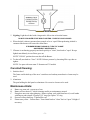
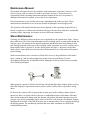
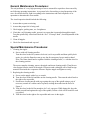
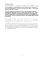
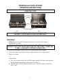
PRINCESS ALCOHOL STOVES
OPERATING INSTRUCTIONS
READ THESE INSTRUCTIONS BEFORE
OPERATING STOVE
WARNING: THIS STOVE USES HIGHLY FLAMMABLE FUEL,
USE GREAT CAUTION WHILE FILLING OR OPERATING IT.
Operation
1. Filling. Remove cap and fill with approved marine stove alcohol. Tank contains
approximately U.S. quart.
WARNING: DO NOT FILL TANK WHILE BURNERS ARE HOT OR FLAME IS
PRESENT. FUEL COULD IGNITE AND CAUSE FIRE. USE A SMALL FUNNEL AND
A SMALL CONTAINER TO PREVENT OVER-FILLING.
2. Replace cap and tighten securely. If any fuel is spilled, remove before lighting
3. Close both alcohol control knobs clockwise, pointer should be near "closed" position.
4. Pump 20-25 strokes
Preheat burners.
A. Turn valve to open position. Fuel will fill the upper chamber of the burner and drip down
into the priming ring at the base of the burner (See Figure 1)
B. When the ring is 1/2 full, turn burner knob to "close". Fuel will continue to drip down
until 3/4 full.
-1-
5. Lighting. Light the alcohol with a long match. Allow time to heat the burner.
DO NOT LEAN OVER STOVE WHILE LIGHTING - FLARE UP COULD OCCUR
6. When alcohol is almost consumed turn control valve to ‘open' When preheating alcohol is
consumed the burner will burn with a blue flame.
IF BURNER BEGINS FLARING UP, TURN TO "CLOSE"
AND PREHEAT ADDITIONALLY.
7. If burner is not burning properly turn knob quickly to "clean", then back to "open". Keep a
lighted match handy in case flame goes out.
NOTE "CLEAN" position does not shut off the Burner.
8. To shut off, turn knob to "close". NOTE: Release pressure by loosening filler cap. then retighten.
NOTE. Use pans with max mum 8" diameter on P35 models.
Care And Cleaning:
1. Stainless Steel
The frame and alcohol top of the stove’s stainless steel and any non abrasive cleaner may be
used.
2. Aluminum
The part holding the dial panel as aluminum. No corrosive cleaners to be used.
Maintenance Hints:
A.
B.
C.
D.
E.
Burner cap turns red - tap on top of can.
Burner will not shut off - Adjust cleaning needle per maintenance manual.
Pump does not resist when pumping - Remove pump, soak with Neatsfoot oil, work leather
with fingers and reinstall. If pump is "O" ring type replace "O" ring.
Pressure will not build up - Tighten filler cap.
Flame turns yellow - Preheat more. Turn control knob to "clean" back to "open". Relight if
necessary.
-2-
Maintenance Manual:
This manual is design to be used by mechanics with maintenance experience, however, it will
also be of great value to owners who wish to repair their own stove. It must be used in
conjunction with the operating instructions and parts manual for the stove in question. If
additional information is required, write to the service department.
Princess marine stoves use alcohol or kerosene, depending on the model you have. These
instructions are intended to cover all stoves because the principles involved apply to all.
The operation of the alcohol and kerosene stoves depends on the vaporizing of liquid fuel in a
burner or vaporizer so it burns with maximum efficiency. Because these fuels have considerable
variation in their vaporizing, the burners are also of different construction.
Stove Maintenance:
Generally, the differences between the two are recognizable by the construction. Figure 1 shows
these differences. The fuel is routed through a section of tubing, which is preheated to change the
liquid to vapor. The amount of fuel must be preheated, and therefore how much tubing it must
pass through, depends on the type of fuel. Alcohol, which evaporates very easily, requires only a
short length of tube to vaporize it. See the #209N burner in Fugure 1. Kerosene, on the other
hand, requires a great deal more heat, thus the #206 burner has a set of four tubes which permit
greater heating.
Most kerosene burner stoves can also use Diesel fuel, however, the possibilities of the burner
tubes “coking up” and becoming plugged are greatly increased with Diesel #2. Some
quicklighter problems may be experienced also, although even Diesel #2 has been successfully
used with the quicklighter.
When properly vaporized, all fuels tend to burn with a bright blue flame without smoke and very
little odor. Improper vaporization tends to produce yellow, smoky flames and produce strong
odors.
In all cases the vaporized fuel is sprayed into an open space before striking a burner plate or
burner top. Here it is mixed with air to become a combustible mixture which burns efficiently.
Many factors that tend to change with this mixture will produce abnormal operation. Incorrect
pressure, type of fuel, preheating, nipple orifice or fuel flow will cause this. In addition, changes,
disturbances in the flow of the fuel/air mixture due to damages tubes, dirt or clogging can disrupt
the burning pattern. The mechanical problems that cause these conditions are found in the
troubleshooting section.
-3-
General Maintenance Procedures:
The real problems of a very high percentage of stoves returned for repair have been caused by
not following operating instructions. As a general rule, after making a visual inspection of the
stove for obvious defects, light it according to the instructions and check all phases of its
operation to determine the exact trouble.
The visual inspection should include the following:
1. Assure that no parts are missing
2. Assure that proper fuel is being used.
3. Check nipples, packing nuts, etc. for tightness.
4. If unit has a self-cleaning needle, operate it to assure that it protrudes through the nipple.
Turn the spindle fully closed and check the “feel”. If it stops “hard”, check adjustment of the
needle.
5. Clean all nipples.
6. Check for deteriorated tank cap seal.
Special Maintenance Procedures:
1. Cleaning the nipple:
A. Stoves with self-cleaning needles:
Turn the wheel to the left (counter-clockwise) as far as possible and then quickly back
again. As a rule the flame does not go out, but for emergency keep a match at hand.
Note: The flame should not be regulated with the cleaning needle, i.e. with the wheel in
the cleaning position.
The assure complete cleaning, remove the nipple and insert cleaning needle. Then blow to
clear foreign from the inside of the nipple. Pressurize tank with nipple off to flush foreign
material from inside the evaporator or burner. Replace nipple and tighten securely.
2. Replacing the cleaning needle:
A. Screw out the nipple with a key or wrench.
B. Turn the wheel to the left and take out the cleaning needle. Then turn the wheel back to
the right as far as possible.
C. Put the new cleaning needle with cogs against the cogs of the spindle using a pair of
tweezers (a match or a rubber end of a pencil) sticking the needle into the end of it.
Figure 2.
D. Turn the wheel to the left far enough to let 3 or 4 cogs pass. While doing this, keep the
needle pressed hard against the cogs of the spindle, so that a click will be heard for each
cog passed.
E. Turn the wheel to the right as far as possible and screw in the nipple.
-4-
If the cleaning needle is put in correctly, it should be visible in nipple hole after turning the
wheel not more than 1/3 turn to the left from closed position.
3. To replace the spindle packing:
The procedure is the same as when replacing the cleaning needle. Screw out the nipple and
take out the cleaning needle. Screw out the box nut and the spindle. Replace the packing.
-5-
Troubleshooting Guide:
Symptom. Leakage around tank, lines, quicklighter, burner
1.
2.
3.
4.
Problem
Loose connections.
Damaged fittings.
Holes in tank or soldered joints.
Leakage around burner spindle.
1.
2.
3.
4.
Corrective Action
Tighten.
Replace fittings.
Replace.
Tighten, replace packing, replace spindle.
Symptom. Burner will not shut off
Problem
1. Cleaning needle maladjusted.
1.
2. Foreign material in evaporator.
2.
3. Bad spindle.
4. Bad burner or evaporator..
3.
4.
Corrective Action
Remove and adjust per instructions.
Note: if need is bottoming on evaporator
body, holding the spindle from closing, it
can be felt by turning rapidly to the closed
position. It will stop with a very “hard”
feel.
Remove nipple needle, open spindle,
pressurize tank and flush evaporator.
Replace nipple.
Replace.
Replace burner or evaporator.
1.
2.
3.
4.
Corrective Action
Clean or replace nipple and needle.
Adjust per instructions.
See low pressure symptom.
Replace nipple.
Symptom. Weak flame
1.
2.
3.
4.
Problem
Clogged nipple.
Maladjusted cleaning needle.
Low pressure.
Wrong nipple installed.
Symptom. Unbalanced flame
Problem
1. Dirty nipple.
2. Bad nipple.
3. Threads misaligned between burner cup
and nipple.
4. Bent burner cup.
-6-
Corrective Action
1. Clean or replace.
2. Replace.
3. Replace evaporator.
4. Replace.
Symptom. Erratic Flame
Problem
1. Debris in evaporator or burner.
Corrective Action
1. Remove nipple, needle, open spindle,
pressurize tank and flush evaporator,
replace nipple.
Symptom. Low pressure in tank
1.
2.
3.
4.
5.
Problem
Air screw not tight.
Bad seal in tank cap.
Cap relief valve leaks.
Tank cap not tight.
Pump chatters or provides no resistance.
1.
2.
3.
4.
5.
Corrective Action
Tighten air screw.
Replace seal or cap.
Replace cap.
Tighten.
A. Spread leather cup on pump piston,
soak in kerosene or light oil and replace.
B. Change pump leather or o-ring.
C. Change pump check valve.
D. Tighten pump tube (535/155.)
Symptom. Pressure drops off too fast
Problem
1. Tank too full of fuel.
(Tank must be less than ¾ full)
2. Pressure release screw not tight.
3. Leak.
Corrective Action
1. Remove some fuel.
2. Tighten.
3. See (I) above.
Symptom. Burner will not light
1.
2.
3.
4.
5.
6.
Problem
No fuel.
No air pressure.
Incorrect fuel.
Bad evaporator or burner.
Plugged nipple.
Broken control spindle.
1.
2.
3.
4.
5.
5.
Corrective Action
Refuel.
Pump up or see symptom, low pressure.
Replace with correct fuel.
Change evaporator or burner.
Clean or replace.
A. Replace spindle.
B. Replace burner/evaporator.
Symptom. Flame blows too far away from burner head
Problem
1. Too high pressure.
2. Incorrect fuel.
Corrective Action
1. Release partial pressure.
2. Check fuel and change.
-7-
Princess P35 Spares Parts List:
-8-
2365
2455
2459
P6060
P6065
P8070
P8275
P8282
P8290
P8293
P8299
P8330
P8338
P8345
P8443
P8525
P8290
P8906
P8951
P8953
P8955
PUMP VALVE, COMPLETE
CLEANING NEEDLE
CLEANING NEEDLE
TANK ASSEMBLY
WASHER, PUMP MOUNT
NUT
PUMP ROD ASSEMBLY
EXTRUSION
CONTROL KNOB
PUMP VALVE, COMPLETE
DIAL PANEL
CUTTING BOARD
TANK ASSEMBLY
ANGLE DRIVE COUPLING
NUT
WASHER PUMP MOUNT
CONTROL KNOB
POST, GRILL MOUNTING
GASKET BOWL SEAL
BUSHING, BOWL SEAL
WASHER, BURNER PLUG
LOWER
P8956 BURNER ATTACH PLUG
P8960 NUT, BOWL SEAL
207B KEROSENE BURNER P35K
WITHOUT WHEEL
209N ALCHOL BURNER P35A
2044 TANK LID, COMPLETE WITH
PACKING
2078 PACKING FOR TANK LID
2094 GRAPHITE PACKING
TIGHTENING CONE
2162 FILTER
2180 INNER CAP
2183 OUTER CAP
2184 OUTER CAP
2188 INNER CAP
2191 VALVE NEEDLE
2193 PACKING NUT
2197 SPLIT PIN
2213 AIR TUBE
2221 WASHER
2225 INNER VALVE SPRING
2261 LEATHER CUP
2265 WASHER
2267 PISTON ROD NUT
2271 PUMP LID
2280 PUMP KNOB
2291 PUMP ROD WITH PISTON
Parts Source:
A&H Enterprises
1562 Parkway Loop, Suite A
Tustin, CA 92780
Ph: 714-258-2525 Fax: 714-258-7077
http://packstoves.com
A & H offers a full-service repair center for all makes and models of camping equipment,
including stoves, lanterns and other gear. A fully stocked parts department allows for fast and
efficient repair of your equipment. A & H accepts shipment of items and returns the repaired
items with a minimal amount of "turn around" time.
-9-
Wavetec Stove Catalog Information:
Introduction
SeaWard and similar alcohol fuelled stoves actually burn alcohol vapor. The liquid alcohol you
pour into the tank is transformed into its gaseous state by boiling. This boiling action takes place
in the base of the burner. The burner must of course be hot – about 180oF for proper operation.
In order to start a cold burner, it must therefore be preheated above the boiling point of alcohol if
it is to produce the required vapor.
The preheating operation is an extremely important step in obtaining satisfactory stove
performance. We will say more about this in a moment. The recommended fuel for galley stoves
is 95% pure denatured ethyl alcohol. It can be found labeled as “alcohol stove fuel” (not to be
confused with gasoline “stove fuel”), or “denatured alcohol shellac thinner”.
Satisfactory operation is also obtained with 91% isopropyl alcohol if it contains less than .003%
non-volatile material. We find that most difficulties experienced with stove operation can be
traced to impure fuel. Not recommended are wood alcohol, methanol or rubbing alcohol as they
will not burn satisfactorily and will probably clog the fuel filters in the burners.
To start a pressure type alcohol stove the chosen fuel will be poured into the stove tank through
the fuel fill nipple. Note that this nipple has a rather special cap. It includes a pressure relief
valve that effectively prevents excessive pressure build up in the tank. The cap must never be
replaced by any other type.
A pump, placed near the front center of the stove is used to pressurize the fuel tank, thereby
pushing the fuel up through the burners. Satisfactory operation is usually obtained with the fuel
pressurized between 8-15 lbs per square inch. This takes about 15 to 20 strokes of the pump. The
exact number of strokes required for operation will vary depending on the amount of fuel in the
tank and the condition of the burners. In some instances a few more strokes may provide even
better burner operation.
The burner controls are located on the front flange of most stoves. Clockwise rotation of the heat
control knob closes off the fuel in the burner. Counter clockwise rotation of the knob will open
the jet allowing more fuel to flow. The extreme counter clockwise position is the “clean”
position where the internal mechanism of the burner causes a small wire to push through the
burner nozzle, removing any dirt which may have lodged there. The maximum heat position for
this control is usually about half way between the “off” and “clean” positions.
- 10 -
Operation
To start the stove fill the tank about 3/4 full with denatured ethyl alcohol. Use a funnel. Replace
the filler cap and tighten snugly. Pump 15 – 20 times to pressurize the tank. Next open the burner
heat control knob allowing liquid alcohol to flow through the burner and dribble down into the
preheating cup at the base of the burner. Close the burner control to its off position after about 3
or 4 seconds. About 3 tablespoons of alcohol will have overflowed the burner and trickled down
into the cup or indentation at the base of the burner.
Now with the burner still “off”, ignite the alcohol in the cup. As the burner is warmed by the
flame, the liquid alcohol trapped in the burner boils, causing a flame to appear at the burner cap
as well. This will produce a relatively high flame at the burner for a brief period. Too much
alcohol used for the preheat operation will produce a higher flare up than required but too little
will not bring the burner to a high enough temperature.
The preheating flame should probably burn for 2 – 3 minutes. When the preheating alcohol is
completely consumed, open the burner control and light the vapourized fuel at the burner cap. A
hot burner will produce a hissing sound when turned on. A cold burner will be silent or produce
a squirting noise followed by liquid alcohol flowing down into the lower cup.
After the preheating operation the upper burner must be lit without delay, before it cools off, or
further preheating will be necessary. Attempts to ignite a cold burner will cause flare-ups that are
quite worrisome to the “galley slave”.
Place your cooking utensils over the burner only after you are sure it is functioning properly. A
normally operating burner will exhibit a flame having several stacked rows of little blue flame
tips. There should not be a consistent yellow tip on the flame.
Adjustment of the air/fuel ratio of the burner to produce flames having the required appearance
will result in the most efficient fuel burn. The adjustment is accomplished by rotating the burner
flange with a pair of pliers until the yellow flame tips are eliminated. See figure (1).
A correctly adjusted burner will boil 2 cups of water in an open pan in approximately 8 minutes.
- 11 -
Troubleshooting
Pressure alcohol stoves are generally trouble free for long periods of time if kept free of dirt and
other fuel contaminants. Occasionally, however, a small flame mat appear where the heat control
system enters the burner. Tighten the gland nut at this point slightly until the flame no longer
appears. This adjustment may be necessary on a new stove after a few hours of burner operation,
and thereafter at infrequent intervals.
Should the pump bounce back when you try to pump or if the pump handle is pushed back
towards toy after a pump stroke, the check valve in the fuel tank is probably clogged, usually a
result of dirty fuel. Replacement of the check valve is relatively simple with the correct tool
providing no one has had a go at it with a pair of pliers. A little trick we use is with the correct
tool try tightening the valve a wee bit first to break the seal, then turn in the opposite direction to
remove the valve.
If your pumping produces little or no pressure in the tank check the u-cup on the bottom of the
pump shaft. Replacement of this part takes about 30 seconds. Should the burner light properly
but go out after a short time you may be out of fuel or you didn’t pump enough or your filler cap
leaks. In the latter case, replace the rubber gasket or relief valve assembly.
If no alcohol comes through the burner when you attempt to start the preheat operation, either
you have no pressure in the tank or a filter has been clogged by dirty alcohol. Replacement of
this filter is accomplished by removal of the burner from the stove and in most cases it will be
found necessary to drill out the old filter assembly. This is a time consuming job requiring some
care to assure the burner is not damaged. We would recommend this operation be accompanied
by a complete burner overhaul.
- 12 -
Burner Overhaul
A 2 burner stove takes about 1 ½ hours to complete a factory authorized overhaul. The
procedure for those wishing to perform this maintenance themselves is as follows:
1. Start by completely removing all fuel from the tank, then remove the burner assembly by
following these steps.
2. Remove the pin in the stem of each heat control (see figure 2) to disengage the control shaft
from the burner.
3. After pulling out the control shaft, remove the fuel pipe connected to the base of the burner.
4. Next remove the burner from its base and position it upside down in a vice. Clamp the vice
jaws on the lower burner body. For models having an internal sintered filter, use an 11/64”
drill bit and bore into the exact center of the filter element to a depth not exceeding 5/8”.
Don’t go any deeper as this could damage the burner assembly beyond repair. From time to
time as you drill, remove the burner from the vice and attempt to tap the filter element out of
the burner base.
5. After it has been removed carefully clean out all foreign particles from the base of the burner.
Be sure nothing remains in there that could eventually clog the jets or nozzle.
6. If the burner is to be completely overhauled while it is apart, remove the outer burner cap on
top by prying up with the corner of a screwdriver, then lift off the inner burner cap.
7. Now you may unscrew the burner nozzle. An exact fitting wrench is recommended.
8. Remove the cleaning needle that is now visible, by turning the burner valve spindle counter
clockwise. This will disengage the gear teeth of the cleaning needle from the valve spindle.
The cleaning needle will now drop out if the burner is turned upside down.
9. Next, unscrew the gland nut from the burner body using a 3/8” wrench, and then turn the
burner valve spindle counter clockwise until its threads disengage from the burner body. At
this point the spindle can be pulled out. The internal packing and washers will come out with
the valve spindle.
10. You are now ready to install the new filter and any other parts required for the overhaul.
Make sure the burner is free from foreign matter inside before pushing the new filter into the
burner base. The new filters are rolled screen which fits quite snugly in the space formerly
occupied by the sintered filter.
11. To install a new valve spindle insert it into the burner and screw it in as far as it will go. The
gear on this valve spindle should show all the way across one side of the top hole in the
burner body.
12. Push in the washers and packing following the same sequence as in the original and re-install
the gland nut. Rotate the control stem back and forth while tightening the gland nut until the
packing is sealed and a slight but definite resistance can be felt when turning the control
stem.
13. Installation of a new cleaning needle is accomplished in the following manner. Turn the
control stem clockwise until the burner is closed and the needle valve is seated. Then put the
cleaning needle into the top of the burner with the needle point up and the teeth facing the
gear on the valve spindle.
Rotate the burner control knob very slowly in a counterclockwise direction while lightly
pushing the cleaning needle down into the burner. The lowest rack tooth will be resting
- 13 -
against the gear teeth of the valve spindle. As each gear tooth moves by a click can be heard
and a slight jolt felt through the cleaning needle. Stop turning the valve spindle after 5 clicks
are produced.
Now rotate the control stem slowly clockwise so that the cleaning needle rack and valve
spindle teeth engage. As the control stem is rotated still further to clockwise to the close or
“off” position the cleaning needle will be drawn down into the burner. No increase in
resistance should be felt during this operation. If the needle jams it will have to be removed
and the previous step repeated.
Note that when the burner valve is fully closed the top tooth of the cleaning needle rack
should remain above the center of the gear on the valve spindle. If the cleaning needle is too
deep in the burner it may bottom out before the needle valve is closed completely. This
would produce inability to completely shut off the burner. If you are not sure repeat the
procedure of installing the needle, being certain that only 5 clicks are heard during
installation.
14. You are now ready to install the nozzle in place – tighten it firmly. As a check, turn the valve
spindle to its fully closed position and then counterclockwise until it stops. This should be
just over half a turn of the valve spindle. If less than half a turn is found from “off” to “clean”
positions the cleaning needle has not been properly installed and that portion of assembly
should be performed again. In the “clean” position, that is fully counterclockwise, the
cleaning wire will be seen protruding slightly through the nozzle hole.
15. Complete the burner overhaul by placing the inner cap in position on the burner. The outer
cap may then be snapped into place. A slight tap with a wooden block or screwdriver handle
may be required to seat the cap.
16. You are now ready to re-install the burner. A new copper washer for the base is
recommended. Tighten the burner until the copper washer just begins to be compressed.
From this point the burner must be turned at least half a turn to make a tight seal and then
further until the valve spindle is pointing towards the control knob shaft.
17. From here on, re-assembly is the reverse of the disassembly procedure previously discussed.
After assembly of the stove, pressurize the fuel system and check for any fuel leaks at the burner
base or piping to the fuel tank. If all is well, proceed through the preheat operation to adjustment
of the fuel/air ratio of the burners. You will now find your pressurized alcohol stove to be
operating in “as new ” condition and should give you safe and satisfactory operation for many
years.
- 14 -