1
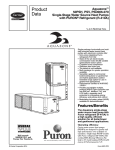
58MVB INFINITY™ 96
DELUXE 4---WAY MULTIPOISE VARIABLE---SPEED
TWO---STAGE CONDENSING GAS FURNACE
Series 120 Input Rates: 40,000 thru 120,000 Btuh
Product Data
Comfort Heatt technology, the ultimate in
heating comfort . . .
A05069
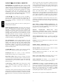
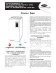
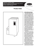
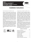
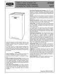
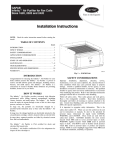
The Carrier Infinityt 96 with Comfort Heatt technology
achieves the optimum combination of comfort and efficency.
The Infinityt 96 achieves industry--leading ultra--high efficiency
at up to 96.6 percent Annual Fuel Utilization Efficiency (AFUE).
Efficient performance is enhanced through the variable--speed
design. To maintain ideal comfort, Comfort Heatt technology
automatically adjusts the heating level, maximizing the use of low
heating levels that produce near silent furnace operation while
meeting the exact heating needs. This unit is designed to keep the
indoor temperature within less than 1 degree of the thermostat
setpoint. Because it operates in low heat most of the time, the
Infinityt 96 uses up to 80% less power than single--capacity
furnaces.
In addition to providing ultimate comfort, the Infinityt 96 has a
sealed combustion system. This system brings combustion air to
the furnace and vents flue gases outside the furnace in a safe
manner. Because it is sealed, operational noise is minimal. A sealed
combustion system also means fewer cold drafts and less air
infiltration.
The Infinityt 96 is available in 6 heat/airflow combinations. The
unit has a 4--way multipoise design and can be installed in upflow,
downflow, or horizontal positions covering up to 24 different
applications. The Infinityt 96 can be vented as a Direct
vent/2--pipe furnace or as a non--direct vent/1--pipe application.
The versatile 4--way multipoise design in conjunction with variable
speed makes the Infinityt 96 ideal for use with split system
cooling, including 2--speed units. A Carrier Infinityt air purifier,
humidifier, comfort ventilator, and Comfort Zone II control will
provide year round comfort and efficiency.
Designed for durability, comfort, and reliability, the Infinityt 96 is
the ultimate in versatile, efficient comfort.
Carrier Infinityr System — When the Infinityt 96
variable--speed gas furnace is matched with the Infinityt Control
and an air conditioner or heat pump, the homeowner will
experience the ultimate in Comfort Heatt and IdealHumidityt
through unparalleled control of temperature, humidity, indoor air
quality, and zoning. The Carrier Infinityt System also provides
unprecedented ease of use through onscreen, text--based service
reminders and equipment malfunction alerts.
For even greater comfort and convenience, match the Infinityt 96
furnace with an Infinity air conditioner or heat pump. This will
create a fully communicating system, requiring only 4 thermostat
wires between system components. In some cases, troubleshooting
can even be done from the outdoor unit without entering the home.
Optional remote access through telephone or Internet is also
available when combined with a remote connectivity kit.
1
INFINITYT 96 FEATURES / BENEFITS
IdealHumidityt—The IdealHumidity system actively controls
both temperature and humidity in the home to provide the best
comfort all year long. Other systems depend on heating or cooling
demand to manage the moisture in the air. But, IdealHumidityt
gives the homeowner the right amount of humidity day and night,
even in mild weather. No other manufacturer can do this!
IdealHumidity saves energy, too. By keeping humidity under
control, the homeowner can set their thermostat to stay comfortable
and save energy—up to 20% off their cooling costs!
58MVB
Comfort Heatt—On the coldest days of the year, the Infinityt
96 Furnace has the capacity to heat the home. On moderate days
when less heat is required, this furnace will regulate itself to a
lower capacity—providing a comfortable home and minimizing
operating costs.
The patented algorithm adjusts the low heat operating time to
match the indoor conditions.
Reliable Heat Exchanger Design—The primary heat exchanger is
made of aluminized steel for corrosion resistance. The patented
Serpentufft condensing heat exchanger cells are laminated with
polypropylene for greater resistance to corrosion and epoxy coated
externally to prevent oxidation. This break--through in heating
technology helps extend the life of the furnace for years of
dependable performance. The heat exchanger is positioned in the
furnace to extract additional heat. Stainless steel coupling box
componentry between heat exchangers has exceptional corrosion
resistance in natural gas and propane applications.
Power Heatt Igniter—Carrier’s unique SiN igniter is not only
physically robust but it is also electrically robust. It is capable of
running at line voltage and does not require complex voltage
regulators as do other brands. This unique feature further enhances
the reliability of Infinityt 96 gas furnace and continues Carrier’s
tradition of technology leadership and innovation in providing a
reliable and durable product.
ComfortFant—Improves comfort all year long by allowing
selection of the continuous fan speed right at the thermostat.
SmartEvapt—Allows the system to reduce summertime
humidity levels by nearly 10% over standard systems.
Media Filter Cabinet—Enhanced indoor air quality in the home
is made easier with our media filter cabinet—a standard accessory
on all deluxe furnaces. When installed as a part of the system, this
cabinet allows for easy and convenient addition of a Carrier high
efficiency air filter.
Comfort Heatt Control Center—The microprocessor control
center features state--of--the--art combustion, temperature, and
airflow control to maximize comfort while operating at peak
efficiency.
Combustion control is obtained by taking the inducer motor RPM
reading when the medium--heat pressure switch makes. Using this
information, the microprocessor maintains a consistent air--to--fuel
ratio independent of vent sizing and conditions during all phases of
heat.
The first cycle after power reset provides 16 minutes of low heat
before switching to high heat unless the room thermostat has been
satisfied. Subsequent thermostat cycles provide anywhere from 0
to 16 minutes of low or medium heat depending on the length of
the previous thermostat cycle.
Airflow control is accomplished by the microprocessor and blower
motor. The ECM blower motor is configured by the
microprocessor to react to changes in the static load on the air
delivery system. The ECM blower uses this information to deliver
correct airflow independent of variations in system restrictions.
(For example, dirty filter or zone damper changes during a cycle.)
A special dehumidification function allows direct input from a
thermidistat or humidistat. This input adjusts system airflow for
greater humidity removal and increased cooling comfort during
summer months.
Direct Venting or Optional Ventilated Combustion Air —The
Infinityt 96 can be installed as a 2--pipe (Direct Vent) furnace or
as a non--direct vent/1--pipe application. This provides added
flexibility to meet diverse installation needs.
Electronic
Variable--Speed
Motors—ECM
Motors
(Electronically Commutated Motor) provide variable--speed
operation to optimize comfort levels in the home year round. They
are also more economical to operate than standard motors.
Sealed Combustion System—Infinityt 96 brings in combustion
air from outside the furnace, which results in especially quiet
operation.
Insulation—Foil--faced insulation in heat exchanger section of the
casing minimizes heat loss.
Insulated Blower Compartment—The acoustical insulation
reduces air and motor noise for quiet operation.
Monoport Burners—The burners are finely tuned for smooth,
quiet combustion and economical operation.
Bottom Closure—Factory--installed for side return; easily
removable for bottom return.
Blower Access Panel Switch—Automatically shuts off 115--v
power to furnace whenever blower access panel is opened.
Quality Registration—The Infinityt 96 is engineered and
manufactured under an ISO 9001 registered quality system.
Certifications—The Infinityt 96, Model 58MVB units are CSA.
(A.G.A. and C.G.A.) design certified for use with natural and
propane gases. The furnace is factory--shipped for use with natural
gas. A C.S.A. listed gas conversion kit is required to convert
furnace for use with propane gas. The efficiency is GAMA
efficiency rating certified. The Infinityt 96 meets California Air
Quality Management District emission requirements.
These furnaces are not approved for installation in mobile homes.
2
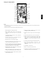
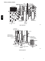
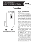
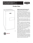
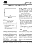
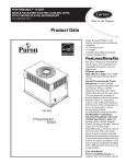
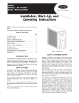
FURNACE COMPONENTS
13
1
2
3
4
5
14
6
6
7
9
15
17
18
19
8
10
11
12
A02287
NOTE:
S The 58MVB Furnace is built for use with natural gas. The furnace can be converted for propane gas with a factory--authorized and listed
accessory conversion kit.
S Control location and actual controls may be different than shown above.
11. Heavy--duty blower. Circulates air across the heat
exchangers to transfer heat into the home.
1. Burner sight glass for viewing burner flame.
2. Burner assembly (inside). Operates with energy--saving,
inshot burners and hot surface igniter for safe, dependable
heating.
12. Air filter and retainer. May be used for side return application.
13. Rollout switch (manual reset) to prevent overtemperature.
3. Combustion--air intake connection to ensure contaminant-free air (right or left side).
14. Primary serpentine heat exchanger (inside). Stretches fuel
dollars with the S--shaped heat--flow design. Solid
construction of corrosion--resistant aluminized steel means
reliability.
4. Redundant 2--stage gas valve. Safe, efficient. Features one
gas control with two internal shutoff valves.
5. Junction box for 115--v electrical power supply.
15. 3--amp fuse provides electrical and component protection.
6. Vent outlet. Uses PVC pipe to carry vent gases from the
furnace’s combustion system (right or left side).
16. Light emitting diodes (LEDs) on control center. Code
lights are for diagnosing furnace operation and service
requirements.
7. Secondary condensing heat exchanger (inside). Wrings out
more heat through condensation. Constructed with patented
Polypropylene--laminated steel to ensure durability.
17. ComfortHeatt Control Center.
18. Blower access panel safety interlock switch.
8. Pressure switches ensure adequate flow of flue products
through furnace and out vent system.
19. Transformer (24v) behind control center provides low-voltage power to furnace control and thermostat.
9. Inducer motor. Pulls hot flue gases through the heat
exchangers, maintaining negative pressure for added safety.
10. Condensate drain connection. Collects moisture condensed
during combustion process.
3
58MVB
16
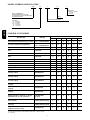
MODEL NUMBER NOMENCLATURE
58MVB
040
F
100
Cooling Airflow
(400 CFM per 12,000 Btuh)
14 --- 1400 CFM
20--- 2000 CFM
Deluxe 4--- Way Multipoise
Variable--- Speed Direct--- Vent (2--- Pipe)
or as a Non--- Direct--- Vent (1--- Pipe) Two--- Stage
Condensing Gas Furnace
Series
Media Filter Cabinet included
Input Rates
040 --- 40,000 Btuh
060 --- 60,000 Btuh
080 --- 80,000 Btuh
100 --- 100,000 Btuh
120 --- 120,000 Btuh
58MVB
14
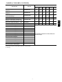
CARRIER ACCESSORIES
DESCRIPTION
UNIT SIZE
PART NO.
040---14 060---14 080---14 080---20 100---20 120---20
Vent Termination Kit (Bracket Only for 2 Pipes)
2---in. — KGAVT0101BRA
3---in. — KGAVT0201BRA
X
X
X
X
X
X
Concentric Termination Kit (Single Exit)
2---in. — KGAVT0701CVT
3---in. — KGAVT0801CVT
X
X
X
X
X
X
Condensate Freeze Protection Kit
KGAHT0101CFP
X
X
X
X
X
X
Condensate Neutralizer Kit (obtained thru
RCD)
P908---0001
X
X
X
X
X
X
Infinity Air Purifier
Model GAPA
X
X
X
X
X
X
Condensate Neutralizer Kit (obtained thru
RCD)
P908---0001
X
X
X
X
X
X
Electronic Air Cleaner
Model EACB
X
X
X
X
X
X
Mechanical Air Cleaner
Model FILCAB or EZXCAB
X
X
X
X
X
X
Humidifier
Model HUM
X
X
X
X
X
X
Heat Recovery Ventilator
Model HRV
X
X
X
X
X
X
Energy Recovery Ventilator
Model ERV
X
X
X
X
X
X
UV Lights
Model UVL
X
X
X
X
X
X
EZ Flex Media Filter with end caps --- 16---in.
(406 mm) (9 pack)
EXPXXLMC0016
EZ Flex Media Filter with end caps --- 20---in.
(508 mm) (9 pack)
EXPXXLMC0020
X
X
X
EZ Flex Media Filter with end caps --- 24---in.
(610 mm) (6 pack)
EXPXXLMC0024
Replacement EZ Flex Filter --- 16---in. (406 mm)
(10 pack)
EXPXXFIL0016
Replacement EZ Flex Filter --- 20---in. (508 mm)
(10 pack)
EXPXXFIL0020
Replacement EZ Flex Filter --- 24---in. (610 mm)
(10 pack)
EXPXXFIL0024
Exterior Filter Rack --- Universal, 1” (25 mm)
(adjustable from 14” to 24” () with filter
KGAFR0301ALL
KGAFR0306ALL
(6---pack)
X
X
X
X
X
Unframed Filter 3/4---in. (19 mm) — 16 x 25
(406 x 635 mm)
KGAWF1301UFR
KGAWF1306UFR (6 pack)
X
X
X
X
X
Unframed Filter 3/4---in. (19 mm)— 24 x 25 (610 KGAWF1501UFR
x 635 mm)
KGAWF1506UFR (6 pack)
X
Combustible Floor Base (Not required when
evaporator coil case is used.)
X
X
X
X
X
X
X
X
X
KGASB0301ALL
* Factory ---authorized and field---installed. Gas conversion kits are CSA (AGA/CGA) recognized.
S 16 x 25 (406.4 x 635.0 mm) filters suitable for side return on all furnace sizes.
X --- Accessory
4
X
X
X
X
X
CARRIER ACCESSORIES (CONTINUED)
UNIT SIZE
DESCRIPTION
PART NO.
Natural---To---Propane Gas Conversion Kit
(Single Kit)*
KGANP4601ALL
X
X
X
X
X
X
Propane---To---Natural Gas Conversion Kit
(Single Kit)
KGAPN3901ALL
X
X
X
X
X
X
ECM Motor Simulator (replaces the ECM motor
KGASD0301FMS
to aid troubleshooting
X
X
X
X
X
X
Door Gasket Kit
KGBAC0110DGK
X
X
X
X
X
X
Advanced Product Monitor (software and
hardware to link PC laptop to control board)
KGAFD0301APM
X
X
X
X
X
X
ECM Control Replacement Module --- 1/2 HP
HK44EA122
X
X
X
ECM Control Replacement Module --- 1 HP
HK52EA122
X
X
X
Gas Orifice Kit Size 42 (Qty 50)
KGAHA0150N42
Gas Orifice Kit Size 43 (Qty 50)
KGAHA0250N43
Gas Orifice Kit Size 44 (Qty 50)
KGAHA0350N44
Gas Orifice Kit Size 45 (Qty 50)
KGAHA0450N45
Gas Orifice Kit Size 46 (Qty 50)
KGAHA0550N46
Gas Orifice Kit Size 47 (Qty 50)
KGAHA1550N47
Gas Orifice Kit Size 48 (Qty 50)
KGAHA850N48
Gas Orifice Kit Size 54 (Qty 50)
KGAHA0850P54
Gas Orifice Kit Size 55 (Qty 50)
KGAHA0750P55
Gas Orifice Kit Size 56 (Qty 50)
KGAHA0850P56
Gas Orifice Kit Size 1.25mm (Qty 50)
KGAHA05750125
Gas Orifice Kit Size 1.30mm (Qty 50)
KGAHA5750130
See Installation Instructions for model, altitude, and
heat value usages.
* Factory ---authorized and field---installed. Gas conversion kits are CSA (AGA/CGA) recognized.
S 16 x 25 (406.4 x 635.0 mm) filters suitable for side return on all furnace sizes.
X = Accessory
5
58MVB
040---14 060---14 080---14 080---20 100---20 120---20
THERMOSTAT AND ZONING CONTROL OPTIONS
NON---PROGRAMMABLE THERMOSTAT SELECTION
TC ---NAC or TP ---NAC
For use with 1 speed Air Conditioner --- _F/_C, Auto Changeover
TC ---NHC or TP ---NHC
For use with 1 speed Air Conditioner --- _F/_C, Auto Changeover
TP ---NRH*
For use with 2 speed Air Conditioner --- _F/_C, Auto Changeover
* Model HP & 2 Stage thermostat must be field converted to air conditioner operation.
58MVB
PROGRAMMABLE THERMOSTAT SELECTION
TP ---PAC
For use with 1 speed Air Conditioner --- _F/_C, Auto Changeover,
7 ---Day Programmable
TP ---PHP*
For use with 1 speed Heat Pump --- _F/_C, Auto Changeover,
7 ---Day Programmable
TP ---PRH*
For use with 2 speed Air Conditioner --- _F/_C, Auto Changeover,
7 ---Day Programmable
TB ---PAC
For use with 1 speed Air Conditioner --- _F/_C, Auto Changeover,
5 ---2 Programmable
TP ---PRH{
For use with two---stage applications --- _F/_C, Auto Changeover,
7 ---Day Programmable
TP ---PRH}
For multi ---use/stage configurations --- _F/_C, Auto Changeover
7 ---Day Programmable
SYSTXCCUID01 ---B
Infinityt user interface
* Model HP & 2 Stage thermostat must be field converted to air conditioner operation.
{ Hybrid Heat™ thermostat is used with furnace and heat pump application.
} Thermidistat can be configured for heating, cooling, and Hybrid Heat applications. It must be configured for each specific application.
ZONING CONTROL SELECTION
ZONECC3Z(AC/HP)01
WeatherMaker Two---Zone Kit
ZONECC2KIT01 ---B
Comfort Zone II---B 2 ---Zone Kit
ZONECC4KIT01 ---B
Comfort Zone II---B 4 ---Zone Kit
ZONECC8KIT01 ---B
Comfort Zone II---B 8 ---Zone Kit
SYSTXCCUIZ01 ---B
Infinity Zone User Interface
SYSTXCCRRS01
Infinity Remote Room Sensor
SYSTXCCSMS01
Infinity Smart Sensor
SYSTXCC4ZC01
Infinity 4 ---Zone Damper Control
6
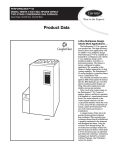
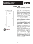
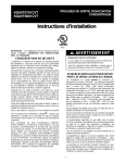
MODEL PLUG
CONNECTOR
USER INTERFACE
OR ADVANCED
PRODUCT
MONITOR
CONNECTOR
CONTINUOUS FAN
(CF) AIRFLOW
SETUP SWITCHES
OAT
CONNECTOR
SW4 SETUP
SWITCHES
SW1 SETUP
SWITCHES AND
BLOWER OFFDELAY
AIR CONDITIONING
(A/C) AIRFLOW
SETUP SWITCHES
HUMIDIFIER
TERMINAL (24-VAC
0.5 AMP MAX.
ACRDJ – AIR
CONDITIONING
RELAY DISABLE
JUMPER
24-V THERMOSTAT
TERMINALS
FLASH
UPGRADE
CONNECTOR
(FACTORY
ONLY)
STATUS AND COMM
LED LIGHTS
PL3 – ECM BLOWER
HARNESS
CONNECTOR
3-AMP FUSE
TRANSFORMER 24-VAC
CONNECTIONS
BOARD SERIAL
NUMBER
115-VAC (L2) NEUTRAL
CONNECTIONS
EAC-1 TERMINAL
(115 -VAC 1.0 AMP MAX.)
EXAMPLE:
V12 HK42FZ022 3407
SOFTWARE
VERSION
NUMBER
PART
NUMBER
115-VAC (L1) LINE
VOLTAGE CONNECTIONS
PL2 – HOT SURFACE
IGNITER & INDUCER
MOTOR CONNECTOR
DATE
CODE
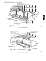
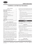
Control Center
Heat Exchanger
Inducer Assembly
;;;;;;;
;;;;;;;
;;;;;;;
;;;;;;;
;;;;;;;
;;;;;;;
;;;;;;;
______________________________________________________________________________________________________________
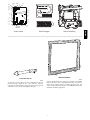
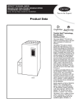
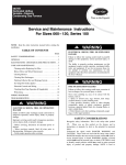
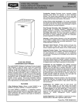
Downflow Subbase
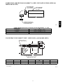
Concentric Vent Kit
A93086
A concentric vent kit allows vent and combustion--air pipes to
terminate through a single exit in a roof or side wall. One pipe
runs inside the other allowing venting through the inner pipe and
combustion air to be drawn in through the outer pipe.
A88202
One base fits all furnace sizes. The base is designed to be installed
between the furnace and a combustible floor when no coil box is
used or when a coil box other than a Carrier cased coil is used. It is
A.G.A. design certified for use with Carrier 58MVB furnaces when
installed in downflow applications.
7
58MVB
PL1 – LOW VOLTAGE MAIN
HARNESS CONNECTOR
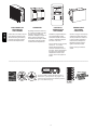
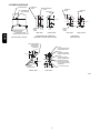
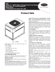
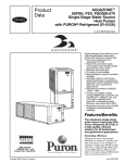
HUMIDIFIER
Cleans the air of smoke, dirt, and
many pollens commonly found.
Saves decorating and cleaning
expenses by keeping carpets,
furniture and drapes cleaner.
By adding moisture to winter-dry
air, a Carrier Humidifier can often
improve comfort and keeps
woodwork, wallpaper, and pain in
better condition. Moisturizing
household air also helps to retain
normal body heat and provides
comfort at lower temperatures.
CONTROLS:
THERMOSTATS
AND ZONING
Available in programmable and
non-programmable models,
Carrier thermostats maintain a
constant, comfortable temperature level in the home.
For the ultimate in home comfort,
Carrier‘s 2-, 4- or 8-zone
systems allow temperature
control of individual “zones” of
the home. This is accomplished
through a series of electronic
dampers and remote rooom
sensors. The 4-zone system is
shown.
ENERGY/HEAT
RECOVERY
VENTILATOR
Carrier‘s energy or heat recovery
ventilators exhaust stale indoor
air and provide fresh outdoor air
to the home while minimizing
heat loss and humidity level.
Especially useful for today‘s
tighter constructed houses.
Energy recovery ventilator is
shown.
______________________________________________________________________________________________________________
DE
C
ER
Always Ask For
S I GN
D
58MVB
ELECTRONIC OR
MECHANICAL
AIR CLEANER
TIFIE
CERTIFIED
Use of the AHRI Certified TM Mark indicates a
manufacturer’s participation in the program. For
verification of certification for individual products,
go to www.ahridirectory.org.
8
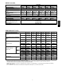
PHYSICAL DATA
Direct--- Drive Motor Hp (ECM)
Motor Full Load Amps
RPM (Nominal)—Speeds
Blower Wheel Diameter X Width --In. (mm)
Filter Size In. (mm) Nominal A
(Washable)
Shipping Weight (lb)
Limit Control
Heating Blower Control (Off Delay)
Burners (Monoport)
Gas Connection Size
Gas Valve (Redundant) Manufacturer
Minimum Inlet Pressure (in. wc)
Maximum Inlet Pressure (in. wc)
Ignition Device
UNIT SIZE
080---14
080---20
100---20
120---20
1/2
1
1
1
7.7
12.8
12.8
12.8
Variable 250 — 1300
11 x 10
10 x 7
11 x 10
11 x 10
11 x 10
11 x 10
(279 x 254)
254 x 178)
(279 x 254)
(279 x 254)
(279 x 254)
(279 x 254)
(1) 24 x 25 x 3/4 (1) 16 x 25 x 3/4 (1) 20 x 25 x 3/4 (1) 20 x 25 x 3/4 (1) 20 x 25 x 3/4 (1) 24 x 25 x 3/4
(610 x 635 x 19) (406 x 635 x 19) (508 x 635 x 19) (508 x 635 x 19) (508 x 635 x 19) (610 x 635 x 19)
205
170
182
204
203
234
SPST
Selectable 90, 120, 150, or 180 SEC Intervals
2
3
4
4
5
6
1/2--- in. NPT
White--- Rodgers
4.5 (Natural Gas)
13.6 (Natural Gas)
Hot Surface --- SiN
040---14
1/2
7.7
060---14
1/2
7.7
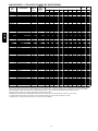
PERFORMANCE DATA
UNIT SIZE
CERTIFIED TEMP RISE RANGE
° F (° C)
040---14
25--- 55
(--- 4--- 13)
30 --- 60
(--- 1--- 16)
060---14
50--- 80
(10--- 27)
35 --- 65
(2--- 18)
080---14
50--- 80
(10--- 27)
35--- 65
(2--- 18)
080---20
50--- 80
(10--- 27)
35--- 65
(2--- 18)
100---20
50--- 80
(10--- 27)
45--- 75
(7--- 24)
120---20
50--- 80
(10--- 27)
45--- 75
(7--- 24)
Heating
0.10
0.12
0.15
0.15
0.20
0.20
Cooling
0.50
0.50
0.50
0.50
0.50
0.50
525
(620**)
785
500
(590**)
1070
705
(830**)
1490
685
(810**)
1530
875
(1030**)
1530
1180
(1390**)
1900
1390
1400
1375
1975
1950
2060
25000
25000
25000
38000
37000
37000
96.6
95
96.1
37000
36000
36000
57000
56000
56000
94.1
92.7
93.7
49000
49000
49000
75000
75000
75000
94.1
92.7
93.7
49000
49000
49000
75000
75000
75000
94.1
92.7
93.7
61000
61000
61000
94000
94000
93000
94.1
92.7
93.7
73000
73000
73000
113000
113000
112000
94.1
92.7
93.7
Low
26000
39000
52000
52000
65000
78000
High
40000
60000
80000
80000
100000
120000
Low
High
CERTIFIED EXT STATIC PRESSURE
(ESP)
Heating Low
AIRFLOW CFM‡
Low
OUTPUT CAPACITY
BTUH* (96)
High
AFUE%* Nonweatherized 96
INPUT BTUH†
Heating High
Cooling
(Max)
Upflow
Downflow
Horizontal
Upflow
Downflow
Horizontal
Upflow
Downflow
Horizontal
* Capacity in accordance with U.S. Government DOE test procedures.
† Gas input ratings are certified for elevations to 2000 ft. For elevations above 2000 ft, reduce ratings 2% for each 1000 ft above sea level.
In Canada, derate the unit 5% for elevations from 2000 to 4500 ft above sea level.
‡ Airflow shown is for bottom only return ---air supply with factory ---supplied 1 ---in. washable filter(s). For air delivery above 1800 CFM, see Air Delivery
Table for other options.
** Low--- and Medium ---heat CFM when low/medium heat rise adjustment switch (SW1 ---3) on furnace control is used.
9
58MVB
DESCRIPTION
AIR DELIVERY - CFM (BOTTOM RETURN WITH FILTER)
Unit
Size
Operating Mode
040--- 14
††
††
††
060--- 14
††
58MVB
††
††
080--- 14***
††
††
††
080--- 20***
††
††
††
100--- 20***
††
††
††
120--- 20
††
††
CFM
Airflow
Setting
External
Static
Pressure
Range*
External Static Pressure (ESP)
0.1
0.2
0.3
0.4
0.5
Low Heat
High Heat
1 ---1/2 ---Ton A/C Cooling
2 ---Ton A/C Cooling
2 ---1/2 ---Ton A/C Cooling
3 ---Ton A/C Cooling
3 ---1/2 ---Ton A/C Cooling
Maximum
540†
785†
525
700
875
1050
1225
1400
0 ---0.50
0 ---1.0
0 ---0.50‡
0 ---0.50‡
0 ---1.0‡
0 ---1.0
0 ---1.0
0 ---1.0
525
785
465
635
875
1040
1190
1360
540
785
470
685
875
1050
1205
1390
540
780
460
690
875
1050
1215
1400
540
780
460
685
875
1050
1225
1400
540
785
470
695
875
1045
1225
1390
Low Heat
High Heat
1 ---1/2 ---Ton A/C Cooling
2 ---Ton A/C Cooling
2 ---1/2 ---Ton A/C Cooling
3 ---Ton A/C Cooling
3 ---1/2 ---Ton A/C Cooling
Maximum
500†
1070†
525
700
875
1050
1225
1400
0 ---0.50
0 ---1.0
0 ---0.50‡
0 ---0.50‡
0 ---1.0‡
0 ---1.0
0 ---1.0
0 ---1.0
500
1070
525
700
875
1050
1225
1400
495
1070
525
700
875
1050
1225
1400
485
1070
510
700
875
1050
1225
1400
460
1070
495
700
875
1050
1225
1400
430
1070
465
700
875
1050
1225
1400
Low Heat
High Heat
1 ---1/2 ---Ton A/C Cooling
2 ---Ton A/C Cooling
2 ---1/2 ---Ton A/C Cooling
3 ---Ton A/C Cooling
3 ---1/2 ---Ton A/C Cooling
Maximum
720†
1490†
525
700
875
1050
1225
1400
0 ---0.50
0 ---1.0
0 ---0.50‡
0 ---0.50‡
0 ---1.0‡
0 ---1.0‡
0 ---1.0‡
0 ---1.0‡
705
1490
515
685
830
1050
1225
1400
705
1490
495
680
840
1050
1225
1400
700
1460
490
670
850
1050
1225
1400
695
1420
475
665
860
1050
1225
1400
695
1375
465
665
860
1050
1225
1375
Low Heat
High Heat
2 ---Ton A/C Cooling
2 ---1/2 ---Ton A/C Cooling
3 ---Ton A/C Cooling
3 ---1/2 ---Ton A/C Cooling
4 ---Ton A/C Cooling
5 ---Ton A/C Cooling
Maximum
705†
1530†
700
875
1050
1225
1400
1750
2000
0 ---0.50
0 ---1.0
0 ---0.50‡
0 ---0.50‡
0 ---1.0‡
0 ---1.0‡
0 ---1.0‡
0 ---1.0
0 ---1.0
685
1530
670
870
1050
1225
1330
1750
2000
655
1530
640
875
1045
1225
1345
1750
2000
660
1530
635
865
1040
1225
1360
1750
2000
660
1530
630
865
1045
1225
1375
1750
2000
660
1530
630
865
1045
1225
1380
1750
1975
Low Heat
High Heat
2 ---Ton A/C Cooling
2 ---1/2 ---Ton A/C Cooling
3 ---Ton A/C Cooling
3 ---1/2 ---Ton A/C Cooling
4 ---Ton A/C Cooling
5 ---Ton A/C Cooling
Maximum
890†
1530†
700
875
1050
1225
1400
1750
2000
0 ---0.50
0 ---1.0
0 ---0.50‡
0 ---0.50‡
0 ---1.0‡
0 ---1.0‡
0 ---1.0‡
0 ---1.0
0 ---1.0
875
1530
700
835
1050
1170
1400
1735
1995
890
1530
690
845
1050
1190
1400
1740
1985
890
1530
690
855
1050
1205
1400
1735
1980
890
1530
690
860
1050
1220
1400
1735
1965
890
1530
690
865
1050
1225
1400
1725
1950
Low Heat
High Heat
2 ---Ton A/C Cooling
2 ---1/2 ---Ton A/C Cooling
3 ---Ton A/C Cooling
3 ---1/2 ---Ton A/C Cooling
4 ---Ton A/C Cooling
5 ---Ton A/C Cooling
6 ---Ton A/C Cooling
Maximum
1200†
1900†
700
875
1050
1225
1400
1750
2100
2100
0 ---1.0
0 ---1.0
0 ---0.50‡
0 ---0.50‡
0 ---1.0‡
0 ---1.0‡
0 ---1.0‡
0 ---1.0‡
0 ---1.0
0 ---1.0
1180
1900
700
870
1025
1210
1385
1745
2100
2100
1185
1900
700
875
1035
1210
1400
1730
2100
2100
1190
1900
700
875
1045
1210
1400
1735
2080
2080
1200
1900
700
865
1050
1225
1400
1735
2065
2065
1200
1900
695
870
1050
1225
1400
1740
2060
2060
0.6
0.7
0.8
0.9
1.0
780
765
755
745
725
870
1040
1225
1350
860
1030
1215
1305
850
1020
1205
1260
840
1015
1200
1215
820
995
1165
1170
1070
1070
1070
1065
1045
875
1050
1225
1400
875
1050
1225
1400
875
1050
1225
1400
860
1050
1225
1380
840
1045
1205
1325
1325
1280
1235
1190
1145
855
1045
1225
1325
840
1040
1225
1280
830
1025
1225
1235
825
1015
1185
1190
820
1000
1140
1145
1530
1525
1520
1500
1485
1050
1225
1380
1750
1955
1050
1225
1380
1745
1920
1050
1225
1370
1725
1870
1045
1225
1365
1700
1820
1040
1225
1355
1685
1770
1530
1525
1515
1505
1490
1050
1225
1400
1720
1935
1050
1225
1400
1710
1910
1050
1225
1400
1695
1885
1050
1225
1400
1680
1860
1050
1225
1375
1660
1815
1200
1885
1200
1875
1200
1860
1200
1840
1200
1815
1050
1225
1400
1735
2045
2045
1050
1225
1400
1730
2030
2030
1050
1225
1395
1725
2000
2000
1040
1225
1375
1710
1960
1960
1025
1225
1370
1685
1895
1895
*Actual external static pressure (ESP) can be determined by using the fan laws (CFM 2 proportional to ESP); such as, a system with 1750 CFM at 0.5 ESP would
operate at high ---heating airflow of 1470 CFM at 0.35 ESP, medium ---heating airflow of 705 CFM at 0.08 ESP and low---heating airflow of 525 CFM at 0.05 ESP.
{All heating CFM’s are when low/medium heat rise adjustment switch (SW1 ---3) and comfort/efficiency adjustment switch (SW1 ---4) are OFF.
}Ductwork must be sized for high ---heating CFM within the operational range of ESP.
**Wattage data provided is for the circulating blower with bottom return and does not include draft inducer, accessories, or gas controls.
{{ Operation within the blank areas of the chart is not recommended because high ---heat operation will be above 1.0 ESP.
***All airflows on 21” casing size furnaces are 5% less on side return only installations.
10
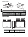
COMBUSTION--AIR PIPE FOR NON--DIRECT (1--PIPE) VENT APPLICATION (SIZES 040
THROUGH 120 ONLY)
FIELD-SUPPLIED
2-IN. DIAMETER
PVC 90° ELBOW
FIELD-SUPPLIED
2-IN. DIAMETER
PVC PIPE
COMBUSTION-AIR DISC
(FACTORY-SUPPLIED IN
LOOSE PARTS BAG)
A96211
Length of Straight Pipe Portion of Combustion Air Inlet Pipe Assembly --- In. (mm)
CASING WIDTH
A
17 1/2 (444.5)
8 1/2+/--- 1/2 (215.9 +/--- 12.7)
21 (533.4)
10 1/2 +/--- 1/2 (266.7 +/--- 12.7)
24 1/2 (622.3)
12 +/--- 1/2 (304.8 +/--- 12.7)
CONCENTRIC VENT (DIRECT VENT / 2--PIPE ONLY) (ALL MODEL SIZES)
B IN. DIA PVC
VENT/EXHAUST
F
E
C IN. DIA
13/16
11/2
D
A
B IN. DIA PVC
INTAKE/COMBUSTION AIR
Dimensions (In / mm)
KIT PART NO.
KGAVT0701CVT
KGAVT0801CVT
A*
33--- 3/8 (847.7)
38--- 7/8 (987.4)
B
2 (50.8)
3 (78.2)
C
3--- 1/2 (88.9)
4--- 1/2 (114.3)
D{
16--- 5/8 (422.3)
21--- 1/8 (536.6)
E
6--- 1/4 (158.8)
7--- 3/8 (189.3)
F
5--- 3/4 (146.1)
6--- 1/2 (165.1)
* Dimension A will change proportionally as dimension D is lengthened or shortened.
{ Dimension D may be lengthened to 60 in. (1524 mm) maximum. Dimension D may also be shortened by cutting the pipes provided in the kit to 12 in. (304.8
mm) minimum.
A97110
11
58MVB
A
CONDENSATE TRAP
FURNACE
DOOR
BLOWER SHELF
CONDENSATE
TRAP
CONDENSATE
TRAP (INSIDE)
FURNACE
DOOR
FURNACE
SIDE
4 7 8 124 mm
4
102 mm
FURNACE
SIDE
5 3 4 146 mm
5 3 4 146 mm
4
FIELD
DRAIN
CONN
58MVB
ALTERNATE DRAIN
TUBE LOCATION
26 1 4 667 mm
26 1 4
11 2
667 mm
38 mm
SIDE VIEW
CONDENSATE TRAP
DRAIN TUBE LOCATION
FIELD
DRAIN
CONN
FRONT VIEW
END VIEW
SLOT FOR SCREW
HORIZONTAL
APPLICATION
(OPTIONAL)
FRONT VIEW
HORIZONTAL
APPLICATIONS
DOWNFLOW AND ALTERNATE
EXTERNAL UPFLOW APPLICATIONS
UPFLOW APPLICATIONS
3 4 19 mm
1/4 OD
COLLECTOR BOX TO
TRAP RELIEF PORT
1 1 2 38 mm
1/2 OD
INDUCER HOUSING
DRAIN CONNECTION
19 mm 3 4
5/8 OD
COLLECTOR BOX
DRAIN CONNECTION
71 8
181 mm
SCREW HOLE FOR
UPFLOW OR DOWNFLOW APPLICATIONS
(OPTIONAL)
13 4 45 mm
WIRE TIE
GUIDES
(WHEN USED)
FRONT VIEW
78
22 mm
21 4
57 mm
1/2-IN.
PVC OR CPVC
SIDE VIEW
A93026
12
13
11⁄4"
1"
14 1⁄2"
TYP
1⁄2-IN.
26 15⁄16" TYP
23 1⁄4" TYP
SIDE INLET
SIDE INLET
DIA THERMOSTAT
ENTRY
22 11⁄16"
2-IN. VENT CONN
DIA
GAS CONN
1⁄2-IN.
2-IN. COMBUSTIONAIR CONN
22 5⁄16"
24 1⁄2"
1
26 ⁄4"
26 15⁄16"
17
E
INLET
OUTLET
D
11⁄16"
18 1⁄4"
⁄16"
TYP
9
DIMPLE LOCATORS
FOR HORIZONTAL
HANGING
CONDENSATE
DRAIN LOCATION
(UPFLOW)
30
1⁄2"
CONDENSATE DRAIN
TRAP LOCATION
(DOWNFLOW &
HORIZONTAL RIGHT)
OR ALTERNATE
1⁄2-IN. DIA GAS CONN
⁄ "
13 16
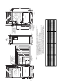
DIMENSIONS (IN / MM)
A
D
24---1/2 / 622.3
22---7/8 / 581.0
17---1/2 / 444.5
15---7/8 / 403.3
21 / 533.4
19---3/8 / 492.2
21 / 533.4
19---3/8 / 492.2
21 / 533.4
19---3/8 / 492.2
24---1/2 / 622.3
22---7/8 / 581.0
*These dimensions reflect the wider casing for the 96.6% AFUE furnace.
UNIT SIZE
040---14*
060---14
080---14
080---20
100---20
120---20
E
23 / 584.2
16 / 406.4
19---1/2 / 495.3
19---1/2 / 495.3
19---1/2 / 495.3
23 / 584.2
NOTES: 1. Minimum return-air openings at furnace, based on metal duct. If flex duct is used,
see flex duct manufacturer’s recommendations for equivalent diameters.
2. Minimum return-air opening at furnace:
a. For 800 CFM–16-in. round or 14 1/ 2 x 12-in. rectangle.
b. For 1200 CFM–20-in. round or 14 1/ 2 x 19 1/ 2-in. rectangle.
c. For 1600 CFM–22-in. round or 14 1/ 2 x 23 1/ 4-in. rectangle.
d. For airflow requirements above 1800 CFM, see Air Delivery table in Product Data
literature for specific use of single side inlets. The use of both side inlets, a
combination of 1 side and the bottom, or the bottom only will ensure adequate
return air openings for airflow requirements above 1800 CFM at 0.5 W.C. ESP.
11⁄16"
33 1⁄4"
TYP
32 5⁄8"
TYP
30 13⁄16"
29 11⁄16"
TYP
27 5⁄8"
27 9⁄16"
TYP
24 1⁄2"
5⁄16"
CONDENSATE
DRAIN LOCATION
(UPFLOW)
9
TYP
7⁄ "
16
CONDENSATE
DRAIN TRAP
LOCATION
(ALTERNATE
UPFLOW)
DIA
ACCESSORY
POWER ENTRY
7⁄8-IN.
DIA
POWER CONN
7⁄8-IN.
CONDENSATE DRAIN
TRAP LOCATION
(DOWNFLOW &
HORIZONTAL LEFT)
⁄ "
13 16
A
AIRFLOW
3 16
24 ⁄ "
BOTTOM INLET
22 1⁄4" TYP
SIDE INLET
22 11⁄16"
A05053
2-IN. VENT CONN
1⁄2-IN. DIA
THERMOSTAT ENTRY
7
⁄8-IN. DIA
POWER CONN
DIA
GAS CONN
1⁄2-IN.
2-IN. COMBUSTIONAIR CONN
OUTLET
19"
22 5⁄16"
26 1⁄4"
26 15⁄16"
28 1⁄2"
⁄ "
11 16
7⁄16"
1"
39 7⁄8"
5⁄16"
⁄16"
⁄8"
5
13
DOWNFLOW SUBBASE
LOCATING
TAB
1 1/4″ TYP
PLENUM
OPENING
B
A
D
1
2
3
4
LOCATING
TAB
C
FACTORY-SUPPLIED
FIELD-INSTALLED
INSULATION
4
58MVB
A97427
3
2
1
A88207
Assembled
Disassembled
DIMENSIONS (IN. / MM)
PLENUM OPENING*
FLOOR OPENING
HOLE NO. FOR
WIDTH
ADJUSTMENT
FURNACE
CASING WIDTH
FURNACE IN DOWNFLOW
APPLICATION
B
C
D
17--- 1/2 (444.5)
Furnace with or without Cased Coil
Assembly or Coil Box
15--- 1/8
(384.2)
19 (482.6)
16--- 3/4
(425.5)
20--- 3/8
(517.5)
3
21 (533.4)
Furnace with or without Cased Coil
Assembly or Coil Box
18--- 5/8
(396.4)
19 (482.6)
20--- 1/4
(514.4)
20--- 3/8
(517.5)
2
24--- 1/2 (622.3)
Furnace with or without Cased Coil
Assembly or Coil Box
22--- 1/8
(562.0)
19 (482.6)
23--- 3/4
(603.3)
20--- 3/8
(517.5)
1
A
*The plenum should be constructed 1/4 ---in. (6 mm) smaller in width and depth than the plenum dimensions shown above.
MEDIA FILTER CABINET
25 5/8"
23 5/8"
24 3/8"
Opening with Flanges Bent
23 3/8"
23 1/8"
Opening
B Opening
A
Duct Side
Furnace Side
23 3/4"
Centerline Screw Slots
5 3/4"
A05186
DIMENSIONS (IN. / MM)
MEDIA FILTER CABINET
A
B
SHIPPED WITH SIZES
16 (406.4)
17 (432.8)
16 (406.4)
040--- 08, 040--- 12, 060--- 08,
060--- 12, 080--- 12, 080--- 16
20 (508.0)
21 (533.4)
20 (508)
080--- 20, 100--- 16, 100--- 20
24 (609.6)
25 (635.0)
24 (609.6)
120--- 20, 140--- 20
14
ELECTRICAL DATA
UNIT SIZE
UNIT VOLTS --- HERTZ --- PHASE
OPERATING VOLTAGE RANGE
(Min --- Max)*
MAXIMUM UNIT AMPS
MINIMUM WIRE SIZE
MAXIMUM WIRE LENGTH --- Ft (M)‡
MAXIMUM FUSE OR CKT BKR
(Amps)**
TRANSFORMER (24v)
EXTERNAL CONTROL
Heating
POWER AVAILABLE
Cooling
040---14
060---14
080---14
080---20
115 --- 60 --- 1
100---20
120---20
104 --- 127
8.9
14
31 (9.4)
8.9
14
31 (9.4)
8.9
14
31 (9.4)
13.8
12
32 (9.8)
13.8
12
32 (9.8)
13.8
12
32 (9.8)
15
15
15
20
20
20
40va
25va
34va
58MVB
*Permissible limits of the voltage range at which the unit will operate satisfactorily.
‡Length shown is as measured one way along wire path between unit and service panel for maximum 2% voltage drop.
**Time ---delay type is recommended.
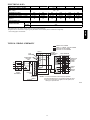
TYPICAL WIRING SCHEMATIC
FIELD 24-VOLT WIRING
FIELD 115-, 208/230-, 460-VOLT WIRING
FACTORY 24-VOLT WIRING
FACTORY 115-VOLT WIRING
NOTE 2
W
FIVE
WIRE
C
Y
R
G
1-STAGE
THERMOSTAT
TERMINALS
FIELD-SUPPLIED
FUSED DISCONNECT
THREE-WIRE
HEATINGONLY
BLK
WHT
BLK
W2
WHT
COM
208/230- OR
460-VOLT
THREE
PHASE
W/W1
GND
115-VOLT FIELDSUPPLIED
FUSED
DISCONNECT
JUNCTION
BOX
CONTROL
BOX
Y/Y2
NOTE 1
R
GND
CONDENSING
UNIT
G
24-VOLT
TERMINAL
BLOCK
FURNACE
208/230VOLT
SINGLE
PHASE
NOTES: 1. Connect Y/Y2-terminal as shown for proper operation.
2. Some thermostats require a "C" terminal connection as shown.
3. If any of the original wire, as supplied, must be replaced, use
same type or equivalent wire.
A95236
15
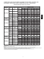
COMBUSTION--AIR AND VENT PIPING FOR DIRECT VENT/2--PIPE (ALL SIZES) AND
NON--DIRECT VENT/1--PIPE (SIZES 040 THROUGH 120 ONLY) APPLICATIONS
Maximum Allowable Pipe Length (Ft / M)
VARIABLE SPEED VENT SIZING TABLE
ALTITUDE
58MVB
0 to 2000 Ft /
0 to 610 M
ALTITUDE
2001 to 3000 Ft.
/
610 to 914 M
ALTITUDE
3001 to 4000 Ft /
914 to 1219 M
ALTITUDE
4001 to 5000 Ft‡
/
1219 to 1524 M
ALTITUDE
5001 to 6000 Ft‡
/
1524 to 1829 M
UNIT SIZE
(BTUH)
Termination
Type
40,000
2 Pipe or 2 ---In.
Concentric
60,000
2 Pipe or 2 ---In.
Concentric
80,000
2 Pipe or 2 ---In.
Concentric
100,000
2 Pipe or 2 ---In.
Concentric
120,000
2 Pipe or 3 ---In.
Concentric
UNIT SIZE
(BTUH)
Termination
Type
40,000
2 Pipe or 2 ---In.
Concentric
60,000
2 Pipe or 2 ---In.
Concentric
80,000
2 Pipe or 2 ---In.
Concentric
100,000
2 Pipe or 2 ---In.
Concentric
120,000
2 Pipe or 3 ---In.
Concentric
UNIT SIZE
(BTUH)
Termination
Type
40,000
2 Pipe or 2 ---In.
Concentric
60,000
2 Pipe or 2 ---In.
Concentric
80,000
2 Pipe or 2 ---In.
Concentric
100,000
2 Pipe or 2 ---In.
Concentric
120,000
2 Pipe or 3 ---In.
Concentric
UNIT SIZE
(BTUH)
Termination
Type
40,000
2 Pipe or 2 ---In.
Concentric
60,000
2 Pipe or 2 ---In.
Concentric
80,000
2 Pipe or 2 ---In.
Concentric
100,000
2 Pipe or 2 ---In.
Concentric
120,000
2 Pipe or 3 ---In.
Concentric
UNIT SIZE
(BTUH)
Termination
Type
40,000
2 Pipe or 2 ---In.
Concentric
60,000
2 Pipe or 2 ---In.
Concentric
80,000
2 Pipe or 2 ---In.
Concentric
100,000
2 Pipe or 2 ---In.
Concentric
120,000
2 Pipe or 3 ---In.
Concentric
Direct & Non--Direct Pipe
Dia. (IN.)*
1 ---1/2
2
1 ---1/2
2
1 ---1/2
2
2
2 ---1/2
2 ---1/2
3
3†
Direct & Non--Direct Pipe
Dia. (IN.)*
1 ---1/2
2
1 ---1/2
2
1 ---1/2
2
2
2 ---1/2
3
3†
Direct & Non--Direct Pipe
Dia. (IN.)*
1 ---1/2
2
1 ---1/2
2
1 ---1/2
2
2
2 ---1/2
3
3†
Direct & Non--Direct Pipe
Dia. (IN.)*
1 ---1/2
2
1 ---1/2
2
1 ---1/2
2
2
2 ---1/2
3†
NUMBER OF 90_ ELBOWS
1
2
3
4
5
6
50 / 15.2
70 / 21.3
50 / 15.2
70 / 21.3
30 / 9.14
70 / 21.3
45 / 13.7
70 / 21.3
10 / 3.0
35 / 10.7
70 / 21.3
45 / 13.7
70 / 21.3
45 / 13.7
70 / 21.3
25 / 7.6
70 / 21.3
40 / 12.9
70 / 21.3
NA
30 / 9.1
70 / 21.3
40 / 12.9
70 / 21.3
40 / 12.9
70 / 21.3
20 / 6.1
70 / 21.3
35 / 10.7
70 / 21.3
NA
15 / 4.8
70 / 21.3
35 / 10.7
70 / 21.3
35 / 10.7
70 / 21.3
15 / 4.6
70 / 21.3
30 / 9.1
70 / 21.3
NA
NA
70 / 21.3
30 / 9.1
70 / 21.3
30 / 9.1
70 / 21.3
10 / 3.0
70 / 21.3
25 / 7.6
70 / 21.3
NA
NA
70 / 21.3
25 / 7.6
70 / 21.3
25 / 7.6
70 / 21.3
5 / 1.5
70 / 21.3
20 / 6.1
70 / 21.3
NA
NA
70 / 21.3
NUMBER OF 90_ ELBOWS
1
2
3
4
5
6
45 / 13.7
70 / 21.3
45 / 13.7
70 / 21.3
26 / 7.9
70 / 21.3
40 / 12.2
70 / 21.3
31 / 9.4
63 / 19.2
40 / 12.9
70 / 21.3
40 / 12.9
70 / 21.3
21 / 6.4
70 / 21.3
35 / 10.7
70 / 21.3
26 / 7.9
62 / 18.9
35 / 10.7
70 / 21.3
35 / 10.7
70 / 21.3
16 / 4.9
70 / 21.3
30 / 9.1
70 / 21.3
12 / 3.7
62 / 18.9
30 / 9.14
70 / 21.3
30 / 9.14
70 / 21.3
11 / 3.4
70 / 21.3
25 / 7.6
70 / 21.3
NA
61 / 18.6
25 / 7.6
70 / 21.3
25 / 7.6
70 / 21.3
6 / 1.8
70 / 21.3
20 / 6.1
70 / 21.3
NA
61 / 18.6
20 / 6.1
70 / 21.3
20 / 6.1
70 / 21.3
NA
70 / 21.3
15 / 4.6
70 / 21.3
NA
61 / 18.6
1
2
3
4
5
6
42 / 12.8
70 / 21.3
42 / 12.8
70 / 21.3
25 / 7.6
70 / 21.3
38 / 11.6
70 / 21.3
29 / 8.8
59 / 18.0
37 / 11.2
70 / 21.3
37 / 11.2
70 / 21.3
20 / 6.1
70 / 21.3
33 / 10.1
70 / 21.3
24 / 7.3
59 / 18.0
32 / 9.8
70 / 21.3
32 / 9.8
70 / 21.3
15 / 4.6
70 / 21.3
28 / 8.5
70 / 21.3
10 / 3.0
58 / 17.8
27 / 8.2
70 / 21.3
27 / 8.2
70 / 21.3
10 / 3.0
70 / 21.3
23 / 7.0
70 / 21.3
NA
57 / 17.4
22 / 6.7
70 / 21.3
22 / 6.7
70 / 21.3
5 / 1.5
70 / 21.3
18 / 5.5
70 / 21.3
NA
57 / 17.4
17 / 5.2
NUMBER OF 90_ ELBOWS
70 / 21.3
17 / 5.2
70 / 21.3
NA
70 / 21.3
13 / 4.0
70 / 21.3
NA
56 / 17.0
NUMBER OF 90_ ELBOWS
1
2
3
4
5
6
40 / 12.2
70 / 21.3
40 / 12.2
70 / 21.3
23 / 7.0
70 / 21.3
36 / 11.0
70 / 21.3
35 / 10.7
70 / 21.3
35 / 10.7
70 / 21.3
18 / 5.5
70 / 21.3
31 / 9.4
70 / 21.3
30 / 9.1
70 / 21.3
30 / 9.1
70 / 21.3
13 / 4.0
70 / 21.3
26 / 7.9
70 / 21.3
25 / 7.6
70 / 21.3
25 / 7.6
70 / 21.3
8 / 2.4
70 / 21.3
21 / 6.4
70 / 21.3
20 / 6.1
70 / 21.3
20 / 6.1
70 / 21.3
NA
70 / 21.3
16 / 4.8
70 / 21.3
15 / 9.6
70 / 21.3
15 / 9.6
70 / 21.3
NA
68 / 20.7
11 / 3.4
70 / 21.3
56 / 17.1
55 / 16.8
54 / 16.5
53 / 6.2
52 / 15.8
52 / 15.8
Direct & Non--Direct Pipe
Dia. (IN.)*
1 ---1/2
2
1 ---1/2
2
1 ---1/2
2
2
2 ---1/2
1
2
3
4
5
6
37 / 11.3
70 / 21.3
37 / 11.3
70 / 21.3
22 / 6.7
70 / 21.3
33 / 10
70 / 21.3
32 / 9.8
70 / 21.3
32 / 9.8
70 / 21.3
17 / 5.2
70 / 21.3
28 / 8.5
70 / 21.3
27 / 8.2
70 / 21.3
27 / 8.2
70 / 21.3
12 / 3.7
70 / 21.3
23 / 7.0
70 / 21.3
22 / 6.7
70 / 21.3
22 / 6.7
70 / 21.3
7 / 2.1
70 / 21.3
18 / 5.5
70 / 21.3
17 / 5.2
70 / 21.3
17 / 5.2
70 / 21.3
NA
68 / 20.7
13 / 4.0
70 / 21.3
12 / 3.7
70 / 21.3
12 / 3.7
70 / 21.3
NA
63 / 19.2
8 / 2.4
70 / 21.3
3†
53 / 16.2
52 / 15.8
50 / 15.2
49 / 14.9
48 / 14.6
47 / 14.3
NUMBER OF 90_ ELBOWS
*See notes on next page.
16
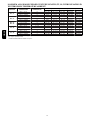
COMBUSTION--AIR AND VENT PIPING FOR DIRECT VENT/2--PIPE (ALL SIZES) AND
NON--DIRECT VENT/1--PIPE (SIZES 040 THROUGH 120 ONLY) APPLICATIONS
Maximum Allowable Pipe Length (Ft / M) (Continued)
Variable Speed Vent Sizing Table
6001 to 7000 Ft‡
/
1829 to 2134 M
ALTITUDE
7001 to 8000 Ft‡
/
2134 to 2438 M
ALTITUDE
8001 to 9000 Ft‡
/
2438 to 2743 M
ALTITUDE
9001 to 10000
Ft.‡ /
2743 to 3048 M
NUMBER OF 90_ ELBOWS
1
2
3
4
5
6
40,000
2 Pipe or 2 ---In.
Concentric
35 / 10.7
70 / 21.3
30 / 9.1
70 / 21.3
25 / 7.6
68 / 20.7
20 / 6.1
67 / 20.4
10 / 3.0
64 / 19.5
60,000
2 Pipe or 2 ---In.
Concentric
1 ---1/2
2
35 / 10.7
70 / 21.3
30 / 9.1
70 / 21.3
25 / 7.6
68 / 20.7
20 / 6.1
67 / 20.4
80,000
2 Pipe or 2 ---In.
Concentric
100,000
2 Pipe or 2 ---In.
Concentric
1 ---1/2
2
2
2 ---1/2
20 / 6.1
70 / 21.3
31 / 9.4
70 / 21.3
15 / 4.6
70 / 21.3
26 / 7.9
70 / 21.3
10 / 3.0
68 / 20.7
21 / 6.4
68 / 20.7
5 / 1.5
67 / 20.4
16 / 4.9
67 / 20.4
15 / 4.6
66 /
20.11
15 / 4.6
66 /
20.11
NA
62 / 18.9
11 / 3.4
66 / 20.1
120,000
2 Pipe or 3 ---In.
Concentric
3†
49 / 14.9
48 / 14.6
47 / 14.3
45 / 13.7
44 / 13.4
43 / 13.1
UNIT SIZE
(BTUH)
UNIT SIZE
(BTUH)
Termination
Type
Termination
Type
40,000
2 Pipe or 2 ---In.
Concentric
60,000
2 Pipe or 2 ---In.
Concentric
80,000
2 Pipe or 2 ---In.
Concentric
100,000
2 Pipe or 2 ---In.
Concentric
120,000
2 Pipe or 3 ---In.
Concentric
UNIT SIZE
(BTUH)
Termination
Type
40,000
2 Pipe or 2 ---In.
Concentric
60,000
2 Pipe or 2 ---In.
Concentric
80,000
2 Pipe or 2 ---In.
Concentric
100,000
2 Pipe or 2 ---In.
Concentric
120,000
2 Pipe or 3 ---In.
Concentric
UNIT SIZE
(BTUH)
Termination
Type
40,000
2 Pipe or 2 ---In.
Concentric
60,000
2 Pipe or 2 ---In.
Concentric
80,000
2 Pipe or 2 ---In.
Concentric
100,000
2 Pipe or 2 ---In.
Concentric
10 / 3.0
64 / 19.5
NA
57 / 17.4
6 / 1.8
64 / 19.5
Direct & Non--Direct Pipe
Dia. (IN.)*
1 ---1/2
2
1 ---1/2
2
1 ---1/2
2
2
2 ---1/2
1
2
3
4
5
6
32 / 9.8
66 /20.1
32 / 9.8
66 /20.1
18 / 5.5
66 / 20.1
29 / 8.8
66 / 20.1
27 / 8.2
65 / 19.8
27 / 8.2
65 / 19.8
13 / 4.0
65 / 19.8
24 / 7.3
65 / 19.8
22 / 6.7
63 / 19.2
22 / 6.7
63 / 19.2
8 / 2.4
63 / 19.2
19 / 5.8
63 / 19.2
17 / 5.2
62 / 18.9
17 / 5.2
62 / 18.9
NA
62 / 18.9
14 / 4.3
62 / 18.9
12 / 3.7
60 / 18.3
12 / 3.7
60 / 18.3
NA
57 / 17.4
9 / 2.7
60 / 18.3
7 / 2.1
59 / 18.0
7 / 2.1
59 / 18.0
NA
52 / 15.8
NA
59 / 18
3†
46 / 14.0
44 / 13.4
43 / 13.1
41 / 12.5
40 / 12.2
38 / 11.6
NUMBER OF 90_ ELBOWS
Direct & Non--Direct Pipe
Dia. (IN.)*
1 ---1/2
2
1 ---1/2
2
1 ---1/2
2
2
2 ---1/2
1
2
3
4
5
6
30 / 9.1
62 / 18.9
30 / 9.1
62 / 18.9
17 / 5.2
62 / 18.9
27 / 8.2
62 / 18.9
25 / 7.6
60 / 17.8
25 / 7.6
60 / 17.8
12 / 3.1
60 / 18.3
22 / 6.7
60 / 18.3
20 / 6.1
58 / 17.7
20 / 6.1
58 / 17.7
7 / 2.1
58 / 17.7
17 / 5.2
58 / 17.7
15 / 4.6
56 / 17.1
15 / 4.6
56 / 17.1
NA
56 / 17.1
12 / 3.7
56 / 17.1
10 / 3.0
55 / 16.8
10 / 3.0
55 / 16.8
NA
51 / 15.5
7 / 2.1
55 / 16.8
5 / 1.5
53 / 16.2
5 / 1.5
53 / 16.2
NA
46 / 14.0
NA
53 / 16.2
3†
43 / 13.1
41 / 12.5
39 /11.9
37 / 11.3
35 / 10.7
34 / 10.4
1
2
3
4
5
6
27 / 8.2
57 / 17.4
27 / 8.2
57 / 17.4
15 / 4.6
57 / 17.4
24 / 7.3
57 / 17.4
22 / 6.7
55 / 16.8
22 / 6.7
55 / 16.8
10 / 3.0
55 / 16.8
19 / 5.8
55 / 16.8
17 / 5.2
53 / 16.2
17 / 5.2
53 / 16.2
5 / 1.5
53 / 16.2
14 / 4.3
53 / 16.2
12 / 3.7
51 / 15.5
12 / 3.7
51 / 15.5
NA
51 / 15.5
9 / 2.7
51 / 15.5
7 / 2.1
49 / 14.9
7 / 2.1
49 / 14.9
NA
46 / 14.0
NA
49 / 14.9
NA
47 / 14.3
NA
47 / 14.3
NA
41 / 12.5
NA
47 / 14.3
Direct & Non--Direct Pipe
Dia. (IN.)*
1 ---1/2
2
1 ---1/2
2
1 ---1/2
2
2
2 ---1/2
58MVB
ALTITUDE
Direct & Non--Direct Pipe
Dia. (IN.)*
1 ---1/2
2
NUMBER OF 90_ ELBOWS
NUMBER OF 90_ ELBOWS
2 Pipe or 3 ---In.
3†
39 / 11.9
37 / 11.3
35 / 10.7
33 / 10.1
31 / 9.5
29 / 8.8
Concentric
* Disk usage ---Unless otherwise stated, use perforated disk assembly (factory ---supplied in loose parts bag).
{ Wide radius elbow.
} Vent sizing for Canadian installations over 4500 ft (1370m) above sea level are subject to acceptance by the local authorities having jurisdiction.
NA---Not Allowed; pressure switch will not make.
NOTES:
1. Do not use pipe size greater than those specified in table or incomplete combustion, flame disturbance, or flame sense lockout may occur.
2. Size both the combustion ---air and vent pipe independently, determine the smallest diameter allowed by the table for each pipe, then use the larger diameter for both pipes.
3. Assume two 45_ elbows equal one 90_ elbow. Long radius elbows are desirable and may be required in some cases.
4. Elbows and pipe sections within the furnace casing and at the vent termination should not be included in vent length or elbow count.
5. The minimum pipe length is 5 ft (1.5 M) for all applications.
120,000
17
MAXIMUM ALLOWABLE EXPOSED VENT PIPE LENGTH (FT / M) WITH INSULATION IN
WINTER DESIGN TEMPERATURE AMBIENT*
UNIT SIZE
040---14
060---14
080---14
080---20
58MVB
100---20
120---20
WINTER DESIGN
TEMPERATURE
20_F / --- 6.7_C
0_F / --- 17.8_C
--- 20_F / --- 28.9_C
20_F / --- 6.7_C
0_F / --- 17.8_C
--- 20_F / --- 28.9_C
20_F / --- 6.7_C
0_F / --- 17.8_C
--- 20_F / --- 28.9_C
20_F / --- 6.7_C
0_F / --- 17.8_C
--- 20_F / --- 28.9_C
20_F / --- 6.7_C
0_F / --- 17.8_C
--- 20_F / --- 28.9_C
MAXIMUM PIPE
DIAMETER (IN.)
2
2
2
2
2
2
2
2
2
2--- 1/2
2--- 1/2
2--- 1/2
3
3
3
0
21 / 6.4
10 / 3.0
5 / 1.5
30 / 9.1
16 / 4.9
9 / 2.7
37 / 11.2
20 / 6.1
11 / 3.4
41 / 12.5
21 / 6.4
11 / 3.4
49 / 14.9
26 / 7.9
15 / 4.6
INSULATION THICKNESS†
3/8
1/2
3/4
37 / 11.3
42 / 12.8
50 / 15.2
22 / 6.7
25 / 7.6
30 / 9.1
14 / 4.3
17 / 5.2
21 / 6.4
55 / 16.8
61 / 18.6
70 / 21.3
33 / 10.1
38 / 11.6
46 / 14.0
23 / 7.0
26 / 7.9
33 / 10.1
65 / 19.8
70 / 21.4
70 / 21.3
39 / 11.9
45 / 13.7
55 / 16.8
27 / 8.3
31 / 9.4
39 / 11.9
70 / 21.3
70 / 21.3
70 / 21.3
42 / 12.8
48 / 14.6
59 / 18.0
28 / 8.5
33 / 10.1
41 / 12.5
70 / 21.3
70 / 21.3
70 / 21.3
51 / 15.5
58 / 17.7
70 / 21.3
35 / 10.7
40 / 12.2
50 / 15.2
1
57 / 17.4
35 / 10.7
25 / 7.6
70 / 21.3
53 / 16.2
38 / 11.6
70 / 21.3
63 / 19.2
45 / 13.7
70 / 21.3
68 / 20.7
49 / 14.9
70 / 21.3
70 /21.3
59 / 18.0
* Pipe length (ft/m) specified for maximum pipe lengths located in unconditioned spaces. Pipes located in unconditioned space cannot exceed total allowable
pipe length as specified in Table.
†Insulation thickness based on R value of 3.5 per in.
18
58MVB
CLEARANCE TO COMBUSTIBLES
335122-201 REV. B LIT TOP
A08435
19
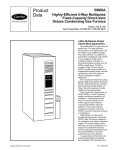
TYPICAL INSTALLATIONS
COMBUSTION AIR PIPE
(DIRECT VENT/2-PIPE APPLICATION)
OUTDOOR UNIT
VENT PIPE
A/C COIL
58MVB
HUMIDIFIER
COMBUSTION
AIR INLET
(NON-DIRECT
1-PIPE APPLICATION)
GAS-FIRED
WATER HEATER
ELECTRONIC
AIR CLEANER
FRONT OF
FURNACE
AIRFLOW
A05064
Upflow Application
ELECTRONIC
AIR CLEANER
VENT
COMBUSTION AIR
INLET (NON-DIRECT
VENT/ 1-PIPE APPLICATION
COMBUSTION
AIR (DIRECT VENT/
2 PIPE APPLICATION
HUMIDIFIER
OUTDOOR
UNIT
A/C COIL
AIRFLOW
FRONT OF
FURNACE
A05065
Downflow Application
20
TYPICAL INSTALLATIONS (CONTINUED)
COMBUSTION-AIR INLET
(NON-DIRECT VENT/1-PIPE APPLICATION)
COMBUSTION–AIR PIPE
DIRECT VENT/2-PIPE APPLICATION)
58MVB
VENT PIPE
ELECTRONIC
AIR CLEANER
FRONT OF FURNACE
FURNACE
CONDENSATE
DRAIN
REFRIGERATION
PIPING
AIR CONDITIONING
COIL
AIRFLOW
A05066
Attic --- Horizontal Application
COMBUSTION– AIR PIPE
(DIRECT VENT/2-PIPE
APPLICATION)
COMBUSTION - AIR INLET
(NON-DIRECT VENT/
1-PIPE APPLICATION)
VENT
PIPE
REFRIGERATION
PIPING
AIR CONDITIONING
COIL
ELECTRONIC
AIR CLEANER
AIRFLOW
FURNACE CONDENSATE
DRAIN
FRONT OF
FURNACE
Crawlspace --- Horizontal Application
21
A05067
GUIDE SPECIFICATIONS
General
Infinityt 96
Two--Stage/Variable Speed Gas Furnace
System Description
Furnish a ______________________ 4--way multipoise gas--fired
condensing furnace for use with natural gas or propane (factory-authorized conversion kit required for propane); furnish cold air
return plenum; furnish external media cabinet for use with
accessory media filter or standard filter.
58MVB
Quality Assurance
Unit will be designed, tested and constructed to the current ANSI Z
21.47/CSA 2.3 design standard for gas--fired central furnaces.
Unit will be third party certified by CSA to the current ANSI Z
21.47/CSA 2.3 design standard for gas--fired central furnaces. Unit
will carry the CSA Blue StarR and Blue FlameR
labels. Unit
efficiency testing will be performed per the current DOE test
procedure as listed in the Federal Register.
Unit will be certified for capacity and efficiency and listed in the
latest GAMA Consumer’s Directory of Certified Efficiency
Ratings.
Unit will carry the current Federal Trade Commission Energy
Guide efficiency label.
Delivery, Storage, and Handling
Unit will be shipped as single package only and is stored and
handled per unit manufacturer’s recommendations.
Warranty (for inclusion by specifying engineer)
U.S. and Canada only. Warranty certificate available upon request.
Equipment
Blower Wheel and ECM Blower Motor
Galvanized blower wheel shall be centrifugal type, statically and
dynamically balanced. Blower motor of ECM type shall be
permanently lubricated with sealed ball bearings, of _______hp,
and have infinitely variable speed from 250--1300 RPM operating
only when 24--VAC motor inputs are provided. Blower motor shall
be direct drive and soft mounted to the blower scroll to reduce
vibration transmission.
Filters
Furnace shall have reusable--type filters. Filter shall be ______ in.
(mm) (X) ________ in. (mm). An accessory highly efficient
Media Filter is available as an option. _____________ Media
Filter.
Casing
Casing shall be of .030 in. thickness minimum, pre--painted
galvanized steel.
ECM Inducer Motor
ECM Inducer motor shall be variable speed design, soft mounted
to assembly to reduce vibration transmission.
Primary Heat Exchangers
Primary heat exchangers shall be 3--Pass 20 gauge corrosion-resistant aluminized steel of fold--and--crimp sectional design and
applied operating under negative pressure.
Secondary Heat Exchangers
Secondary heat exchangers shall be of a flow--through design
having a patented interior laminate coating of polypropylene for
greater corrosion resistance with fold--and--crimp design and
applied operating under negative pressure.
Controls
Controls shall include a micro--processor--based integrated
electronic control board with at least 16 service troubleshooting
codes displayed via diagnostic flashing LED light on the control, a
self--test feature that checks all major functions of the furnace, and
a replaceable automotive--type circuit protection fuse. Multiple
operational settings available, including separate blower speeds for
low heat, medium heat, high heat, low cooling, high cooling and
continuous fan. Continuous fan speed may be adjusted from the
thermostat. Cooling airflow will be selectable between 350 or 400
CFM per ton of air conditioning. Features will also include
temporary reduced airflow in the cooling mode for improved
dehumidification when an Infinity Control or Thermidistat is
selected as the thermostat.
Operating Characteristics
Heating capacity shall be _________________ Btuh input;
______________ Btuh output capacity.
Fuel Gas Efficiency shall be 92 to 96.6% AFUE.
Air delivery shall be ________________ cfm minimum at 0.50 in.
wc. external static pressure.
Dimensions shall be: depth_________in. (mm); width
__________in. (mm); height___________in. (mm) (casing only).
Height shall be
_________in. (mm) with A/C coil and _________________in.
(mm) overall with plenum.
Electrical Requirements
Electrical supply shall be 115 volts, 60 Hz, single--phase (nominal).
Minimum wire size shall be ________AWG; maximum fuse size
of HACR--type designated circuit breaker shall be _________
amps.
Special Features
Refer to section of the product data identifying accessories and
descriptions for specific features and available enhancements.
Copyright 2010 Carrier Corp. S 7310 W. Morris St. S Indianapolis, IN 46231
Printed in U.S.A.
Edition Date: 09/10
Manufacturer reserves the right to change, at any time, specifications and designs without notice and without obligations.
22
Catalog No: 58MVB---3PD
Replaces: 58MVB--- 2PD