1
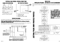
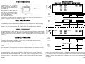
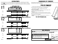
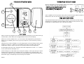
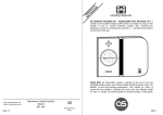
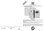
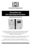
The ThermoPlus has two preset temperature levels, these are known as ‘Warm’, higher level
temperature(21oC) and ‘Cool’, lower or set back temperature(15oC). The preset temperatures
have been selected to give a comfortable, safe, yet efficient comfort level in the home.
In certain installations it may be necessary to adjust either the ‘Warm’ and / or ‘Cool’
temperatures to meet the specific needs of the user. This can be achieved by following the simple steps below;
IN
ST TH
AL ER
LA M
TIO OP
N LUS
IN P
ST RT
RU 1
CT
IO
NS
WARM AND COOL TEMPERATURE ADJUSTMENTS
The Horstmann ThermoPlus PRT1 - Programmable Room Thermostat Offers a
number of pre-installed heating profiles which are simply set-up by the
installer to provide maximum comfort to the user. Once installed, user
operations are kept to a minimum by using the +/ - and Warm/Cool buttons
on the front of the unit.
Please ensure that the installation checklist, located within the product
packaging, is completed before handing over the installation.
PLEASE NOTE: It is not necessary to enter the installer mode to adjust the temperature settings.
GENERAL INFORMATION
Before handing over the installation to the user, always ensure that the system responds
correctly on all control programmes and that other electrically operated equipment and
controls are correctly adjusted.
EXPLAIN HOW TO OPERATE THE CONTROLS AND HAND OVER THE USERS OPERATING
INSTRUCTIONS TO THE USER.
SPECIFICATION THERMOPLUS PRT1
Contact type: Micro dis-connection
(Voltage Free)
Contact rating: 3(1)Amps 230-240V AC
Power supply: 230-240V AC 50Hz
Operating Temperature range: 0oC to 40oC
Temperature Control Range: 5oC to 30oC
Standby Temperature: 5oC to 10oC
Double insulated.
Dirt protection: Normal situations.
Enclosure protection: IP30
Purpose of control: Electronic thermostat
Email: [email protected]
Website: www.horstmann.co.uk
Battery Type: Lithium
Case material: Thermoplastic, flame retardant
Dimensions: 120mm x 90mm x 32mm
Display: Liquid crystal
Clock: 24 hour
Display time adjustment: 1 Minute steps
Switched time adjustment: 15 Minute steps
Programme selection: Auto, Standby
Operating periods per day (Warm): 3
Override: Instant Warm/Cool
Backplate: Industry Standard Backplate
Horstmann Controls Limited
Bristol
BS4 1UP
LEAFLET No P82324
ISSUE 1
PLEASE NOTE: The ThermoPlus contains a selection of five pre-set profile options, one of these
must be set by the Installer. It is vital that care is taken to ensure a profile is selected
that suits the lifestyle of the householder concerned.
TABLE OF CONTENTS
INTRODUCTION
ELECTRICAL CONNECTIONS - INTERNAL AND EXTERNAL
STANDARD WIRING DIAGRAM
SPECIFIED BOILER CONNECTIONS
FITTING THE BACKPLATE
ELECTRICAL CONNECTIONS
FITTING TO BACKPLATE
RESET PROCEDURE
PAGE 1
PAGE 2
PAGE 2
PAGE 3
PAGE 4
PAGE 4
PAGE 5
PAGE 5
BASIC OPERATION
ACCESSING THE INSTALLER MODE
TIME AND DATE CHECK
PRE-SET PROFILES
SETTING USER PROFILES 1 - 5
SETTING YOUR OWN PROFILE
TEMPERATURE ADJUSTMENT
GENERAL INFORMATION
PRODUCT SPECIFICATION
PAGE 6
PAGE 7
PAGE 7
PAGE 8/9
PAGE 10
PAGE 11
PAGE 12
PAGE 12
PAGE 12
PAGE 1
INTERNAL WIRING CONNECTIONS
PROFILE SIX
INSTALLER DEFINABLE - 24 HOUR OR 7 DAY PROGRAMMING
REAR VIEW OF THE THERMOPLUS
1
- The ThermoPlus has Voltage Free
contacts.
- A link L - 2 is required for mains
Voltage applications.
- The ThermoPlus PRT1 is mains
operated, not battery powered.
3
2
1 - CONNECTOR PINS
2 - CAPACITY LABEL
3 - PRODUCTION DATE LABEL
WIRING DIAGRAMS
An example circuit diagram for a typical combination boiler installation is shown below. This
diagram is schematic and should be used as a guide only.
Please ensure that all installations comply with the current IEE regulations and the boiler
manufacturers installation instructions.
For reasons of space and clarity not every connection has been included and the diagram has
been simplified, for instance some Earth connections have been omitted.
Profile six will allow the installer to set up a profile to the exact requirements of the user. By
using the flow chart below you can adjust the Warm/Cool timing periods on each day of the
week.
SETTING YOUR OWN PROFILE PROFILE
INTERNAL AND EXTERNAL WIRING CONNECTIONS
COPY FEATURE
The copy feature can be used to
apply changes made from one
days programming to the next.
This is achieved by pressing the
down arrow button when ‘SET’
is displayed on the screen.
‘SET’ is displayed after the last
cool period is confirmed on
each day.
Typical combination boiler installation
PAGE 2
PAGE 11
SPECIFIED BOILER CONNECTIONS
SETTING USER PROFILES - ONE TO FIVE
The ThermoPlus contains a selection of five pre-set profile options, one of these must be set
by the Installer. It is vital that care is taken to ensure a profile is selected that suits the
lifestyle of the householder concerned. The flow chart below is designed to easily guide
you through the process of setting the required profile.
VAILLANT ECOMAX 824/2E
VAILLANT TURBOMAX PLUS 824/2E
(Remove link from terminals 3/4.)
(Remove link from terminals 3/4.)
Profiles one to five are detailed on page 8 and 9.
BOILER TERMINAL
PLEASE NOTE: If none of the provided profiles meet the users requirements it is possible to set
a user defiled profile, full details are given on page 11.
THERMOPLUS TERMINAL
3
4
2
4
BOILER TERMINAL
THERMOPLUS TERMINAL
3
4
2
4
RAVENHEAT CSI 85
RAVENHEAT LS 80
(Remove link from
room thermostat terminals)
(Remove link from
room thermostat terminals)
BOILER TERMINAL
THERMOPLUS TERMINAL
Out
Switch
2
4
BOILER TERMINAL
THERMOPLUS TERMINAL
Out
Switch
2
4
IDEAL HE24
IDEAL MINI C24
(Remove link from terminals L1/L2.)
(Remove link from terminals 1/3.)
BOILER TERMINAL
L1
L2
THERMOPLUS TERMINAL
2
4
BOILER TERMINAL
3
1
THERMOPLUS TERMINAL
2
4
INSTALLATION AND CONNECTION OF THE THERMOPLUS PRT1 SHOULD ONLY BE CARRIED OUT
BY A SUITABLY QUALIFIED PERSON. ALWAYS CONSULT THE SPECIFIC BOILER MANUFACTURERS
INSTALLATION INSTRUCTIONS BEFORE COMMENCING THE INSTALLATION .
Profiles one to five have fixed programmes, they can be reviewed by
pressing the set button once the selection process detailed above have
been completed. To set a custom profile please refer to the instructions
on page 11.
PAGE 10
WARNING : ISOLATE MAINS SUPPLY BEFORE COMMENCING INSTALLATION
PAGE 3
FITTING THE BACKPLATE
PROFILE
Once the Backplate has been
removed from the packaging
please ensure the ThermoPlus is
re-sealed to prevent damage from
dust, debris etc.
The Backplate should be fitted with
the wiring terminals located at the
top and in a position which allows
a total clearance of at least 50mm
around the thermostat.
The ThermoPlus should be
mounted on an internal wall approximately 1.5 metres from floor level and should be in a
position away from draughts, direct heat and sunlight.
PROFILES FOUR AND FIVE
5 DAY / 2 DAY - DIFFERENT WEEKDAY / WEEKEND PROFILE
Time
Profile
2
3
4
5
6
STATUS
WARM
COOL
WARM
COOL
WARM
COOL
7
SAT/SUN
START
07:00
22:00
STATUS
WARM
COOL
TIME PROFILE
8 9 10 11 12 13 14 15 16 17 18 19 20 21 22 23 00
SAT / SUN
TEMPERATURE PROFILE
MON-FRI
Warm
Cool
Offer the plate to the wall in the position where the ThermoPlus is to be mounted,
remembering that the Backplate fits to the left hand end of the thermostat. Mark the fixing
positions through the slots in the Backplate, drill and plug the wall, then secure the plate in
position. The slots in the Backplate will compensate for any misalignment of the fixings.
SAT / SUN
Warm
Cool
PROFILE
WIRING BOX MOUNTING
ELECTRICAL CONNECTIONS
1
START
06:00
08:00
11:30
13:30
17:00
22:30
MON-FRI
DIRECT WALL MOUNTING
The Backplate may be fitted directly on to a single gang steel flush wiring box complying with
BS4662, using two M3.5 screws. ThermoPlus thermostats are suitable for mounting on a flat
surface only, they must not be positioned on a surface mounted wall box or on unearthed metal
surfaces.
4
PROFILE FOUR
MON - FRI
5
Time
Profile
All necessary electrical connections should now be made. Flush wiring can enter from the rear
through the aperture in the Backplate. Surface wiring can only enter from beneath the
ThermoPlus and must be securely clamped.
MON-FRI
The mains supply terminals are intended to be connected to the supply by means of fixed
wiring.
MON-FRI
PROFILE FIVE
MON - FRI
1
2
START
06:00
08:00
17:00
22:30
3
4
5
6
STATUS
WARM
COOL
WARM
COOL
7
SAT/SUN
START
07:00
22:00
STATUS
WARM
COOL
TIME PROFILE
8 9 10 11 12 13 14 15 16 17 18 19 20 21 22 23 00
SAT / SUN
TEMPERATURE PROFILE
The ThermoPlus is mains powered and requires a 3 Amp fused spur. The recommended cable
sizes are 1.0mm2 or 1.5mm2.
The ThermoPlus is double insulated and does not require an Earth connection, an Earth
connection block is provided on the Backplate for terminating any cable Earth conductors.
Earth continuity must be maintained and all bare Earth conductors must be sleeved. Ensure
that no conductors are left protruding outside the central space enclosed by the Backplate.
PAGE 4
Warm
Cool
SAT / SUN
Warm
Cool
Profiles one to five have fixed periods, no alteration to the Warm/Cool times can be made,
if it is necessary make any alterations then profile six must be used. Profile six will allow the
installer to set up a profile to the exact requirements of the user. Please refer to the flowchart
on page 11.
PAGE 9
HEATING PROFILES
PROFILE
The ThermoPlus has six heating profiles, five are fixed and one adjustable by the installer.
ONE’ has been set as the default and is detailed below. During installation a heating
Profile ‘O
profile should be set to best match the users requirements, illustrations of the pre-set profiles
are shown below.
1
Time
PROFILES ONE TO THREE
24 HOUR - SAME PROFILE EACH DAY
PROFILE ONE - DEFAULT
EVERY DAY
1
2
3
4
5
6
7
START
06:00
22:00
STATUS
WARM
COOL
TIME PROFILE
8 9 10 11 12 13 14 15 16 17 18 19 20 21 22 23 00
Profile
TEMPERATURE PROFILE
PROFILE
Warm
Cool
2
Time
PROFILE TWO
EVERY DAY
1
2
3
4
5
6
7
START
06:00
08:00
17:00
22:30
COMMISSIONING THE THERMOSTAT
Ensure all dust and debris has been cleared away from the work area before removing the
ThermoPlus PRT1 from its packaging.
FITTING THE THERMOSTAT
- If surface wiring has been used, remove the knockout/insert
from the bottom of the thermostat to accommodate it.
- Loosen the two ‘captive’ retaining screws on the
bottom of the Backplate.
- Fit the thermostat to the Backplate, ensure the lugs on the
Backplate engage with the slots on the
thermostat.
- Swing the bottom of the thermostat into position ensuring
that the connection pins on the back of the unit locate into the
terminal slots in the backplate.
- Tighten the two ‘captive’ retaining screws to fix the unit
securely.
Then switch ON the mains supply.
STATUS
WARM
COOL
WARM
COOL
END VIEW OF THE
THERMOPLUS
TIME PROFILE
8 9 10 11 12 13 14 15 16 17 18 19 20 21 22 23 00
Profile
TEMPERATURE PROFILE
PROFILE
Warm
Cool
PROFILE THREE
EVERY DAY
3
Time
1
2
3
4
5
6
7
START
06:00
08:00
11:30
13:30
17:00
22:30
TIME PROFILE
8 9 10 11 12 13 14 15 16 17 18 19 20 21 22 23 00
Profile
TEMPERATURE PROFILE
Warm
Cool
PAGE 8
STATUS
WARM
COOL
WARM
COOL
WARM
COOL
RESET PROCEDURE
PLEASE NOTE; Using this procedure will restore the ThermoPlus to the original factory
programme settings, the time setting will also default to 1st January 2005.
RESETTING THE THERMOPLUS PRT1
- On the ThermoPlus PRT1 press the ‘UP’ and
‘DOWN’ arrow buttons together:
- Then release the buttons and the thermostat will
return to preset factory settings.
TO RESET PRESS
PAGE 5
INSTALLER OPERATING GUIDE
THERMOPLUS INSTALLER MODE
6
Once the ThermoPlus has been installed, please press buttons 4 and 8 Simultaneously to
enter the installer mode, this will allow you to;
- Check the current time/date/year is correct
- Set a profile suitable for the end user
4
- Set new Warm / Cool temperature
1
8
Upon completion of the instructions above, please ensure that you explain operation of this
thermostat to the user and hand over the user guide as supplied.
TIME AND DATE CHECK
The ThermoPlus thermostat has been pre-set with the current time and date during
manufacture. No alteration should be required to the time and date, however if any
modification is required please refer to the flowchart below.
2
3
5
4
8
7
HOW IT WORKS
Warm is shown by red lights (6) and Cool is shown by a blue light (5). The centre button (3)
marked 'Warm / Cool' allows you to toggle between warm and cool settings.
When one or more red lights are on, you can increase the temperature by pressing the '+'
button (1). For example, press once to go up by 1 degree C, or press twice to go up by 2
degrees C.
When the two or three red lights are on, the temperature can also be lowered to the centre
position by using the '-' button (2). For example, press once to go down to the central
temperature and press again to go down to one degree below central temperature.
The Blue light means the unit is working to the lower temperature and the '+' or '-' buttons
do not work when this blue light is on.
Under the flap (7) is a Blue button (4). During the summer, or when you want your central
heating off for long periods, for example if you go on holiday, press the Blue button and
close the flap. When you want to go back to normal operation, open the flap and press the
Blue button again, remembering to close the flap once finished.
PAGE 6
PAGE 7