1
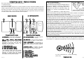
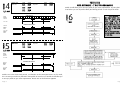
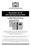
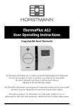
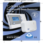
TH
US ERM
ER O
IN PLU
ST S
RU AS
CT 2IO RF
NS
The Horstmann ThermoPlus AS2-RF - Programmable Room Thermostat with
wireless communication technology.
INTRODUCTION
The Horstmann ThermoPlus AS2-RF is a wireless room thermostat that has been designed
to make its operation very simple for the householder.
The built in automatic clock means it will not need setting or adjusting for BST and GMT
time changes.
The ThermoPlus will provide a Warm temperature setting at times pre-set by your installer
and day-to-day user adjustments are carried out using just three buttons.
The ThermoPlus AS2-RF is supplied in two parts. The receiver which is hard wired to the
combi or conventional system boiler and the AS2-RF thermostat which can be used in any
normal domestic environment within a typical 30 metre range without the need for any
costly or disruptive wiring.
Email: [email protected]
Website: www.horstmann.co.uk
Page 16
Horstmann Controls Limited
Bristol
BS4 1UP
LEAFLET No P83020
ISSUE 1
Page 1
THERMOPLUS AS2-RF - PRODUCT OVERVIEW
The AS2-RF thermostat kit is made up of two parts:
1 x ASR-RF Receiver
1 x AS2-RF Transmitter
Both parts have been designed to be easily installed and offer maximum flexibility. No hard
wiring is required between the transmitter and the receiver. The receiver unit is hard wired to
the boiler and should be sited close to the existing wiring. The AS2-RF can then be positioned
up to 30 metres away - Range will vary depending upon the composition, density and number
of walls between the AS2-RF transmitter and the receiver.
AS2-RF TRANSMITTER
ASR-RF RECEIVER
1
2
3
A
4
D
E
B
C
F
G
H
ThermoPlus ASR-RF Receiver
ThermoPlus AS2-RF Transmitter
LED INDICATOR - The tri-colour LED gives the
status indication to the user and installer.
LCD DISPLAY FEATURES - A fully graphical
back-lit installer and user display.
EASY TO USE PAIRING AND OVERRIDE
BUTTONS - Simple to identify colour coded
buttons allow you to connect the
transmitter and receiver. They also allow
override of the boiler without the
transmitter. (see section 3)
LED INDICATOR - Red and Blue indicators
show if you are in a ‘Warm’ or ‘Cool’ period.
1 - Status Indicator LED
2 - AS2-RF Add/Remove Buttons
3 - Boiler ‘Off’ Override** (Red)
4 - Boiler ‘On’ Override** (Green)
**The override facility will only operate
when a flashing amber LED is showing. This
indicates no signal from the AS2-RF
transmitter is being received, the position
and battery level should be checked.
Page 2
What is a room thermostat?
... an explanation for householders
A room thermostat simply switches the heating system on
and off as necessary. It works by sensing the air
temperature, switching on the heating when the air
temperature falls below the thermostat setting, and
switching it off once this set temperature has been
reached.
Turning a room thermostat to a higher setting will not
make the room heat up any faster. How quickly the room heats up depends on the design of the
heating system, for example, the size of boiler and radiators.
Neither does the setting affect how quickly the room cools down. Turning a room thermostat to a lower
setting will result in the room being controlled at a lower temperature, and saves energy.
The heating system will not work if a time switch or programmer has switched it off.
The way to set and use your room thermostat is to find the lowest temperature setting that you are
comfortable with, and then leave it alone to do its job. The best way to do this is to set the room
thermostat to a low temperature - say 18oC - and then turn it up by one degree each day until you are
comfortable with the temperature. You won't have to adjust the thermostat further. Any adjustment
above this setting will waste energy and cost you more money.
If your heating system is a boiler with radiators, there will usually be only one room thermostat to
control the whole house. But you can have different temperatures in individual rooms by installing
thermostatic radiator valves (TRVs) on individual radiators. If you don't have TRVs, you should choose
a temperature that is reasonable for the whole house. If you do have TRVs, you can choose a slightly
higher setting to make sure that even the coldest room is comfortable, then prevent any overheating
in other rooms by adjusting the TRVs.
Room thermostats need a free flow of air to sense the temperature, so they must not be covered by
curtains or blocked by furniture. Nearby electric fires, televisions, wall or table lamps may prevent the
thermostat from working properly.
The above explanation has been kindly provided by the association of heating controls
manufacturers as a guide to encouraging the correct and efficient use of heating controls.
PRESET PROGRAMMES - Programming is
made simple and a one touch override
facility makes temporary changes simple to
use.
AUTOMATIC CLOCK - A factory set clock
which automatically adjusts between
winter (GMT) and summer (BST) time.
A - Plus ‘+’ Button
B - LED Indicator lights
C - Installer Display
D - ‘Warm/Cool’ Button
E - Minus ‘-’ Button
F - Standby / Time / Set Button
G - Increase / Decrease Buttons
H - Prog / Exit Button
For more information on Z Wave technology
please visit;
www.zen-sys.com
Page 15
INDEX
INTRODUCTION
PRODUCT OVERVIEW
SECTION 1 - UNDERSTANDING THE AS2-RF
PAGE 1
PAGE 2
SECTION 1 - UNDERSTANDING THE AS2-RF;
INDICATING LIGHTS AND BACK-LIT DISPLAY
STANDBY / FROST PROTECTION
POWER DOWN MODE
PAGE 3
PAGE 3
PAGE 3
SECTION 2 - SETTINGS AND ADJUSTMENT
WARM AND COOL TEMPERATURE ADJUSTMENT
AS2-RF PROGRAMMING MODE
AS2-RF TIME ALTERATION
SETTING HEATING PROFILES
HEATING PROFILES (1-3)
HEATING PROFILES (4-5)
PROFILE 6 - USER DEFINABLE
PAGE 4
PAGE 5
PAGE 5
PAGE 6
PAGE 7
PAGE 8
PAGE 9
INDICATING LIGHTS AND BACK-LIT DISPLAY
The ThermoPlus AS2-RF is battery powered and is intended for applications where no mains
supply is readily available to operate the unit. To conserve battery life, the indicator lights and
the display backlighting will go out after 8 seconds. The LCD target temperature display will
remain on, but not back-lit, at all times.
The LED indicators will illuminate whenever the ‘+/-’ or ‘Warm/Cool’ buttons are pressed. The
back-lit display will also operate whenever any of the buttons located under the flap are
pressed. ‘
The LED indicators will convey the heating status by adjusting the number and colour of the
LED’s displayed;
- ‘Warm’ is shown by two red lights - Adjustment to this temperature of 1oC can be made by
pressing the ‘+’ button, to a maximum increase of 2oC, and the ‘-’ button to a maximum
decrease of 2oC
- ‘Cool’ is shown by a single blue light - The '+' and '-' buttons have no effect on the lower
temperature setting
PLEASE NOTE; The centre button marked 'Warm/Cool' allows you to toggle between the Warm
and Cool settings.
SECTION 3 - UNDERSTANDING THE RECEIVER;
RF TECHNOLOGY
STATUS INDICATOR LED
FAIL SAFE MODE
PAGE 10
PAGE 10
PAGE 11
SECTION 4 - GENERAL INFORMATION
RESETTING THE AS2-RF
OPERATING MODES
BATTERY REPLACEMENT
SERVICE AND REPAIR
WHAT IS A THERMOSTAT?
Page 14
PAGE 12
PAGE 12
PAGE 13
PAGE 13
PAGE 15
STANDBY / FROST PROTECTION
The blue button situated under the flap will initiate the
frost protection mode when pressed, the word
’STANDBY’ will appear on the display, the thermostat
has been pre-programmed with a frost protection
temperature level of 7oC, this can be adjusted by using
the up and down arrow buttons. To resume normal
operation press the blue button to cancel the frost
protection.
PRESS FOR STANDBY / FROST PROTECTION
POWER DOWN MODE
During normal operation the AS2-RF will go into Power Down Mode, this is to maximise the life
of the 3 x AA batteries fitted. Normal operation will continue during this mode, and the heating
will be unaffected. The result of the Power Down Mode will mean that the LED indicators will
not be displayed and LCD will not be illuminated, although the ‘Warm’ or ‘Cool’ temperature will
be displayed.
To ‘wake up’ the AS2-RF press the ‘Warm/Cool’ button for 5 seconds, this will then illuminate
both the LED and LCD displays for a period. Any adjustment can then be made, the Power Down
Mode will commence again approximately 8 seconds after the last button press.
Page 3
SECTION 2 - SETTINGS AND ADJUSTMENT
SERVICE AND REPAIR
WARM AND COOL TEMPERATURE ADJUSTMENT(PERMANENT)
The ThermoPlus has two preset temperature levels, these are known as;
- ‘Warm’, higher level temperature(21oC)
- ‘Cool’, lower or set back temperature (15oC).
The preset temperatures have been selected to give a comfortable, safe, yet efficient
temperature level in the home.
In certain installations it may be necessary to adjust either the ‘Warm’ or ‘Cool’ temperatures
to meet the specific needs of the user. This can be achieved by following the simple steps
below;
The ThermoPlus AS2-RF is NOT user serviceable. Please do not dismantle the unit.
In the event of a fault developing please refer to the RESETTING THE THERMOSTAT section of this
user guide. If this fails to resolve the problem please contact a local heating engineer or a
qualified electrician.
NOTES
To change a target temperature it is first necessary to press the
the centre button to bring up the ‘Warm’ or ‘Cool’ setting
(Indicated by the red or blue LED indicators).
Use the up/down keys under the flap to increase or decrease to
the desired temperature setting
PLEASE NOTE - it is not possible to set the ‘Warm’ setting to
below that of the ‘Cool’ setting or vice versa.
Once a new temperature has been set in either the Warm or Cool
setting the AS2-RF will continue to use this setting until the next
manual adjustment.
Warm/Cool
Up/Down
WARM TEMPERATURE ADJUSTMENT(TEMPORARY)
The temperature settings on the AS2-RF will have been set by
the installer to match your lifestyle, however if any temporary
increase or decrease to the ‘Warm’ setting is required you can
press the ‘+’ or ‘-’ buttons. The temperature change will be
indicated by both the LED and LCD user displays
PLEASE NOTE;
- This is a temporary change and will revert back to the normal
setting at the next programmed ‘Warm/Cool’ change.
- This does not indicate a permanent change in the ‘Warm’
settings.
- During an override the word ‘Warm’ will disappear from the
LCD display indicating an override is active.
- The ‘+’ and ‘-’ buttons have no effect on the ‘Cool’ setting
Page 4
Page 13
SECTION 4 - GENERAL INFORMATION
RESETTING THE AS2-RF TRANSMITTER
Electronic equipment can in some circumstances be affected by electrical interference. If the
display becomes frozen or scrambled; or if you wish to revert back to the default settings
please use the following procedure.
PLEASE NOTE; Using this procedure will restore the AS2-RF to the original factory settings, the
time of day will also revert to 1/1/06, details of how to adjust the time are contained within
the user guide.
RESETTING THE THERMOPLUS AS2-RF
- On the ThermoPlus AS2-RF press the ‘UP’ and
‘DOWN’ arrow buttons together:
- Then release the buttons and the thermostat will
return to preset factory settings.
TO RESET PRESS
BATTERY REPLACEMENT
The ThermoPlus AS2-RF uses 3 x AA(LR6) batteries. The batteries supplied with the unit should
last for approximately two years. When the batteries are nearing the end of their life a ‘LOW
BAt’ message will flash on the display.
AS2-RF PROGRAMMING MODE
The ThermoPlus AS2-RF has been designed to operate with as little as possible adjustment by
the user.
However, should any programming adjustments be required then lift the flap and press the two
outer buttons simultaneously. This will allow you to enter the programming mode to check and
adjust any of the following
;
- Check the current time/date/year
- Check the current profile
- Set a new pre-set or user defined profile
PLEASE NOTE; Upon completion of any changes/reviews
made, please ensure that you exit the programming
mode using the same two buttons.
Press
AS2-RF TIME ALTERATION
The ThermoPlus thermostat has been pre-set with the current time and date during
manufacture. No alteration should be required to the time and date, however if any
modification is required please refer to the flowchart below.
To change the batteries it is necessary to remove the AS2-RF from the wall, to achieve this first
press the RELEASE BUTTONS located under the unit and pull the AS2-RF away from the mounting
plate by gently pulling up.
Remove the old batteries and replace them with three new AA size alkaline batteries, ensure
they are fitted correctly as shown by the marking positioned between the battery terminals.
Once batteries have been fitted, replace the AS2-RF to the mounting plate, ensuring that the
two guide lugs are fitted into the corresponding slots in the top of the mounting plate. Now
push the AS2-RF until the release button clicks into place.
WARNING : You must always ensure that the AS2-RF is always running on 3 x AA batteries, when
the battery low message is indicated it is impotant that they are exchanged as soon as possible.
This is to preserve the secondary internal reserve battery which is non-replaceble.
OPERATING MODES
During normal operation the receiver will indicate the boiler status through the colour of its LED,
please refer to the receiver STATS INDICATOR LED section of this guide.
The AS2-RF also uses a combination of LED and LCD displays to assist the user to gain maximum
benefit from the thermostat, during normal operating periods, where no user intervention has
occurred, the AS2-RF will power down to maximise battery life, to ‘wake’ the AS2-RF press the
Warm/Cool for 5 seconds, the displays, both LED and LCD, will now illuminate and will stay lit
for a period of 8 seconds after the last button press.
Page 12
Page 5
COMMUNICATION FAIL SAFE MODES
SETTING HEATING PROFILES
The ThermoPlus contains a selection of five pre-set and one user definable profile options, one
of these may have been set by the Installer. Care should be taken to ensure a profile is selected
that suits the lifestyle of the user concerned.
The flow chart below is designed to easily guide you through the process of setting the required
profile.
Profiles one to five are detailed on pages 7 and 8.
If none of the pre-set profiles meet your requirements it is possible to set a user defined profile,
full details are given on page 9.
RECEIVER FAIL SAFE MODE
Should your receiver enter the Fail Safe Mode this will be conveyed by the LED indicator going
solid amber. This will only happen if the receiver has not received a signal from the AS2-RF for
more than 60 minutes. Some basic instructions are detailed in the section above and on the
inside of the receiver flap for the emergency use of the relay/heating during this mode.
To resume normal operation please use the following procedures;
1. Press the ‘warm/cool’ button on the front of the AS2-RF for 5 seconds, or until the display
illuminates, then press again to send a signal to the receiver receiver, if successful this will be
indicated by the LED on the receiver changing from amber to either red or green.
or
2. Check and replace, if necessary, the 3 x AA batteries in the AS2-RF transmitter, then follow
process (1) above.
3. If process (1) and (2) fail to regain normal operation then please consult your heating or
service engineer for further assistance.
AS2-RF NO SIGNAL INDICATOR
Should your AS2-RF enter the Fail Safe Mode this will be conveyed by the LCD display showing
‘No Sig’ every 3 seconds. This indicates that the AS2-RF has not received a signal to confirm the
last ‘Warm/Cool’ change from the receiver.
To resume normal operation please use the following procedures;
1. Press the ‘Warm/Cool’ button on the front of the AS2-RF for 5 second, or until the display
illuminates, then press again to send a signal to the receiver receiver, if successful this will make
the ‘No sig’ flag disappear
or
Profiles one to five have fixed programmes, they can be reviewed by
pressing the set button once the selection process detailed above has
been completed. To set a custom profile please refer to the instructions
on page 9.
Page 6
2. Check the receiver receiver, if the LED is not illuminated this indicates a power interruption
or disconnection. Check the 3A fused spur supply, if the LED then illuminates on the receiver
then press any button on the AS2-RF to reconnect.
if checking the 3A spur supply fails to illuminate the LED then the assistance of an electrician or
service engineer should be sought.
Page 11
The AS2-RF thermostat uses radio frequency technology to
communicate wirelessly between the receiver and
transmitter. This makes the AS2-RF ideal for fitting in either
new or existing systems where additonal wiring cannot be
used for either practical or cosmetic reasons. The receiver and
AS2-RF use Z-wave technology to communicate, this means it
can be used as a stand alone item or added to an existing Zwave installation.
RECEIVER STATUS INDICATOR (LED) LIGHT
The Tri-coloured LED on the receiver allows both the installer and the end user to understand
the status of communication between the receiver and the AS2-RF.
The LED has six different indications, these are;
INSTALLATION MODE;
PLEASE NOTE; These will not be visible during normal user operation,
users should not attempt to re-commission an existing installation, please consult your service
engineer for assistance.
Flashing Red - No network connection, please refer to
‘COMMISSIONING INSTRUCTIONS’ section of the
installation guide.
Flashing Green - Indicates a successful network connection.
ONE’ has
The ThermoPlus has six heating profiles, five are fixed and one is adjustable. Profile ‘O
been set as the default and is detailed below. During installation a heating profile should have
been set to best match your requirements, illustrations of the pre-set profiles are shown
below.
PROFILE
RF TECHNOLOGY
HEATING PROFILES
1
Time
Solid Red - Heating off
Solid Green - Heating on
FAIL SAFE MODE
If, during normal operation, the RF signal is lost for more than 60
minutes then the receiver will switch to Fail Safe Mode(off). During Fail Safe Mode the receiver
relay/heating will be switched off and can be controlled by using the emergency red(off) and
green(on) buttons located below the flap on the receiver if required, further details are given
in the following sections. When the emergency buttons are used the LED will operate in the
following way;
Solid Amber - Heating off - indicating no message from AS2-RF for
60 minutes Flashing Amber - Heating on - Green override button activated
2
3
4
5
6
7
STATUS
WARM
COOL
TIME PROFILE
8 9 10 11 12 13 14 15 16 17 18 19 20 21 22 23 00
TEMPERATURE PROFILE
Warm
Cool
2
PROFILE TWO
EVERY DAY
START
06:00
08:00
17:00
22:30
STATUS
WARM
COOL
WARM
COOL
24 Hour
1
2
3
4
5
6
7
TIME PROFILE
8 9 10 11 12 13 14 15 16 17 18 19 20 21 22 23 00
Profile
TEMPERATURE PROFILE
Warm
Cool
PROFILE
The following LED indications should be present during normal
1
START
06:00
22:00
Profile
Time
NORMAL OPERATION;
operation;
PROFILE ONE - DEFAULT
EVERY DAY
24 Hour
PROFILE
SECTION 3 - UNDERSTANDING THE RECEIVER
PROFILE THREE
EVERY DAY
3
24 Hour
Time
1
2
3
4
5
6
7
START
06:00
08:00
11:30
13:30
17:00
22:30
STATUS
WARM
COOL
WARM
COOL
WARM
COOL
TIME PROFILE
8 9 10 11 12 13 14 15 16 17 18 19 20 21 22 23 00
Profile
PLEASE NOTE; The red and green override buttons on the receiver will only operate in fail safe
mode. In normal operation pressing these buttons will have no effect.
TEMPERATURE PROFILE
Warm
Cool
Page 10
Page 7
START
06:00
08:00
11:30
13:30
17:00
22:30
5/2 DAY
Time
Profile
1
2
3
4
5
6
7
STATUS
WARM
COOL
WARM
COOL
WARM
COOL
SAT/SUN
START
07:00
22:00
Profile six will allow you to set up a profile to your exact requirements. By using the flow
chart below you can adjust the Warm/Cool timing periods on each day of the week.
TIME PROFILE
8 9 10 11 12 13 14 15 16 17 18 19 20 21 22 23 00
MON-FRI
SAT / SUN
TEMPERATURE PROFILE
Warm
Cool
SAT / SUN
Warm
Cool
PROFILE
6
7 DAY
MON-FRI
5
PROFILE SIX
USER DEFINABLE - 7 DAY PROGRAMMING
STATUS
WARM
COOL
PROFILE
PROFILE
4
PROFILE FOUR
MON - FRI
PROFILE FIVE
MON - FRI
START
06:00
08:00
17:00
22:30
STATUS
WARM
COOL
WARM
COOL
SAT/SUN
START
07:00
22:00
COPY FEATURE
The copy feature can be
used to apply changes
made from one days
programming to the next.
This is achieved by pressing
the down arrow button
when ‘SET’ is displayed on
the screen.
‘SET’ is displayed after the
last cool period is confirmed
on each day.
STATUS
WARM
COOL
5/2 DAY
Time
Profile
1
2
3
4
5
6
7
TIME PROFILE
8 9 10 11 12 13 14 15 16 17 18 19 20 21 22 23 00
MON-FRI
SAT / SUN
TEMPERATURE PROFILE
MON-FRI
Warm
Cool
SAT / SUN
Warm
Cool
Profiles one to five have fixed periods, no alteration to the Warm/Cool times can be made,
if it is necessary to make any alterations then profile six must be used. Profile six will allow you
to set up a profile to your exact requirements. Please refer to the flowchart opposite
Page 8
Page 9