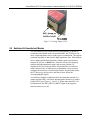
1
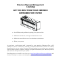
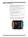
Instruction Manual Document: CI-CW-GFC-ISTRAN Part: D301647X012 November, 2009 ControlWave GFC IStran ControlWave GFC IStran Intrinsically Safe Communication Interface Remote Automation Solutions www.EmersonProcess.com/Remote IMPORTANT! READ INSTRUCTIONS BEFORE STARTING! Be sure that these instructions are carefully read and understood before any operation is attempted. Improper use of this device in some applications may result in damage or injury. The user is urged to keep this book filed in a convenient location for future reference. These instructions may not cover all details or variations in equipment or cover every possible situation to be met in connection with installation, operation or maintenance. Should problems arise that are not covered sufficiently in the text, the purchaser is advised to contact Emerson Process Management, Remote Automation Solutions division (RAS) for further information. EQUIPMENT APPLICATION WARNING The customer should note that a failure of this instrument or system, for whatever reason, may leave an operating process without protection. Depending upon the application, this could result in possible damage to property or injury to persons. It is suggested that the purchaser review the need for additional backup equipment or provide alternate means of protection such as alarm devices, output limiting, fail-safe valves, relief valves, emergency shutoffs, emergency switches, etc. If additional information is required, the purchaser is advised to contact RAS. RETURNED EQUIPMENT WARNING When returning any equipment to RAS for repairs or evaluation, please note the following: The party sending such materials is responsible to ensure that the materials returned to RAS are clean to safe levels, as such levels are defined and/or determined by applicable federal, state and/or local law regulations or codes. Such party agrees to indemnify RAS and save RAS harmless from any liability or damage which RAS may incur or suffer due to such party's failure to so act. ELECTRICAL GROUNDING Metal enclosures and exposed metal parts of electrical instruments must be grounded in accordance with OSHA rules and regulations pertaining to "Design Safety Standards for Electrical Systems," 29 CFR, Part 1910, Subpart S, dated: April 16, 1981 (OSHA rulings are in agreement with the National Electrical Code). The grounding requirement is also applicable to mechanical or pneumatic instruments that include electrically operated devices such as lights, switches, relays, alarms, or chart drives. EQUIPMENT DAMAGE FROM ELECTROSTATIC DISCHARGE VOLTAGE This product contains sensitive electronic components that can be damaged by exposure to an electrostatic discharge (ESD) voltage. Depending on the magnitude and duration of the ESD, this can result in erratic operation or complete failure of the equipment. Read supplemental document S14006 for proper care and handling of ESD-sensitive components. Remote Automation Solutions A Division of Emerson Process Management 1100 Buckingham Street, Watertown, CT 06795 Telephone (860) 945-2200 Emerson Process Management Training GET THE MOST FROM YOUR EMERSON INSTRUMENT OR SYSTEM Avoid Delays and problems in getting your system on-line Minimize installation, start-up and maintenance costs. Make the most effective use of our hardware and software. Know your system. As you know, a well-trained staff is essential to your operation. Emerson offers a full schedule of classes conducted by full-time, professional instructors. Classes are offered throughout the year at various locations. By participating in our training, your personnel can learn how to install, calibrate, configure, program and maintain your Emerson products and realize the full potential of your system. For information or to enroll in any class, go to http://www.EmersonProcess.com/Remote and click on “Training” or contact our training department in Watertown at (860) 945-2200. BLANK PAGE ControlWave GFC-IStran Instruction Manual Contents Chapter 1 – Introduction 1.1 1-1 Physical Description..................................................................................................................1-2 1.1.1 IStran PCB ....................................................................................................................1-3 Chapter 2 – Function and Electrical Characteristics 2.1 2.2 2.3 Hazardous and Non-Hazardous Characteristics.......................................................................2-1 2.1.1 Hazardous Interface......................................................................................................2-1 2.1.2 Non-Hazardous Interface ..............................................................................................2-3 Switched & Unswitched Modes.................................................................................................2-5 2.2.1 Configuring the Hazardous Interface for Switched Mode .............................................2-6 2.2.2 Configuring the Hazardous Interface for Unswitched Mode .........................................2-6 2.2.3 Configuring the Non-Hazardous Interface for Switched Mode .....................................2-6 2.2.4 Configuring the Non-Hazardous Interface for Unswitched Mode .................................2-6 Non-Hazardous Power Output ..................................................................................................2-6 Chapter 3 – System Wiring 3.1 3.2 3.3 3.4 3-1 Introduction to System Wiring ...................................................................................................3-1 Grounding..................................................................................................................................3-1 Cable Length .............................................................................................................................3-2 Field Wiring Diagrams...............................................................................................................3-2 Chapter 4 – Installation 4.1 4.2 4-1 Installation Overview .................................................................................................................4-1 Installation Notes.......................................................................................................................4-1 Chapter 5 – Specifications 5.1 5.2 2-1 5-1 Environment ..............................................................................................................................5-1 Operating Specifications ...........................................................................................................5-1 Index Issued Nov-09 I-1 Contents v ControlWave GFC-IStran Instruction Manual vi Contents Issued Nov-09 ControlWave GFC IS Communication Interface Manual (CI-CW-GFC-ISTRAN) Chapter 1 – Introduction The ControlWave GFC Intrinsically Safe IStran Communication Interface (IStran) allows an intrinsically safe ControlWave Gas Flow Computer / Corrector (CW-GFC-IS) to communicate with a device located in a Division 2 or non-hazardous area. Underwriter’s Laboratories (UL) approves the IStran interface with a CW-GFC-IS unit when you use it with approved intrinsically safe battery power/solar panel power, or when the CW-GFC-IS receives external power through the IStran. The IStran performs the following functions: Replaces six intrinsic safety barriers for RS-232 signals (3 in, 3 out) Provides 500V isolation between two devices Operates at speeds up to 19,200bps Allows the CW-GFC-IS to receive power from outside the Division 1 area Allows the CW-GFC-IS to control power to a radio or modem located outside the Division 1 area You can also use the IStran for certain applications where intrinsic safety is unnecessary, such as to provide isolation between two devices or to allow multiple devices to share a single radio or modem. Figure 1-1. IStran Front View Issued Nov-09 Introduction 1-1 ControlWave GFC IS Communication Interface Manual (CI-CW-GFC-ISTRAN) 1.1 Physical Description The IStran assembly measures 6.25 inches (length) by 4.50 inches (width) by approximately 1 inch (depth). (See Figure 1-2, 1-3, and 1-4.) The IStran assembly consists of the following major components: One IStran printed circuit board (PCB) for the IStran assembly Yellow alodined aluminum base plate (0.060 inch thick) Black anodized cover (0.090 inch thick) Figure 1-2. Physical Dimensions – IStran – Front View Figure 1-3. Physical Dimensions – IStran – Edge (Side) View 1-2 Introduction Issued Nov-09 ControlWave GFC IS Communication Interface Manual (CI-CW-GFC-ISTRAN) Figure 1-4. IStran PCB Mounted on Base Plate (Cover removed) 1.1.1 IStran PCB The IStran PCB provides two interfaces designated hazardous and nonhazardous. You configure each interface independently to operate in either switched or unswitched mode. Switched Mode Switched mode sets the TX drivers into a high-impedance state to reduce power consumption. Unswitched Mode In unswitched mode, the TX drivers are always active and they always follow the corresponding RX inputs. In cases where power consumption is not a key factor, configure the IStran for unswitched mode. Issued Nov-09 Introduction 1-3 ControlWave GFC IS Communication Interface Manual (CI-CW-GFC-ISTRAN) 1-4 Introduction Issued Nov-09 ControlWave GFC IS Communication Interface Manual (CI-CW-GFC-ISTRAN) Chapter 2 – Function and Electrical Characteristics You can use the ControlWave GFC Intrinsically Safe IStran Communication Interface (IStran) in both hazardous and nonhazardous environments. 2.1 Hazardous and Non-Hazardous Characteristics Table 2-1 provides the characteristics common to both the hazardous and non-hazardous IStran interfaces: Table 2-1. Common Characteristics for Hazardous and Non-Hazardous Interfaces Description Data Rate Propagation Delay, any RX to any TX Output Enable Delay (Switched Mode, enable to TX valid) RX Input High Level Maximum: Maximum: Specification 19.2 Kbps 10 uS Typical: Maximum: < 10 uS 50 uS Minimum: Maximum: Minimum: Maximum: 4.5 VDC 16 VDC -16 VDC 0.5 VDC RX Input Load Resistance TX Output Load Resistance Typical: Minimum: 3.01 Kohm 3 Kohm Quiescent Supply Current (Both if in switched mode, all TX off) Idle Supply Current (Both if in unswitched mode, all TX low) Active Supply Current (Both if active, worst case) Maximum: 800 uA Typical: 21 mA Maximum: 43 mA RX Input Low Level 2.1.1 Hazardous Interface You connect the hazardous interface to an intrinsically safe device. Table 2-2, identifies each connector position, the corresponding signal name, and briefly describes each input/output point on the hazardous interface. Table 2-2. Hazardous Interface Connector Position Issued Nov-09 Name Function HJ2-4 HPOUT Hazardous Power Output - connect to HJ1-3 (HPIN) for single supply applications HJ2-3 HPIN Hazardous Power Input HJ2-2 HGND Hazardous Interface Ground - connect to HJ21 (CGND) for single supply applications HJ2-1 CGND Enclosure Ground (Tied to NGND) HJ1-8 HGND Hazardous Interface Ground - (Reference for Function and Electrical Characteristics 2-1 ControlWave GFC IS Communication Interface Manual (CI-CW-GFC-ISTRAN) Position Name Function HPOUT and signals) HJ1-7 HPOUT Hazardous Power HJ1-6 HRX3 Signal Input HJ1-5 HRX2 Signal Input HJ1-4 HJ1-3 HJ1-2 HJ1-1 HJP1-1 HJP1-2 HJP1-3 HRX1 HTX3 HTX2 HTX1 SW COM UNSW Signal Input Signal Output (Follows NRX3) Signal Output (Follows NRX2) Signal Output (Follows NRX1) Jumper to COM for Switched Mode Mode Selection Common Jumper to COM for Unswitched Mode Table 2-3 provides the characteristics of the hazardous interface. Table 2-3. Hazardous Interface Characteristics Description 2-2 Specification HPOUT Voltage Typical Minimum: Maximum: 6.3 VDC (No Load) 5.9 VDC (Max. Load) 6.4 VDC (No Load) HPOUT Current Limit Threshold Minimum: Maximum: 130 mA at 8 VDC 300 mA at 16 VDC HPOUT Load Capacitance Maximum: 100 uF HPIN Quiescent Supply Current (Switched Mode, Transmitters Off) Maximum: 100 uA HPIN Supply Current (All TX Outputs High, 3 KW Load Maximum: 6 mA HTX Output High Level Minimum: VDC 4.5 VDC, Maximum: 5.0 HTX Output Low Level Minimum: VDC 0 VDC, Maximum: 0.1 HJP1 Jumper Operation If you don’t install a jumper, or if you install the jumper between pins 1 and 2 (SW), the hazardous interface operates in switched mode. If you install the jumper between pins 2 and 3 (UNSW), the hazardous interface operates in unswitched mode. Figure 2-1 shows the jumper in switched mode. Function and Electrical Characteristics Issued Nov-09 ControlWave GFC IS Communication Interface Manual (CI-CW-GFC-ISTRAN) Figure 2-1. Setting Jumper HJP1 2.1.2 Non-Hazardous Interface Typically you connect the non-hazardous interface to a radio or modem located with the IStran assembly in a non-hazardous or Division 2 rated area. Table 2-4 identifies each connector position and the corresponding signal name, and provides a brief description of each I/O point on the non-hazardous interface. Table 2-4. Non-Hazardous Interface Connector Position Issued Nov-09 Name Function NJ3-1 NPOUT Switched Power Output NJ3-2 NGND Local Ground reference (Return for NPOUT) NJ2-1 NPIN Power Supply Input NJ2-2 NGND Local Ground (Return for NPIN) NJ1-1 NTX1 Signal Output (Follows HRX1) NJ1-2 NTX2 Signal Output (Follows HRX2) NJ1-3 NTX3 Signal Output (Follows HRX3) NJ1-4 NRX1 Signal Input NJ1-5 NRX2 Signal Input NJ1-6 NRX3 Signal Input NJ1-7 NGND Local Ground NJP1-1 SW Jumper to COM for Switched Mode NJP1-2 COM Mode Selection Common NJP1-3 UNSW Jumper to COM for Unswitched Mode Function and Electrical Characteristics 2-3 ControlWave GFC IS Communication Interface Manual (CI-CW-GFC-ISTRAN) Table 2-5 provides the characteristics of the non-hazardous interface. Table 2-5. Non-Hazardous Interface Characteristics Description 2-4 Specification NPIN Voltage (When HPOUT is not used) Minimum: Maximum: 5.4 VDC 16 VDC NPIN Voltage (When HPOUT is used) Minimum: Maximum: 8 VDC 16 VDC NPIN Supply Current (Switched Mode, Transmitters Off) Typical: C) Maximum: < 500 uA at 12 VDC, 77 F (25 NPIN Supply Current (All TX Outputs High, 3 KWLoads) Maximum: 37 mA NPOUT Leakage Typical: < 1 uA NPIN to NPOUT OnResistance (NPIN ³ 12 V) Typical: Maximum: < 0.3 ohm 0.5 ohm NRX3 to NPOUT On Typical: < 10 uS NPOUT Load Current Maximum: 1.8 A Continuous Maximum: 3.0 A Intermittent (Max 60 Seconds, 50% duty) NTX Output High Level Typical: Minimum: Maximum: 7.4 VDC into 3 Kohm Load 5.0 VDC 9.5 VDC NTX Output Low Level Typical: Minimum: Maximum: -4.9 VDC into 3 Kohm Load -9.5 VDC -3.0 VDC NJP1 Jumper Operation If you didn’t install a jumper, or if you installed a jumper between pins 1 and 2 (SW), the nonhazardous interface operates in switched mode. If you install a jumper between pins 2 and 3 (UNSW), the non-hazardous interface operates in unswitched mode. (Figure 2-2 shows the jumper in switched mode.) Function and Electrical Characteristics 750 uA Maximum: 100 uA Issued Nov-09 ControlWave GFC IS Communication Interface Manual (CI-CW-GFC-ISTRAN) Figure 2-2. Setting Jumper NJP1 2.2 Switched & Unswitched Modes You can configure each IStran interface independently to operate in switched or unswitched mode. In switched mode, the TX drivers can enter a high-impedance state to reduce power consumption. The outputs transition smoothly to and from the high-impedance state. Most modern device inputs pull the high impedance IStran output to ground and interpret it as a low, or mark state. Some devices may not properly interpret the high-impedance signal, and in some systems it is impractical for you to operate either or both interfaces in switched mode. In these cases, or when power consumption is not a concern, configure the interface(s) for unswitched mode. In unswitched mode, the TX drivers are always active and they always follow the corresponding RX inputs. You enable or disable switched mode for the hazardous interface by jumper position HJP1, and for the non-hazardous interface by jumper position NJP1 (see Figures 2-1 and 2-2). When either interface is in switched mode, the RX3 (NRX3 or HRX3) input of the opposite interface turns it on or off. Issued Nov-09 Function and Electrical Characteristics 2-5 ControlWave GFC IS Communication Interface Manual (CI-CW-GFC-ISTRAN) 2.2.1 Configuring the Hazardous Interface for Switched Mode To configure the hazardous interface for switched mode, place the supplied shorting jumper in the HJP1 position marked SW (short HJP1 pins 1 and 2 as shown in Figure 2-1). If you don’t install a jumper at HJP1 the hazardous interface defaults to switched mode. When you configure the hazardous interface for switched mode, the HTX outputs are in a high-impedance state when NRX3 is low (or negative), and the HTX outputs follow the NRX inputs normally when NRX3 is high (positive). 2.2.2 Configuring the Hazardous Interface for Unswitched Mode To configure the hazardous interface for unswitched mode, place the supplied shorting jumper in the HJP1 position marked UNSW (short HJP1 pins 2 and 3). This is the opposite jumper position of that shown in Figure 2-1. In unswitched mode, the HTX outputs remain on and they always follow the corresponding NRX inputs. 2.2.3 Configuring the Non-Hazardous Interface for Switched Mode To configure the non-hazardous interface for switched mode, place the supplied shorting jumper in the NJP1 position marked SW (short NJP1 pins 1 and 2 as shown in Figure 2-2). The non-hazardous interface is also in switched mode by default if you don’t install a jumper at NJP1. When you configure the non-hazardous interface for switched mode, the NTX outputs are in a high-impedance state when HRX3 is low (or negative), and the NTX outputs follow the HRX inputs normally when HRX3 is high (positive). 2.2.4 Configuring the Non-Hazardous Interface for Unswitched Mode To configure the non-hazardous interface for unswitched mode, place the supplied shorting jumper in the position marked UNSW (short NJP1 pins 2 and 3). This is the opposite jumper position of that shown in Figure 2-2. In unswitched mode, the NTX outputs are always turned on and they always follow the corresponding HRX inputs. 2.3 Non-Hazardous Power Output The non-hazardous power supply is routed through a FET (field effect transistor) from the power input to an output terminal. The power supply comes in on the NPIN terminal and switched power goes out on the NPOUT terminal. 2-6 Function and Electrical Characteristics Issued Nov-09 ControlWave GFC IS Communication Interface Manual (CI-CW-GFC-ISTRAN) When hazardous interface signal input HRX3 is at a high (positive) level, NPOUT turns on and can supply power to an external device. When HRX3 is at a low (or negative) level, NPOUT turns off. You determine the voltage drop between NPIN and NPOUT by multiplying the NPOUT load current by the NPIN to NPOUT on-resistance. You must also take into account the resistance of the associated field wiring when you calculate the total drop between the power supply and the load. Caution Issued Nov-09 In order to minimize resistance between NPIN and NPOUT, the IStran does not provide over-current. You must install a fuse or other means of over-current protection at the power source to prevent damage to the IStran, power source, or load in case of a short circuit or other overcurrent condition. Function and Electrical Characteristics 2-7 ControlWave GFC IS Communication Interface Manual (CI-CW-GFC-ISTRAN) 2-8 Function and Electrical Characteristics Issued Nov-09 ControlWave GFC IS Communication Interface Manual (CI-CW-GFC-ISTRAN) Chapter 3 – System Wiring This chapter includes details on grounding and wiring for the IStran. 3.1 Introduction to System Wiring The IStran connects a radio, modem, or other communications device to a ControlWave GFC-IS Flow Computer/Corrector. An IStran can also provide an intrinsically safe interface between an external power supply and RS-232 signals associated with a radio, modem or ControlWave RTU (in a non-hazardous area) and a ControlWave GFC-IS in a Class I, Division 1 area. 3.2 Grounding The IStran provides up to 500V of isolation between the hazardous and non-hazardous interfaces. When using the ground isolation capability of the IStran, devices on either side require separate power sources, and each source must power the corresponding IStran interface. Refer to the field wiring diagrams in Section 3.4 for systems with independent power sources. When isolation is not required, a single power source supplies both IStran interfaces and, optionally, both connected devices. To power both IStran interfaces using a single power source, connect the power source between NPIN and NGND. Use connector HJ2 (see Figure 1-4) as a jumper position to wire HPOUT to HPIN and HGND to CGND. Note that CGND and NGND are internally connected, and that CGND is connected to the IStran case. Refer to the field wiring diagrams in Section 3.4 for systems with a single power source. When a ground connection already exists between the power source and the ControlWave or communications device, do not wire the ground terminal on the IStran communications connector (NJ1 or HJ1). The ground reference established on the IStran power connector (NJ2 or HJ2) serves as both power supply return and signal ground reference. Wiring the communications connector ground terminal may introduce a ground loop and degrade the performance of the IStran under these circumstances. The wiring diagrams in Section 3.4 illustrate the recommended practices. For intrinsic safety applications, you must use redundant earth grounds. Both grounds must measure less than one ohm to earth. The NGND terminal provides one ground, and the case provides the other. If the mounting panel does not provide a suitable ground path, connect a 12AWG or larger ground conductor to one of the IStran mounting screws. Issued Nov-09 System Wiring 3-1 ControlWave GFC IS Communication Interface Manual (CI-CW-GFC-ISTRAN) 3.3 Cable Length Underwriter’s Laboratories (UL) lists the IStran for use with cable lengths up to 25 feet on either or both interfaces. Typically, you install the IStran in close proximity to the communications device (connected to the non-hazardous interface) and at some distance from the CWGFC-IS (connected to the hazardous interface). Because of cable capacitance and inductance, 25 feet is the maximum cable length allowable for use with a CW-GFC-IS located in a Division 1 area. Warning The cable length between a CW-GFC-IS operating in a Division 1 area and the IStran must not exceed 25 feet. 3.4 Field Wiring Diagrams Figure 3-1 illustrates a typical communication system. The power source to the non-hazardous interface must not use or generate more than 250V. If you install the IStran in a Division 2 area, you must make power input and output connections using Division 2 wiring methods described in Section 4.1. In this example a single power source supplies both the communications device and the CW-GFC-IS. The power supply input range for this configuration is 8 to 16V. You connect the grounds of both devices together through the IStran. The CW-GFC-IS power supply current must be 120mA or less, and it must operate down to 5.9V. The IS termination panel (part number 400135-01-9) contains the power and communication connections. Figure 3-1. Modem System with Single Power Source 3-2 System Wiring Issued Nov-09 ControlWave GFC IS Communication Interface Manual (CI-CW-GFC-ISTRAN) Figure 3-2 is similar to Figure 3-1 except it uses an MDS radio instead of a modem. Figure 3-2. Radio System with Single Power Source Figures 3-3 and 3-4 illustrate an externally powered CW-GFC-IS (without a modem or radio). In this example, the external power source to the non-hazardous interface must not generate more than 16Vdc and must be able to supply at least 8Vdc. If you install the IStran in a Division 2 area, you must connect the power inputs and outputs using Division 2 wiring methods. (See Section 4.1.) Note: If you only require a modem or radio, refer to Figure 3-1 and Figure 3-2. The only difference is that you can replace the 12V battery by an external 8 to 16 Vdc power supply. Figure 3-3. CW-GFC-IS with External Power Source Issued Nov-09 System Wiring 3-3 ControlWave GFC IS Communication Interface Manual (CI-CW-GFC-ISTRAN) Figure 3-4. CW-GFC-IS with External Power Supply 3-4 System Wiring Issued Nov-09 ControlWave GFC IS Communication Interface Manual (CI-CW-GFC-ISTRAN) Chapter 4 – Installation 4.1 Installation Overview The IStran and the communications device reside in a non-hazardous or Division 2 rated area, while the CW-GFC-IS resides in a Division 1, Division 2, or non-hazardous area. You must provide a suitable enclosure for the IStran. When you mount the IStran in a Division 2 area, you must make the non-hazardous interface connections in accordance with Article 501-4(b) of the National Electrical Code NFPA 70. Caution When you connect the IStran to a CW-GFC-IS mounted in a Division 1 area, wire all circuits according to wiring methods specified in article 504 of the National Electrical Code NFPA 70. Contact your IStran supplier for assistance. Warning When you install the IStran in a Division 2 area, ensure that the area is non-hazardous before you connect or disconnect the non-hazardous interface. 4.2 Installation Notes Use four #6 screws with lock washers to secure the IStran to a grounded metal panel. Illustrations in Chapter 1 show the physical dimensions of the IStran units. The four mounting holes/slots are 0.156" in diameter. Total height is approximately 1". The case material is 5052 aluminum with a black anodize finish. The thickness of the base is 0.060", and the top is 0.090". The case hardware is stainless steel. The IStran accepts stranded wires up to 14AWG. When you must insert two wires in a single position, 18AWG is the maximum recommended size. The recommended strip length is 1/4 inch, and the insulation must not extend into the connector clamp. For cables, use 26AWG or larger conductors and do not configure them as twisted pairs. If you use a shield, connect it only at one end, closest to the system ground reference. For optimum performance over long distances, use lowcapacitance cables. In the multi-drop configuration, keep all IStran units in close proximity. Secure all wiring before you apply power to the IStran or to the associated devices. For intrinsic safety applications, use a single cable to connect the IStran hazardous interface to the intrinsically safe device. Maintain a minimum 2” separation between the intrinsically safe wiring and all other wiring. Install the IStran hazardous interface near the point where the intrinsically safe wiring exits the enclosure housing the Issued Nov-09 Installation 4-1 ControlWave GFC IS Communication Interface Manual (CI-CW-GFC-ISTRAN) IStran. Do not install any other wiring through the same hole or allow other wires to share a cable or conduit with the intrinsically safe wiring. Secure the intrinsically safe wiring and limit slack to ensure that, should one of the intrinsically safe wires become dislodged from an IStran terminal, it must still maintain a 2” separation with either the IStran non-hazardous interface wiring or any other circuits except those on the IStran hazardous interface. Refer to Figures 3-1 through 3-4 in Chapter 3 when you connect wires between an optional modem or radio and an IStran assembly. Note: MDS and Freewave radios use different RXD/TXD naming conventions. MDS uses RXD and TXD to mean “receive input” and “transmit output” respectively, while Freewave uses RXD for “transmit output” and TXD for “receive input.” Refer to Chapter 3 when you connect wires between an externally powered CW-GFC-IS and an IStran. 4-2 Installation Issued Nov-09 ControlWave GFC IS Communication Interface Manual (CI-CW-GFC-ISTRAN) Chapter 5 – Specifications 5.1 Environment The IStran design supports operation inside a building or a weatherproof enclosure only. 5.2 Operating Specifications Table 5-1 provides the operating specifications for the IStran: Table 5-1. IStran Operating Specifications Description Operating Temperature Range Specification -40oC to +70oC (-40oF to +158oF) Operating Humidity Range 15% to 95% RH (non-condensing) Transient Susceptibility Field connected circuits designed to meet requirements of ANSI/IEEE C37.90.1-1989 (formerly IEEE 472) for surge withstand capability. Vibration Effect 10 to 500 Hz at 1 g on any axis per SAMA PMC-311 without damage or impairment. ESD Susceptibility Field connected circuits designed to meet the requirements of IEC 801-2 for ESD withstand capability up to 10KV. EMI Compatibility Designed to meet the susceptibility requirements of IEC 801-3 level 2(3V/M) from 500kHz to 500MHz. Designed to meet FCC Rules Part J, Subpart 15, Class A for radiated emissions. Hazardous Locations Designed to meet NFPA and UL requirements for installation in Class I, Division 2, Groups C and D hazardous locations. Designed to meet NFPA and UL requirements for connection to intrinsically safe devices located in Division 1 locations. The intrinsically safe device must be designed and/or approved for the intended connection. Issued Nov-09 Specifications 5-1 ControlWave GFC IS Communication Interface Manual (CI-CW-GFC-ISTRAN) 5-2 Specifications Issued Nov-09 WARRANTY A. Remote Automation Solutions (RAS) warrants that goods described herein and manufactured by RAS are free from defects in material and workmanship for one year from the date of shipment unless otherwise agreed to by RAS in writing. B. RAS warrants that goods repaired by it pursuant to the warranty are free from defects in material and workmanship for a period to the end of the original warranty or ninety (90) days from the date of delivery of repaired goods, whichever is longer. C. Warranties on goods sold by, but not manufactured by RAS are expressly limited to the terms of the warranties given by the manufacturer of such goods. D. All warranties are terminated in the event that the goods or systems or any part thereof are (i) misused, abused or otherwise damaged, (ii) repaired, altered or modified without RAS consent, (iii) not installed, maintained and operated in strict compliance with instructions furnished by RAS or (iv) worn, injured or damaged from abnormal or abusive use in service time. E. These warranties are expressly in lieu of all other warranties express or implied (including without limitation warranties as to merchantability and fitness for a particular purpose), and no warranties, express or implied, nor any representations, promises, or statements have been made by RAS unless endorsed herein in writing. Further, there are no warranties which extend beyond the description of the face hereof. F. No agent of RAS is authorized to assume any liability for it or to make any written or oral warranties beyond those set forth herein. REMEDIES A. Buyer's sole remedy for breach of any warranty is limited exclusively to repair or replacement without cost to Buyer of any goods or parts found by Seller to be defective if Buyer notifies RAS in writing of the alleged defect within ten (10) days of discovery of the alleged defect and within the warranty period stated above, and if the Buyer returns such goods to the RAS Watertown office, unless the RAS Watertown office designates a different location, transportation prepaid, within thirty (30) days of the sending of such notification and which upon examination by RAS proves to be defective in material and workmanship. RAS is not responsible for any costs of removal, dismantling or reinstallation of allegedly defective or defective goods. If a Buyer does not wish to ship the product back to RAS, the Buyer can arrange to have a RAS service person come to the site. The Service person's transportation time and expenses will be for the account of the Buyer. However, labor for warranty work during normal working hours is not chargeable. B. Under no circumstances will RAS be liable for incidental or consequential damages resulting from breach of any agreement relating to items included in this quotation from use of the information herein or from the purchase or use by Buyer, its employees or other parties of goods sold under said agreement. How to return material for Repair or Exchange Before a product can be returned to Remote Automation Solutions (RAS) for repair, upgrade, exchange, or to verify proper operation, Form (GBU 13.01) must be completed in order to obtain a RA (Return Authorization) number and thus ensure an optimal lead time. Completing the form is very important since the information permits the RAS Watertown Repair Dept. to effectively and efficiently process the repair order. You can easily obtain a RA number by: A. FAX Completing the form (GBU 13.01) and faxing it to (860) 945-2220. A RAS Repair Dept. representative will return the call (or other requested method) with a RA number. B. E-MAIL Accessing the form (GBU 13.01) via the RAS Web site (www.emersonprocess.com/remote) and sending it via E-Mail to [email protected] . A RAS Repair Dept. representative will return E-Mail (or other requested method) with a RA number. C. Mail Mail the form (GBU 13.01) to Remote Automation Solutions A Division of Emerson Process Management Repair Dept. 1100 Buckingham Street Watertown, CT 06795 A RAS Repair Dept. representative will return call (or other requested method) with a RA number. D. Phone Calling the RAS Repair Department at (860) 945-2442. A RAS Repair Department representative will record a RA number on the form and complete Part I, send the form to the Customer via fax (or other requested method) for Customer completion of Parts II & III. A copy of the completed Repair Authorization Form with issued RA number should be included with the product being returned. This will allow us to quickly track, repair, and return your product to you. Remote Automation Solutions Repair Authorization Form (Providing this information will permit Remote Automation Solutions to effectively and efficiently process your return. Completion is required to receive optimal lead time. Lack of information may result in increased lead times.) Date ____________ RA # _________________ Standard Repair Practice is as follows: Variations to this is practice may be requested in the “Special Requests” section. • Evaluate / Test / Verify Discrepancy/Repair/Replace SH Line No. _________ Please be aware of the Non warranty standard charge: • There is a $100 minimum evaluation charge. The party sending in material is responsible to ensure that the materials returned are clean to safe levels, defined and/or determined by applicable federal, state and /or local law regulations or codes. Such party agrees to indemnify Remote Automation Solutions harmless to any liability or damage which Remote Automation Solutions may incur or suffer due to such party’s failure to so act. Part I Please complete the following information for single unit or multiple unit returns Address No. _____________ Address No. ____________ Bill to : _____________________________________ Ship to: ___________________________________ ____________________________________________ ____________________________________________ ____________________________________________ ____________________________________________ Purchase Order: _________________________ Contact Name: _____________________________ Phone: _____________________ Part II Fax: ______________________ E-Mail: ______________________ Please complete Parts II & III for each unit returned Model No./Part No. _________________________ Description: __________________________________ Range/Calibration: _________________________ S/N: ___________________________________ Reason for return : Failure Upgrade Verify Operation Other __________________________ 1. Describe the conditions of the failure (Frequency/Intermittent, Physical Damage, Environmental Conditions, Communication, CPU watchdog, etc.) ___________________ (Attach a separate sheet if necessary) 2. Comm. interface used: Standalone RS-485 Ethernet Other: ______________________________________ Modem (PLM (2W or 4W) or SNW) 3. What is the Firmware revision?_______________ What is the Software & version? _______________ Part III If checking “replaced” for any question below, check an alternate option if replacement is not available A. If product is deemed not repairable would you like your product: returned replaced B. If Remote Automation Solutions is unable to verify the discrepancy, would you like the product: replaced scrapped? returned *see below? * Continue investigating by contacting the customer to learn more about the problem experienced? The person to contact that has the most knowledge of the problem is: __________________ phone _________________ If we are unable to contact this person the backup person is:________________ phone _________________ Special Requests: __________________________________________________________________________________________ Ship prepaid to: Form GBU 13.01 Remote Automation Solutions, Repair Dept., 1100 Buckingham Street, Watertown, CT 06795 Phone: 860-945-2442 Fax: 860-945-2220 Rev. F 11/25/08 BLANK PAGE ControlWave GFC-IStran Instruction Manual Index Non-Hazardous power output............................. 2-6 F Field wiring diagrams.......................................... 3-2 Figures 1-1. Istran Front View ..................................... 1-1 1-2. Physical Dimensions - Istran Front View 1-2 1-3. Physical Dimensions – IStran Edge (Side) View.............................................................. 1-2 1-4. Istran PCB Mounted on Base Plate ........ 1-3 2-1. Setting Jumper HJP1 .............................. 2-3 2-2. Setting Jumper NJP1 .............................. 2-5 3-1. Modem System with Single Power Source32 3-2. Radio System with Single Power Source 3-3 3-3. CW-GFC-IS with External Power Source 3-3 3-4. CW-GFC-IS with external power supply . 3-4 G Grounding ........................................................... 3-1 H Hazardous characteristics .................................. 2-1 Hazardous interface configuring for Switched Mode ....................... 2-6 S Specifications...................................................... 5-1 Switched Mode ............................................ 1-3, 2-5 configuring the Hazardous interface for ......... 2-6 configuring the non-Hazardous interface for .. 2-6 T Tables 2-1. Common Characteristics for Hazardous and Non-Hazardous Interfaces ........................... 2-1 2-2. Hazardous Interface Connector .............. 2-1 2-3. Hazardous Interface Characteristics ....... 2-2 2-4. Non-Hazardous Interface Connector ...... 2-3 2-5. Non-Hazardous Interface Characteristics2-4 5-1. IStran Operating Specifications............... 5-1 U Un-Switched Mode....................................... 1-3, 2-5 configuring the Hazardous interface for ......... 2-6 configuring the non-Hazardous interface for .. 2-6 W Wiring .................................................................. 3-1 field wiring diagrams....................................... 3-2 N Non-Hazardous characteristics........................... 2-1 Issued Nov-09 Index I-1 Customer Instruction Manual CI-CW-GFC-ISTRAN November, 2009 ControlWave GFC IStran NOTICE Emerson Process Management Remote Automation Solutions 1100 Buckingham Street Watertown, CT 06795 Phone: +1 (860) 945-2262 Fax: +1 (860) 945-2525 www.EmersonProcess.com/Remote Emerson Process Management Remote Automation Solutions 6338 Viscount Rd. Mississauga, Ont. L4V 1H3 Canada Phone: 905-362-0880 Fax: 905-362-0882 www.EmersonProcess.com/Remote Emerson Process Management SA de CV Calle 10 #145 Col. San Pedro de los Pinos 01180 Mexico, D.F. Mexico T +52 (55) 5809-5300 F +52 (55) 2614-8663 www.EmersonProcess.com/Remote Emerson Process Management, Ltd. Remote Automation Solutions Blackpole Road Worcester, WR3 8YB United Kingdom Phone: +44 1905 856950 Fax: +44 1905 856969 www.EmersonProcess.com/Remote Emerson Process Management AP Pte Ltd. Remote Automation Solutions Division 1 Pandan Crescent Singapore 128461 Phone: +65-6770-8584 Fax: +65-6891-7841 www.EmersonProcess.com/Remote “Remote Automation Solutions (“RAS”), division of Emerson Process Management shall not be liable for technical or editorial errors in this manual or omissions from this manual. RAS MAKES NO WARRANTIES, EXPRESSED OR IMPLIED, INCLUDING THE IMPLIED WARRANTIES OF MERCHANTABILITY AND FITNESS FOR A PARTICULAR PURPOSE WITH RESPECT TO THIS MANUAL AND, IN NO EVENT SHALL RAS BE LIABLE FOR ANY INCIDENTAL, PUNITIVE, SPECIAL OR CONSEQUENTIAL DAMAGES INCLUDING, BUT NOT LIMITED TO, LOSS OF PRODUCTION, LOSS OF PROFITS, LOSS OF REVENUE OR USE AND COSTS INCURRED INCLUDING WITHOUT LIMITATION FOR CAPITAL, FUEL AND POWER, AND CLAIMS OF THIRD PARTIES. Bristol, Inc., Bristol Babcock Ltd, Bristol Canada, BBI SA de CV and the Flow Computer Division are wholly owned subsidiaries of Emerson Electric Co. doing business as Remote Automation Solutions (“RAS”), a division of Emerson Process Management. FloBoss, ROCLINK, Bristol, Bristol Babcock, ControlWave, TeleFlow and Helicoid are trademarks of RAS. AMS, PlantWeb and the PlantWeb logo are marks of Emerson Electric Co. The Emerson logo is a trademark and service mark of the Emerson Electric Co. All other trademarks are property of their respective owners. The contents of this publication are presented for informational purposes only. While every effort has been made to ensure informational accuracy, they are not to be construed as warranties or guarantees, express or implied, regarding the products or services described herein or their use or applicability. RAS reserves the right to modify or improve the designs or specifications of such products at any time without notice. All sales are governed by RAS’ terms and conditions which are available upon request. © 2009 Remote Automation Solutions, division of Emerson Process Management. All rights reserved.