1
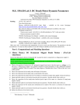
7
COUNTER AC7E
8
COUNTER AC7E
INSTRUCTIONS FOR USE
1.
Pilot lamp. Indicates, when lit, that mains power switch 2 is on.
2.
Mains power switch. Rocker switch for power supply. On/Off. Press switch down for power on.
3.
Display. 7-digit seven-segment LED display with 20 mm readout height. The result is
displayed with correct dicimal point and unit indication by LEDs 15 and 16. By result
numbering the second digit from left is blank and the result number is indicated (flashing) by the
leftmost digit.
4.
As one result only appears in this function, the sum is shown in seven digits direct on the
display as soon as the measuring has commenced with input A (LEDs 18 and 14 go out and input
A is closed). The time measurement is stopped with input B, the LED 17 goes out and the input is
closed. The time unit is indicated by the „mSec.“ LED 15.
When the test is finished, 12 emits a constant light to indicate that the only result available is
now shown on the display.
FUNCTION SELECTOR LED 14 is now on again, and when 13 is pushed in the counter
prepares itself for function selection (Described under 13).
FREQUENCY A
INPUT A - electrical impulse. The input is DC coupled with automatic gain control (AGC control).
Frequency range DC to 2 MHz. The sensitivity in the range DC to 100 kHz is typically 50 mVrms.
Sensitivity in the range 100 kHz to 2 MHz increases from the typical 50 mVrms to 500 mVrms. The
input impedance is 1 Mohm/ / 100 pF.
Do not connect higher voltage than 250 volt (DC + peak), or more than 500 volt (peak - peak).
The signal frequency connected at input A ( 4, 5 or 6 ) is continously shown on the display. The
gate time is approx. 1 sec. or 1 period time, if the frequency is lower than 1 Hz. The display unit is
Hz, indicated with LED 16. The LED at input A is on, when the gate is open. DISPLAY RESULT LED
12 is flashing for every measurement completed. FUNCTION SELECT LED 14 is constantly on, as
the user may prepare for a new function by pressing F.S. (blue) button 13.
When the D.R. (red) button 11 is pressed, continous measuring is stopped, when the current
measurement is completed. LED 12 is now constantly on and the input LED 18 goes off. The
counter is now in the single measurement function, i.e. by pressing D.R. (red) 11 button a single
measurement is made, where the input LED 18 is on until the measurement is completed, and the
LED 12 flashes once and the result appears on the display. This may be repeated as often as
required (Example: used when measuring the frequency of a tuning fork). To revert to continous
measuring again, press F.S. (blue) 13 once.
NB! When this input is in use, nothing may be connected to inputs 5 and 6.
5.
INPUT A - switch. Connection for switch.
6.
INPUT A - DIN. For plugging in and taking measurements with IMPO microphone and IMPO
photocell or other IMPO equipment with DIN multi-pin plugs, e.g. photo-active receiver, reaction
time box, stroboscope attachment etc.
7.
INPUT B - electric impulse. The input is DC-coupled with fixed sensitivity control for approx.
2 volt peak. Input impedance 100 kohm/ / 100 pF. Do not connect voltage higher than 100 volt
(DC + peak).
8.
INPUT B - switch. Connection for switch.
9.
INPUT B - DIN. For plugging in IMPO microphone, IMPO photo-cell or reaction time box.
10.
UNIT COUNTING A
Selection of function/timer:
After the UNIT COUNTING A function has been selected with F.S. (blue) push button 13 , one
of the following count functions may be selected with D.R. (red) push button 11:
„00“ : Infinite (∞) counting with manual start/stop with D.R. (red) push button 11 and continued
counting without reset.
Reset is executed with F.S. (blue) push button after stop of counting with D.R. (red).
FUNCTIONS indicated by LED.
Change of function is achieved with 13.
„01“ : Single measurement with a gate time of 1 sec.
Start by pressing D.R. (red) button.
PASSAGE TIME + TIME INTERVAL tA, tB, tA->B :
„06“ : As „01“, but the gate time is 6 secs.
This function is used to demonstrate Newton’s second law, using the air track.
tA is the time it takes the vehicle to pass the photo cell connected to INPUT A.
tB is the time it takes the vehicle to pass the photo cell connected to INPUT B.
tA->B is the time between interruption of light beam A and interruption of light beam B. (From
leading edge to leading edge).
„10“ : As „01“, but the gate time is 10 secs.
„60“ : As „01“, but the gate time is 60 secs.
11
DISPLAY RESULT push-button
The push button is used to bring results onto the display screen, also to control single
measurements, frequency and period time and for impulse counting start/stop. See 12 below.
12
DISPLAY RESULT LED
As soon as tA is finished, INPUT A extinguishes the LED 18 and the input is closed.
When tB is finished, INPUT B extinguishes the LED 17 and the input is closed.
The result of tA is now shown on the display as result No. 1. The other two results are called by
pushing the Display Result.
START A -> STOP B
tA->B:
In input A use either 4 , 5 or 6, and
in input B use either 7, 8 or 9.
Impo Electronic A/S, Svovlhatten 3, DK-5220 Odense SØ, Denmark · Tel. +45 63 15 40 50 · Fax +45 63 15 40 58
Off:
Constant light:
Push button 11 is not active and no results are ready.
There are no „unknown“ results in the memory and the result shown is the latest
(singular). (If the display 3 is totally dark, the counter is in the programming
condition and 11 is active).
Impo Electronic A/S, Svovlhatten 3, DK-5220 Odense SØ, Denmark · Tel. +45 63 15 40 50 · Fax +45 63 15 40 58
9
COUNTER AC7E
Flashing light:
13
14
A result is being shown on the display and new ones may be called by
pressing 11. Exception: by continous frequency and period time measurements
the results are automatically shown on the display consecutively.
COUNTER AC7E
FUNCTION SELECTOR push-button
Used for selction of function and also to clear counter for new measuring operation.
Inputs
See 14 below.
4
FUNCTION SELECTOR LED
Constant light:
Flashing light:
LED off:
When 13 is pressed the counter will prepare for function selection. The LEDs
14 plus the one indicating the function selected will now flash. If the button is
not pressed again within 5 seconds, the LEDs will show constant light again and
the counter is ready to start measuring.
By pressing 13 the LED 10 by the function descriptions will switch to the next
function by pressing 13 again to the next function and so on until the button 13
has not been pressed for about 5 seconds. The LEDs will then revert to constant
light.
The push button 13 is not active, and nothing happens, when the button is
pressed.
15
mSec. LED
When this LED is on, the result being shown on the display is indicated in milli-second units.
16
Hz LED
When this LED is on, the result being shown on the display is indicated in Hz units.
17
INPUT A LED
By continous measurements of period time the LED will flash in time with the measurements as the
input is opening and closing all the time.
18
FUSE HOLDER
Carries wire fuse (fine-fuse 250 volt/1 amp. slow) for the protection of 6 volt AC supply to IMPO photo
units.
19
EARTH LEAD SOCKET
4 mm for connecting external equipment to the electrical earth (through the mains cable).
20
MAINS POWER SUPPLY CABLE
6
COUNTER AC7E
5
Input A - electrical impulse
Red input:
Positive signal terminal, DC-coupled to input amplifier,
1 Mohm input resistance, frequency range from DC to 2 MHz,
sensitivity: DC - 100 kHz:
Typ. 50 mVrms
100 kHz - 2 MHz: Typ. 500 mVrms
Black input:
GND (chassis)
Input A - switch input
Blue input:
Black input:
6
7
+ 8 Volt DC for switch, current = 1.7 mAmp.
GND (chassis)
Input B - DIN 6 pins for IMPO equipment
Cap:
GND (chassis)
Pin 1:
GND
Pin 2:
+ 8 Volt DC supply voltage for microphones, stroboscope accessories etc.
Pin 3:
Input for photounit or mech. switch (as blue input #5)
Pin 4:
6.3 Volt AC supply voltage for photounit
Pin 5:
6.3 Volt AC supply voltage for photounit
Pin 6:
Input for microphone etc.
AC coupled input amplifier, 4.7 kohm input resistance,
sensitivity 2 Vrms (5 Hz - 20 Hz range)
Input B - Electrical impulse
Red input:
For connecting counter to 230 volt AC mains supply. Consumption approximately 60 VA. The counter
has a built-in wire fuse for mains supply (0.35 amps. slow).
Plus signal input
DC coupled input amplifier, 100 kohm input resistance,
Sensitivity 2 Volt peak.
100 Volt maximum input voltage (DC + peak)
Black input:
GND (chassis)
Additional test functions:
1.
2.
Counter and display test:
Turn off power 2. Press the DISPLAY RESULT 11 push-button constantly and turn on the power
2. The internal counters and the display circuit are now tested by the microprocessor.
8
Input B - same data as input A #5
9
Input B - same data as input A #6
Program version number:
Turn off power 2 . Press the DISPLAY RESULT 11 AND the FUNCTION SELECTOR 13 push
buttons constantly and turn on the power 2.
The display will now show the version of the internal program memory.
Impo Electronic A/S, Svovlhatten 3, DK-5220 Odense SØ, Denmark · Tel. +45 63 15 40 50 · Fax +45 63 15 40 58
Impo Electronic A/S, Svovlhatten 3, DK-5220 Odense SØ, Denmark · Tel. +45 63 15 40 50 · Fax +45 63 15 40 58
5
COUNTER AC7E
20
19 18 17
16
15
10
COUNTER AC7E
14 13 12
11
1
2
AC7E
3
4 5 6
7 8
9
Interface user manual
10
AC7 summary
1
2
3
4.
5.
6.
7.
8.
9.
10.
11.
12.
13.
14.
15.
16.
17.
18.
19.
20.
CONTENTS
Pilot lamp for 230 volt AC mains.
Mains switch.
8-digit LED (light emitting diode) display.
Section
Electrical impulse input A.
1
Introduction
11
2
Connecting the AC7E
2.1 Connection
11
3
Programming
3.1 General
11
4
Commands
11
5
Interface Standard
12
6
Functions
6.1 Passage time + run-time tA, tB, tA-B
6.2 Start A - Stop B
6.3 Frequency A
6.4 Pulse counting
12 - 14
Page
On/off switch input A.
DIN input A.
Electrical impulse input B.
On/off switch input B.
DIN input B.
Functions with LED indication.
Display Result push-button.
Display Result LED.
Function selector push button.
Function selector LED.
Miliseconds LED.
Kilocycles LED.
Input A LED.
Fuse holder for 6 volt AC wire fuse in DIN socket.
Earth socket for connecting chassis to earth.
Cable for connection to 230 volt AC 50-60 cycles mains supply.
Impo Electronic A/S, Svovlhatten 3, DK-5220 Odense SØ, Denmark · Tel. +45 63 15 40 50 · Fax +45 63 15 40 58
Impo Electronic A/S, Svovlhatten 3, DK-5220 Odense SØ, Denmark · Tel. +45 63 15 40 50 · Fax +45 63 15 40 58
11
COUNTER AC7E
4
COUNTER AC7E
Definitions:
1.
Introduction
The IMPO AC7E Counter is the most recent version of this high-performance universal purpose
counter.
The fact that the counter is microprocessor-controlled enables counter-control to be entirely
taken over by the serial interface. This opens up the way for entirely new and very exciting
experiments, which have not previously been practicable within the framework of ordinary
teaching.
2.
Range:
From the smallest value to the biggest that gives a correct result.
Resolution:
The smallest change (difference) that can be read from the result caused by a
minimum change in input signal.
Accuracy:
The extent to which the result deviates from the correct value.
Connecting the AC7E
The following is a description of how to use the counter with the serial interface. Reference is
made to the general operating manual, where more detailed information is required.
2.1 Connection
A 25-pin „Cannon“ plug is located on the back of the counter. This is where to connect the
cable from the serial port RS232C/CCITT V.24 of the computer.
The computer must be configured to:
(see computer manual as to how)
1 start bit
8 data bit (ASCII)
no parity
1 stop bit
1200 baud (bit/sec.)
- if other bit rate (baud rate) is desired, the AC7E counter must be set to such.
The counter can now be switched on and will start up in fuction no. 1. The counter can then be
programmed to the desired function. The functions and operating modes of the AC7E are the same as
when manually operated using the push buttons on the front panel, except that read-out of the results
on the display is different.
3
Programming
3.1 General
The AC7E should be programmed (set) to the desired function with the appropriate commands, which
are described below.
The function LEDs will light up by way of a check for the selected function, but the actual function
selector key will not be functional. The Display Result pushbutton will be active as normal, except
where it has been programmed not to function using the command „R“.
Programming is done by sending the counter a command, such as „F4“ in the following way with
Basic (or whatever language the computer works in): PRINT#2, „F4“, if it is port#2 which is opened as
serial output port.
4.
Commands
4.1
F1 Function 2: Passage time + run-time tA, tB, tA-B
4.2
F2 Function 3: Start A - Stop B tA-B
F Deletes read-out and prepares for new start-stop measurement.
Impo Electronic A/S, Svovlhatten 3, DK-5220 Odense SØ, Denmark · Tel. +45 63 15 40 50 · Fax +45 63 15 40 58
Impo Electronic A/S, Svovlhatten 3, DK-5220 Odense SØ, Denmark · Tel. +45 63 15 40 50 · Fax +45 63 15 40 58
3
COUNTER AC7E
COUNTER AC7E
If this command is given once measurement has started, the measurement is rejected.
Counter AC7E data
Input data (input A and B):
Range,
input A:
Sensitivity,
input A:
Input coupling:
Impedance,
Attenuator,
Trigger level:
Trigger slope:
Voltage range, input A:
input B:
DC
input A:
input B:
Function 4: Frequencey A (single measurement) Measurement can be started with the
„D“ command or by pressing pushbutton D.R. Repeat D“ when new measurement is
required.
D
Starts measurement.
R
Puts Display result pushbutton on front panel out of function until the next command is
executed.
F4
Function 6: pulse counting A
. .1
T0
Infinite counting with start/stop either by means of the „D“ command or D.R.
pushbutton and continuous counting without zeroing-out first.
. .2
T1
Single measurement with a count time (gate time) of 1 second. Start with „D“ or by
pressing D.R. pushbutton.
. .3
T2
Same as preceding, though count time is 6 seconds.
. .4
T3
Same as preceding, though count time is 10 seconds.
. .5
T4
Same as preceding, though count time is 60 seconds.
. .6
R
Puts D.R. pushbutton out of function until next command has been executed.
. .7
D
Start / Stop measurement.
4.5
F
Deletes read-out (display) and prepares for an experiment using the same function
again.
4.6
D
In principle, performs same function as pressing Display Result pushbutton.
The command is described under the functions for which it is used.
4.7
R
Puts Display Result pushbutton on front panel out of function until the next function has
been executed.
The command is described under the functions for which it is used.
B
Baud rate command (ex. B1200). Valid values: 300, 1200, 2400, 4800, 9600.
?
Help menu text lines returned.
V
Shows version number
1 M ohm with abt. 100 pF in parallel
100 k ohm
input A:
automatic gain control (AGC)
input B:
fixed gain
abt. 2/3 of signal peak value
negative slope
50 mVrms to 250 Vrms
input B:
2 Vpeak to 100 Vpeak
Start A → Stop B tA → B:
Range:
Resolution:
Results read-out:
Time unit:
10 µ sec. to 100 sec.
10 µ sec.
continuous read-out of count with up to 7 significant digits
„m sec.“ indicated by decimal point
Frequency A
Counting technique:
Range:
Resolution:
Gate time:
Start of measurement:
Reciprocal counting technique
0,01 Hz to 2 MHz
0,001 Hz to 1 Hz depending upon input signal
1 sec. or 1 period of the input, whichever is longer
Continuously automatic or manual single start
Impulse counting A:
Range:
Gate control, man. start:
Resolution:
Read-out:
0 to 2 x 10⁶ impulses per sec.
1, 6, 10, 60 sec. as well as ∞
1 impulse
Continuous sum value. For the selected time.
General:
Display:
Temperature range:
Time base:
7 digits 7 segment red light emitting diode (LED) display 20 mm high
0° to +40° C
12 MHz crystal controlled time base
Weight:
Dimensions (mm):
F3
4.3
DC to 2 MHz
Typ. 50 mVrms to 100 kHz
Typ. 500 mVrms to 2 MHz
Typ. + 2 volt peak
Passage time + Time delay tA, tB, tA → B:
Range:
10 m secs. to 100 secs.
Resolution:
10 µ secs. in 1 m sec. to 1 sec. range
100 µ secs. in 1 sec. to 10 secs. range
1 m sec. in 10 secs. to 100 secs. range
Results stored:
3 timings
Results read-out
Successive read-out of the 3 numbered results with up to 5 significant
digits.
Time unit:
„m sec.“ indicated by decimal point on display
Overflow indication
at t > 100 sec.:
Results flashing
Mains voltage:
12
4.4
5
230 Vrms ±10%
48 - 65 Hz
18 VA max.
5.0 kg
Width 350, height 105 (incl. support), depth 260
Impo Electronic A/S, Svovlhatten 3, DK-5220 Odense SØ, Denmark · Tel. +45 63 15 40 50 · Fax +45 63 15 40 58
Interface Standard
Serial communications acc. to standard RS 232C / CCITT V.24 interface.
Full programmable to the following bit rates:
300, 1200, 2400, 4800, 9600 bit/sec. (basic setting 1200)
Full-duplex communications.
Impo Electronic A/S, Svovlhatten 3, DK-5220 Odense SØ, Denmark · Tel. +45 63 15 40 50 · Fax +45 63 15 40 58
13
COUNTER AC7E
6.
Functions
6.1
Passage time + run-time t , t , t
CONTENTS
A
. .1
. .2
B
A-B
Make selection using the command „F2“. If the input signals (photo units) are OK, the input LEDs
will remain constantly lit. Once the experiment has been concluded, the results will be ready for
reading.
Page
Technical data .............................................................................................
3-4
Layoutdrawing .............................................................................................
5
Inputs ............................................................................................................
6
Instructions for use ......................................................................................
Passage times + time interval ...............................................................
Start A - stop B ........................................................................................
Frequency A ............................................................................................
Unit counting A .......................................................................................
Push-button, LED, etc. ............................................................................
Test functions ..........................................................................................
7
7
7
8
8
8
9
Interface user manual .................................................................................
10 - 14
The computer program used for reading can be a loop solution, or a straight forward one:
Read a result from AC7
Store the result in variable A
Read a result from AC7
Store the result in variable B
Read a result from AC7
Store the result in variable AB
. .3
As will appear from the above, the results appear in the same sequence as shown on the front
panel.
. .4
Immediately the last result has been sent from the counter, preparation is automatically made for a
new experiment.
6.2
2
COUNTER AC7E
Start A - Stop B
. .1
Select the function using the command „F3“.
In this function, enumeration is shown directly on the display, as when the counter is manually
operated. When the time is stopped with input B, the result is ready for reading by the computer.
The result remains on the display and the inputs are „locked“, as with manual operation, until the
command „F“, which prepares the counter for the next time measurement, is received from the
computer.
. .2
There is only one result to be read in this function:
Read the result from AC7
Store the result in a variable AB
6.3
Frequency A
. .1
Select the function using the command „F4“.
The counter is now ready to receive a command „D“ which will initiate measurement. The D.R. pushbutton can be used to start a measurement, instead (as with manual operation of the counter). The
D.R. push-button can, however, be put out of function with the command „R“, which renders the
push-button ineffective until some other command has been executed (usually „D“).
. .2
Once measurement has been started, i.e. the input port has been opened and there is a signal at
the port, the counter cannot be interrupted while measurement is in progress. Only when the result
of the single measurement is ready, the communication with the counter can be resumed.
The result is shown on the display.
. .3
The next measurement is begun, when the command „D“ is received (with D.R. push-button, if
necessary).
An example of a possible program structure:
. .4
Send command „F4“ to AC7.
DO UNTIL no more measurements are required:
Send command „D“ to AC7
Read result from AC7
Impo Electronic A/S, Svovlhatten 3, DK-5220 Odense SØ, Denmark · Tel. +45 63 15 40 50 · Fax +45 63 15 40 58
Impo Electronic A/S, Svovlhatten 3, DK-5220 Odense SØ, Denmark · Tel. +45 63 15 40 50 · Fax +45 63 15 40 58
14
COUNTER AC7E
Store the result in variable HZ
Display variable HZ on monitor
Investigate whether more measurements are required
END DO
6.4
Pulse Counting
. .1
Select the function with the command „F6“.
The timer time must then be selected with the command „Tn“, where n is any number from 0 to 4.
All numbers outside this range will be rejected by the counter.
. .2
Infinite counting is selected with the command „TO“.
Start/stop is effected with the command „D“ or with the D.R. push-button, if this is not put out of
function by the command „R“. After every stop, the result is ready for reading by the computer.
. .3
Program structure:
Send command „F6“ to AC7
Send command „TO“ to AC7
DO UNTIL no more counts are required
Wait here until counting is to be started
Send command „D“ to AC7
Wait here until counting is to be stopped
Send command „D“ to AC7
Read the result from AC7
Display the result on the monitor
Investigate whether or not more counts are required
END DO
. .4
Select a timer time of 1 second using the command „T1“.
. .5
Start single measurement using the command „D“ or with the D.R. pushbutton, if this is not put out
of function by the command „R“. After one second, the result is ready for reading by the computer.
. .6
Program structure:
Send command „F6“ to AC7
Send command „T1“ to AC7
DO UNTIL no more measurements are required
Wait here until measurement is to be started
Send command „D“ to AC7
Read the result from AC7
Display the result on the monitor
Investigate whether more measurements are required
END DO
. .7
Select timer time of 6 seconds using the command „T2“.
Same as above, except for count time, which is 5 secs.
. .8
Select timer time of 10 seconds using the command „T3“.
Same as above, except for count time, which is 10 secs.
. .9
Select timer time of 60 seconds using the command „T4“.
Same as above, except for count time, which is 60 secs.
... END ...
Impo Electronic A/S, Svovlhatten 3, DK-5220 Odense SØ, Denmark · Tel. +45 63 15 40 50 · Fax +45 63 15 40 58
USER MANUAL
COUNTER AC7E
Version 1.1
Impo Electronic A/S, Svovlhatten 3, DK-5220 Odense SØ, Denmark · Tel. +45 63 15 40 50 · Fax +45 63 15 40 58