1
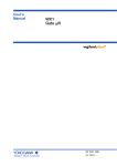
Handheld Digital
Thermometer
DP-700
Instruction Manual
®
RKC INSTRUMENT INC.
IMR01X01-E3
Microsoft, Windows, Excel are the registered trademark of Microsoft Corporation.
Company names and product names used in this manual are the trademarks or registered trademarks of
the respective companies.
All Rights Reserved, Copyright 2003, RKC INSTRUMENT INC.
Thank you for purchasing this RKC product. In order to achieve maximum performance and
ensure proper operation of your new instrument, carefully read all the instructions in this
manual. Please place the manual in a convenient location for easy reference.
SYMBOLS
WARNING : This mark indicates precautions that must be taken if there is danger of
electric shock, fire, etc., which could result in loss of life or injury.
CAUTION
!
: This mark indicates that if these precautions and operating procedures
are not taken, damage to the instrument may result.
: This mark indicates that all precautions should be taken for safe usage.
: This mark indicates important information on installation, handling and operating
procedures.
: This mark indicates supplemental information on installation, handling and
operating procedures.
: This mark indicates where additional information may be located.
!
WARNING
Never use this product for medical equipment.
This product must be used in accordance with the specifications
to prevent fire or damage to instrument and equipment.
This product is not intended for use in locations subject to
flammable or explosive gases.
If any abnormality such as smoke, smell of burning or noise was
found, do not use the product. If so, fire may occur.
RKC is not responsible if this product is repaired, modified or
disassembled by other than factory-approved personnel.
Malfunction can occur and warranty is void under these
conditions.
IMR01X01-E3
i-1
CAUTION
All precautions described in this manual should be taken to avoid damage to the
instrument or equipment.
Prevent metal fragments or lead wire scraps from falling inside instrument case to
avoid electric shock, fire or malfunction.
Do not drop nor apply strong impact to the product. If so, failure may result.
Do not use the product while the battery cover is being removed. If so, failure may
result.
Load a battery so that its polarity will meet the indication on the product. If not, the
battery electrolyte may leak or heat be generated to result in injury or failure.
If the product is not used for a long period of time, remove the battery from the
mainframe. If not, the battery electrolyte may leak to result in failure.
Battery service life may change depending on battery performance, operating
condition and measuring environment.
Use this product within the following ambient temperature and ambient humidity.
- Allowable ambient temperature: 20 to 50 C
- Allowable ambient humidity: 5 to 95 %RH
(Absolute humidity: MAX.W.C 29.3 g/m3 dry air at 101.3 kPa)
Do not use or store the product in places such as listed below:
- Rapid changes in ambient temperature which may cause condensation.
- Corrosive or inflammable gases.
- Direct vibration or shock to the mainframe.
- Direct water, oil, chemicals, vapor or steam splashes. *
- Excessive dust, salt or iron particles. *
- Excessive induction noise, static electricity, magnetic fields or noise.
- Direct air flow from an air conditioner.
- Exposure to direct sunlight.
- Excessive heat accumulation.
* DP-700A: Equal to IP67, DP-700B: Equal to IP54
Turn off the power supply before cleaning the instrument.
Do not use a volatile solvent such as paint thinner to clean the instrument.
Deformation or discoloration will occur. Use a soft, dry cloth to remove stains from
the instrument.
To avoid damage to instrument display, do not rub with an abrasive material or
push front panel with a hard object.
NOTICE
This manual assumes that the reader has a fundamental knowledge of the principles of
electricity, process control, computer technology and communications.
The figures, diagrams and numeric values used in this manual are only for purpose of
illustration.
RKC is not responsible for any damage or injury that is caused as a result of using this
instrument, instrument failure or indirect damage.
RKC is not responsible for any damage and/or injury resulting from the use of instruments
made by imitating this instrument.
Periodic maintenance is required for safe and proper operation of this instrument. Some
components have a limited service life, or characteristics that change over time.
Every effort has been made to ensure accuracy of all information contained herein. RKC
makes no warranty expressed or implied, with respect to the accuracy of the information.
The information in this manual is subject to change without prior notice.
No portion of this document may be reprinted, modified, copied, transmitted, digitized,
stored, processed or retrieved through any mechanical, electronic, optical or other means
without prior written approval from RKC.
i-2
IMR01X01-E3
CONTENTS
Page
1. OUTLINE .............................................................................. 1
1.1 Checking the Product ...................................................................................... 1
1.2 Parts Description ............................................................................................. 2
1.3 LCD Displays ................................................................................................... 3
1.4 Function Menu Configuration........................................................................... 4
2. PREPARATION BEFORE USE ............................................ 5
2.1 Loading Battery............................................................................................... 5
2.2 Setting Date and Time .................................................................................... 6
2.3 Connecting the Temperature Sensor .............................................................. 7
3. BASIC OPERATION ............................................................. 8
3.1 Turn Power On ................................................................................................ 8
3.2 Measuring Temperatures................................................................................. 9
4. JUDGING MEASURED TEMPERATURES [SIMPLIFIED
JUDGING FUNCTION] ....................................................... 10
4.1 Registering Tag Names (Measured Objects)................................................. 11
4.2 Setting the Judgment Range of High/Low Limit Temperatures...................... 14
4.3 Judging Measured Temperatures .................................................................. 15
5. RECORDING MEASURED TEMPERATURES
[LOGGING FUNCTION] ..................................................... 17
5.1 Manual Recording ......................................................................................... 18
5.2 Automatic Recording ..................................................................................... 19
5.3 Retrieving Recorded Data ............................................................................. 21
5.3.1 Retrieving only recorded data with specified tag name (Tag Filter) ................... 21
5.3.2 Retrieving recorded data with specified log registered No. (Log Jump) ............. 22
5.4 Deleting Recorded Data ................................................................................ 23
5.4.1 Deleting only one recorded data item (Delete?) ................................................. 23
5.4.2 Deleting all recorded data items (All Clear?) ...................................................... 24
5.5 Defragmenting Recorded Data ...................................................................... 25
6. PEAK HOLD/BOTTOM HOLD ........................................... 26
IMR01X01-E3
i-3
Page
7. REGISTERING USER NAMES [ONLY FOR DP-700B] ..... 28
8. INITIAL SETTING ............................................................... 32
To select the display language (English/Japanese) ....................................... 32
To select the date format ............................................................................... 32
To select the sensor type ............................................................................... 33
To select the display unit (C/F) .................................................................... 33
To select the decimal point position ............................................................... 34
To correct the temperature display value (PV Bias) ....................................... 34
To lessen the fluctuation of a display value caused by noise (Digital Filter) ... 35
Saving battery consumption (Auto Power OFF) ............................................. 35
Locking/Unlocking setting operation (Operation Lock) ................................... 36
9. MANAGING DATA BY PC [ONLY FOR DP-700B] ............ 37
9.1 Connecting PC to DP-700B ........................................................................... 37
9.2 Storing Data................................................................................................... 38
9.3 Disconnecting DP-700B from PC .................................................................. 41
10. APPENDIX ........................................................................ 42
10.1 Replace the Battery ..................................................................................... 42
10.2 Cleaning ...................................................................................................... 44
10.3 Troubleshooting ........................................................................................... 44
10.3.1 Error displays ................................................................................................... 44
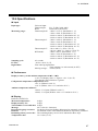
10.3.2 Problem and solution ....................................................................................... 46
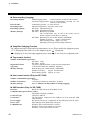
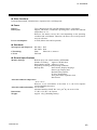
10.4 Specifications .............................................................................................. 47
i-4
IMR01X01-E3
1. OUTLINE
This Chapter describes features, package contents and model code, etc. The handheld digital
thermometer DP-700 has the following features:
Wide temperature measurement is possible
Thermocouple K: 200 to 1372 C (328 to 2501 F), 199.9 to 999.9 C (F)
Thermocouple J: 200 to 1200 C (328 to 2192 F), 199.9 to 999.9 C (F)
Thermocouple T: 50 to 400 C (58 to 752 F), 50.0 to 400.0 C (58.0 to 752.0 F)
RTD (Pt100):
200 to 850 C (328 to 1562 F), 199.9 to 850.0 C (199.9 to 999.9 F)
Names of measured objects can be registered.
Names of measured objects can be registered using 11 characters maximum.
(DP-700A: maximum 5 tags DP-700B: maximum 99 tags)
Simplified Judging Function
Judgment can be immediately made for each measured object. (Temperatures to judge the
high/low limits need to be set.)
Logging Function (Manual logging mode, Automatic logging mode)
Measured object, measured temperature, date, and user name can be manually or automatically
recorded in the memory. (DP-700A: maximum 99 logs DP-700B: maximum 9999 logs)
Peak and Bottom Hold Function
The maximum and minimum measured-temperatures can always be stored.
Can be operated for 400 hours continuously using one Type LR6 (based on
IEC and JIS) alkaline battery.
Data can be controlled using personal computers (Only for the DP-700B)
Measured data can be stored in the file in the CSV format using the USB port of each personal
computer.
1.1 Checking the Product
Before using this product, check each of the following:
Model code
Check that there are no scratch or breakage in external appearance.
Check that all of the items delivered are complete. (Refer to below)
Model code
DP-700 /
(1) (2)
(1) Type
A: Economy type
(No USB, Logging: 99 logs, Backed up by SRAM)
B: High performance type
(2) Display language
J: Japanese
E: English
(With USB, Logging: 9999 logs, Backed up by EEPROM)
Accessories:
Instruction Manual (IMR01X01-E3) ··· 1
Strap ·········································· 1
LR6 (IEC and JIS) Alkaline battery ············ 1
USB cable (Only for DP-700B) ··············· 1
If any of the products are missing, damaged, or if your manual is incomplete, please
contact RKC sales office or the agent.
IMR01X01-E3
1
1. OUTLINE
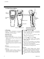
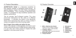
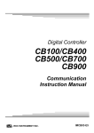
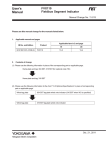
1.2 Parts Description
DP-700
LCD
display
USB connecter
(Only for DP-700B)
REC
Hooks for
carrying the
sensor
T
ES
C
SE
Operation
keys
MENU
/POWER
Battery cover
Strap hole
Sensor connection jack
LCD display
Displays various information on measured
temperature, measured date, set details of
each function and error number.
Operation keys
MENU/POWER key:
Used to turn on/off the power. Pressing
this key for more than 2 seconds can turn
off the power.
Can call up or select the function menu
screen while the power is turned on.
Can display the list of characters in the
message column while characters are being
entered.
SET key:
Establishes operation during execution.
ESC key:
Suspends operation during execution. If
suspended, returns to the displayed state or
screen just before being suspended.
2
Sensors that can be attached
to the hook are sold separately.
UP key (
)/DOWN key (
):
Can select measured objects or user names
already registered while the measurement
screen is being displayed.
Can select the list of characters while
characters are being entered.
Left shift key ()/Right shift key ():
Can select display details in the message
column while the measurement screen is
being displayed.
Can move to the preceding or next function
menu screen while the function menu (Fn0
to Fn9) screen is being displayed.
Can move the cursor character by character
while characters are being entered.
REC key:
When in manual logging mode (manual
recording), records the measured temperature
and date at the time when this key is pressed.
When in automatic logging mode (automatic
recording), used as a recording START/STOP
key.
IMR01X01-E3
1. OUTLINE
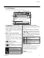
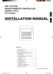
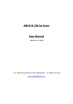
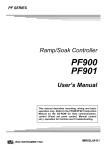
1.3 LCD Displays
The following details are displayed on the LCD screen.
(1)
(2)
(3)
(4)
C
(7)
(5)
(6)
このエリアは使用し
ません。
(8)
(9)
(1)
(Number display)
If measured object or user name is displayed,
displays the corresponding registered number.
When recorded data items are displayed,
displays “Display memory number/Total
memory number of recorded data items of
those data items.
(2)
(Log execution display)
When in manual logging mode (manual
recording), displayed only when the REC
key is pressed.
When in automatic logging mode (automatic
recording), continues lighting during
recording and continues flashing during
recording stop.
(5) Measured temperature display
Displays the measured temperature. In addition,
displays information on error number, etc. if an
error occurs.
(6) C or F (Temperature unit display)
(7)
(Simplified judgment display)
Symbols to judged the measured temperature. To
judge the measured temperature using these
symbols, it is necessary to set the judgment
points of its high and low limits.
Measured temperature exceeds
NG judgment point of high limit
temperature.
Measured temperature is within
OK judgment points.
Measured temperature is below
NG judgment point of low limit
temperature.
(3)
(Burnout display)
Displayed when the sensor is broken, shorted
or imperfectly connected.
(4)
(Remaining battery service life display)
Displays the remaining battery service life
(reference only).
(8) Message column
Displays function menu screen name, measured
date 1, measured object 3, user name 2, 3 etc.
1
Service life remains long.
Service life is going to shorten.
Service life is going to expire.
(Battery replacement is required.)
Service life has expired. (Immediate
battery replacement is required.)
IMR01X01-E3
Set the measured date, if necessary. (Refer to P. 6)
Not displayed if no user name is registered.
3
Number of registered characters: 11 maximum
2
(9)
,
Displays message selection.
3
1. OUTLINE
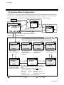
1.4 Function Menu Configuration
The DP-700 is provided with a function menu used to select and then set any function
necessary for measured-temperature judgment and recording (logging). There for, set the
desired function as needed by the customer. For details, refer to the relevant pages.
Power ON
User No.
When user name is
registered.
Measurement
screen
key
C
key
C
SET key
Tag No.
Dick
key
key,
01/01 00:00
key or
C
key
key
FRY1
ESC key or key
This symbol is always displayed.
ESC key
MENU/POWER key
Function Memu
Fn0 to Fn8 are menus which are not necessary to be used when
only temperatures are measured such as by a thermometer.
(P. 17)
(P. 10)
(P. 19)
Memory
TAG Setup
Logging
Menu used to check and
retrieve recorded
measured-temperatures.
Menu used to register
measured-object names,
and to set judging
conditions of measured
temperatures.
Menu used to set time
intervals of automatically
recording measuredtemperatures.
(P. 6)
(P. 32)
(P. 26)
Peak/Bottom
Menu used to check
maximum/minimum
measured-temperatures.
(P. 28)
Utility
Setup
UserName
Menu used to set
dominical year/month/
day/time and to check
information on versions.
Menu used to set items relating to initicalizeing setting.
If unnecessary to be changed, use their factory set
values.
Menu used to register
user names.
Initial setting items (factory set value):
P. 32
Display language: English
PV bias:
0.0 C
Date format:
month/day
Digital filter:
OFF
Sensor type:
TC-K
Auto power OFF: 3 min.
Display unit:
C
Operation lock: 0000 (Unlock)
Decimal point position: 0.1 (One dicimal place)
: Press the MENU/POWER key or key
4
: Press the key
IMR01X01-E3
2. PREPARATION BEFORE USE
This chapter describes preparations necessary for operating this instrument for the first time.
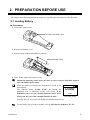
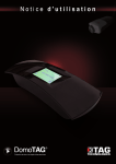
2.1 Loading Battery
Procedures
1. Loosen the battery cover.
Turn the cover with a coin.
2. Remove the battery cover.
3. Load a battery without mistaking its polarity.
Alkaline battery (LR6)
4. Then, firmly tighten the battery cover.
Insufficient tightening cannot assure the effect of water resistance (DP-700A: Equal to
IP67, DP-700B: Equal to IP54).
After the battery is loaded, the instrument is ready to be
reset-started.
The function menu “Utility (Fn0)” for setting the
dominical year is displayed on the LCD screen. If no
dominical year is set, no calendar function can be used.
Always set the year if the calendar function is used.
Year
Year setting screen
Pressing the ESC key twice can display the measurement screen.
For the battery life or replace method, refer to 10.1 Replace the Battery (P. 42).
IMR01X01-E3
5
2. PREPARATION BEFORE USE
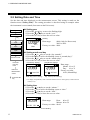
2.2 Setting Date and Time
Set the date and time displayed on the measurement screen. This setting is made on the
function menu “Utility (Fn0).” The setting procedure is described using an example where
the instrument is reset-started (from start on the Fn0 screen).
Battery setting
Reset start
Automatically
Setting year
1. Press the or key to move the flashing digit.
2. Press the or key to set the “year.”
3. Press the SET key to store the new set value.
Flashing
Data range:
0000 (Only for Reset start)
2003 to 9999
Factory set value: 0000
Year
Date
Year
Time
ROM version
Return to Year
Press the
ESC key
twice
Returns to
Measurement
screen
: Press the SET
key
Setting month and day
1. Press the or key to set the “day (month).”
2. Press the key to move the blinking cursor to “month (day).”
3. Press the or key to set the “month (day).”
4. Press the SET key to store the new set value.
(“Month/Day” display)
(“Day/Month” display) *
01/01 m m / d d
01/01 d d / m m
Month Day (Cursor blinking)
Data range:
Month: 01 to 12
Day:
01 to 31
Factory set value:
01/01 (Month/Day)
Day Month (Cursor blinking)
* To display “Day/Month,” refer to the date format screen in “Setup (Fn9)” of the Function
menu (P. 32).
Setting time
1. Press the or key to set the “minute.”
2. Press the key to move the blinking cursor to “time.”
3. Press the or key to set the “time.”
4. Press the SET key to store the new set value.
Data range:
01/01 00:00
Hour: 00 to 23
Minute: 00 to 59
Factory set value: 00:00
Cursor blinking
6
IMR01X01-E3
2. PREPARATION BEFORE USE
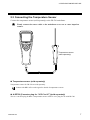
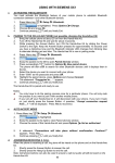
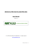
2.3 Connecting the Temperature Sensor
Connect the temperature sensor (sold separately) to the DP-700 mainframe.
Firmly connect the sensor cable to the mainframe so as not to cause imperfect
contact.
DP-700
REC
T
ES
C
SE
MENU
/POWER
Temperature sensor
(sold separately)
Temperature sensor (sold separately)
Temperature sensors for DP-700 are sold separately.
Contact with RKC office or the agent for details of temperature sensors.
A-DP700 [Converter plug for “3C/2C to 6C”] (sold separately)
This is a converter plug for RKC’s temperature sensors with 3C or 2C plug for use with DP-700.
IMR01X01-E3
7
3. BASIC OPERATION
This chapter describes the basic operation of the instrument for temperature measurement.
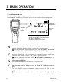
3.1 Turn Power On
Press the MENU/POWER key. The power is turned on to display the measurement screen.
DP-700
C
REC
T
ES
C
SE
MENU
/POWER
Simplified
judgment
display
Measured
temperature
Date and
Time *
11/11 09:00
* If the data and time are not set in the
function menu [Utility (Fn0)], the factory
set value is displayed.
[Factory set value: 01/01 00:00]
When the power is turned on for the first time after preparations before operation are
finished, “Simplified judgment display” is as the above screen example.
For the simplified judgment display, refer to 4. JUDGING MEASURED
TEMPERATURES [SIMPLIFIED JUDGING FUNCTION] (P. 10).
The power is turned off if no key operation is performed for more than the Auto
power OFF time (factory set value: 3 min.) with the power turned on.
For the Auto power OFF setting, refer to Saving battery consumption (P. 35).
How to power off DP-700?
Press and hold the MENU/POWER key for 2 seconds or more.
What screen is displayed when the power is turned off and then is turned on
again?
If the user name is registered to the user number selected, the type of screen
displayed first differs.
For the type of screen displayed, refer to 1.4 Function Menu Configuration (P. 4).
8
IMR01X01-E3
3. BASIC OPERATION
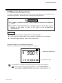
3.2 Measuring Temperatures
To measure temperatures, insert the sensor into or contact it with the measured object. When
measuring temperatures, handle the sensor as instructed in the following.
!
WARNING
In order to prevent injuries, never direct the sensor tip toward a
person.
In order to prevent burning or frostbite, do not touch the sensor
during or just after its use in the high or low temperature
environment.
CAUTION
Use the sensor within its temperature measuring range.
Firmly insert the sensor cable into the sensor connector of the mainframe.
If the sensor gets stained, wipe it with a clean cloth.
Example of display screen during measurement:
When a measured object is at a surface temperature of 90.0 C
C
11/11 09:05
Measured temperature
Measured date
It is possible to record the measured temperature and date in the memory.
For the data recording (logging) method, refer to 5. RECORDING
MEASURED TEMPERATURES [LOGGING FUNCTION] (P. 17).
IMR01X01-E3
9
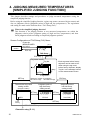
4. JUDGING MEASURED TEMPERATURES
[SIMPLIFIED JUDGING FUNCTION]
This chapter describes settings and procedures to judge measured temperatures using the
simplified judging function.
Before using the simplified judging function, register tag names (measured object names) and
also set judgment criteria (judgment points of high and low temperatures). The registration
and setting are made on the function menu “TAG Setup (Fn2).”
What is the simplified judging function?
This function is for judging whether or not measured temperatures are within the
judgment criteria preset (judgment points of high and low temperatures) and then
check judgment results according to simplified judgment symbols.
Screen Configurations of TAG Setup (Fn2) Menu:
Measurement
screen
Press the
MENU/POWER
key twice
(P. 4)
ESC key
TAG Setup
ESC key
SET key
Tag name screen
Tag No.
key
key
TAG01
* Each tag name before factory
shipment can be used as it is.
When using the tag name
before factory shipment, display
Tag No. in the message column
on the measurement screen.
Tag name *
SET key
Maximum number of registration
DP-700A: 5 tags
DP-700B: 99 tags
The selected tag name
setting screen
(Example: TAG01)
Judgment point of
high limit temp.
setting screen
SET key
C
Judgment point of
low limit temp.
setting screen
SET key
Hi Limit
TAG01
(P. 11)
Cursor
blinking
ESC key
C
Low Limit
(P. 14)
(P. 14)
SET key
MENU/POWER key
Character entry (P. 11)
10
IMR01X01-E3
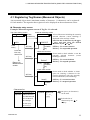
4. JUDGING MEASURED TEMPERATURES [SIMPLIFIED JUDGING FUNCTION]
4.1 Registering Tag Names (Measured Objects)
Any measured object mane (maximum number of character: 11 characters) can be registered
for each number. The tag name thus registered can be displayed on the measurement screen.
Character entry screen
Example: When the tag name screen of Tag No. 1 is selected.
Tag name setting screen
Character selecting screen
MENU/
POWER key
STUVWXYZ
TAG01
Cursor
blinking
MENU/
POWER
key
SET key
ESC key
Press the
ESC key
three times
A list of characters including the currently
selected character (cursor blinking) is
displayed in the message column.
Select the list of characters by the
or
key and then select the desired
character by the or key.
SET key: To execute selection
ESC key: To suspended operation
Delete check screen
Screen used to check whether or not the
currently selected character (cursor
blinking) is deleted.
SET key
ESC key
Delete?
Returns to
Measurement
screen
(P. 13)
SET key: To execute deletion
ESC key: To suspend operation
MENU/
POWER
key
Insert check screen
Screen used to check whether to insert
space for entering a character in the
position displayed with the currently
selected character (cursor blinking).
SET key
ESC key
Insert?
(P. 13)
MENU/
POWER
key
SET key: To execute insertion
ESC key: To suspend operation
Characters list
Numerals
0123456789
Alphabets A B C D E F G H I
JKLMNOPQR
STUVWXYZ
abcdefghi
jklmnopqr
stuvwxyz
IMR01X01-E3
Symbols
@!#$%&’`
+-.;=^_
()[]{}
No spaces (no characters)
can be used.
Select the list of
characters by the
key.
or
11
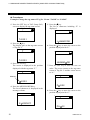
4. JUDGING MEASURED TEMPERATURES [SIMPLIFIED JUDGING FUNCTION]
Procedures
Example: Change the tag name of Tag No. 2 from “TAG02” to “PAN02”
1. Press the SET key at TAG Setup (Fn2)
screen to display the tag name screen.
5. Press the key.
The list of characters including “P” is
displayed.
TAG01
JKLMNOPQR
2. Press the key.
The display goes to the tag name screen
of Tag No. 2.
6. Press the key to move the cursor to the
position displayed with “P.”
TAG02
3. Press the SET key.
The cursor is displayed in the position
displayed with the tag name “T.”
JKLMNOPQR
7. Press the SET key to store the new set
value. The screen returns to the tag name
screen of Tag No. 2 and the cursor moves
to “A.”
Blinking
TAG02
4. Press the MENU/POWER key.
The list of characters is displayed in the
message column.
PAG02
8. Press the key to move the cursor to the
position displayed with “G.”
STUVWXYZ
PAG02
12
IMR01X01-E3
4. JUDGING MEASURED TEMPERATURES [SIMPLIFIED JUDGING FUNCTION]
9. Press the MENU/POWER key.
The list of characters is displayed in the
message column.
When setting the judgment criteria
(judgment points of high and low
temperatures) succeedingly, press the SET
key. (P. 14)
To return to the measurement screen,
press the ESC key three times.
ABCDEFGHI
10. Press the
key.
The list of characters including “N” is
displayed.
How to change the character without
displaying the list of characters?
1. Move the cursor to the position displayed
with the character to be revised by using
the or key.
2. Display the character to be revised by
using the or key.
JKLMNOPQR
11. Press the key to move the cursor to the
position displayed with “N.”
How to delete one character?
1. Move the cursor to the position displayed
with the character to be deleted using the
or key.
2. Press the MENU/POWER key twice to
display the screen for checking the deletion.
3. Press the SET key to delete the character
where the cursor blinked.
JKLMNOPQR
12. Press the SET key to store the new set
value. The screen returns to the tag name
screen of Tag No. 2 and the cursor moves
to “0.”
How to insert space for entering a
character in any position?
1. Move the cursor to the position where a
character needs to be entered using the
or key.
2. Press the MENU/POWER key three times
to display the screen for checking the
entry.
PAN02
3. Press the SET key to insert space for
entering the character before the character
position where the cursor blinks.
The setting is finished.
IMR01X01-E3
13
4. JUDGING MEASURED TEMPERATURES [SIMPLIFIED JUDGING FUNCTION]
4.2 Setting the Judgment Range of High/Low Limit Temperatures
Set the judgment points of high and low temperatures for judging measured temperatures.
This setting is made for each tag name. This judgment is conducted from the time when
measurement is started.
Procedures
Example: When setting a high temperature of 90.0 C and a low temperature of 50.0 C
for Tag No. 2 (tag name: PAN02)
1. Press the SET key at the tag name screen
of Tag No. 2 to display the judgment
point of high limit temperature setting
screen.
4. Press the SET key to store the new value.
The display goes to the next screen
(Judgment point of low limit temperature).
Flashing
Flashing
C
C
Low Limit
Hi Limit
2. Press the key to flash the tens digits.
C
Setting range:
Same as input
range
C
Factory set
value:
0.0 C [32.0 F]
Hi Limit
3. Press the
“9.”
5. Press the key to flash the tens digits.
key to change the number to
Factory set
value:
0.0 C [32.0 F]
Low Limit
6. Press the
“5.”
Setting range:
Same as input
range
key to change the number to
C
C
Low Limit
Hi Limit
7. Press the SET key to store the new set
value. The display returns to the tag name
screen of Tag No. 2.
The setting is finished.
To return to the measurement screen after the setting is finished, press the ESC key three
times.
14
IMR01X01-E3
4. JUDGING MEASURED TEMPERATURES [SIMPLIFIED JUDGING FUNCTION]
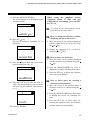
4.3 Judging Measured Temperatures
The judgment criteria of a measured temperature is described by referring to the following
example.
Measured object: Hot water
Tag number:
2 (tag name: PAN02)
Judgment criteria: Judgment point of high limit temperature 90.0 C
Judgment point of low limit temperature 50.0 C
Procedures
1. Turn on the power. The measurement screen appears on the LCD.
2. Press the key. Tag name is displayed in the message column.
First check whether or not a displayed screen is for the tag name of Tag No. 2. If not,
press the or key to select the tag name of Tag No. 2.
C
11/11 10:00
Measurement screen
C
C
TAG01
PAN02
Example:
Tag name screen of Tag
No. 1
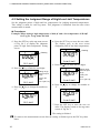
The tag name displayed when the key is pressed is that with the tag number
selected last, which continues to be displayed until the power is turned off.
For example, if the tag name of Tag No. 5 is selected last, the tag name of Tag No. 5
is displayed in the message column when selected to the tag name from the
measured date.
When the power is
turned off with the
tag name of Tag
No. 5 displayed.
Power ON
C
C
11/11 10:00
Measured date
TAG05
Tag name
Continued on the next page.
IMR01X01-E3
15
4. JUDGING MEASURED TEMPERATURES [SIMPLIFIED JUDGING FUNCTION]
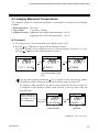
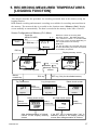
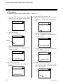
3. Temperatures in a measured object are measured.
When exceeding the judgment point (90.0 C) of high limit temperature
High limit temp.
Measured temp. (95.0 C)
C
Judgment range
Low limit temp.
Judgment symbol
PAN02
Tag name screen
When falling below the judgment point (50.0 C) of low limit temperature
High limit temp.
C
Judgment range
Measured temp. (45.0 C)
Low limit temp.
Judgment symbol
PAN02
Tag name screen
When within the judgment points (50.0 to 90.0 C)
High limit temp.
Judgment range
Low limit temp.
Measured temp. (80.0 C)
C
Judgment symbol
PAN02
Tag name screen
Thus, the judgment of measured temperatures has been finished.
When needing to record measured temperatures * in the memory,
refer to 5. RECORDING MEASURED TEMPERATURES
[LOGGING FUNCTION] (P. 17).
* No result of judgment can be recorded in the memory.
16
IMR01X01-E3
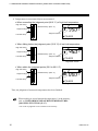
5. RECORDING MEASURED TEMPERATURES
[LOGGING FUNCTION]
This chapter describes the procedure for recording measured data in the memory using the
logging function.
Both manual recording and automatic recording are available for recording measured data in
the memory. The measured data is recorded on the function menu “Memory (Fn1)” display
screen manually or automatically. The data is recorded in the memory in the order of arrival.
Screen Configurations of Memory (Fn1) Menu:
Measurement
screen
Press the
MENU/POWER
key
Maximum number of recording data:
DP-700A: 99 logs DP-700B: 9999 logs
The maximum number of recorded data
items may not be recorded depending on
the occupied state in the memory.
Data hold:
For the DP-700A, the recorded data may
be lost if the battery service life has expired
or the battery is replaced.
(P. 4)
ESC key
Memory
SET key
ESC key
Display memory screen
key
C
C
key
key
key
TAG01
Recorded date
Log Jump screen
MENU/
POWER key
Delete check screen
MENU/
POWER key
TagFilter
Log Jump
(P. 21)
(P. 23)
All Clear check screen
Defrag check screen
C
C
Delete?
(P. 22)
MENU/
POWER key
key
SET key (Only for the shaded screen)
ESC key
Tag Filter screen
C
11/11 10:00
Message column
transfer
Recorded tag name
MENU/
POWER key
key
C
MENU/
POWER key
MENU/
POWER key
%
Defrag?
SET key
(P. 25)
After defragmentation is finished,
returns to the display memory
screen.
IMR01X01-E3
All Clear?
SET key
(P. 24)
If the SET key is pressed after “Yes” is
selected, returns to the display memory
screen after defragmentation is finished.
17
5. RECORDING MEASURED TEMPERATURES [LOGGING FUNCTION]
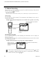
5.1 Manual Recording
Measured data * just when the REC key is pressed is recorded in the memory. Only when the
REC key is pressed,
is displayed.
* Recordable measured data:
Measured temperature, Measured date (excluding “Year”), Measured tag No. (tag name), Measured user No.
Recording
Press the REC key while measured. The measurement result displayed on the screen is
recorded in the memory.
Example: When measured temperatures are recorded on the tag name screen of Tag
No. 2
Only when the REC key is pressed,
is displayed.
DP-700
C
REC
T
ES
C
SE
M
E
No judgment result
is recorded.
PAN02
Display on the measurement
screen when the REC key is
pressed.
Checking of recording
Press the MENU/POWER key while displaying the measurement screen to display the
Memory (Fn1) screen.
Pressing the SET key displays the recorded measured-data memory screen to be able to check
the recorded measured-data.
Example: When the memory screen in the above example is displayed
Display memory No.:
Indicates in what memory
number measured data is
recorded.
C
Total number of recorded memory
data
PAN02
If two or more recorded data items need to be checked in order, press the or key.
It is possible to change the display (tag name or recorded date) in the message
column. If necessary, press the or key.
18
IMR01X01-E3
5. RECORDING MEASURED TEMPERATURES [LOGGING FUNCTION]
5.2 Automatic Recording
Measured data * is recorded in the memory at time intervals preset. For automatic
measured-data recording, the time interval needs to be set. Set it according to the following
procedure.
* Recordable measured data:
Measured temperature, Measured date (excluding “Year”), Measured tag No. (tag name), Measured user No.
Setting interval time
1. Press the MENU/POWER key three
times at the measurement screen to
display the function menu “Logging
(Fn3)” screen.
3. Set the interval time by the
key and
the shift key ( , ).
(Example: Interval time 15 seconds)
Sec
Flashing
Logging
Intervals
2. Press the SET key.
The display goes to the interval time
setting screen.
4. Press the SET key to store the new set
value. The display returns to the
Logging (Fn3) screen. If the interval
time is set,
flashes (recording
stop).
Sec
The setting finished.
Flashing
Intervals
Interval time:
Setting range:
OFF (Manual logging)
1 to 3600 seconds (Automatic logging)
Factory set value:
OFF (Manual logging)
IMR01X01-E3
To return to the measurement screen
after the setting is finished, press the
ESC key.
How to cancel the interval time
setting?
Press the ESC key. The display returns
to the Logging (Fn3) screen.
19
5. RECORDING MEASURED TEMPERATURES [LOGGING FUNCTION]
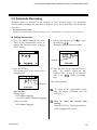
Recording
Press the REC key at the measurement screen. Recording starts at time intervals preset.
keeps lighting while being recorded.
Example: When automatic measured-temperature recording is started while the tag
name screen of Tag No. 2 is displayed.
Lighting (during recording)
DP-700
C
REC
T
ES
C
SE
M
E
No judgment result is
recorded.
PAN02
Display on the measurement
screen when the REC key is
pressed.
If the power is turned off by pressing the MENU/POWER key or even if the
power is turned off by the activation of the Auto power OFF function (P. 35),
during recording (
being lit) data recording continues at time intervals
preset.
Recording stop
Press the REC key.
flashes to stop data recording.
How to return to manual recording?
First, stop data recording and then turn the time interval to “OFF.”
For the interval time setting, refer to Setting interval time (P. 19).
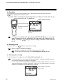
Checking of recording
To the checking of recording, refer to 5.1 Manual Recording (P. 18).
It is also possible to check recorded measured-data by opening the display memory
screen while automatic recording is being made.
As the measured data being checked is displayed on the display memory screen, no
measured data being recorded is displayed. In this case, the total number of recorded
memories is counted every time the data is recorded.
C
Total number of recorded
memory data
PAN02
Display memory screen
20
IMR01X01-E3
5. RECORDING MEASURED TEMPERATURES [LOGGING FUNCTION]
5.3 Retrieving Recorded Data
Measured data is recorded in the memory in the order of arrival. The following two types of
retrieval are available for checking any tag name and recorded measured-data recorded in the
memory. Use either one of them depending on your application.
Tag filter: Only measured data with any tag name is retrieved and then displayed.
Log jump: Recorded measured-data is displayed by specifying the display memory number.
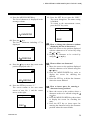
5.3.1 Retrieving only recorded data with specified tag name
(Tag Filter)
As measured data is recorded in the order of arrival, there may be a case where no data is
recorded for each tag name. It is possible to retrieve and then display only the measured data
with the specified tag name bay setting this tag filter.
Procedures
1. Press the MENU/POWER and SET keys
in this order while displaying the
measurement screen to display the
display memory screen.
4. Press the
key to change the item to
“ON.”
C
Flashing
TagFilter
TAG01
5. Press the SET key to store the new set
2. Press the
or
key while displaying
the display memory screen to display the
log name to be retrieved.
value. Returns to the display memory
screen with the log name to be retrieved.
C
C
TAG03
Log name
to be
retrieved
TAG03
6. Pressing the
3. Press the MENU/POWER key to display
the Tag Filter screen.
Flashing
TagFilter
IMR01X01-E3
or
key displays only
the display memory screen with the log
name retrieved. To return to the
measurement screen, press the SET key
twice.
How to release the log filter?
Change the log filter setting to “OFF” by
pressing the
key and then press the
SET key.
21
5. RECORDING MEASURED TEMPERATURES [LOGGING FUNCTION]
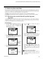
5.3.2 Retrieving recorded data with specified log registered No.
(Log Jump)
It is possible for the DP-700A to record up to 99 logs and for the DP-700B, up to 9999 logs,
respectively, For this reason, it is more difficult to select the display memory screen of data to
be checked as the number of recording data items increases. It is possible to retrieve and then
display any data with specified display memory number by setting this Log Jump.
Procedures
1. Press the MENU/POWER key and SET
key in this order while displaying the
measurement screen to display the
display memory screen.
4. Press the SET key.
Displays the screen with the display
memory number specified. To return to
the measurement screen, press the SET
key twice.
C
C
TAG01
TAG05
2. Press the MENU/POWER key twice to
display the Log Jump screen.
Current
display
memory No.
Log Jump
How to cancel the log jump?
Press the ESC key.
The display returns to the Logging
(Fn3) screen.
Flashing
3. Press the
key, key, or the shift key
( , ) to display the log name to be
retrieved.
Display
memory No.
to be
retrieved
Flashing
Log Jump
22
IMR01X01-E3
5. RECORDING MEASURED TEMPERATURES [LOGGING FUNCTION]
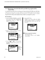
5.4 Deleting Recorded Data
The following two types of procedure are available for deleting measured data recorded in the
memory.
Deleted?:
Deletes only one recorded data item.
All data deleted?: Deleted all recorded data items.
5.4.1 Deleting only one recorded data item (Delete?)
Can delete only one recorded data item selected. If the procedure for this deletion is executed,
the display memory number and the total number of recorded data items decrease by one.
C
TAG01
C
TAG01
C
TAG01
C
TAG05
To delete
C
C
Delete
TAG01
TAG01
Procedures
1. Press the MENU/POWER key and SET
key in this order while displaying the
measurement screen to display the
display memory screen.
C
TAG05
3. Press the MENU/POWER key three times
to display the delete check screen.
C
C
Delete?
TAG01
2. Press the or key while displaying
the display memory screen to display the
screen to be deleted.
Display
memory No.
to be deleted
C
Haw to cancel “Delete?”
Press the ESC key.
The display returns to the display
memory screen.
4. Pressing
the SET key executes the
procedure for this deletion. The display
returns to the display memory screen. To
return to the measurement screen, press
the SET key twice.
TAG01
IMR01X01-E3
23
5. RECORDING MEASURED TEMPERATURES [LOGGING FUNCTION]
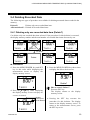
5.4.2 Deleting all recorded data items (All Clear?)
Can delete all recorded data items recorded.
Procedures
1. Press the MENU/POWER and SET keys
in this order while displaying the
measurement screen to display the
display memory screen.
C
TAG01
2. Press the MENU/POWER key four
times to display the All Clear check
screen.
4. Pressing the SET key executes the
procedure for this deletion (All Clear).
The following progress check screen is
displayed during the execution of this
deletion.
Do not press the key until this screen
automatically disappears.
Returns to the measurement screen after
the procedure for this deletion is
finished.
No deletion is suspended even it
the ESC key is pressed while the
procedure for this deletion is in
progress.
Flashing
All Clear?
3. Press the
“YES.”
key to change the item to
%
All Clear!
Deletion
progress
ratio (%)
This deletion is
finished.
Returns to the measurement screen
Flashing
All Clear?
How to cancel “YES”?
Press the ESC key.
The display returns to the display
memory screen.
To return to the measurement screen,
press the ESC key three times.
24
IMR01X01-E3
5. RECORDING MEASURED TEMPERATURES [LOGGING FUNCTION]
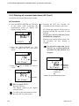
5.5 Defragmenting Recorded Data
If measured data recording and deleting operation are repeated, the recording memory
capacity may become insufficient. However, it becomes possible to efficiently secure the
recordable area by rearranging recorded data in the memory and defragmenting the memory
area.
Procedures
1. Press the MENU/POWER and SET keys
in this order while displaying the
measurement screen to display the
display memory screen.
C
TAG01
2. Press the MENU/POWER key five times
to display the defrag check screen.
Total
number of
recorded
memory
data
%
Defrag?
Memory
usage
ratio (%)
3. Pressing the SET key executes the
procedure for this defragmentation.
The following progress check screen is
displayed while defragmentation is
being executed. Time required for this
defragmentation differs depending of the
memory area being used.
Do not press the key until this screen
automatically disappears.
Returns to the display memory screen
after
the
procedure
for
this
defragmentation is finished.
%
Defrag!
Defragmentation
progress ratio
(%)
This defragmentation
is finished.
Returns to the display memory screen
How to cancel the procedure for
this defragmentation?
Press the ESC key.
The display returns to the display
memory screen. To return to the
measurement screen, press the ESC
key twice.
IMR01X01-E3
To return to the measurement screen,
press the ESC key twice.
The defragmentation is possible
even during automatic recording. In
addition,
automatic
recording
continues after the defragmentation
is finished.
25
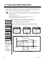
6. PEAK HOLD/BOTTOM HOLD
The peak hold/bottom hold function is used to store (hold) the maximum (peak) and minimum
(bottom) measured temperature. Each of these values is updated when the measured
temperature becomes more (or less) than the value now being held.
However, if the following operation is performed, the value now being held is reset
and as a result the measured temperature just when reset becomes the peak hold or
bottom hold value.
When replaced the battery.
When changed sensor type, display unit or decimal point position
When reset (peak/bottom) by the key operation
Power ON
Automatically
Measurement
To display the peak hold value/bottom hold value
1. Press the SET key at Peak/Bottom (Fn4) screen.
The display goes to Peak hold value screen.
2. Press the SET key. The display goes to Bottom hold value screen.
3. Press the SET key. The display returns to Peak hold value screen.
Memory (Fn1)
Peak/Bottom (Fn4)
Peak hold value
TAG Setup
(Fn2)
C
SET
Logging (Fn3)
Peak/Bottom
(Fn4)
Peak/Bottom
Peak val.
Bottom hold value
SET
SET
C
Bottom val.
ESC
ESC
User Name
(Fn8)
Setup (Fn9)
Measured temperature (PV)
Temperature display value
(Peak hold value)
Utility (Fn0)
PV
Returns to
Memory (Fn1)
screen
ESC key
Returns to
Measurement
screen
: Press the
MENU/POWER
key or key
Temperature display
value
(Bottom hold value)
Time
Power ON
Bottom hold Peak hold
value
value
display
display
updating
updating
Peak reset
(Refer to P. 27)
Peak/bottom hold action description
26
IMR01X01-E3
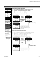
6. PEAK HOLD/BOTTOM HOLD
Power ON
Automatically
Measurement
Memory (Fn1)
TAG Setup
(Fn2)
To reset the peak hold value
1. Press the MENU/POWER key at Peak hold value screen.
2. “Peak rst?” is displayed in the message column.
To execute reset: Press the SET key.
To cancel reset: Press the ESC key.
3. The display returns to Peak hold value screen.
Peak hold value
MENU/
C
Logging (Fn3)
Peak/Bottom
(Fn4)
User Name
(Fn8)
Returns to
Memory (Fn1)
screen
ESC key
Returns to
Measurement
screen
: Press the
MENU/POWER
key or key
POWER
ESC
(To cancel
reset)
Peak val.
Peak hold value
C
Peak rst?
SET
(To execute reset)
C
Setup (Fn9)
Utility (Fn0)
Peak reset
Peak hold value becomes
measured temperature just
when reset.
Peak val.
To reset the bottom hold value
1. Press the MENU/POWER key at Bottom hold value screen.
2. “Bottom rst?” is displayed in the message column.
To execute reset: Press the SET key.
To cancel reset: Press the ESC key.
3. The display returns to Bottom hold value screen.
Bottom hold value
Bottom reset
MENU/
C
Bottom val.
Bottom hold value
POWER
ESC
(To cancel
reset)
C
Bottom rst?
SET
(To execute reset)
C
Bottom val.
IMR01X01-E3
Bottom hold value becomes
measured temperature just
when reset.
27
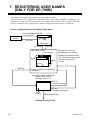
7. REGISTERING USER NAMES
[ONLY FOR DP-700B]
This chapter describes the procedure for registering user name.
Any user name can be registered (11 characters max.) for each user number. In addition, it is
possible to set the user by selecting the user number. The user thus set is retained until the
power is turned off. The registered user name is displayed when the power is turned on.
Screen configurations of User Name (Fn8) menu:
Press the MENU/POWER
key five times.
(P. 4)
Measurement
screen
ESC key
UserName
ESC key
SET key
User name screen
User number
Key
Key
SET key
The user can be set by
selecting the user number.
* Nothing is registered at the
time of factory shipment and
therefore this space is
vacant.
User name *
Number of maximum registration:
99 names
User name setting screen with
selected user number
(Example: User No. 1)
SET key
(To execute setting)
(P. 29)
Cursor
blinking
ESC key
(To suspend operation)
MENU/POWER key
Character entry (P. 29)
28
IMR01X01-E3
7. REGISTERING USER NAMES [ONLY FOR DP-700B]
Character entry screen
Example: When the user name screen of user No. 1 is selected.
User name setting screen
Character selecting screen
MENU/
POWER key
0123456789
Cursor
blinking
MENU/
POWER
key
SET key
ESC key
A list of characters including the currently
selected character (cursor blinking) is
displayed in the message column.
Select the list of characters by the
or
key and then select the desired
character by the or key.
SET key: To execute selection
ESC key: To suspended operation
Delete check screen
Press the
ESC key
three times
Screen used to check whether or not the
currently selected character (cursor
blinking) is deleted.
SET key
ESC key
Delete?
Returns to
Measurement
screen
(P. 31)
SET key: To execute deletion
ESC key: To suspend operation
MENU/
POWER
key
Insert check screen
Screen used to check whether to insert
space for entering a character in the
position displayed with the currently
selected character (cursor blinking).
SET key
ESC key
Insert?
(P. 31)
MENU/
POWER
key
SET key: To execute insertion
ESC key: To suspend operation
Characters list
Numerals
0123456789
Alphabets A B C D E F G H I
JKLMNOPQR
STUVWXYZ
abcdefghi
jklmnopqr
stuvwxyz
IMR01X01-E3
Symbols @ ! # $ % & ’ `
+-.;=^_
()[]{}
No spaces (no characters)
can be used.
Select the list of
characters by the
key.
or
29
7. REGISTERING USER NAMES [ONLY FOR DP-700B]
Procedures
Example: Registers the user name “RKC” to user No. 1.
1. Press the SET key at User Name menu
(Fn8) screen. The display goes to user
name screen of user No. 1.
5. Press the SET key to store “R.”
The screen returns to the user name screen
of user No. 1 and the cursor moves to the
right.
R
2. Press the SET key.
The cursor is displayed
6. Press the MENU/POWER key.
The list of characters is displayed in the
message column.
Blinking
JKLMNOPQR
3. Press the MENU/POWER key.
The list of characters is displayed in the
message column.
7.
0123456789
4. Press the key twice.
The list of characters including “R” is
displayed.
Press the key to move the cursor to the
position displayed with “K.”
JKLMNOPQR
8.
Press the SET key to store “K.”
The screen returns to the user name
screen of user No. 1 and the cursor
moves to the right.
JKLMNOPQR
RK
30
IMR01X01-E3
7. REGISTERING USER NAMES [ONLY FOR DP-700B]
9. Press the MENU/POWER key.
The list of characters is displayed in the
message column.
13. Press the SET key to store the “RKC.”
The cursor disappears. The name setting
is finished.
To return to the measurement screen,
press the ESC key twice.
JKLMNOPQR
10. Press the key.
The list of characters including “C” is
displayed.
ABCDEFGHI
11. Press the key to move the cursor to the
position displayed with “C.”
ABCDEFGHI
12. Press the SET key to store “C.”
The screen returns to the user name
screen of user No. 1 and the cursor
moves to the right.
RKC
IMR01X01-E3
RKC
How to change the character without
displaying the list of characters?
1. Move the cursor to the position displayed
with the character to be revised by using
the or key.
2. Display the character to be revised by
using the or key.
How to delete one character?
1. Move the cursor to the position displayed
with the character to be deleted using the
or key.
2. Press the MENU/POWER key twice to
display the screen for checking the
deletion.
3. Press the SET key to delete the character
where the cursor blinked.
How to insert space for entering a
character in any position?
1. Move the cursor to the position where a
character needs to be entered using the
or key.
2. Press the MENU/POWER key three times
to display the screen for checking the
entry.
3. Press the SET key to insert space for
entering the character before the character
position where the cursor blinks.
31
8. INITIAL SETTING
This chapter introduces each function which can be set according to the customer applications.
For items that are not necessary to be changed, use the same setting values as the factory
set values.
Power ON
Automatically
Measurement
Press the
MENU/POWER
key or key six
times
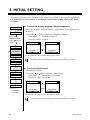
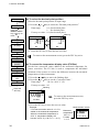
To select the display language (English/Japanese)
Select the language (English/Japanese) which needs to be displayed on
the screen.
1. Press the or key to select the “English or Japanese.”
Data range:
English or Japanese
Factory set value: English
Setup (Fn9)
Display
language
Date format
Sensor type
English
Japanese
2. Press the SET key to store the new set value.
To return to the measurement screen, press the ESC key twice.
Display unit
Decimal point
position
PV Bias
Digital filter
To select the date format
Select the date format.
1. Press the or key to select the “Date format.”
Data range:
month/day or day/month
Factory set value: month/day
Auto power
OFF
Operation lock
: Press the
month/day
day/month
SET key
2. Press the SET key to store the new set value.
To return to the measurement screen, press the ESC key twice.
32
IMR01X01-E3
8. INITIAL SETTING
Power ON
Automatically
Measurement
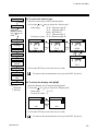
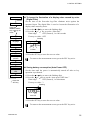
To select the sensor type
Select the sensor type used for measurement.
1. Press the or key to select the “Sensor type.”
Data range:
Press the
MENU/POWER
key or key six
times
TC-K: Thermocouple K
TC-J: Thermocouple J
Pt100: RTD Pt100
TC-T: Thermocouple T
Factory set value: TC-K (Thermocouple K)
Setup (Fn9)
Display
language
Date format
TC-K
TC-J
Pt100
Sensor type
Display unit
Decimal point
position
PV Bias
Digital filter
TC-T
2. Press the SET key to store the new set value.
To return to the measurement screen, press the ESC key twice.
Auto power
OFF
Operation lock
: Press the
SET key
To select the display unit (C/F)
Select the display unit of measured temperature.
1. Press the or key to select the “Display unit.”
Data range:
C or F
Factory set value: C
C
Unit
F
Unit
2. Press the SET key to store the new set value.
To return to the measurement screen, press the ESC key twice.
IMR01X01-E3
33
8. INITIAL SETTING
Power ON
Automatically
Measurement
To select the decimal point position
Select the decimal point position of input range.
1. Press the or
key to select the “Decimal point position.”
Data range:
Press the
MENU/POWER
key or key six
times
0.1: One decimal place
1: No decimal place
Factory set value: 0.1 (One decimal place)
Flashing
Setup (Fn9)
Display
language
Date format
Sensor type
C
DP
C
DP
2. Press the SET key to store the new set value.
To return to the measurement screen, press the ESC key twice.
Display unit
Decimal point
position
PV Bias
Digital filter
Auto power
OFF
Operation lock
To correct the temperature display value (PV Bias)
Set the bias (correction value) added to the measured temperature for
sensor correction. The PV bias is used to compensate the individual
variations of the sensors or correct the difference between the measured
temperatures of other instruments.
1. Press the or key to move the flashing digit.
2. Press the or key to set the “Correction value.”
Data range:
99.9 to 99.9 C (F)
Factory set value: 0.0
Flashing
: Press the
SET key
C
PV Bias
To return to the measurement screen,
press the ESC key twice.
3. Press the SET key to store the new set value.
Example:
If PV bias correction value of 1.0 C is
added to the measured temperature.
When the measured temperature is
99.0 C, temperature display will
become 100.0 C (= 99.0 C + 1.0 C).
34
Measurement screen
Measured
temperature
99.0 C
C
11/11 09:10
PV bias
1.0 C
IMR01X01-E3
8. INITIAL SETTING
Power ON
Automatically
Measurement
Press the
MENU/POWER
key or key six
times
Setup (Fn9)
To lessen the fluctuation of a display value caused by noise
(Digital Filter)
Set the time of the first-order lag filter eliminate noise against the
measured input. The digital filter is used to lessen the fluctuation of a
display value caused by noise.
1. Press the or key to move the flashing digit.
2. Press the or
key to set the “filter time.”
Data range:
OFF (Unused), 1 to 100 seconds
Factory set value: OFF
Flashing
Display
language
Sec
Date format
Sensor type
Display unit
Decimal point
position
D Filter
3. Press the SET key to store the new set value.
To return to the measurement screen, press the ESC key twice.
PV Bias
Digital filter
Auto power
OFF
Operation lock
: Press the
SET key
Saving battery consumption (Auto Power OFF)
Set the time until the power is automatically turned off after no key
operation is performed.
1. Press the or key to move the flashing digit.
2. Press the or key to set the “Auto power OFF time.”
Data range:
OFF (Unused), 1 to 60 minutes
Factory set value: 3
Flashing
Min
Auto Off
3. Press the SET key to store the new set value.
To return to the measurement screen, press the ESC key twice.
IMR01X01-E3
35
8. INITIAL SETTING
Power ON
Automatically
Measurement
Press the
MENU/POWER
key or key six
times
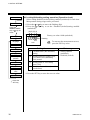
Locking/Unlocking setting operation (Operation Lock)
Select setting disabled (locked)/setting enabled (unlocked) for each item.
Misoperation during usage can be prevented.
1. Press the or key to move the flashing digit.
2. Press the or key to set the “Disabled (locked)/setting enabled
(unlocked).”
(4) (3) (2) (1)
Factory set value: 0000 (unlocked)
Setup (Fn9)
Flashing
Display
language
To return to the measurement screen,
press the ESC key twice.
Lock
Date format
Sensor type
Display unit
Decimal point
position
PV Bias
Digital filter
Auto power
OFF
Setting items
(1) Calendar timer (date and time)
setting
(2) Setting items of Logging (Fn3),
User Name (Fn8) and Setup
(Fn9) menus.
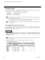
Data range
0: Setting enabled
(unlocked).
1: Disabled (locked)
(3) Setting items of TAG Setup
menu (Fn2)
(4) Deletion of record data (1 or all
records data)
3. Press the SET key to store the new set value.
Operation lock
: Press the
SET key
36
IMR01X01-E3
9. MANAGING DATA BY PC
[ONLY FOR DP-700B]
For the DP-700B, it is possible to manage recorded (logging) temperature data, tag and initial
set data stored in the memory by a personal computer with the DP-700B connected to the
USB port of the computer.
This chapter describes procedures for connecting the DP-700B to a personal computer and
also for managing stored data.
<System Requirements for a USB Connection>
Personal Computer:
OS:
DOS/V PC and PC98-NX Series loaded with USB port (USB 2.0/1.1)
Windows XP (32-bit and 64-bit versions),
Windows Vista (32-bit and 64-bit versions),
Windows 7 (32-bit and 64-bit versions)
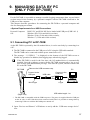
9.1 Connecting PC to DP-700B
As the DP-700B is operated by the OS standard driver, it can be used only by connecting it to
a PC.
1. The DP-700B is connected to the USB port of a PC using the USB cable attached.
The DP-700B can be connected with the power turned on or off. *
2. The message “ ***USB*** ” is displayed on the bottom of the DP-700B screen to
disable key operation. In addition, data logging stops when being logged.
If the DP-700B is used for the first time, the OS standard driver is automatically
installed. Start the windows system with the DP-700B unconnected to log on as a
user account with administrator privilege. First start the system, and then connect the
PC to the DP-700B.
DP-700B
Remove the USB connector cap.
Connect to the
USB port
Mini B type
(Right view)
USB cable
PC
Connect to the
USB port
A type
USB cable length: 1 m
* The DP-700B is compatible with the USB bus power. The power is supplied from the USB port
on the PC side via the USB cable when connected with USB. It is possible to manage data by
connecting USB even with the DP-700B power turned off.
3. Open “Devices and Printers” of Windows to newly add the “USB mass storage device”
icon.
IMR01X01-E3
37
9. MANAGING DATA BY PC [ONLY FOR DP-700B]
9.2 Storing Data
Open “Devices and Printers” of Windows to double click the “USB mass storage device” icon.
Thus, three CSV files in the DP-700B memory area displayed.
LOG_.CSV:
Recorded (logging) temperature data
TAG_.CSV:
Tag setting data
SETUP_.CSV: Initial setting data
The LOG_.CSV, TAG_.CSV and SETUP_.CSV files are created when the
DP-700B is connected to USB.
As a file name of each file created, characters of identifying each entity (DP-700B)
are entered in . Thus, two or more DP-700B files are identified.
If no temperature data is stored within the DP-700B memory, the LOG_.CSV file
is not displayed.
LOG_.CSV (Recorded temperature data)
Recorded (logging) temperature data. Read only file. It can be opened and referred to by table
calculation software such as Excel. In addition, it can be copied it stored at a location other
than the DP-700B using a new name.
CAUTION
Deleting the LOG_.CSV file also clears all recorded temperature data
within the DP-700B memory. Take care not to delete necessary recorded
temperature data.
If no temperature data is stored within the DP-700B memory, the LOG_.CSV file
is not displayed.
Contents of file: Memory No., Date, Time, Temperature, Tag No., User No.
< When opened by Excel >
38
IMR01X01-E3
9. MANAGING DATA BY PC [ONLY FOR DP-700B]
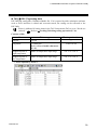
TAG_.CSV (Tag setting data)
DP-700B tag setting data. Writable/readable file. If it is opened by table calculation software
such as Excel and then is edited and overwrite-stored, the setting can be reflected to the
DP-700B.
Writes is inhibited if setting items in the TAG Setup menu (Fn2) is set to “Not be set
(locked).”
Refer to Locking/Unlocking setting operation (P. 36).
Contents of file:
Name
Data range
Factory set value
Tag No.
1 to 99
Tag Name
11 characters
Refer to List of usable characters
(P. 41)
Judgment point of
high temperature
Same as temperature input range
0.0 C or 32.0 F
Judgment point of
low temperature
Same as temperature input range
0.0 C or 32.0 F
TAG01 to 99
< When opened by Excel >
IMR01X01-E3
39
9. MANAGING DATA BY PC [ONLY FOR DP-700B]
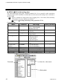
SETUP_.CSV (Initial setting data)
DP-700B initializing setting data. Writable/readable file. If it is opened by table calculation
software such as Excel and then is edited and overwrite-stored, the setting can be reflected to
the DP-700B.
Writes is inhibited if setting items in the Logging (Fn3), User Name (Fn8) and Setup
(Fn9) menus are set to “Not be set (locked).”
Refer to Locking/Unlocking setting operation (P. 36).
Contents of file:
Name
Command
User name
User=
Display language
Language=
Date format
Date_format=
Sensor type
Input=
Display unit
Unit=
Decimal point
position
PV bias
Digital filter
Auto power OFF
Interval time
TempDP=
TBias=
TFilter=
AutoOFF=
Interval=
Data range
Factory set value
11 characters
Refer to List of usable
characters (P. 41)
0: Japanese
1: English
0: Month/Day
1: Day/Month
0: Thermocouple K
1: Thermocouple J
2: RTD (Pt100)
3: Thermocouple T
0: C
1: F
0: No decimal place
1: One decimal place
99.9 to 99.9 C (F)
0 to 100 seconds (0: OFF)
0 to 60 minutes (0: OFF)
0 to 3600 seconds (0: OFF)
Blank (No name)
1
0
0
0
1
0.0
0
3
0
< When opened by Excel >
Command
User No., User name
Setting data
40
IMR01X01-E3
9. MANAGING DATA BY PC [ONLY FOR DP-700B]
List of usable characters
Numeral
Alphabets
Symbols
0123456789
ABCDEFGHI
JKLMNOPQR
STUVWXYZ
abcdefghi
jklmnopqr
stuvwxyz
@!#$%&’`
+-.;=^_
()[]{}
Spaces cannot be used.
Storing data in hard disk of PC
Copy data to the hard disk of the PC using Windows Explorer.
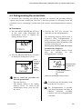
9.3 Disconnecting DP-700B from PC
Disconnect the DP-700B from the PC after the PC power is turned off or according to the
following steps.
Do not disconnect the DP-700B from the PC when the file is opened or while the
file is being stored. Malfunction may result.
The DP-700B can be disconnected with the power turned on or off.
The disconnecting procedure is described in “Windows 7.” Icons and windows
displayed differ depending on OS used. For details, refer to the manual for
“Windows.”
1. Check that the file is not opened or it is being stored. Close when the file is opened.
2. Click “Show hidden icons”
in the taskbar. The notification area is displayed.
3. Click “Safely Remove Hardware”
in the notification area.
4. Click “Eject USB mass storage devices” in the displayed menu.
The displayed contents depend on the number of USB devices
connected to your computer. Carefully click the icon not to select a
wrong device.
5. The “Safely Remove Hardware” icon
moves to the notification area. When you see
the message “Safe to remove hardware - The USB mass storage device can now be safely
removed from the computer,” remove the device from your computer.
6. Disconnect the DP-700B from the PC.
IMR01X01-E3
41
10. APPENDIX
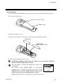
10.1 Replace the Battery
If
(Battery service life is going to expire) is displayed, immediately replace the battery.
Replace battery: Type LR6 (based on IEC and JIS) alkaline battery, One battery
Battery life:
Can be operated for 400 hours continuously (Around the ambient
temperature 23 C). However, the battery service life varies depending
on the operating condition and environment. Therefore, the above service
life period is only for reference.
If the battery is replaced, the instrument is reset-started. Therefore, there are
some data items to be initialized. In addition, for the DP-700A all recorded data
items are deleted. The state of each data when the battery is replaced (when
reset-started) is shown in the following.
Monitor items
Name
Peek hold
Bottom hold
Recorded (logging) data
DP-700A
DP-700B
Reset
(Peak hold value becomes measured temperature just when reset.)
Reset
(Bottom hold value becomes measured temperature just when reset.)
All recorded data clear
Hold
Setting items
Name
Tag Filter
Tag Name
Judgment point of high
temperature
Judgment point of low
temperature
Interval time
User No. selection
User name
Display language
Date format
Sensor type
Display unit
Decimal point position
PV bias
Digital filter
Auto power OFF
Operation lock
Year
Date
Time
42
DP-700A
DP-700B
Initialize (OFF)
Hold
Hold
Hold
Hold
Initialize (User No. 1)
Hold
Hold
Hold
Hold
Hold
Hold
Hold
Hold
Hold
Calendar timer setting: Can be set (Unlock)
Other setting items: Hold
Initialize (0)
Initialize (01/01)
Initialize (00:00)
IMR01X01-E3
10. APPENDIX
Procedures
1. Press the MENU/POWER key for more than two seconds to turn off the DP-700 power.
2. Loosen the battery cover.
Turn the cover with a coin.
Battery cover
3. Remove the battery cover.
4. Remove the old battery. Load a new battery without mistaking its polarity.
Old battery
New battery
Alkaline battery (LR6)
5. Then, firmly tighten the battery cover.
Insufficient tightening cannot assure the effect of water resistance (DP-700A:
Equal to IP67, DP-700B: Equal to IP54).
After the battery is loaded, the instrument is ready to be
reset-started.
The function menu “Utility (Fn0)” for setting the
dominical year is displayed on the LCD screen. If no
dominical year is set, no calendar function can be used.
Always set the year if the calendar function is used.
Year
Year setting screen
Pressing the ESC key twice can display the measurement screen.
IMR01X01-E3
43
10. APPENDIX
10.2 Cleaning
Turn off the power supply before cleaning the instrument.
Moisten a soft cloth with a diluted neutral detergent, completely wring the cloth, then wipe
the instrument with cloth. Do not use a volatile solvent such as paint thinner to clean the
instrument. Deformation or discoloration will occur.
The DP-700A can be washed in flowing water as it has water and dust resistant characteristics
equal to IP67.
However, the DP-700B (Water/dust resistance equal to IP54) cannot be washed in flowing
water.
10.3 Troubleshooting
This section describes probable causes and treatment procedures if any abnormality occurs in
the instrument. For any inquiries, please contact RKC sales office or the agent, to confirm the
specifications of the product.
Prior to replacing the sensor, always turn off the power.
10.3.1 Error displays
Displays and description of errors are described in the following table:
Display
Description
Service life is going to expire.
Service life has expired.
Solution
Replace the new battery.
Refer to 10.1 Replace the
Battery (P. 42).
Burnout
The sensor is broken, shorted or
imperfectly connected.
Check sensor and sensor
connection.
C
Check input type, input
range, sensor and sensor
connection.
[Flashing]
Overscale
Measured temperature is above
the 5 % of measuring range high
limit value or display range limit
high (9999).
C
[Flashing]
Underscale
Measured temperature is below
the 5 % of measuring range low
limit value or display range limit
low (1999).
Continued on the next page.
44
IMR01X01-E3
10. APPENDIX
Continued from the previous page.
Display
Description
C
Adjusted data error
Adjusted data range is abnormal.
(Err 1)
C
EEPROM error
Response signal from EEPROM is
abnormal.
Data write failure
C
A/D conversion error
Response signal from A/D
converter is abnormal.
A/D conversion count value is out
of the specified range.
Solution
First remove the battery, and
then load it again after a
lapse of a few seconds.
If not normally operated with
the battery re-loaded, please
contact RKC sales office or
the agent.
(Err 2)
(Err 4)
C
Stack overflow
Stack point overflows
(Err 64)
C
Watchdog timer error
The part of an internal task stops
the action.
(Err 128)
If two or more self-diagnostic errors occur (Err 1, Err 2, Err 4, Err 64 and Err 128),
the value obtained by adding the error number to the Err display is displayed.
IMR01X01-E3
45
10. APPENDIX
10.3.2 Problem and solution
Problem, possible cause and solution of trouble described in the following table:
Problem
No power is turned on.
(No display appears)
Measured temperature
display is abnormal
Possible cause
Solution
No battery is loaded.
Load a battery.
Refer to 2.1 Loading Battery
(P. 5).
The battery with less
service life is used.
Replace the new battery.
Refer to 10.1 Replace the Battery
(P. 42).
The battery with less
service life is used.
Replace the new battery.
Refer to 10.1 Replace the Battery
(P. 42).
Noise source is present
near the instrument
Separate the noise source from the
instrument.
Set the digital filter.
Refer to To lessen the fluctuation
of a display value caused by noise
(P. 35).
Measured temperature
display value differs from
the actual value
Proper sensor is not
used
Use the specified sensor.
Sensor insertion depth
is insufficient
Check whether sensor is inserted
loosely. If yes, fully insert the
sensor.
Sensor insertion
position is not
appropriate
Insert the sensor at the specified
location.
PV bias is set
Set the PV bias to “OFF.”
Refer to To correct the
temperature display value (P. 34).
However, this is limited only to
when the PV bias setting can be
changed.
The display does not change CPU overrun
No key operation is accepted
46
First remove the battery, and then
load it again after a lapse of a few
seconds.
If not normally operated with the
battery re-loaded, please contact
RKC sales office or the agent.
IMR01X01-E3
10. APPENDIX
10.4 Specifications
Input
Input type:
Measuring range:
Universal input
Thermocouple:
RTD:
Thermocouple K:
Thermocouple J:
Thermocouple T:
RTD Pt100:
Sampling cycle:
PV bias:
Digital filter:
K, J, T (JIS-C1602-1995)
Pt100 (JIS-C1604-1997)
200 to 1372 C (Resolution: 1 C)
328 to 2501 F (Resolution: 1 F)
199.9 to 999.9 C (Resolution: 0.1 C)
199.9 to 999.9 F (Resolution: 0.1 F)
200 to 1200 C (Resolution: 1 C)
328 to 2192 F (Resolution: 1 F)
199.9 to 999.9 C (Resolution: 0.1 C)
199.9 to 999.9 F (Resolution: 0.1 F)
50 to 400 C (58 to 752 F)
50.0 to 400.0 C (58.0 to 752.0 F)
200 to 850 C (Resolution: 1 C)
328 to 1562 F (Resolution: 1 F)
199.9 to 850.0 C (Resolution: 0.1 C)
199.9 to 999.9 F (Resolution: 0.1 F)
0.5 seconds
99.9 to 99.9 C (F)
First order lag digital filter:
Time constant: 0 to 100 seconds (0: OFF)
Moving average: 4 times (fixed)
Performance
Display accuracy (At the ambient temperature 23 C ± 2 C):
(0.1 % of display value 1 digit) or 0.3 C (0.6 F)
Less than the value whichever is greater
Cold-junction temperature compensation error:
0.5 C (Within 5 to 40 C)
1.0 C (Within 20 to 5 C and 40 to 50 C)
Ambient temperature influence:
0.01% /C of span (Within 5 to 40 C)
0.02% /C of span (Within 20 to 5 C and 40 to 50 C)
Display
Reflective FSTN LCD
Measured temperature:
Display memory No.:
Total number of recorded data:
Message:
Recorded (logging) execution:
Burnout:
Remaining battery service life:
Temperature unit:
IMR01X01-E3
4-digit
4-digit
4-digit
68 8 dots (11 characters)
Lit during execution, flashing during stop for automatic recording.
Lit when the sensor is disconnected, shorted or imperfectly contacted.
The remaining battery service life is indicated in three steps.
12 8 dots (C/F)
47
10. APPENDIX
Data recording (logging)
Recording method:
Interval time:
Recording items:
Recording capacity:
Memory backup:
Manual logging mode:
Can be manually recorded in the memory.
Automatic logging mode: Can be automatically recorded (in a set
interval) in the memory.
0 (Manual log mode), 1 to 3600 seconds
Measured temperature, Tag name, Date, Time
DP-700A: Maximum 99 logs
DP-700B: Maximum 9999 logs
DP-700A: Backed up by SRAM
The recorded data may be lost if the battery service
life has expired or the battery is replaced.
DP-700B: Backed up by non-volatile memory (EEPROM)
Number of writing:
Approx. 100,000 times
Data retaining period: Approx. 10 years
Depending on storage and operating conditions
Simplified Judging Function
The judgment points of high and low temperatures are set. When within the judgment points,
“” is displayed while when out of the judgment point, “” is displayed.
is displayed, if out of the high judgment point, while
, if out of the low judgment point.
Tag number function
Number of maximum registration:
DP-700A: 5 tags
DP-700B: 99 tags
Registration items:
Tag name, judgment points of high and low temperatures
Tag name:
11 characters (Numeral, Alphabets, Symbols)
Memory backup:
Backed up by non-volatile memory (EEPROM)
Number of writing:
Approx. 100,000 times
Data retaining period: Approx. 10 years
User name function (Only for DP-700B)
Number of maximum registration:
99 names
Number of character:
11 characters (Numerals, Alphabets, Symbols)
Memory backup:
Same as Memory backup of Data recording (logging)
USB function (Only for DP-700B)
Interface:
Based on USB (Universal Serial Bus) Ver2.0
Communication speed (Theory value):
Full Speed compliant (12 Mbps)
Connector type:
USB series Mini-B
Connection:
The DP-700B is connected to the USB port of a PC using the USB
cable attached.
Power supply:
Bus power (The power is supplied from the USB port on the PC side.)
Device class:
Mass Storage Class (Bulk-Only Transport)
Compatible OS:
Windows XP (32-bit and 64-bit versions),
Windows Vista (32-bit and 64-bit versions),
Windows 7 (32-bit and 64-bit versions)
48
IMR01X01-E3
10. APPENDIX
Other functions
Peak and bottom hold, Calendar timer, Operation lock, Self-diagnostic
Power
Battery:
Battery life:
Power consumption:
Type LR6 (based on IEC and JIS) alkaline battery, One battery
Approx. 400 hours (Continuous operating time, Around the ambient
temperature 23 C).
However, the battery service life varies depending on the operating
condition and environment. Therefore, the above service life period is
only for reference.
10 mW (Mean value while operated)
Standards
Waterproof and dustproof:
CE marking:
C-Tick:
DP-700A: IP67
DP-700B: IP54
EMC:
EN61326-1, Annex A
EN55011
General specifications
Memory backup:
Backed up by non-volatile memory (EEPROM)
Number of writing:
Approx. 100,000 times
Data retaining period: Approx. 10 years
Depending on storage and operating conditions
Backup data:
Interval time, Display language,
Sensor type, Display unit,
Decimal point position,
PV bias, Digital filter,
Auto power OFF, Operation lock,
Date format
Allowable ambient temperature:
20 to 50 C
However, in an environment of less than 0 C, the LCD response
speed remarkably decreases.
Allowable ambient humidity: 5 to 95 %RH
Absolute humidity: MAX.W.C 29.3 g/m3 dry air at 101.3 kPa
Dimensions:
57 (W) 152 (H) 46 (D) mm
Weight:
Approx. 150 g (Including battery)
IMR01X01-E3
49
MEMO
50
IMR01X01-E3
The first edition: DEC. 2003 [IMQ00]
The third edition: NOV. 2012 [IMQ00]
RKC INSTRUMENT INC.
HEADQUARTERS: 16-6, KUGAHARA 5-CHOME, OHTA-KU TOKYO 146-8515 JAPAN
PHONE: 03-3751-9799 (+81 3 3751 9799)
FAX:
03-3751-8585 (+81 3 3751 8585)
E-mail: [email protected]
Website: http://www.rkcinst.com/
IMR01X01-E3
NOV. 2012