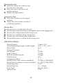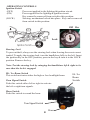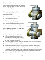
1
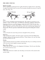
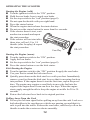
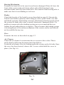
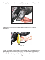
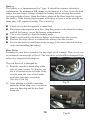
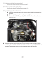
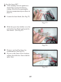
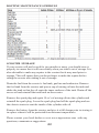
Venice LX 49cc Owner’ Owner’ss Manual Table of Contents Safety Notes .......................................................................... Page 2 Description ............................................................................ Page 3 Specifications ........................................................................ Page 4 Instruments & Indicators ....................................................... Page 5 Operating Controls ................................................................ Page 6 Pre-Ride Checks ....................................................................Page 11 Operating the Scooter ........................................................... Page 12 Routine Maintenance ............................................................ Page 13 Trouble Shooting .................................................................... Page 19 Ignition Module Replacement ................................................ Page 22 Routine Maintenance Schedule ............................................. Page 23 Scooter Storage ..................................................................... Page 23 Warranty Statement...........................................................Appendix To download a PDF version of this scooter manual with color illustrations, visit us at:www.tngscooters.com Thank you from all of us at CMSI Inc. for purchasing your TN’G Venice scooter. We trust that you will have many happy & trouble-free travels on your scooter for many years to come. SAFETY NOTES Always obey traffic signs. Always ride at a safe speed. Always wear a helmet that fits correctly. Never wear loose clothing which could catch on the controls or wheels. Do not carry a passenger. Do not overload the scooter. Do not carry more than 3 pounds on the carrying hook. Do not carry more than 20 pounds in the luggage box. Be sure there is no source of heat or flame near the scooter during servicing. Never operate the scooter in an enclosed area. After the scooter has started, do not touch the hot muffler system. Carry objects at the designated areas only. Never modify the scooter in any way. 2 DESCRIPTION Rear View Mirror Throttle Seat Headlight Muffler 2 Cycle Mixing Oil Cover Speedometer Rear Brake Lever Ignition Switch VIN Number Kick Starter 3 Fuel Filler Cap (under seat) Opening the Seat Insert the ignition key into the seat lock & turn to the right. Raise the rear of the seat to the upright position. Remove the ignition key. Closing the Seat Press the seat down to its normal position. Check the seat to make sure that it is locked in position. Storage Box The storage box is located under the seat. Do not place items that may be damaged by heat in the luggage box. Do not place fragile items in the storage box. Do not store valuables in the storage box. Do not carry oil or fuel in the storage box. Do not allow water to collect in the storage box. SPECIFICATIONS Model Number Outer Dimensions (length, width, height) Wheel Base Ground Clearance Dry Weight Load Capacity Most Economical Speed Displacement Compression Ratio Rated Power (with restrictor installed) Rated Power (without restrictor installed) Spark Plug Type Spark Plug Gap Start Types Ignition Type 4 Venice LX-2 66.9” x 25” x 41.3” 46.5” 3” 165 lbs 330 lbs 20 mph 49cc 7: 1 2.0 HP @ 7000 RPM 4.3 HP @ 7000 RPM E7TC 0.7 - 0.9mm Electric, Kick CDI Transmission Fuel Capacity Rear Drive Oil Type Rear Drive Oil Capacity Fuel Mixing Oil Fuel Mixing Oil Capacity Clutch Front Tire Pressure Rear Tire Pressure CVT 5.5 Liters / 1.5 Gals SAE20W-40 Gear Box (100 cc) Amsoil (Synthetic 2-stroke) 40 fluid oz Dry, automatic centrifugal 25 PSI 30 PSI INSTRUMENTS & INDICATORS Speedometer- Indicates the speed of the scooter. Odometer- Indicates the accumulated mileage in Kilometers. Turn Signal Indicator- Illuminates when turn signals are activated. High Beam Indicator- Illuminates when headlight high beam is on. Fuel Gauge - Shows fuel level. Low Mixing Oil Indicator- Illuminates when mixing oil level is low. Odometer Speedometer Low Mixing Oil High Beam Turn Signal Fuel Gauge 5 OPERATING CONTROLS Ignition Switch (OFF) Power not applied to the lighting & ignition circuit. (ON) Power applied to the lighting & ignition circuit. Key cannot be removed from switch in this position. (LOCK) Steering mechanism locked into place. Key can be removed from switch in this position. Off On Lock Steering Lock To prevent theft, always use the steering lock when leaving the scooter unattended. To apply the steering lock, turn the handlebars fully to the left. Insert the ignition key in the OFF position, press in the key & turn it to the LOCK position. Remove the key. Note: Test the steering lock by swinging the handlebars left & right to be sure that the lock is engaged. Hi / Lo Beam Switch This switch activates either the high or low headlight beam. Turn Signal Switch Push this switch either left or right to activate the left or right turn signals. Horn Switch Push this switch to sound the horn. Turn Signal Switch Horn 6 Hi / Lo Beam Switch Stop Switch The Stop switch has two positions: Stop- Engine stops running. Run- Engine can run. Stop Position Start Button Turn the key in the ignition switch to on, hold the rear brake lever lightly, press the starter button & the starter motor will crank the engine. Release the starter button as soon as the engine starts. Run Position Starter Button Rear View Mirror Installation Screw the installation nut onto the mirror stem & then screw the mirror stem into the mounting hole of the handlebar. After the mirror stem is firmly mounted to the handle bar, tighten the installation nut with a wrench to prevent the mirror from turning. Loosen the installation nut when adjusting the mirror position & retighten afterwards. Fig. 1 Mirror Adjustment The side mirrors have two methods of adjustment. They can be adjusted either left & right or up & down. Use a wrench to loosen the adjustment nut. (See Fig 1) While sitting on the scooter, look into the side mirror and adjust the mirror stem until you see a clear view of what’s behind the scooter. Now retighten the adjustment nut. To adjust the mirrors up & down, locate the screws which tighten the hand controls on the handlebars. (See Fig. 2) 7 Fig. 2 Adding 2-cycle Mixing Oil Whenever the red “Low Mixing Oil” warning lamp turns on, you should add mixing oil as soon as possible. Open the mixing oil cover on the right side of the scooter and refill the mixing oil tank with a high quality 2-stroke oil such as Opti-2. This will protect the engine’s moving parts and ensure that you will receive the most power from the engine as well as the longest engine life. Opti-2 can be found at your local Twist N’ Go Dealer. WARNING! Do NOT add any oil to engine transmission when red oil light turns on. Adding Fuel Note: Turn the engine off when refuelling Remove all source of flame from the area when refuelling. Unlock and lift seat, remove cap and add fuel. Capacity is approximately 1.5 gallons. DO NOT pre-mix oil with fuel. Oil will be added automatically during operation provided the oil reservoir has 2-cycle oil in it. After fuel is filled, replace cap making sure it is tight and threaded correctly Fuel Cap (Under Seat) 8 Adjusting the Brakes Rear Brake Adjustment Park the scooter on its center stand on a flat surface. Check the rear brake free play by measuring how far the tip of the brake lever will move until it begins to resist further movement. (See Figs 11 & 12) Brake lever at rest. (See Fig. 11) Fig. 11 Brake lever travels between 10 & 20 mms from rest until resistance is felt. (See Fig 12) Here the lever has been squeezed to the point of resistance which is approximately 15 millimeters from where it was at rest. Fig. 12 Use a 14 mm wrench to adjust the brake adjustment nut on the wheel until the brake lever free play is between 10 to 20 mm. (See Fig 13) Fig. 13 9 When turning the brake adjustment nut, make sure that the nut rests in the correct position when you remove the wrench. The concave surface of the nut must rest flush against the pivot pin. (See Fig 14) CORRECT Make sure that the brake adjustment nut does not look like Fig 15! This brake has been adjusted incorrectly. The scooter is not safe to ride if the adjustment nut is not positioned correctly! Check the rear wheel for drag without the rear brake being applied. If there is any drag, loosen the adjustment nut. If there is too much free play in the rear brake lever, then the adjustment nut will need tightening. Fig. 14 INCORRECT Concave Note: Adjust the nut only 1/2 turn and then recheck the brake operation. Starting the Engine for the First Time Turn the ignition switch to the “ON” position, apply the rear brake with the Fig. 15 left hand lever and set the stop switch to the “run” position (see page 8). Look to see that the scooter lights are operating. This will verify that you have installed the battery correctly. Use your foot to extend the kick start lever. Quickly press down on the kick start lever with your foot. Immediately remove your foot from the kick start lever so that it can spring back into position. If the engine doesn’t start the first time, repeat the procedure. The engine may require many kicks to move the fuel into the engine for the very first time. When the engine starts, apply enough throttle to keep the engine at an idle for 20 to 30 seconds. Retract the kick start lever back to its original position. 10 PRE-RIDE CHECKS Brake Freeplay When applying a gentle pressure on the front & rear brake levers, check the freeplay measured at the lever tip. The freeplay should be between 10 and 20 mm. (See Page 10) Tires Tire pressure should be checked frequently. The cold tire pressures are as follows: Front 25 PSI Rear 30 PSI Tires should be regularly checked for damage to the rim as well as damage to the tire itself. Look for any cuts, embedded nails, or other sharp objects. Check for excessive wear as well. If there is damage to the rim, the rim may have to be repaired and rebalanced afterwards. The tire pressure should be checked prior to riding the scooter. (cold) Fuel Always check to be sure that you have enough fuel for your trip. Electrics After starting the engine, check for proper operation of the headlight and taillight. Operate the turn signals and horn. Check them to be sure that they are functioning correctly. Brakes Apply both the front & rear brakes and check that they are working correctly. Also check the brake light for proper operation. Rear-View Mirrors Check the rearview mirrors for alignment & damage. Also be sure that they are clean for the best view. Reflectors Check the reflectors to make sure that they are clean & well secured to the scooter body. 11 OPERATING THE SCOOTER Starting the Engine (cold) Turn the ignition switch to the “ON” position. Hold the rear brake lever to apply rear brake. Set the stop switch to the “run” position (page 8). Do not open the throttle with your right hand. Press the starter button. When the engine starts release the starter button. Do not press the starter button for more than five seconds. If the scooter doesn’t start, wait another ten seconds and repeat the start procedure. If the scooter will not start after three tries, roll on 1/8 to 1/4 throttle (after freeplay) & repeat the start procedure. Starting the Engine (warm) Turn the ignition switch to the “ON” position. Apply the rear brake. Set the stop switch to the “run” position (page 8). Press the starter button or use the kick starter. Kick-Starting the Engine Turn the ignition switch to the “ON” position & apply the rear brake. Use your foot to extend the kick start lever. Quickly press down on the kick start lever with your foot. Immediately remove your foot from the kick start lever so that it can spring back up into position. If the engine doesn’t start the first time, repeat the procedure. The engine may require several kicks to move the fuel into the engine if the engine hasn’t been run for a few days. When the engine starts, apply enough throttle to keep the engine at an idle for 20 to 30 seconds. Retract the kick start lever back to its original position. Pulling Away From the Curb Put on your left turn signal before pulling away from the curb. Look over both shoulders to be sure than no vehicles are passing you and that it is safe to pull into the traffic. Release the rear brake, and slowly roll on the throttle to make the scooter accelerate smoothly. 12 Controlling the Speed The scooter’s speed is adjusted by the throttle control. Rotate the control counterclockwise slowly to increase the speed, and rotate the control clockwise to decrease the scooter’s speed. Using the Brakes The brakes work best when the front and rear brakes are applied at the same time. To apply the brakes: Roll off the throttle quickly, and squeeze the front brake lever while putting pressure on the rear brake lever with your left hand. Do not apply the brakes too quickly or apply the brakes while in a turn, as loss of traction and control may result. Wet conditions will affect brake effectiveness. It is advisable to give yourself twice the normal braking distance in wet or slippery conditions. Take extra care while riding in these conditions. Test your brakes after washing your scooter or riding through a large pool of water. If this happens, apply the brakes gently until they dry themselves and work effectively again. Stopping the Scooter Roll off the throttle and steer the scooter to the side of the road. Gently apply the front brake with your right hand, and at the same time apply the rear brake with your left hand. Extend your left foot just before coming to a complete stop so as to keep the scooter upright when it stops. Turn off the ignition key and dismount the scooter on the left side. Exit the scooter on the left side and use your right foot to extend the side stand of the scooter. If the scooter is to be parked for an extended period of time, use the center stand instead. ROUTINE MAINTENANCE The scooter should be inspected at monthly intervals using the following list of items to check. Use a flat area and support the scooter in an upright position. Use caution if the engine and exhaust assembly are hot! Never start the engine in an enclosed area. If you find a problem correct it immediately. To do otherwise is unsafe. 13 Steering Mechanism Examine the front fork to be sure it is not bent or damaged. Raise & lower the front of the scooter and rock it from side to side while listening for any unusual sounds caused by bent front forks. Also turn the front steering axle to make sure that it is not binding or too loose. Brakes Check the freeplay of the brake levers as described on page 10. Operate the front & rear brakes separately while riding at a slow speed. Make sure that each brake system is functioning correctly. If the brakes function poorly check the scooter for brake shoe wear, or poorly lubricated / damaged cables. If a problem is suspected with a braking system part we recommend that you replace the part rather than try to repair it. This is because the braking system is an integral part of the safety mechanism of the scooter, and as such should not be modified in any way. Tires Examine the tires as described on page 12. Air Cleaner Check the air cleaner for restrictions due to excessive dirt or dust. This is easily done by following the instructions listed below. Locate the air cleaner cover by looking under the scooter on the left side. Once the cover has been located, remove the 3 screws which hold the cover in place. (See Fig. 16) 1 2 3 Fig. 16 14 Once the 5 screws have been removed, the cover can be carefully opened to reveal the filter element located within. (See Fig 17) Fig. 17 Gently remove the filter element for inspection & possible cleaning. (See Fig 18) Fig. 18 The air filter can be cleaned using compressed air and returned to service. If inspection of the filter shows any tears, or the filter cannot be adequately cleaned with compressed air, then the filter must be replaced. Use caution to reseat the filter correctly after cleaning or inspection. 15 Battery The battery is a “maintenance free” type. It should not require electrolyte replacement. To maintain a full charge on the battery, it is best to use the kick starter for short trips. Always charge the battery before storing the scooter for long periods of time. Open the battery plate on the floor board to expose the battery. If the battery posts appear to be dirty or have a white powder on them, they will require cleaning. This is done by: Check to see that the ignition is turned off. Disconnect the negative wire first, then the positive wire from the battery and lift the battery out of the battery compartment. Use a wire brush to clean the battery posts. Gently wash and dry the battery before replacing it into the scooter. Reverse the steps above to reinstall the battery into the scooter. Review the battery installation steps on page 8 for more detailed instructions on reinstalling the battery. Rear Drive Examine the rear drive assembly for any signs of oil leakage. There is no way to accurately measure the oil level. The rear drive oil should be changed if the oil level is suspected of being low. The rear drive oil is changed by: 1) Find the rear drive drain plug at the rear of your scooter. It’s hard to see, but it’s located on the left side of the scooter near the rear wheel underneath the rear drive assembly. (See Fig 19 & 20) 2) After placing a suitable container under the drain plug, use a wrench to unscrew the plug and let the fluid drain out. Fig 19 16 Fig 20 3) After the fluid has stopped draining, replace the drain plug in the drain hole and tighten the plug with a wrench until it is snug. (Do not overtighten the plug!) 4) Unscrew the rear drive oil filler cap located on top of the rear drive assembly beside the rear wheel. (See Fig. 21) Fig. 21 5) Use a small funnel to pour in 100 cc’s of SAE20W-50 oil into the rear drive. (See Fig 22) 6) Replace the rear drive oil filler cap and tighten the cap until snug. Fig. 22 Lights Open the headlight & taillight assemblies to look for damage & clean out any accumulated dust. Operate the turn signals & check them for correct operation. Check the turn signals for physical damage. 17 Spark Plug Locate the spark plug by parking the scooter on it’s side stand and looking at the cylinder head from the left side of the scooter. (See Fig 23) Fig. 23 Pull off the spark plug cap, and remove the spark plug with the spark plug wrench provided in the tool kit. Insert the spark plug back into the spark plug cap. While touching the threads of the spark to the exhaust manifold bolt, turn on the ignition and crank the engine over with the kick starter. (See Fig 24) Note: only turn the ignition key when the plug is grounded. In this case, touching the exhaust manifold bolt. Failure to do so may result in electrical damage. Fig. 24 If the spark appears weak, replace the spark plug. Check that the gap is 0.035 +/- .002 inches. Reinstall the spark plug. 18 Carburetor Adjustment Start the engine and let it idle for 5 minutes. Adjust the idle adjustment screw until the engine idles at 1500 +/- 100 RPM. (See Fig 25) Idle Adjustment Screw Fig. 25 Better access to the carburetor is obtained by raising the seat and removing the screws which hold the luggage box in place. Then remove the luggage box and seat assemblies. Check for signs of fuel leaks at the fuel tank, hose, and carburetor. Reinstall the luggage box and seat. MY SCOOTER WILL NOT START! This section is a handy reference to the most common reasons why your scooter will not start. Check each of the following suggestions until you discover what’s preventing your scooter from getting back on the road. 1) Is there fuel in the gas tank? Review the Adding Fuel section on page 11. 2) Did you squeeze the left brake lever? A safety switch requires that the left brake lever is squeezed before your scooter will start. 19 3) Is the stop switch in the run position? Review the Start Switch section on page 8. 4) Is there a spark at the spark plug? Review the Spark Plug section on page 21. 5) Is gas flowing to the carburetor? Raise the seat and remove the screws which hold the luggage box in place. Remove the luggage box and seat assemblies. Loosen the hose clamp and pull the fuel line from the carburetor. (See Fig 26) Carburetor Throttle Cable Fuel Line Starter Fig. 26 Hold the fuel line well below the level of the fuel in the fuel tank. While watching the end of the fuel line, kick the start lever repeatedly. If the fuel system is operational, fuel will flow from the end of the fuel line. 20 5) Are the fuses OK? After making sure the ignition is turned off, expose the battery wiring. (Review the opening the battery compartment procedure on page 8) Locate the fuse block (See Fig 27) Fig. 27 Slide the spare fuse holder over the end of the fuse block and open the fuse block. (See Fig 28) Fig. 28 Remove each of the fuses for examination. (See Fig 29) If you see the fuse wire is broken, replace the defective fuse with the spare fuse. Fig. 29 21 IGNITION MODULE REPLACEMENT If the ignition module must be changed, then use the following procedure. 1) Park the scooter on it’s side stand. Remove the center cover and side panel or seat box to expose CDI. Fig. 30 2) Remove the screw which holds the CDI unit in place. (See Fig. 30) 3) Lift the CDI unit out of the scooter. (See Fig. 31) Fig. 31 4) Disconnect the wires from the CDI unit and remove the unit completely from the scooter. (See Fig 32) 5) The CDI unit is not repairable. Exchange the faulty unit with a new one if required. A new unit can be installed by reversing the order of the steps 1 to 4. Fig. 32 22 ROUTINE MAINTENANCE SCHEDULE SCOOTER STORAGE If your scooter will not be used for two months or more, you should store it properly to ensure that it will run reliably when you take it out of storage. It is also advisable to make any repairs to the scooter that it may need prior to storage. This will ensure that you do not forget to make the repairs before riding the scooter after taking it out of storage. Drain the fuel from the scooter’s fuel tank, gas line and carburetor. Remove the fuel tank from the scooter and pour a cup of mixing oil into the tank and shake the tank so that the oil coats the inner surfaces of the tank. Drain off the excess oil and reinstall the tank back on the scooter. Remove the spark plug and squirt 10 cc’s of mixing oil into the cylinder and reinstall the spark plug. Leave the spark plug lead off the spark plug and use the electric starter to coat the inside of the cylinder with oil. Remove the battery from the scooter and give it a full charge prior to storing it in a place where it will be protected from extreme temperatures. Please contact your local dealer or us at www.tngscooters.com with any questions, comments or suggestions. 23 Warranty CMSI, Inc., warrants to the first retail purchaser of all TN’G vehicles, from an Authorized CMSI Dealer and each subsequent owner that the vehicle is free from defects in materials and workmanship for the period stated in this warranty section. To Qualify For This Warranty • The CMSI vehicles must be purchased from a dealer within the United States, Canada or Mexico who is authorized by CMSI to sell CMSI products. • Dealer must be signed up and be familiar with CMSI warranty policy. Warranty Verification Method Contact an authorized CMSI Dealer- Please be prepared to provide VIN# and Owner Name WARRANTY RESPONSIBILITY The Distributor CMSI Inc. To repair or replace , at its option, any part which is proven to be defective in material or factory workmanship under normal use for the applicable warranty period. • The repair or replacement of defective parts under this limited warranty must be made by an Authorized T N’G Dealer or service center. Warranty repairs will be made at no charge to you for parts or labor. • Parts repaired or replaced under warranty are warranted only during the balance of the applicable warranty period. The Authorized Dealer To give you complete warranty documentation when you pick up your vehicle. To perform warranty repairs on any T N’G product that qualifies for such repairs. The selling dealer shall sign the Acceptance Certificate and a Card of Delivery upon delivery of the vehicle.The Card of Delivery outlines the steps your dealer has taken to fulfill his responsibility to properly assemble and service your new T N’G and inform you of proper break-in, warranty and service. You, the Owner The customer is responsible to operate and maintain the motor vehicle according to this Owner’s Manual and service schedule. • The customer should retain all service records for future reference. • Service inspections and replacements in accordance with the time and mileage intervals given in the Maintenance Schedule are essential. • You are responsible for paying all maintenance costs, including service interval costs. • Failures which occur due to improper maintenance as determined by T N’G are not covered under this warranty. • The customer may choose the extended warranty option for engines on 50cc and above models by purchasing the Interlube Opti-4 engine lubricant at the time of purchase of the new unit and use only that lubricant during the entire warranty period. Your T N’G dealer is your best source for scheduled maintenance on your T N’G vehicle. Regardless of who performs your maintenance, if warranty repairs are needed, your T N’G dealer may ask you for documentation which may consist of one or more of the following: • A Maintenance Record showing the odometer mileage and service date. Each entry should be signed or stamped by a person who is qualified to service your motorcycle or yourself if you have performed the maintenance. • Copies of repair orders or other receipts for required maintenance that include the odometer mileage and service date. NOTE: All maintenance receipts should be kept by the owner. Warranty Time Period for 49cc scooter models CMSI provides one-year warranty coverage on parts and 3 months on labor. Coverage Begins The date the motorcycle is delivered to the first retail purchaser. Warranty CMSI shall repair or replace, at its option, any part (including parts of the emission control system) that is found defective in material or workmanship under normal use for the applicable time period. Parts or Labor No charge to you. WARRANTY DISCLAIMERS, LIMITATIONS & EXCLUSIONS Disclaimer of Consequential Damage & Limitation of Implied Warranties CMSI Inc. disclaims any responsibility for: • Loss of time • Loss of use of vehicle • Transportation expenses (rental and /or towing) • Any other incidental or consequential damage • Any other incidental or consequential expenses (storage) Duration of Implied Warranties Any Implied Warranties, including the implied warranty of merchantability and fitness for a particular purpose are limited to the duration of this written warranty. State Laws May Vary The previously listed limitations or exclusions may not apply to a motor scooter because of state laws. Some states may not allow limitations on how long an implied warranty lasts. Some states may not allow exclusion or limitation of incidental or consequential damages. Your Legal Rights These warranties give you specific legal rights. You may also have other rights which vary from state to state. It is the responsibility of the owner to be aware of state laws which pertain to this issue in your particular state. These Warranties Do Not Cover Failures which are not due to a defect in material or factory workmanship. Parts or accessories affected or damaged by: • Lack of required maintenance • Owner abuse or misuse • Accident and/or collision • Normal wear • Neglect • Improper installation • Unsuitable use in an application for which the part was not designed • The incorporation or use of unsuitable attachments or parts • The unauthorized alteration of any part • The incorporation or use of unsuitable attachments or parts • Deterioration from the elements • Failure to follow “break-in” procedures • Replacement of expendable maintenance item including, but not limited to: -Spark plug -gaskets -coolant-belts -Filters -hoses -lubricants -fuses -Tires (see Owner’s Manual) • Paint and/or decals fading, peeling, blistering, chipping or rusting. • Plastic body parts and panels Use for the following activities, shall VOID coverage: • Racing • Competition • Rental or other commercial uses • Towing another vehicle, trailor or similiar device • Alteration to the engine or drive train • Any operation or use outside of that described in this Owner’s Manual DISTRIBUTORS LIMITED WARRANTY – NEW MOTORCYCLE T N’G warrants to the first retail purchaser and subsequent purchasers of this vehicle that the motorcycle is free from defects in materials ands workmanship for the period stated in “Warranty Time Period”. To Qualify For This Warranty • • The vehicle must originally have been purchased from a dealer within the United States who is authorized by CMSI Inc to sell CMSI products. Prior to delivery to the purchaser, setup and pre-delivery service must be performed by a dealer or service center who is authorized by CMSI Inc to deliver it vehicles. Coverage begins • Original tire on motorcycle - date of delivery • Tire purchased as replacement - date of purchase Warranty Coverage Tires distributed and sold by CMSI which are either • Original equipment on CMSI vehicles, or • Specified by CMSI for the model the tire is installed on and purchased from an Authorized Dealer for replacement use. To qualify for this warranty • The tire must have been purchased from an Authorized CMSI Dealer. • The tire was part of the original factory equipment. • The tire must have been used for its designed purpose. DISTRIBUTOR’S LIMITED WARRANTY- MOTORCYCLE TIRES Warranty Time Period 90 days, or until the center tread is worn to a depth of 3/32" , whichever occurs first. • Alteration of the odometer so that the actual mileage connot be determined; alteration may VIOD coverage Replacement parts refer to Distributors Limited Warranties – Replacement Parts The Obligation of CMSI Inc To replace any tire which is proven to be defective in material or factory workmanship under normal use – until the tire center tread is worn to a depth of 3/32". At that point, there will be no further warranty consideration, regardless of the tire’s age or mileage. Your Obligation To practice proper tire care and prudent motorcycle operation. You must maintain tire inflation pressure and load in accordance with information in the manual, the tire information label on the motorcycle, and restrictions molded into the tire sidewalls. The replacement of a defective tire under this warranty must be made by an Authorized CMSI Inc Dealer. Replacement Charges – up to 50% tread wear Tire : No charge for a new direct replacement tire. Labor : No charge for mounting and balancing – to the tire’s original purchaser if the tire was factory or dealer installed. You pay for mounting and balancing - if the tire was sold un-installed. Replacement Charges – after 50% tread wear Tire : 50% charge for a new direct replacement tire. Labor : 50% charge for mounting and balancing. This Warranty Does Not Cover • Tires installed on non-CMSI Inc vehicles • Tires worn beyond the service limit specified in the appropriate Owners” Manual. • • • • • • • • Tires rendered unserviceable by road hazard damage, such as impact breaks, punctures, cuts, or snags. Tires rendered unserviceable by running while flat, spinning, improper inflation, overloading, misalignment, improper mounting during replacement of after repair, or installation on unsuitable rims. Tires rendered unserviceable due to abuse or misuse such as towing a trailer. Tube-type tires fitted without inner tubes. Tires which have been repaired. Tires whose sidewalls have been modified by the addition or removal of material. Tires with superficial weathering, checking, or cracking. Tires used in racing or other competition. DISTRIBUTOR’S LIMITED WARRANTY – REPLACEMENT PARTS Warranty Time Period 90 days coverage for genuine CMSI Inc parts for defects in material and workmanship: Coverage begins: The date of purchase from an Authorized CMSI Inc Dealer. To qualify for this warranty, the genuine TN’G part • Must have been purchased from an Authorized CMSI Dealer. • Must have been used in an application for which it was designed. Warranty Coverage • CMSI Inc will repair or replace, at its option, any genuine T N’G part that is defective in material or workmanship under normal use. • Proof of date of purchase is required. Parts installed by an Authorized CMSI/TN’G Dealer: Parts & Labor : No charge. Parts not installed by an Authorized CMSI/T N’G Dealer: Parts : No charge Labor : You pay for removal/installation charges This Replacement Parts Warranty Does Not Cover The following exclusions apply specifically to replacement parts in addition to the exclusions listed: • Tires (Refer to Distributor’s Limited Warranty – Motorcycle Tires) • The motorcycle in which the part is installed. • The color match of painted components (T N’G makes no warranty , expressed or implied, regarding the color match of painted components). REPORTING SAFETY DEFECTS If you believe that your vehicle has a defect which could cause an accident or could cause injury or death, you should immediately inform the National Highway Traffic Safety Administration (NHTSA) in addition to notifying CMSI Inc. If NHTSA receives similar complaints, it may open an investigation, and if it finds that a safety defect exists in a group of vehicles, it may order a recall and remedy campaign. For this reason it is very important for you to notify CMSI of any change of address or ownership. NHTSA cannot become involved in individual problems between you, your dealer or CMSI. To contact NHTSA, you may either call the Auto Safety Hotline toll-free at 1-800-424-9393 (or 202-366-0123 in Washington DC area) or write to :NHTSA, US Department of Transportation, Washington DC 20590. You can also obtain other information about motor vehicle safety from the hotline. 8146 304th Ave SE Preston, WA 98050 www.cmsiinc.com