1
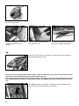
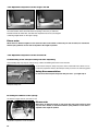
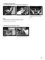
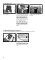
Owner’s Manual
Date of issue: 07-2005
Cabriolet
Corsaire XL
Comfort
Captain XL
Cheetah
Cougar
CX
Table of contents
1.
1.1
1.1.1
1.1.2
1.1.2.1
1.1.2.2
1.1.3
1.1.4
1.1.5
1.1.6
1.1.7
1.2
1.2.1
1.2.2
1.2.3
1.2.3.1
1.2.3.2
1.2.3.3
1.2.4
1.2.5
1.3
1.3.1
1.3.2
1.4
1.5
The Basic Unit .................................................................................................................................................................................................. 4
Assembling the Basic Unit ........................................................................................................................................................................... 4
Assembling the passenger compartment of the Cabriolet, Corsaire XL and Comfort ............................................................. 4
Assembling the passenger compartment of the Captain XL ............................................................................................................ 5
Unpacking and assembling the compartment for the first time ....................................................................................................... 5
Assembling and folding the compartment following initial operation ............................................................................................. 6
Assembling the passenger compartment of the Cheetah, Cougar and CX ................................................................................ 6
Wheel assembly (plastic wheels) on the Cabriolet and Comfort ..................................................................................................... 6
Wheel assembly on the Captain XL, Corsaire XL, Cheetah, Cougar and CX ............................................................................. 7
Fitting the handlebar (for all models except the CX) .......................................................................................................................... 7
Fitting the handlebar on the model CX .................................................................................................................................................... 7
Functions of the Basic Unit .......................................................................................................................................................................... 8
Seat and safety belt ....................................................................................................................................................................................... 8
Climate control in the basic unit ................................................................................................................................................................. 9
Parking brake ................................................................................................................................................................................................... 11
Fitting the parking brake on the Cabriolet, Corsaire XL, Comfort and Captain XL ................................................................... 11
Operating the parking brake on the Cabriolet, Corsaire XL, Comfort and Captain XL ............................................................ 11
The parking brake on the Cheetah, Cougar and CX ........................................................................................................................... 11
Adjustable suspension on the Cougar and CX ................................................................................................................................... 12
Adjustable suspension on the Corsaire XL ............................................................................................................................................ 12
Folding the Basic Unit .................................................................................................................................................................................... 13
Folding the Cabriolet, Corsaire XL, Comfort and Captain XL ........................................................................................................... 13
Folding the Cheetah, Cougar and CX ..................................................................................................................................................... 13
The Rain Cover (accessory, not supplied as standard) ..................................................................................................................... 14
Special Functions of the model CX .......................................................................................................................................................... 14
2.
2.1
2.2
2.3
2.3.1
2.3.2
2.3.3
2.4
2.5
The Bicycle Kit ................................................................................................................................................................................................. 15
Fitting the Reflectors and Safety Flag ...................................................................................................................................................... 16
Fixing the Hitch Arm on the Base (all types of hitch arms) ............................................................................................................... 17
Fixing the Hitch Arm on the Bicycle .......................................................................................................................................................... 17
Fixing the hitch arm with Chariot Universal hitch on the bicycle .................................................................................................... 17
Fixing the hitch arm with Chariot axle hitch on the bicycle .............................................................................................................. 18
Fixing the Weber hitches on the bicycle ................................................................................................................................................. 19
Rear Battery Lights (accessory, not supplied as standard) .............................................................................................................. 19
Safety Instructions for the Bicycle Trailer ................................................................................................................................................ 20
3.
3.1
3.2
The Jogging Kit ............................................................................................................................................................................................... 21
Fitting the Jogging Kit .................................................................................................................................................................................... 21
Safety Instructions for the Jogging Stroller ............................................................................................................................................ 22
4.
4.1
4.2
The Buggy Kit ................................................................................................................................................................................................... 23
Fitting the Buggy Kit ....................................................................................................................................................................................... 23
Safety Instructions for the Buggy .............................................................................................................................................................. 24
5.
5.1
5.2
The Hiking Kit ................................................................................................................................................................................................... 25
Fitting the Hiking Kit ....................................................................................................................................................................................... 25
Safety Instructions for the Hiking Kit ........................................................................................................................................................ 25
6.
6.1
6.2
The Skiing Kit (for the Corsaire XL, Cheetah, Cougar and CX) ..................................................................................................... 26
Fitting the Skiing Kit ....................................................................................................................................................................................... 26
Safety Instructions for the Skiing Kit ........................................................................................................................................................ 27
7.
7.1
7.2
The Walking Kit ............................................................................................................................................................................................... 28
Fitting the Walking Kit .................................................................................................................................................................................... 28
Safety Instructions for the Walking Kit ..................................................................................................................................................... 28
2
8.
General Safety Instructions ....................................................................................................................................................................... 29
9.
9.1
9.2
9.3
9.4
9.5
9.6
Maintenance, Care and Storage of the Chariot CTS .......................................................................................................................... 29
Hitch Arm ........................................................................................................................................................................................................... 29
Wheels ................................................................................................................................................................................................................ 29
Fabric Assembly, Floor Pan ......................................................................................................................................................................... 29
Storage ............................................................................................................................................................................................................... 29
Screws and Fasteners .................................................................................................................................................................................. 29
General Maintenance..................................................................................................................................................................................... 30
10.
Warranty ............................................................................................................................................................................................................ 30
Congratulations on buying this child transporter!
You have decided to buy a product from the CTS-series (Child Transport System) of the Canadian manufacturer Chariot
Carriers Inc.
Your new child transporter stands out because of its excellent quality, user-friendliness, high safety standards and great
versatility.
The Child Transport System enables you go for bike rides, walks or jogging with your children without having to park a
fleet of special vehicles in the garage or basement.
It consists of a basic unit (passenger compartment with chassis, handlebar and two 20” wheels) and at least one of the
following accessory sets:
•
•
•
•
•
•
The bicycle kit (hitch arm, hitch, front, rear and spoke reflectors, safety flag) converts the
base to a bicycle trailer (In Switzerland the bicycle kit comes as standard.)
The jogging kit (16" front wheel with two wheel arms) converts the basic unit to a jogging stroller.
The buggy kit (an 8" buggy twin wheel) converts the basic unit to a buggy.
The hiking kit (drawbar with shoulder strap) converts the basic unit to a hiker.
The skiing kit (skier and drawbar with waist strap) converts the basic unit to a sleigh hiker
(Corsaire XL, Cheetah, Cougar and CX).
The walking kit (drawbar with waist strap) converts the basic unit to a walker.
The following guide describes firstly how to assemble the basic unit using the example of the Corsaire XL. After the
explanation of the various functions you will find the instructions for fitting the accessories.
The guide applies to the other models as relevant. Differences are highlighted separately.
If in doubt ask your specialist dealer!
3
1. The Basic Unit
The assembled basic unit – example Corsaire XL
Parts supplied:
Folded passenger compartment, two 20" wheels, handlebar, parking brake.
Transport safety lock (not Cheetah,
Cougar and CX).
1.1 Assembling the Basic Unit
1.1.1 Assembling the passenger compartment of the Cabriolet, Corsaire XL and Comfort
After releasing the transport safety
lock press the rear of frame using
one hand downwards, with the other
hand push the body upwards.
4
With one hand push the body further
upwards, with the other grip the Wframe and pull backwards. During
this procedure the auto-lock must
audibly engage in the left and right
frame tubes.
Engaged auto-lock
1.1.2 Assembling the passenger compartment of the Captain XL
1.1.2.1 Unpacking and assembling the compartment for the first time
This assembly step may only be carried out by a dealer assembling the trailer for the first time.
On the Captain XL the upper frame tubes on each side of passenger compartment are of two-part design. So as to save
space during transit from the factory to the dealer these tubes are not inserted together.
protective cap
Unpacled from the box, yet
unassembled.
Take off the protective cap before
assembly.
Insert tube ends into one another.
Final assembly
The short piece of tubing at the rear that connects the "W-frame" to the floor pan is of telescopic design.
To continue assembly, first take off the
transport safety lock.
The passenger compartment is then
opened out in line with section 1.1.1. At
the same time the short piece of tubing
illustrated above gets pushed together.
5
Final steps in assembly:
At the clamp, pull tight the strap holding the tops of both side walls together, at the same time as applying pressure with the other hand from the outside.
Pull tight the looped strap.
Pull the 4 rear seat strap-fasteners
tight.
The "Captain XL" is now ready for sale, and from now on, any further folding or opening of the bicycle trailer will not entail reversal of the above steps.
1.1.2.2 Assembling and folding the compartment following initial operation
For assembling and folding the "Captain XL" in the same way as with the Cabriolet, Corsaire XL and Comfort,
see sections 1.1.1 and 1.3.1
1.1.3 Assembling the passenger compartment of the Cheetah, Cougar and CX
Assembling the base: Push the hollow axle with your left hand downwards, and at
the same time push the left frame tube upwards using your right hand. Then pull
the short curved tube backwards with your left hand, pressing against it from
above with your right hand. Repeat this on the right hand side. When pulling the
short, curved frame tube backwards, the auto-lock must noticeably engage.
Auto-lock with release disks
1.1.4 Wheel assembly (plastic wheels) on the Cabriolet and Comfort
Put the passenger compartment on its
side. Insert clevis axle into the opening
of the hollow axle.
Push the wheel axle in as far as it will
go. As you do this, the securing peg of
the hollow axle must audibly engage in
the axle groove of the wheel. Check that
the wheel cannot be pulled off!
Removing the wheel: With one hand
pull the securing peg outwards, with
the other pull the wheel out of the
hollow axle.
6
1.1.5 Wheel assembly on the Captain XL, Corsaire XL, Cheetah, Cougar and CX
Put the basic unit on its side. Press
on the rubber cap of the wheel axle
and insert the clevis axle into the hollow axle until it engages. Repeat this
on the other side.
Check that the wheel cannot be pulled off!
1.1.6 Fitting the handlebar (for all models except CX)
Push the handlebar into the upper open tube ends at the upper section of the carrier. Depress both spring buttons
simultaneously and insert the handlebar fully into the sleeves until the spring buttons engage. The handlebar can be height
adjusted for two different positions: Depress the spring buttons, pull out the handlebar, rotate it 180° and re-insert the
handlebar into the sleeves.
1.1.7 Fitting the handlebar on the model CX
Push the handlebar into the upper open tube ends at the upper section of the
carrier. Depress both spring buttons simultaneously and insert the handlebar fully
into the sleeves until the spring buttons engage.
Safety Recommendation:
In the event of the vehicle tipping over, the handlebar acts as a safety bar. So keep it permanently installed, even when
using the carrier behind a bicycle!
7
1.2 Functions of the Basic Unit
1.2.1 Seat and safety belt
The frames of all Chariot models are stiffened by an additional cross brace, which also serves as an anchor point for the lap
belts and for bracing the seat. This is important when one child is placed in the middle or for two children of different sizes as
the reinforced seat is thus protected against sagging.
With the tried and tested 5-point seatbelt system, children up to 5 years old are securely but comfortably strapped in.
padded
shoulder
harness
buckle of the
shoulder
harness
(under tab)
lap belt
crotch
harness
The seat restraints of the Corsaire XL, Captain XL, Cougar and CX De Luxe versions
come with a padded shoulder harness.
The shoulder harness is fastened using two fastex buckles on the vertical straps
above the seat backrest. So that children can sit comfortably (especially smaller
ones), loosen the fastex buckles of the shoulder harness, place the child on the seat,
guide the shoulder harness over the shoulders of the child and secure it by fastening the fastex buckles.
The crotch strap is fastened using a fastex buckle on the shoulder harness. To fix
the crotch harness-connector in the buckle of the shoulder harness, slightly lift the
tab in the lower part of the shoulder harness.
First adjust the crotch harness so that the V-area of the padded harness is located
in the child’s lower chest area.
Then tighten the shoulder harnesses on both sides equally, so that the child is safely
fastened by the belts. The upper fastening point of the shoulder harness can be
moved upwards on the vertical straps, allowing adjustment to the height of your
child.
Fasten the lap belt!
Tipp:
In order to facilitate entry of the child, the padded shoulder harness can be velcroed in the upper seat area.
shoulder
harness
O-ring
Cabriolet, Comfort and Cheetah: After seating the child, pull the shoulder harness
through the O-ring of the crotch harness. Plug the clip into the buckle of the
shoulder harness.
First adjust the crotch harness so that the O-ring is located in the child’s lower
chest area.
Tighten the shoulder harness securely, so that the child is safely fastened by the
belt.
Fasten the lap belt!
lap belt
crotch
harness
Note:
Always make sure that the child feels comfortable.
If only one child is to be carried, the manufacturer recommends placing him/her in the middle of the seat. This requires the
conversion of one of the shoulder harnesses for use in the middle position (applies to both trailer versions).
For the Corsaire XL, Captain XL, Cougar and CX models it is only necessary to refasten the padded shoulder harness into
both of the middle fastex buckles; for the Cabriolet, Comfort and Cheetah models the shoulder harness needs to be
unstrapped and restrapped in the middle position, see the illustration on the next page.
Safety Recommendation:
Never transport your children without the safety belts being properly and fully adjusted, otherwise your child could be
seriously or even fatally injured in the event of an accident!
8
Thread the end of the harness as
shown through the belt buckles.
Make sure you check the belt buckles
are tight!
Note:
For small children the shoulder padding should be turned down at the top,
otherwise the shoulder strap cannot be
sufficiently shortened.
If necessary, the lower connecting
strap of the shoulder padding can
also be unstrapped and the shoulder
padding can be turned over there as
well.
For all other children, the shoulder
strap can be drawn through the upper
flaps of the padding to prevent the
padding being able to slip to the side.
To reconnect the shoulder strap see
the illustration on the top of the page.
Comparison of different adjustments of
the shoulder padding for children of
different heights.
Note:
The straps displayed in the following illustration are present on all seats and are
there to secure the Chariot baby seat.
There are special assembly instructions
showing how this is fastened.
1.2.2 Climate control in the basic unit
Protection against insects when the
weather cover is rolled up.
On the Captain XL, Corsaire XL,
Cougar and CX the weather cover is
attached by side zips near the
opening.
Triangular ventilating flap, which is
unfolded from the inside
(only Corsaire XL, Captain XL and
Cougar.
9
When fastened over the front the rear
flap acts as a sun shield.
In order to take off the 2-1 cover completely, the handlebar must be
detached.
Mesh cover in the back (Corsaire XL
and Captain XL only).
The model CX has tinted side windows
that can be unzipped and detached.
Tip:
If both zips are half undone, the front half of the side window can be folded back
and inserted behind the rear half.
The floor covering of the Chariot Sport models Cheetah, Cougar and CX forms the seat cover too. This special construction
allows there to be a particularly low centre of gravity and good head room.
Note: Using the Chariot in protracted heavy rain, and/or during longer journeys in the rain, causes saturation of the external
skin. In unfavourable cases moisture can penetrate the seat area, necessitating the wearing of suitable clothing by the children.
The Cougar and CX have removable seat padding so that the children do not
come into direct contact with the floor of the vehicle.
10
1.2.3 Parking brake
1.2.3.1 Fitting the parking brake on the Cabriolet, Corsaire XL, Comfort and Captain XL
Loosen the securing nut of the parking
brake using a 13 mm wrench.
Put the passenger compartment on its
roof (please use a suitable surface)
and loosen both lock nuts off the
brake bolts using an 11 mm wrench.
These bolts are the ones which are
located closest to the rear of the
transporter.
Place one of the two washers on the bolt
of the parking brake and push both
through the hole in the middle of the rear
of the trailer. Push the holes of both
brake arms over the bolt on the right
and left hand side. Tighten the two lock
nuts using an 11 mm wrench so that the
brake arms still have freedom of movement. Finally tighten the nut from the
inside, using the 13 mm wrench. Before
tightening, insert the second supplied
washer under this nut. Again, the bolt
should still have freedom of movement.
1.2.3.2 Operating the parking brake on the Cabriolet, Corsaire XL, Comfort and Captain XL
When the brake is released, the brake
lever points to the right.
When the brake is engaged, the joint of
the brake protrudes over the frame and
the brake lever points to the left hand
side. Both brake arms press on the
tyre.
1.2.3.3 The parking brake of the Cheetah, Cougar and CX
Parking brake: Lock the brake by depressing the brake lever with the foot, release it by pulling the lever upwards with the foot.
Note: Should it not be possible to depress down the brake lever smoothly without resistance, move the transporter slightly
forwards or backwards. Do not forcibly kick the lever downwards, otherwise the locking pins could be bent.
11
1.2.4 Adjustable suspension on the Cougar and CX
Chariot adjustable suspension (CAS): After loosening the knob it is possible to
move the bracket, which surrounds both leaf springs. The more you slide this
bracket towards the wheel axis, the stiffer the suspension becomes (see diagram
containing weight details on the upper spring).
Please note:
Where there are different weights on each of the two sides of the vehicle or where only one side is loaded, we recommend
that the spring stiffness on each side be adjusted to the weight in question.
1.2.5 Adjustable suspension on the Corsaire XL
A. Dismantling of the transport safety lock after unpacking
This assembly step may only be carried out by a dealer assembling the trailer for the first time.
To remove the transport safety lock press down on the trailer from above so as to
loosen the suspension. Extract the transport safety lock from one side using pliers.
Safety Recommendation:
Do not extract the transport safety lock with your hand – you might trap it!
Transport safety lock
B. Setting the stiffness of the springs
As with the Cougar and CX, see section 1.2.4
Please note:
Where there are different weights on each of the two sides of the vehicle or where
only one side is loaded, we recommend that the spring stiffness on each side be
adjusted to the weight in question.
Adjustable suspension on the Corsaire XL
12
1.3 Folding the Basic Unit
1.3.1 Folding the Cabriolet, Corsaire XL, Comfort and Captain XL
Auto-lock with release disks
Releasing the disks of the auto-lock.
To fold the base, release both disks
simultaneously and push the W-frame
forwards.
Tip:
Folding the transporter is easier with the parking brake engaged.
To remove the wheels see paragraph 1.1.3
1.3.2 Folding the Cheetah, Cougar and CX
To fold, release the locks on each side
separately.
Pull the auto-lock disk and press the
short, curved frame tube forwards.
13
1.4 The Rain Cover
(accessory, not supplied as standard)
For each Chariot CTS a seamless rain
cover is available.
To fit the rain cover on the upper frame,
remove the handlebar and push the two
seals, which are welded round the holes
of the rain cover (or the elastic loops,
depending on the model) over the tube
ends. Re-attach the handlebar (see
section 1). Attach the rain cover on the
lower frame exactly as the combi-cover,
which is supplied as standard.
On the Cheetah, Cougar and CX two
elastic ribbons, situated in the right and
left lower area of the cover, are pulled
round the horizontal rectangular tube
and placed round the nut of the cover
fastening.
The rain cover is fitted correctly, when
the printed writing can be read from
the outside.
1.5 Special Functions of the model CX
This model is equipped as standard with a handlebar bag, which can also be used as a child rucksack.
The handlebar bag is attached to a
specially designed clip at the rear end
of the passenger compartment as well
to the handlebar itself by means of two
straps.
14
2. The Bicycle Kit
The assembled bicycle trailer (base +
bicycle kit) – example Cougar1
For your Chariot CTS there is a choice of three different bicycle hitch arms with different hitches. Fitting any of the hitch arms
on the base takes no time at all and is the same for all hitch arms.
Safety Recommendation:
All aluminium hitch arms have been tested for safety by the manufacturers. These tests include functional tests as well as
load and fatigue tests. We only use hitch arms which have withstood these tests without any problem.
Because it is difficult to determine the exact life time of a bicycle trailer and to know the actual loads to which the hitch arms
will be subjected during this time, there does remain a risk in theory – and this cannot be excluded with absolute certainty –
that even a hitch arm which has undergone testing could fail, if it is put under extreme load for several years.
To rule out this theoretical risk, we have limited the period of use for all hitch arms to a maximum of 3 years.
Please replace your hitch arm after 3 years at the most and draw attention to this safety recommendation should you sell
the trailer.
Parts supplied:
Bicycle kit "Uni”: Chariot hitch arm
with universal hitch, front, rear and
spoke reflectors, safety flag.
Parts supplied:
Bicycle kit "Axis”: Chariot hitch arm
with axle mounted hitch and quick
release, front, rear and spoke reflectors, safety flag.
Parts supplied:
Bicycle kit "Weber”: Weber hitch arm
without hitch, front, rear and spoke
reflectors, safety flag. You can either
choose the Weber hitch with adjustable kickstand (Weber B) or the Weber
hitch for rear-axle attachment (Weber
E) – see paragraph 2.3.3.
15
2.1 Fitting the Reflectors and Safety Flag
When using the transporter as a bicycle trailer you must attach the front, back and spoke reflectors as well as the safety flag.
Spoked wheels on the Corsaire XL, Captain XL, Cougar and CX
Position the spoke reflector between
two outer spokes and an inner spoke
in such a way that the inner spoke lies
in the guide slot of the reflector.
Guide the plastic holder with its slot
over the inner spoke into the hole of
the reflector and secure by tightening
it a quarter turn using a screwdriver.
Fit two reflectors on each wheel (as
shown to the right and left of the valve).
Plastic wheel on the Cabriolet, Comfort and Cheetah. Screw two reflectors onto
each wheel at the corresponding brackets.
For fixing the reflectors to the passenger compartment you need a Philips
screwdriver.
Fit the red reflectors in the rear
grommets.
Fit the white reflectors in the front
grommets.
Assemble the flag, push it on the left hand side through the loop of the weather
cover and insert it in the corresponding flap (in countries where the traffic drives
on the left the safety flag must be inserted in the flap on the right hand side).
For the Cheetah, Cougar and CX the safety flag is inserted in a hole in the
plastic cap of the rear frame tube (not illustrated).
16
2.2 Fixing the Hitch Arm on the Base (all types of hitch arms)
To insert the hitch arm depress the smaller knob and push the hitch arm in, until
the big button engages (Nos. 1 to 4).
Insert the securing pin into the rear hole
of the hitch arm attachment bracket and
push against the pressure of the springloaded ball as far as it will go.
Safety note!
The securing pin must be attached as well as the ‘click system’ of the bicycle hitch arm! A hitch arm that has not been secured properly can come loose during travel. This is extremely dangerous and can result in serious or fatal injury.
2.3. Fixing the Hitch Arm on the Bicycle
2.3.1 Fixing the hitch arm with Chariot Universal hitch on the bicycle
Note:
The Chariot Universal hitch is only suitable for bicycles with a round or oval chain stay with a tube diameter between 14 mm
and 26 mm.
Guide the open hitch under the left
hand side chain stay. (If a kick stand is
attached to the rear of the bicycle, this
stand needs to be removed.) Both rubber inserts of the hitch must be tight
against the chain stay.
Guide the quick release (Q.R.) lever over
the chain stay and press it into the groove of the hitch. Close the lever downwards. The securing pin of the Q.R. lever
(see illustration below) must noticeably
engage.
If the hitch can still be moved, then open
the Q.R. lever
(depressing the securing pin) and rotate
the lever clockwise.
Keep repeating this step, until you can
clearly feel resistance when tightening
the Q.R. lever and the hitch cannot be
moved anymore or be twisted out of
position.
Please note:
Never turn the Q.R. lever when in the
groove, only when open!
Safety Recommendation:
Always attach the safety strap to the
chain stay!
Put the safety strap around the bicycle
chain stay and attach the safety clip to
the D-ring of the hitch arm
Detaching the coupling
see next page
17
Detaching the coupling
Depress the securing pin of the Q.R.
lever, open the lever, push the axle
upwards and remove the coupling
downwards. Remove the safety strap.
2.3.2 Fixing the hitch arm with Chariot axle hitch on the bicycle
Parts supplied:
Aluminium coupling for attachment on
the rear axle; quick release skewer
Fitting the hitch on a bicycle with quick
release axle on the rear wheel
Remove the existing quick release skewer. Loosen the nut of the Chariot
quick release.
Push the Q.R. axle through the hitch
and then through the hollow axle of the
bicycle’s rear wheel. The opening for
the hitch ball must point forward.
Screw on the Q.R. nut on the other
side of the Q.R. axle. Both Q.R. springs
must be located on the Q.R. axle
in such a way that the narrower side of
the spring points towards the centre of
the rear wheel hub.
Close the Q.R. lever with the end of the
lever pointing upwards. In this position
there is enough space to insert the
securing pin. Please read also the section "Jogging Kit”, which contains further instructions on how to correctly
operate a Q.R. lever.
Fitting the hitch cups on a bicycle with
solid rear axle (e.g. all bicycles with
hub gearing)
Remove the existing nut and washer on
the left hand side of the wheel axle.
Place the aluminium hitch cup with its
opening pointing forward on the wheel
axle and screw on the axle nut.
Depending on the hub type, the existing washer needs to stay on the
frame (for fitting the hub, as well as torque values for fastening the axle nut,
see manufacturer’s instructions).
Safety Recommendation:
The axle nut must be tightened on the axle thread by at least 5 full turns, so that an adequate clamping force is ensured. A
thread which is too short can lead to accidental loosening of the rear wheel and thereby to damage and accidents.
If in doubt ask your specialist dealer!
18
Attaching the trailer (identical for quick
release axle and solid axle): Insert the
hitch ball, which is attached to the
hitch arm, from the front into the aluminium hitch cup.
Pull the hitch ball to the end of the
hitch cup.
Push the securing pin from the top
through both holes of the aluminium cup
and secure the pin by pulling the hole of
the elastic ribbon over the protruding
end of the pin.
Safety Recommendation:
Always attach the safety strap to the
chain stay!
Put the safety strap around the bicycle
chain stay and attach the safety clip to
the D-ring of the hitch arm
Warnings regarding both Chariot hitches:
When turning round or manoeuvring the outfit, the angle between the towing bicycle and the trailer must not exceed 90°,
otherwise the hitch ball could be damaged (overstretched).
2.3.3 Fixing the Weber hitches on the bicycle
Please read carefully the comprehensive manufacturer’s instructions which are
supplied by Weber with the hitch with adjustable kickstand (Weber B) and with the
Weber hitch for rear-axle attachment (Weber E).
2.4 Rear Battery Lights
(Accessory, not supplied as standard)
In the upper area of the rear cover there is a sewn-on webbing strap on the right
and on the left for attaching rear battery lights. When using the trailer in the dark,
an additional rear light is required by law. If only one battery light is attached, it
needs to be on the left hand side in direction of travel (in countries where the traffic drives on the left the battery light must be attached to the webbing strap on the
right hand side). Flashing lights are prohibited in some countries, e.g. in Germany.
Note:
Please ensure when buying lights that they conform to the appropriate legal
requirements of the country they are used in and also bear an approval mark
(e.g. K-mark in Germany).
19
2.5 Safety Instructions for the Bicycle Trailer
(see also section 8 "General Safety Instructions")
•
•
•
•
•
•
•
•
•
•
•
•
•
•
•
•
•
•
•
•
•
•
•
•
•
•
•
•
20
Before use read the User Guide carefully
The bicycle rider must be older than 16 years.
Before setting off, check that the trailer cannot come into contact with parts of the bicycle, such as pedals and brakes etc.
Before setting off, ensure correct assembly of all components, in particular wheels and hitch arm.
Remember that the running characteristics of your bicycle will be changed when towing a trailer, and that greater demands
will be made of the brakes and load bearing capabilities of the frame. If in doubt ask your specialist dealer.
We recommend that you fit mudguards and rear view mirrors to your bicycle
Only children that can sit without support may be carried, unless a Chariot-approved child seat is used.
Always avoid going over obstacles (kerbs etc.) with one wheel
of the trailer only, especially in bends – the trailer might tip over,
even at a very low speed!
In the event of the vehicle tipping over, the handlebar grip acts as a
safety bar. So keep it permanently installed, even when using the
transporter behind a bicycle!
Attach or detach the trailer to/from the bicycle only when unladen.
Make sure the hitch is safely attached. A hitch, which is incorrectly fitted, could become loose and could either slip
sideways into the spokes or forwards in the direction of the bottom bracket during braking. In both cases there is
considerable danger that the cyclist and the trailer occupants will get injured. If in doubt ask your specialist dealer!
The securing pin must be attached as well as the ‘click system’ of the bicycle hitch arm! A hitch arm that has not been
secured properly can come loose during travel. This is extremely dangerous and can result in serious or fatal injury.
Before starting, always check that the hitch arm is properly secured by the safety strap, which is screwed on the
hitch arm attachment bracket.
The maximum permissible speed for towing a Chariot bicycle trailer is 25 km/h. Only take bends at walking pace.
Cycle carefully and avoid full braking. When towing a trailer and decelerating using the front brake, the bicycle, especially
its fork, are put under high loads.
It is recommended that rider and trailer occupants wear approved cycle helmets.
BNever transport your children without the safety belts being properly and fully adjusted, otherwise your child could be
seriously or even fatally injured in the event of an accident!
Only cyclists who are experienced and strong enough may tow child-carrying trailers.
Bicycle trailers must not be towed by motorized two-wheelers.
Check tyre pressure before each ride. Keep tyres inflated to 30-35 psi (2.1 - 2.5 bar).
When parking the outfit make sure it cannot tip over. Attaching a trailer changes the bicycle’s centre of gravity, so that
certain types of kick stands, especially double leg kickstands, cannot be used in connection with a trailer. The bicycle could
tip over, or children, who are entering or leaving the trailer, could get injured. Tipping over may damage the trailer, hitch arm
or the trailer hitch.
Always attach the safety flag to the basic unit before setting off.
Trailers, even when folded, must not be transported on the roof of a vehicle.
When used in the dark, bicycle and trailer must be equipped with the correct lighting.
Never ride without the weather cover, otherwise your child may be injured by insects, dirt or grit thrown up from the road.
When converting your Chariot from operation as a buggy to use as a trailer behind a bicycle, the buggy wheels need to
be inserted upside down into the hitch arm attachment bracket and be secured from below using the star knobs.
The period of use for all hitch arms is limited to a maximum of 3 years.
Please replace your hitch arm after 3 years at the most and draw attention to this safety recommendation should you
sell the trailer.
Where there are different weights on each of the two sides of the vehicle or where only one side is loaded, we recommend
that the spring stiffness on each side be adjusted to the weight in question
3. The Jogging Kit
Parts supplied:
Jogging kit: 16” wheel and two wheel
arms with ‘click system’
The assembled jogging stroller (base + jogging kit) – example Cougar1
3.1 Fitting the Jogging Kit
Hold the wheel arm with the bar curving towards the centre of the transporter and the wheel slot pointing
downwards. Push the arm into the
hitch arm attachment bracket.
To insert the wheel arms depress the
smaller knob and push the wheel arm
in until the big button engages.
Push the Q.R. axle through the hollow wheel axle and screw on the nut. Both Q.R. springs must be located on each side of
the Q.R. axle in such a way that the narrower side of the spring points towards the centre of the rear wheel hub.
Tip the transporter backwards and rest it on the handlebar. Then insert the wheel
into the slots.
Close the Q.R. lever.
In order to ensure that the hub is clamped sufficiently in the slots, the Q.R. lever must begin gripping as it moves from the open to
the middle position, and approaching the closed position you should clearly feel resistance as you tighten. If it is too easy or too
difficult to move the quick release lever, tighten or loosen the Q.R. lock nut on the other side of the hub.
21
Safety Recommendation:
When using the carrier as a jogger always put the wrist strap, which is fastened
securely on the left rear frame tube, around your wrist. This prevents the transporter from accidentally rolling.
On the Cheetah, Cougar and CX you
may conveniently attach the wheel of
the jogging kit to the carrier if the
Chariot CTS is to be used in any form
other than a jogging stroller.
Note: First of all draw the upper belt
tight. Then secure the wheel using the
right hand side and left hand side belts.
The wheel arms can be placed in the
rear bag.
To help the vehicle run in a straight line:
The dropouts of the wheel arms are screwed on. After loosening both screws, the
aluminium elbow near the two slots can be moved. This is possible on both the
right and the left side. If the jogging stroller is pulling to the right, the aluminium
elbow on the right hand side must be moved forwards, and the one on the left
hand side backwards (and vice versa).
Note:
Please ensure that your child does not stand on the wheel arms when entering or leaving the transporter. If at any time you
stop, do not allow anyone to sit on the wheel arms. Applying a load on either wheel arm causes the riveted aluminium axle
sockets to loosen.
3.2 Safety Instructions for the Jogging Stroller
(see also section 8 "General Safety Instructions”)
•
•
•
•
22
Do not inline skate with the stroller.
If you leave the stroller standing, always secure it with the parking brake.
When pushing the stroller, always use the wrist safety strap.
The brakes should not be used to control a rolling carrier to a halt.
4. The Buggy Kit
Parts supplied:
Buggy twin wheels
The assembled buggy (base + buggy kit) – example Cougar1
4.1 Fitting the Buggy Kit:
protector, this means the wheel bolt is
to be held tightly when turning off the
star knob.
When fitting the star knob all that is
needed is that the buggy wheel be
pressed hard on the ground by applying pressure on the hitch arm attachment bracket. Repeat this on the other
side.
Unscrew the star knob of the buggy
wheel and insert the wheel bolt from
below through the large hole in the
hitch arm attachment bracket.
Screw the star knob onto the threaded
area of the wheel bolt and tighten
securely. Repeat this on the other side.
The star knob has a plastic thread.
Safety Recommendation:
When using the carrier as a buggy always put the wrist strap, which is fastened securely on the left rear frame tube, around
your wrist (see illustration for jogging kit).
If you wish to use your Chariot CTS in
any other form than a buggy, it is very
easy to take the buggy wheels with
you. Simply insert them upside down
into the hitch arm attachment bracket
and secure them from below using the
star knobs. The fork arms need to point
forwards.
The star knob has a plastic thread protector, this means the wheel bolt is to
be held tightly when tightening up the
star knob. When fitting the star knob all
that is needed is that lateral pressure
be applied to the buggy wheel so as to
slightly twist the axle.
The fork of the buggy twin wheel must
sit in both guide grooves of the hitch
arm attachment bracket so that it cannot be turned.
23
4.2. Safety Instructions for the Buggy
(see also section 8 "General Safety Instructions”):
•
•
•
•
24
If you leave the buggy standing, always secure it with the parking brake.
When pushing the buggy, always use the wrist safety strap.
The brakes should not be used to control a rolling carrier to a halt.
When converting your Chariot from operation as a buggy to use as a trailer behind a bicycle, the buggy wheels need to
be inserted upside down into the hitch arm attachment bracket and be secured from below using the star knobs.
5. The Hiking Kit
Parts supplied:
Drawbar with shoulder strap.
The assembled hiker (base + hiking kit) – example Cougar1
5.1 Fitting the Hiking Kit:
Push the short end of the drawbar into
the attachment bracket. Once the holes
of the attachment bracket and the drawbar are aligned with each other (the end
of the drawbar is visible), push the securing pin from below through bracket and
drawbar and lock it by pushing the clip
over the pin.
The holes in the drawbars are larger
than the safety snap pins, so that the
drawbars can turn slightly around their
longitudinal axis (in order to adapt to
narrow or wide hips).
The shoulder strap, which is attached
in a similar way to that of a rucksack,
can be adjusted in three positions: at
the chest strap at the front,
at the back strap on top for adjusting
the height of the hip strap
and at the hip strap itself.
5.2 Safety Instructions for the Hiking Kit
(see also section 8 "General Safety Instructions”):
•
Always make sure that the safety snap pin is fully pushed in and secure, so as to prevent the transporter from accidentally rolling.
25
6. The Skiing Kit
(for the Corsaire XL, Cheetah, Cougar and CX ):
Parts supplied:
Skier and drawbar with waist strap
The assembled sleigh hiker (base + skiing kit) – example Cougar1
6.1 Fitting the Skiing Kit:
Fitting the skiing kit: Firstly, remove the
wheel by pressing on the axle knob.
Insert the skier into the hollow axle
while depressing the axle knob and
ensure that the axle safely engages.
Slide the drawbar into the drawbar
attachment bracket.
Once the holes of the attachment brakket and the drawbar are aligned with
each other push the securing pin from
below through bracket and drawbar and
lock it by pushing the clip over the pin.
26
The drawbar is adjustable for three
lengths. Pull out the inner tube and
insert the securing pin when the holes
of inner and outer tube are aligned with
each other.
If required the waist belt can be adjusted tighter. To do this loosen one or
both mounting bolts and screw them
into the free grommets.
The combined use of skiing kit and
jogging kit allows it to be used as a
sleigh hiker for pushing!
6.2 Safety Instructions for the Skiing Kit
(see also section 8 "General Safety Instructions”):
•
•
•
•
•
•
•
Only an experienced skier should use the carrier with skiing kit.
Take the carrier with skis for a practice run (weighted with a load greater than that expected when carrying children and
cargo) over more varied terrain than you expect to ski, until you are skilled in handling the carrier.
Never use the skiing kit for downhill skiing and never tow it behind a snow mobile.
Use extreme caution on hills, aggressive trails, and when stopping.
Regularly monitor your children to ensure they are comfortable and warm.
Make sure the length of your drawbar is adjusted correctly, to ensure that your skis or poles will not be in contact with
the carrier.
Always make sure that the safety snap pin is fully pushed in and secured, so as to prevent the transporter from
accidentally slipping.
27
7. The Walking Kit
Parts supplied:
Drawbar with waist strap
The assembled walker (base + walking kit) – example Cougar1
7.1 Fitting the Walking Kit:
The walking kit consists of the skiing kit drawbar and waist strap. Please follow the assembly instructions as for the skiing kit.
(see section 6)
7.2 Safety Instructions for the Walking Kit
(see also section 8 "General Safety Instructions”):
•
28
Always make sure that the safety snap pin is fully pushed in and secured, so as to prevent the transporter from
accidentally rolling.
8. General Safety Instructions:
Irrespective of any special use, attention should always be paid to the following instructions:
•
•
•
•
•
•
•
•
•
•
Do not try to make any alterations to the carrier that are not described in this Owner’s Manual.
Do not exceed the maximum load of 45 kg (99 lbs.) for two-seater models and of 34 kg (75 lbs.) for the one-seater
models. These loads include luggage.
Only transport children under the age of seven (please observe the maximum load of 45 kg for the two-seater).
Do not carry more than two children in the carrier.
Children should be old enough to wear a helmet and be able to sit upright without outside help, or they should be
strapped in a specially fitted baby seat (accessory).
The child’s head, including helmet, must not project above the upper frame.
Make sure that neither the child’s limbs, clothing, shoe straps, nor any toys come into contact with the moving parts of
the carrier.
Passengers must always wear seat belts.
Take care when travelling over uneven surfaces. If the carrier is moved over an obstacle with one wheel only there is a
danger of tipping it over, regardless of speed.
In the event of the vehicle tipping over, the handlebar grip acts as a safety bar - so keep it permanently installed, even
when using the carrier behind a bicycle!
Never leave children unattended in carrier.
Always check on a regular basis that your children are comfortable at the given temperatures.
9. Maintenance, Care and Storage of the Chariot CTS
9.1 Hitch Arm
Check the hitch arm regularly for signs of damage (e.g. cracks). If there is any kind of damage whatsoever to the hitch arm,
then it must be replaced so as to prevent failure and the resulting risk of accident.
If in doubt, consult your specialist dealer.
In the interests of safety, the hitch arm should be replaced every three years (see also Section 2)
9.2 Wheels
Have the wheels (tyres, rims, tension of spokes, axle bearing) checked by your Chariot specialist dealer at least twice every
year.
Clean the wheels regularly and give them a protective wax, particularly just before the onset of Winter.
9.3 Fabric Assembly, Floor Pan
Clean the fabric assembly and floor pan with domestic soap or a mild cleansing agent and warm water. Never use thinners or
benzine.
9.4 Storage
Store your Chariot CTS in a dry and well-ventilated place. Before storing your carrier, it should be dry to prevent the growth of
mould and the formation of marks from mildew. Expose your carrier as little as possible to direct sunlight to prevent colours
fading. Do not store the trailer coupled to the bicycle over a long period of time.
Safety Recommendation:
As well as rubber, tyres contain many chemical substances which improve their physical characteristics. In unfavourable circumstances, these substances may lead to staining of the transparent side and front panels of the child transporter. For this
reason, always store wheels in such a way that they do not come into contact with these transparent panels.
9.5 Screws and Fasteners
Make regular checks that the screws and nuts are fully tight and that all safety fasteners are correctly fitted.
29
9.6 General Maintenance
Look after your trailer. All aluminium parts, chrome or galvanised parts (including all screw connectors) should be regularly
cleaned and protected using standard products for this purpose. Ask your specialist dealer about suitable products for
protecting your trailor.
10. Warranty
The statutory warranty covers defects. Damage resulting from improper use, use of force, lack of maintenance, or normal wear
and tear, is excluded from such a statutory defect warranty.
The period of statutory warranty depends on the law of the country in question.
Our products have components or parts which are also subject to natural wear and tear arising from normal use, depending
very much on the type and degree of use and also how well the product has been serviced and maintained.
In particular where there has been a lot of use (day in day out and in all kinds of weather), individual parts or components
can reach their wear limit before the statutory guarantee period has expired. Just because a product has become prematurely
worn because of use, it does not automatically mean the product is defective.
For your information we have therefore listed in the following table the important parts affected by wear and tear, and have
named typical contributing factors relating to use, which may considerably influence wear limit.
Maintenance and care of bicycle trailers and jogging strollers:
Irrespective of
• Type of use
• Intensity of use
• Care and maintenance
functional-related wear occurs in bicycle trailers or jogging strollers in the components and parts listed in the following table.
Reaching the wear limit depends on how well the users have looked after and maintained the product as well as the particular
type and intensity of use such as:
•
•
•
•
•
Mileage in km
Loading of:
Passengers
Baggage
Type of ride:
Degree of acceleration and braking
Fast cornering
Effects of the weather:
UV rays
Humidity
Dirt
•
•
Temperature
Salty air
Contact with salt water
Roads gritted with salt
Storage
Level of maintenance:
Service intervals
Means of maintenance
Storage
Servicing and inspection work
Please look at the following table: ‘Wear factors’. You can see from this table which factors particularly affect the wear and
tear on individual parts.
30
Factors, which particularly increase wear on bicycle trailers
and jogging strollers:
Rims, hubs
& spokes
xx
xx
Baggage
xx
x
x
x
xx
xx
Type of ride
Degree of acceleration and braking
xx
x
xx
xxx
xxx
xx
x
xx
xxx
Fast cornering
x
Hitch arm,
Clutch
Brake cable
(stroller)
x
Tyres*5
Brake pads
(stroller)
x
x
Windows
x
Passengers
Seat
xx
Wear factors
Loading of:
Textile floors
& side walls
Fabric body
Parts
xxx
Influence of
UV rays
xx*1
x
xx
xx
the weather:
Humidity
xx*3
xx
xx
x
Dirt
xx
xx
xx
xx
Temperature
x*6
x
x*6
xx*6
Salty air
x
x
xx
x
x
xx
xx
x
xx
Contact with salt water
xx
xx
xx
xx
x
xx
xxx
x
xx
Roads gritted with salt
xx
xx
x
x
xx
xxx
x
xx
x*3
x*3
x*3
Storage
x*3
xx*2
x
xx
x
x
xx
x
x
x
x
x*4
Influences on wear and tear:
x:
Moderate effect on wear and tear
xx: Strong effect on wear and tear
xxx: Considerable effect on wear and tear
*1
*2
*3
*4
*5
*6
-
If at all possible, avoid exposure to strong sun light
If at all possible, avoid long exposure to sun light
Avoid mould forming by storage in a dry place
No wear and tear if stored in a hanging position
Regularly check the air pressure
Cold: At temperatures below 0°C the material gets brittle and may crack.
31
Date of issue: 07-2005
www.chariotcarriers.com