1
User Documentation.
Version V2.31.1
Programming System
Integrated Service Technical Application
Programming (ISTA/P).
BMW Group
www.bmwicom.net
ISTA/P - User Documentation
Vehicle Programming in Service Applications
VP-30
Register/Index: 11
900/08-11
Page 2
of 131
Worldwide
All countries
Date:
09/2008
Version V2.31.1
ISTA/P User Documentation
BMW, MINI and Rolls-Royce
Page
Changes to ISTA/P and the user documentation
General information on ISTA/P
Installations for using ISTA/P
ICOM (Integrated Communication Optical Module)
Preparing vehicle programming and finishing off
Starting an ISTA/P session
Retrofitting and modifications
Vehicle and Key Memory (CKM)
ISTA/P Data management
Programming procedure for model series E31, E32 and E34
Programming procedure for the model series E36 to E93
Programming procedure for model series F01 and F02
Programming BMW navigation systems
Locations of OBD and MOST in BMW vehicles
Programming procedure MINI
Programming MINI navigation systems
MINI Retrofitting and conversions
Locations of OBD and MOST of MINI model series
Programming procedure Rolls-Royce
Glossary
3
4
6
8
12
16
25
31
34
39
42
61
80
83
86
105
108
109
111
129
Copyright © BMW AG/ISTA/P - User Documentation
Version V2.31.0/August 08
www.bmwicom.net
ISTA/P - User Documentation
Vehicle Programming in Service Applications
Page 3
of 131
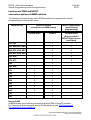
Changes to ISTA/P and the user documentation
The current ISTA/P user documentation is based on the following software media:
Software medium
Version
ISTA/P (DVD)
ISSS Basic (DVD)
ISIS Update (DVD)
BMW Navigation (CD)
SWT (enable code) (DVD)
V2.31.1
V2.6.0
V2.6.0
31.0 (part number 01 59 0 141 891, index u)
1.1 (part number 01 99 0 036 166)
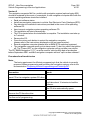
The F01 and F02 represent a new generation of vehicles that not only feature new
functions but are also equipped with a new control module architecture and a new
system network structure (BN2020).
The previous programming system Progman has been replaced by ISTA/P. In addition to
containing the complete scope of vehicle programming, ISTA/P also features new
functions, making it well equipped to effectively meet future vehicle programming
requirements in service applications.
Compared to Progman, the introduction of ISTA/P has given rise to the following new
features:
•
•
•
•
•
•
•
Configurable measures plan with graphic and tabular representation
Detailed display of control module status
Entry of enable codes/vehicle orders from any point in the workshop with access
to the workshop information system/ISTA/P
Subsequent expansion and adaptation of measures plan
Generation of control module order list whenever hardware needs to be replaced
Interruption of a session if spare parts are not available
Display of last Progman or ISTA/P version with which the vehicle was
programmed.
Copyright © BMW AG/ISTA/P - User Documentation
Version V2.31.0/August 08
www.bmwicom.net
ISTA/P - User Documentation
Vehicle Programming in Service Applications
Page 4
of 131
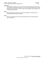
General information on ISTA/P
The ISTA/P programming system is an ISPI application and stands for Integrated Service
Technical Application/Programming. ISTA/P is used to process all coded, programmed
and enable-dependent control modules in BMW Group vehicles.
Important note:
Vehicle programming/coding is permitted only when:
•
•
•
•
•
A test module in the ISTA workshop system requests programming
A BMW-approved fault elimination measure requests vehicle programming
Retrofitting or conversion are required
Required as part of a technical campaign
Control modules need to be replaced.
The ISTA/P start page provides an overview of the number of current programming
sessions and the progress of updates.
User information
After ISTA/P has been installed, this user documentation explains how this system is
used in the vehicle programming procedure in the workshop. This handbook describes
the fundamental functions of ISTA/P.
Knowledge of how ISPI components interact in the workshop network is of central
importance when working with ISTA/P. Detailed information on each individual system
and on network issues can be found in the respective handbooks:
ISTA
ISIS
ICOM
ISPA
ISID
WSM
User instructions
User documentation
Vehicle interface handbook
Technical administrator handbook
Device description handbook
User guide
The handbooks are available on the current version of the "Documentation DVD".
Copyright © BMW AG/ISTA/P - User Documentation
Version V2.31.0/August 08
www.bmwicom.net
ISTA/P - User Documentation
Vehicle Programming in Service Applications
Page 5
of 131
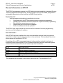
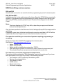
The SSS becomes an ISSS by installing SSS Basic (DVD) via the DVD drive of the SSS.
A screen must be connected during the installation procedure. The ISTA/P data DVD is
installed on the ISIS level.
The ISTA/P application is resident in the ISSS.
The ISSS is integrated in the system network of the ISIS. Updates take place via
JETstream or DVD on the ISIS.
Copyright © BMW AG/ISTA/P - User Documentation
Version V2.31.0/August 08
www.bmwicom.net
ISTA/P - User Documentation
Vehicle Programming in Service Applications
Page 6
of 131
Installation for using ISTA/P
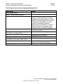
The following steps must be performed as part of the installation of the ISSS Basic DVD:
User action
Switch on ISSS.
Load current ISSS Basic DVD in the DVD
drive.
Switch ISSS off and back on again.
Result
Basic installation then runs automatically.
After a short time, the following message
appears: "Basic DVD installation in
progress. This will take approx.
20 minutes."
The DVD drive opens automatically.
The message appears: "Please remove
Basic DVD and close tray."
Remove the Basic DVD from the DVD drive
and close again.
The system will restart on completion of
the basic installation procedure.
Following basic installation, the ISSS must again be logged on to the ISIS and registered.
Overall system administration takes place directly via WSM. Please refer to the WSM
User Guide for further information on installation and administration.
Copyright © BMW AG/ISTA/P - User Documentation
Version V2.31.0/August 08
www.bmwicom.net
ISTA/P - User Documentation
Vehicle Programming in Service Applications
Page 7
of 131
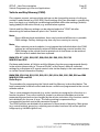
Note:
For ISTA/P to be used, the version of the basic installation on ISSS and the
version of the ISTA/P DVD must be mutually compatible. Each new ISTA/P DVD
contains a reference to basic installation requirements.
Copyright © BMW AG/ISTA/P - User Documentation
Version V2.31.0/August 08
www.bmwicom.net
ISTA/P - User Documentation
Vehicle Programming in Service Applications
Page 8
of 131
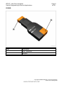
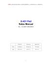
ICOM (Integrated Communication Optical Module)
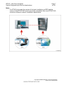
The ICOM is the data interface to the vehicle and is the successor to OPS (Optical
Programming System) and OPPS (Optical Testing and Programming System). OPS and
OPPS are not supported by ISTA/P. Three different ICOM interfaces are available, with
which all BMW Group vehicles can be processed.
ICOM A
Index
Description
1
Network connection
2
USB port
3
OBD connector
Copyright © BMW AG/ISTA/P - User Documentation
Version V2.31.0/August 08
www.bmwicom.net
ISTA/P - User Documentation
Vehicle Programming in Service Applications
Page 9
of 131
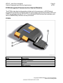
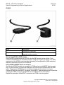
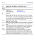
ICOM B
Index
Description
4
MOST connector
5
USB port
Copyright © BMW AG/ISTA/P - User Documentation
Version V2.31.0/August 08
www.bmwicom.net
ISTA/P - User Documentation
Vehicle Programming in Service Applications
Page 10
of 131
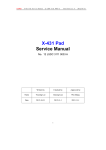
ICOM C
Index
Description
6
Connector for OBD port
7
Diagnosis head connector
Connecting ICOM to OBD socket
Plug the OBD connector on the ICOM A into the OBD socket on the vehicle. Then
connect the ICOM A to the workshop network using the network connector. The OBD
connector on the ICOM A can be angled, allowing it to be adjusted for OBD sockets at
different installation locations in the vehicle.
Using ICOM at MOST direct access port
Also use the ICOM B module to connect the ICOM to the vehicle MOST direct access
port. For this purpose, connect the USB ports of ICOM A and of ICOM B with the USB
cable. Then connect ICOM A to the workshop network via the network connector.
Connect ICOM B via the MOST connector to the MOST direct access port of the vehicle
and plug the OBD connector of ICOM A into the OBD socket on the vehicle.
Repeat the procedure if the MOST connection or ICOM is not recognized.
Copyright © BMW AG/ISTA/P - User Documentation
Version V2.31.0/August 08
www.bmwicom.net
ISTA/P - User Documentation
Vehicle Programming in Service Applications
Page 11
of 131
Using ICOM at 20-pin diagnosis plug
Use the ICOM C module to connect the ICOM to the 20-pin diagnosis plug on the
vehicle. For this purpose, plug the OBD connector into the OBD port on the ICOM A and
connect the diagnosis head connector to the 20-pin diagnosis plug on the vehicle.
Copyright © BMW AG/ISTA/P - User Documentation
Version V2.31.0/August 08
www.bmwicom.net
ISTA/P - User Documentation
Vehicle Programming in Service Applications
Page 12
of 131
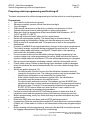
Preparing vehicle programming and finishing off
The basic requirement for efficient programming is that the vehicle is correctly prepared.
Preparations:
•
Park vehicle on flat and even ground
•
Wherever possible, protect vehicle from direct sunlight
•
Turn off engine
•
Shift manual transmission to Neutral or automatic transmission to Park.
•
Activate electromechanical parking brake or apply parking brake
•
Make sure that the temperature of the transmission fluid is between -40 °C
(-40 °F) and 85 °C (185 °F)
•
Switch off all electric loads, lights and turn signal lamps
•
Switch off wiper/washer system. The wipers may be actuated during
programming and initialization. Make sure that the wipers can move freely
•
Make a note of all stored radio and TV frequencies as well as the navigation
destinations
•
Connect up a BMW Group-approved battery charger in the engine compartment.
The battery charger connected during programming must be run in "external
power supply mode with battery connected". Please refer to the operating
instructions for the battery charger
•
Do not connect or disconnect the battery charger during programming. Low
system voltage may cause programming to cancel. Make sure that the vehicle
system voltage does not drop below 13.0 volts while programming is in progress
•
Set up connection between workshop network, vehicle interface and vehicle
•
Check cable routing. Cables routed through open windows could be damaged
when the windows are started automatically. Do not route cables through open
windows
•
Switch on ignition (terminal 15)
−
On vehicles with Comfort Access, the identification transmitter must be
inserted in the ignition lock. The coding procedure may be terminated if the
identification transmitter is not inserted in the ignition lock.
−
If the vehicle model does not have an ignition lock, the identification
transmitter must be located in the vehicle interior.
−
On vehicles with automatic terminal 15 shutdown (as from 03/2007) the
signal from the door contact switches off terminal 15 by opening and closing
the driver's door. Terminal 15 is permanently switched on by pressing the
START-STOP button. Make sure that the driver's door contact is not
operated during the programming procedure.
•
Perform a vehicle test with the ISTA workshop system to make sure that all
installed control modules respond and any fault memory entries are read out
•
Before programming, rectify any faults that may be present and delete any fault
codes stored
•
Determine CBS data, note down and end ISTA workshop system
•
Preparations: Remove inserted data media (DVD) and disconnect connected data
(iPod®, etc.). Data media in a drive or still connected could cause programming to
abort
•
Before starting vehicle programming, make sure the boot lid is closed (to prevent
the luggage compartment lighting from overheating).
Copyright © BMW AG/ISTA/P - User Documentation
Version V2.31.0/August 08
www.bmwicom.net
ISTA/P - User Documentation
Vehicle Programming in Service Applications
Page 13
of 131
During programming:
•
Observe and follow requests and instructions in ISTA/P
•
Leave ignition switched on and follow instructions in ISTA/P (e.g. CAS)
•
Do not cut the connection between workshop network, vehicle interface and
vehicle
•
Close the boot lid again after any action in the luggage compartment (e.g.
loading/removing navigation DVD) to prevent the luggage compartment lighting
from overheating
•
During programming, perform no other activities on/in the vehicle than those
instructed by ISTA/P.
Copyright © BMW AG/ISTA/P - User Documentation
Version V2.31.0/August 08
www.bmwicom.net
ISTA/P - User Documentation
Vehicle Programming in Service Applications
Page 14
of 131
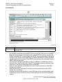
Finishing off:
Index
1
•
•
•
•
•
Screen element
Execute procedure for finishing off the measures plan and confirm by
clicking "OK"
If an ICOM is connected to the MOST direct access port, disconnect the MOST
direct access port when requested to do so by the ISTA/P system, remove the
ICOM from the MOST ring and close the MOST ring with the original flash plug
(bridge) in the vehicle. Fault codes may be entered and MOST control modules
may be registered incorrectly if the ICOM is not correctly disconnected from the
MOST direct access port.
Perform the finishing off procedures such as calibration, initialization, service
functions etc. in the vehicle test in the ISTA workshop system as defined in the
final report. Confirm the finishing off jobs individually.
Enter the time and date information to ensure correct calculation of the CBS
values in the vehicle.
After programming, reinstall all removed or disconnected data media (DVD,
iPod®, etc.) and check.
Compare the previously printed or noted CBS data of the control modules and,
if necessary, reset and correct as part of the vehicle test in the ISTA workshop
system.
Copyright © BMW AG/ISTA/P - User Documentation
Version V2.31.0/August 08
www.bmwicom.net
ISTA/P - User Documentation
Vehicle Programming in Service Applications
•
•
•
•
Page 15
of 131
Perform vehicle test with the ISTA workshop system and end vehicle test on
completion.
Park vehicle for at least 5 minutes (BN2000 and BN2020 vehicles) or 16 minutes
(I-bus vehicle) with terminal R OFF so that all control modules can assume sleep
mode, i.e. assume the rest state.
Note: control modules that do not assume sleep mode (rest state) can cause
closed-circuit current faults!
Make sure that the vehicle is OK.
Check all noted radio and TV frequencies as well as navigation destinations and
store manually if necessary.
Copyright © BMW AG/ISTA/P - User Documentation
Version V2.31.0/August 08
www.bmwicom.net
ISTA/P - User Documentation
Vehicle Programming in Service Applications
Page 16
of 131
Starting an ISTA/P session
Index Screen element
1
ISTA/P button
3
Workshop System Management
(WSM) button
Index Screen element
2
Callback Assistant button
Start ISTA/P from the ISSS jumpgate by selecting "Programming, Coding,
Individualization".
A maximum of three vehicles or one model series F01/F02 vehicle can be programmed
and encoded with ISTA/P on an ISSS.
Copyright © BMW AG/ISTA/P - User Documentation
Version V2.31.0/August 08
www.bmwicom.net
ISTA/P - User Documentation
Vehicle Programming in Service Applications
Page 17
of 131
Note:
The basic requirement for efficient programming is that the vehicle is correctly
prepared. When programming and coding, refer to the documentation "Preparing
vehicle programming and finishing off".
Callback Assistant
The Callback function in the workshop system management of the ISIS is to be used if
problems relating to the infrastructure of the IT system occur (e.g. ICOM connection not
possible) in the applications or during programming. The Callback function is a userprompted callback form. You will find a detailed description with instructions in the WSM
User Guide.
Index Screen element
1
Callback Assistant button
Index
2
Screen element
"New callback" button,
for creating a new case
Copyright © BMW AG/ISTA/P - User Documentation
Version V2.31.0/August 08
www.bmwicom.net
ISTA/P - User Documentation
Vehicle Programming in Service Applications
Page 18
of 131
Procedure if programming is terminated
Follow the instructions given in the programming system if the programming or coding
procedure is terminated during a programming session.
Contact Technical Support if the disruption in programming and coding relate to the
vehicle and cannot be solved in the workshop.
Copyright © BMW AG/ISTA/P - User Documentation
Version V2.31.0/August 08
www.bmwicom.net
ISTA/P - User Documentation
Vehicle Programming in Service Applications
Page 19
of 131
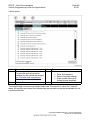
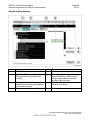
Menu bar and voltage display
Functions and actions can be selected directly in the menu bar. The voltage of the
connected vehicle is displayed below the menu bar:
Index Screen element
Index Screen element
1
Change to "Session" menu
2
Change to "Administration" menu
(ISTA/P start screen)
3
Change to "Connection manager" 4
Battery charge status is shown in
percent
(only ISID)
5
Print
6
Help function for ISTA/P
7
Minimize application
8
Close application
9
Terminal 30 in volts
10
Terminal 15 in volts
Copyright © BMW AG/ISTA/P - User Documentation
Version V2.31.0/August 08
www.bmwicom.net
ISTA/P - User Documentation
Vehicle Programming in Service Applications
Page 20
of 131
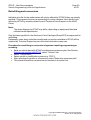
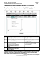
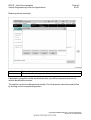
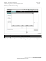
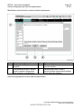
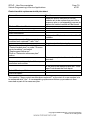
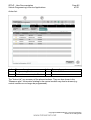
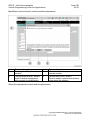
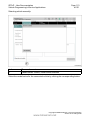
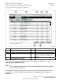
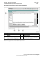
Sorting selection list
Index
1
Screen element
Column headings, showing "Data management" menu as an example
The selection list can be sorted in ascending or descending order by clicking on a
heading of a column that can be sorted.
Sorting is indicated by a white triangle pointing up or down. Columns that can be sorted
are: e.g. "Session name", "Start time", "Server" or "VIN".
Copyright © BMW AG/ISTA/P - User Documentation
Version V2.31.0/August 08
www.bmwicom.net
ISTA/P - User Documentation
Vehicle Programming in Service Applications
Page 21
of 131
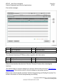
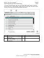
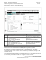
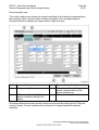
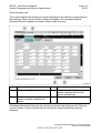
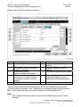
New session (ISTA/P start screen)
Index Screen element
1
"Session" menu
3
"Create new session" tab
Index Screen element
2
"Session overview" tab
All sessions that are currently running are shown in the session overview of the ISTA/P
start screen. The session overview can be selected at any time by clicking on the
"Session" menu button. Existing sessions can be adopted selecting from the session
overview and clicking on the "Continue" button.
A new program session is started via the "Create new session" tab.
Copyright © BMW AG/ISTA/P - User Documentation
Version V2.31.0/August 08
www.bmwicom.net
ISTA/P - User Documentation
Vehicle Programming in Service Applications
Page 22
of 131
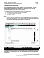
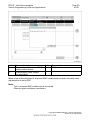
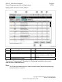
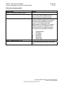
Selecting programming system (ISSS) automatically/manually:
Index Screen element
1
Select ISSS automatically
3
Index Screen element
2
"Continue" button
confirms selection
Select ISSS manually
If "Select ISSS automatically" is selected, the programming system (ISSS) with the
lowest number of current programming sessions is selected automatically. If there are
several programming systems with the same number of programming sessions, any
programming system is selected automatically.
The programming system must be selected manually if "Select ISSS manually" is
selected.
Copyright © BMW AG/ISTA/P - User Documentation
Version V2.31.0/August 08
www.bmwicom.net
ISTA/P - User Documentation
Vehicle Programming in Service Applications
Page 23
of 131
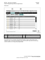
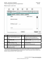
Selecting programming system (manual session selection):
Index Screen element
1
Display of detected programming
systems (ISSS)
3
"Continue" button
Index Screen element
2
Status of programming system
4
Update
Renewed check of connected
programming systems
The detected programming systems (ISSS) are shown together with their status.
Color Status
Green ISSS available
Color Status
Red
ISSS blocked
Yellow ISSS running at full capacity
Gray
No connection to ISSS
Select an available programming system and confirm by clicking on the "Continue"
button.
Copyright © BMW AG/ISTA/P - User Documentation
Version V2.31.0/August 08
www.bmwicom.net
ISTA/P - User Documentation
Vehicle Programming in Service Applications
Page 24
of 131
Connection manager:
Index Screen element
1
Type of interface
3
Index Screen element
2
Interface status
"Connect" button
The detected interfaces (ICOM) are shown together with their status.
Color Status
Green Interface free
Color Status
Red
Interface cannot be used
Yellow Interface connected
Select a free interface from the list. Click the "Connect" button after selecting the
interface.
The vehicle order or central coding key is read out. Refer to the document "ISTA/P Data
Management" if the vehicle order or central coding key cannot be read out.
Refer to the vehicle-specific sections "Vehicle Programming and Coding Procedure" for
further information on vehicle programming and coding.
Copyright © BMW AG/ISTA/P - User Documentation
Version V2.31.0/August 08
www.bmwicom.net
ISTA/P - User Documentation
Vehicle Programming in Service Applications
Page 25
of 131
Retrofitting and conversions
Individual retrofits for the model series will only be offered by ISTA/P if they are actually
possible. This prevents incorrect programming of control modules. If the retrofit is not
offered by ISTA/P by mistake, please consult Technical Parts Support via the ASAP
Portal.
Note:
The items displayed in ISTA/P may differ, depending on equipment fitted and
national market specification.
Only the items specified in the Electronic Parts Catalogue (Group EPC) are approved for
retrofitting.
Explanatory notes about individual retrofits and conversions available in ISTA/P will be
supplied by Technical Support as part of the fault elimination measures.
Procedure for retrofitting or conversion of systems requiring programming or
encoding:
•
•
•
•
•
Read out vehicle data with ISTA/P and determine measures plan. See Section:
Starting new session with ISTA/P, select "Vehicle" tab.
Select "Conversions".
Select retrofit or modification system (e.g. "PDC").
After selecting all retrofits or conversions, select "Determine measures plan".
The selected retrofits or conversions are itemized in the action list.
Copyright © BMW AG/ISTA/P - User Documentation
Version V2.31.0/August 08
www.bmwicom.net
ISTA/P - User Documentation
Vehicle Programming in Service Applications
Page 26
of 131
Vehicle menu:
Index Screen element
Index Screen element
1
"Conversions" tab:
2
"Vehicle actions" tab:
The retrofits and conversions
• Clear fault memory
available for the vehicle are shown,
• Select complete coding
see "Retrofits and conversions"
• Start system time of all
airbag control modules.
3
"Vehicle" menu
The retrofits and conversions are listed under the "Conversions" tab in the "Vehicle"
menu. All retrofits are shown first, followed by the possible conversions available for the
connected vehicle.
Copyright © BMW AG/ISTA/P - User Documentation
Version V2.31.0/August 08
www.bmwicom.net
ISTA/P - User Documentation
Vehicle Programming in Service Applications
Page 27
of 131
Procedure for IBAC enable codes
Some retrofits and conversions require the entry of IBAC enable codes. The IBAC
enable code can be obtained from the respective subsidiaries (VG) or from the
corresponding regional office and is valid for 30 days.
The following data are necessary to generate the IBAC enable code:
• IBAC order code (or selected retrofit or conversion)
• 7-digit vehicle identification number
• Your dealer number.
Note:
An up-to-date list of all IBAC order codes can be obtained from your subsidiary
(VG) or your regional office. This provides you with the opportunity of ordering the
required IBAC enable codes before working on the vehicle.
Index Screen element
1
"IBAC enable code" input box
Index Screen element
2
"OK" button
To enable the selected retrofit or conversion, enter the 15-character IBAC enable code
in the input box and confirm with "OK". The entry must take into account upper/lower
case letters.
Copyright © BMW AG/ISTA/P - User Documentation
Version V2.31.0/August 08
www.bmwicom.net
ISTA/P - User Documentation
Vehicle Programming in Service Applications
Page 28
of 131
E31, E32 and E34
Retrofit
Procedure for retrofitting systems requiring programming or coding in the model series
E31, E32, E34:
•
•
•
•
•
•
Read out vehicle data with ISTA/P.
See Section: Starting new session with ISTA/P
Select "Coding ZCS/FA"
Select model series (e.g. "E34")
Select "2 - Retrofit"
Select system (e.g. "1 - Air conditioning system (IHKR II/III)")
Start automatic encoding (confirm with "Y")
Follow the instructions given by the user prompts.
Conversion
Procedure for conversion of systems relevant to programming or encoding:
•
•
•
•
•
•
•
Read out vehicle data with ISTA/P.
See Section: Starting new session with ISTA/P
Select "Coding ZCS/FA"
Select model series (e.g. "E34")
Select "4 - Conversion".
Select system (e.g. "1 - Antitheft alarm system")
Select function (e.g. "2 - Visual alarm with hazard warning lights")
Start automatic encoding (confirm with "Y")
Follow the instructions given by the user prompts.
Note:
The central encoding key is not changed during the conversion procedure (see
footnotes for exceptions) so that the corresponding control module is recoded to
the basic status when newly encoded.
Calculating 5-character IBAC enable code
The 15-character IBAC enable code must be converted into a 5-character IBAC enable
code on vehicle model series that are processed via SGC (E31, E32, E34).
Copyright © BMW AG/ISTA/P - User Documentation
Version V2.31.0/August 08
www.bmwicom.net
ISTA/P - User Documentation
Vehicle Programming in Service Applications
Page 29
of 131
To convert the IBAC enable code, click on "Convert IBAC code" button in any SGC
screen. Enter the 15-character IBAC enable code and click on the "Calculate" button.
The entry must take into account upper/lower case letters.
Index Screen element
1
Input box for 15-character IBAC
enable code
3
"Calculate" button,
the 5-character IBAC enable code
is calculated
Index Screen element
2
Selected IBAC service
Copyright © BMW AG/ISTA/P - User Documentation
Version V2.31.0/August 08
www.bmwicom.net
ISTA/P - User Documentation
Vehicle Programming in Service Applications
Index Screen element
1
The calculated 5-character IBAC
enable code is shown
3
"Convert IBAC code" button
(not selectable)
Page 30
of 131
Index Screen element
2
"OK" button
Make a note of the calculated 5-character IBAC enable code and enter manually when
requested to do so by SGC.
Note:
The 5-character IBAC enable code is not stored.
Observe upper case/lower case letters.
Copyright © BMW AG/ISTA/P - User Documentation
Version V2.31.0/August 08
www.bmwicom.net
ISTA/P - User Documentation
Vehicle Programming in Service Applications
Page 31
of 131
Vehicle and Key Memory (CKM)
On customer request, various vehicle settings can be changed by means of coding on
certain E-model series (e.g. E46, E6X). Some settings (Key) are allocated to a certain key
(max. four keys), e.g. heating/air conditioning/ventilation while other settings (Vehicle)
apply globally to the entire vehicle, e.g. antitheft alarm system.
Vehicle and Key Memory settings can be selected under the "CKM" tab after
determining the native measures plan in the "Vehicle" menu.
Note:
Due to different legal stipulations, there may be national differences in possible
CKM settings. Factory settings may also vary from country to country.
Note:
When replacing control modules, it may happen that individual data in the CKM
settings are not automatically restored. Before replacing a control module, the
CKM settings in the vehicle must be printed out so that these can be restored
after the control module has been replaced.
BMW E70, E71, E81, E82, E87, E88, E90, E91 E92, E93, F01 F02
MINI R55 and R56
On these model series, all Vehicle and Key Memory functions are programmed directly
in the vehicle (please refer to "Personal Profile" in the Owner's Manual: individual
settings for a maximum of 3 remote control units via the display in the instrument cluster
or via the Central Information Display).
BMW E38, E39, E46, E52, E53, E60, E61, E63, E64, E65, E66, E83, E85 and E86
MINI R50, R52 and R53
Rolls-Royce
The procedure for programming the Vehicle and Key Memory is described below. The
basic prerequisite is that all control modules on a vehicle are programmed to the current
software status:
Two or more parameter keywords (e.g. active, inactive) are assigned to a function or a
function keyword. The current setting is shown by a selected checkbox next to the
parameter keyword and can be changed by the service technician. Key functions can be
set individually for the max. 4 keys. The factory setting is represented by a
corresponding symbol next to the parameter keyword.
The CKM functions are divided into a maximum of three levels of hierarchy. Main group
(e.g. central locking), group (e.g. unlocking rear window, boot/rear lid) and an optional
subgroup (e.g. lids after ignition on).
Copyright © BMW AG/ISTA/P - User Documentation
Version V2.31.0/August 08
www.bmwicom.net
ISTA/P - User Documentation
Vehicle Programming in Service Applications
Page 32
of 131
Vehicle and Key Memory
Index Screen element
1
"CKM" tab
3
Symbol for "Factory settings",
shows the factory setting of the
function
5
7
Index Screen element
2
"Vehicle" menu
4
Tick - the green tick shows the
selected setting of the function,
the gray tick shows the active
setting of the function
"Factory settings" button,
6
"Cancel all" button,
establishes the factory settings for
cancels all settings
the vehicle and keys
"Determine measures plan" button
Copyright © BMW AG/ISTA/P - User Documentation
Version V2.31.0/August 08
www.bmwicom.net
ISTA/P - User Documentation
Vehicle Programming in Service Applications
Page 33
of 131
Note:
You can print out the set CKM values. Printing out the CKM settings could cause
values that have been entered in the list but not yet stored in the vehicle to be lost,
making it necessary to re-enter them. It is advisable to print out the CKM settings
at the start of programming and if necessary immediately after completing CKM
reprogramming.
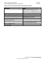
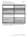
Procedure for changing CKM settings
User action
Result
Activate the required change by selecting
"active", "not active" or one of the specified
settings.
Click on "Determine measures plan" button.
Measures plan is determined.
Click on "Accept measures plan" button.
The data is saved to the vehicle.
Select "Final report" tab.
A final report of the settings that have
been performed is shown.
Note:
The selected settings for the Vehicle and Key Memory are retained even when the
control modules are reprogrammed or encoded. If the CKM backup or restore
cannot be successfully performed, this will be seen in the final report.
Copyright © BMW AG/ISTA/P - User Documentation
Version V2.31.0/August 08
www.bmwicom.net
ISTA/P - User Documentation
Vehicle Programming in Service Applications
Page 34
of 131
ISTA/P Data management
Enable codes and vehicle orders or central coding keys are imported and managed via
the "Data management" menu button. This button is also used to show the reports of
previous sessions.
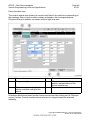
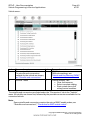
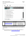
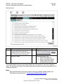
Data management:
Index Screen element
1
"Import Enable code" tab
3
5
"Import vehicle order" tab
"Delete vehicle order" tab,
deletes imported vehicle orders
Index Screen element
2
"Delete enable code" tab,
deletes imported enable codes
4
"Data management" menu
6
"Reports" tab,
shows previous sessions with final
report
Copyright © BMW AG/ISTA/P - User Documentation
Version V2.31.0/August 08
www.bmwicom.net
ISTA/P - User Documentation
Vehicle Programming in Service Applications
Page 35
of 131
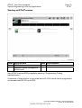
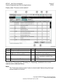
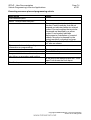
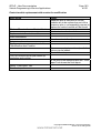
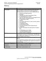
Import vehicle order
All the vehicle identification numbers where the vehicle order is in the data stock of
ISTA/P are shown in a selection list. The user can select a vehicle identification number
and have the corresponding vehicle order displayed. The user can additionally search for
a vehicle identification number by correspondingly changing the sorting function. New
vehicle orders can be imported from removable data media to the data stock of ISTA/P.
User action
Select "Import vehicle order" tab.
Result
Vehicle identification numbers are shown,
for which vehicle orders or central coding
keys are already available.
Click on "Import" button.
Request to insert a data medium is shown.
Load data medium in ISSS or set up
connection between ISSS and USB
storage medium.
Click on "OK" button.
Vehicle order is imported.
Note:
In view of the variety of USB storage media available on the market, a functional
guarantee cannot be given under ISTA/P for all USB storage media used on an
ISSS.
Copyright © BMW AG/ISTA/P - User Documentation
Version V2.31.0/August 08
www.bmwicom.net
ISTA/P - User Documentation
Vehicle Programming in Service Applications
Page 36
of 131
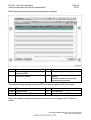
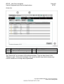
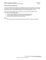
Import activation code
In some control modules the software is enabled with ISTA/P (e.g. when programming
the CCC, an enable code must be imported in order to activate the "Expanded Voice
Recognition" option).
In ISTA/P it is possible to import enable codes for a vehicle before working through the
measures plan. All imported enable codes are stored within the ISPI network and are
available for future programming sessions without the need to import them again.
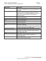
User action
Select "Import enable code" tab.
Result
Vehicle identification numbers are shown,
for which enable codes are already
available.
Click on "Import" button.
Request to insert a data medium is shown.
Load data medium in ISSS or set up
connection between ISSS and USB
storage medium.
Click on "OK" button.
Enable code is imported.
Note:
With the vehicle identification number, the enable code can be ordered and
downloaded as a ZIP files (containing 3 files) through the ASAP-Portal.
The ZIP file must be unzipped and placed on the "Root directory" of the data
medium (e.g. F:\). In view of the variety of USB storage media available on the
market, a functional guarantee cannot be given under ISTA/P for all USB storage
media used on an ISSS.
Copyright © BMW AG/ISTA/P - User Documentation
Version V2.31.0/August 08
www.bmwicom.net
ISTA/P - User Documentation
Vehicle Programming in Service Applications
Page 37
of 131
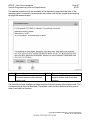
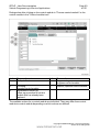
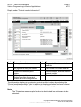
If a required enable code is not available in the workshop network at the start of the
measures plan, a request to import/order the enable code will be issued while working
through the measures plan.
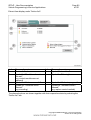
Index Screen element
1
"Continue" button
Continue measures plan without
enable code
Index Screen element
2
"Start import" button,
imports enable code from data
medium
It is possible to work through the measures plan without importing the enable code. The
corresponding is then not available. The enable code can be entered at a later point in
time to activate the function.
Copyright © BMW AG/ISTA/P - User Documentation
Version V2.31.0/August 08
www.bmwicom.net
ISTA/P - User Documentation
Vehicle Programming in Service Applications
Page 38
of 131
BMW vehicle programming and encoding
Depending on the structure of the vehicle system network, the model series can be
grouped together in model series groups with respect to the ISTA/P programming
routine: The following pages contain descriptions of the programming procedure.
Note:
The basic requirement for efficient programming is that the vehicle is correctly
prepared. Please refer to the description "Vehicle programming and finishing off".
Copyright © BMW AG/ISTA/P - User Documentation
Version V2.31.0/August 08
www.bmwicom.net
ISTA/P - User Documentation
Vehicle Programming in Service Applications
Page 39
of 131
Programming procedure for model series E31, E32 and E34
The application software "Control module encoding" (SGC) for encoding and
programming the earlier model series has been integrated into ISTA/P.
Index Screen element
1
"Vehicle Memory" tab,
Vehicle Memory value settings
3
"Vehicle coding" tab,
control module coding
5
7
"Control module programming"
tab, service measures
Replacing control modules or
EPROM, deleting adaptation
values
"EWS/DDE calibration" tab,
synchronizes EWS and DME
control modules
Index Screen element
2
"Key Memory" tab,
Key Memory value settings
4
"Service functions" tab,
shows service functions,
(e.g. flash radio)
6
"EWS/DME calibration" tab,
synchronizes EWS and DME
control modules
A detailed description of the programming and encoding procedure is not provided here
as only the access and not the procedure has changed in terms of programming the
model series that are programmed via SCG programming.
Copyright © BMW AG/ISTA/P - User Documentation
Version V2.31.0/August 08
www.bmwicom.net
ISTA/P - User Documentation
Vehicle Programming in Service Applications
Page 40
of 131
Programming abort of programmable drive control modules (E31, E32, E34)
Proceed as follows if programming always cancels at the same point:
•
•
•
•
•
Disconnect the drive control module for about 1 minute
Reconnect the drive control module
Switch on ignition
Repeat programming
Switch off ignition.
Programming caused by the instrument cluster (E31, E32, E34)
In isolated cases, the instrument cluster can interrupt communication on the diagnosis
lead during programming. In such cases, repeat programming with the instrument
cluster disconnected. Before EWS calibration, the instrument cluster must be
reconnected.
Malfunctions on the diagnosis cable (E31, E32, E34)
With the following engine control module, it may be the case that no programming can
be performed again after a programming abort:
•
•
ME7.2, M5.2, M5.2.1 in M62 engine
M5.2.1 in M73 engine.
After trying again, the fault message:
"Programming cannot be performed without errors - repeat programming" appears.
Diagnosis is not possible here. Switch the ignition off and back on again. You can now
repeat programming.
Display of error messages (E31, E32, E34)
The text display of fault messages appears on the screen. The relevant fault code can be
called up by pressing the information button at the bottom right of the screen.
Copyright © BMW AG/ISTA/P - User Documentation
Version V2.31.0/August 08
www.bmwicom.net
ISTA/P - User Documentation
Vehicle Programming in Service Applications
Page 41
of 131
Contact Technical Support
Consult Technical Support if
•
•
Programming aborts repeatedly occur
Programming is not possible.
In such cases, keep the following ready to hand:
•
•
•
•
•
Measures plan
Final report
Diagnosis printout of the control modules concerned
Full error message
Version of ISTA/P used.
New coding (E31, E32, E34)
All control modules that require encoding MUST be encoded after being fitted.
Malfunctions could occur if this encoding procedure is not carried out after fitting.
Encoding a control module takes no more than 30 seconds.
Proceed as follows:
•
•
•
•
•
•
•
•
Connect the BMW programming system to the vehicle
Switch on ignition
Select model series in ISTA/P
Select "Encoding ZCS/FA"
Select model series
Select "1 - New coding"
Select system (e.g. "Airbag")
Answer the question "Start automatic encoding" with "Y".
Note:
Encoding cannot be interrupted once the user has confirmed automatic encoding
with "Y".
•
•
Follow the instructions given by the user prompts
After encoding, clear the fault memory via the vehicle test in the ISTA
workshop system.
Copyright © BMW AG/ISTA/P - User Documentation
Version V2.31.0/August 08
www.bmwicom.net
ISTA/P - User Documentation
Vehicle Programming in Service Applications
Page 42
of 131
Programming procedure for the model series E36, E38, E39, E46, E52,
E53, E60, E61, E63, E64, E65, E66, E70, E71, E81, E82, E83, E85, E86,
E87, E88, E90, E91, E92 and E93
The following pages contain descriptions of the programming procedure for the BMW
model series listed above.
Note:
The basic requirement for efficient programming is that the vehicle is correctly
prepared. Please refer to the description "Vehicle programming and finishing off".
Read out vehicle data with ISTA/P. See Section: Start new session with ISTA/P.
The measures plan can be expanded by the following actions:
•
•
•
Carry out conversion
Carry out vehicle actions
Set CKM values (E36, E38, E39, E46, E52, E53, E60, E61, E63, E64, E65 E66,
E83, E85 and E86)
− Select "Vehicle" tab.
− Select "CKM" tab.
− Print CKM values.
• Prepare for control module replacement
• Programs control module
• Encode control module.
The actions can be selected as follows:
•
•
Under the "Process control modules" tab by directly selecting the actions or
clicking on the control module
Under the "Control module tree" tab by clicking on the control module.
Copyright © BMW AG/ISTA/P - User Documentation
Version V2.31.0/August 08
www.bmwicom.net
ISTA/P - User Documentation
Vehicle Programming in Service Applications
Page 43
of 131
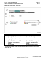
Connection to vehicle is set up automatically:
Index Screen element
1
"Programming" menu
3
5
7
Index Screen element
2
I-stage (actual),
shows current I-stage of vehicle
4
Progress bar,
shows processing progress
Enable code status,
status of enable code used or
required in vehicle
Last processed with,
6
shows the Progman or ISTA/P
version, with which the vehicle was
last processed
"Vehicle details" tab
I-stage (factory),
shows the I-stage with which the
vehicle was produced
Follow and confirm the instructions provided by the programming system.
By reading out the vehicle details it is possible to determine whether the vehicle
corresponds to the current software status. Unnecessary vehicle programming can be
avoided in this way.
The native measures plan is determined after the connection to the vehicle has been set
up successfully. This is shown under the "Programming" menu button.
Copyright © BMW AG/ISTA/P - User Documentation
Version V2.31.0/August 08
www.bmwicom.net
ISTA/P - User Documentation
Vehicle Programming in Service Applications
Page 44
of 131
Selecting vehicle manually:
Index
1
Screen element
"Product line" button, product line selection
If automatic recognition of the model series fails, you will be requested to enter the
vehicle identification number.
The vehicle can also be determined manually. For this purpose, select the product line
by clicking on the corresponding button.
Copyright © BMW AG/ISTA/P - User Documentation
Version V2.31.0/August 08
www.bmwicom.net
ISTA/P - User Documentation
Vehicle Programming in Service Applications
Page 45
of 131
Selecting model series manually:
Index
1
Screen element
"Model series" button, model series selection
Select the model series for the connected vehicle by clicking the corresponding button.
Copyright © BMW AG/ISTA/P - User Documentation
Version V2.31.0/August 08
www.bmwicom.net
ISTA/P - User Documentation
Vehicle Programming in Service Applications
Page 46
of 131
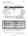
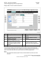
Control module tree:
The control module tree shows the control units fitted in the vehicle corresponding to
the topology. Each control module is shown as linked to the corresponding bus.
Compound control modules are shown within a light blue area.
Index Screen element
1
"Programming" menu
3
"Select complete coding" button,
selects complete coding of the
vehicle
Index Screen element
2
"Control module tree" tab,
graphic representation of the
control module tree
4
"Remove actions" button
All actions determined based on the context are removed by clicking on the "Remove
actions" button. Control module actions relevant to I-stages cannot be selected
manually.
Copyright © BMW AG/ISTA/P - User Documentation
Version V2.31.0/August 08
www.bmwicom.net
ISTA/P - User Documentation
Vehicle Programming in Service Applications
Page 47
of 131
Display under "Process control module":
Index Screen element
1
"Programming" menu
3
Programming,
programs control module
5
Replacement
7
Index Screen element
2
"Process control modules" tab
4
Encoding,
encodes control module
6
"Select complete coding" button,
selects complete coding of the
vehicle
"Remove actions" button
The actions ("Programming", "Encoding" or "Replacing") available for the control
modules can be selected directly.
Note:
The "Determine measures plan" button is deactivated if determining the target
context results in no action.
Copyright © BMW AG/ISTA/P - User Documentation
Version V2.31.0/August 08
www.bmwicom.net
ISTA/P - User Documentation
Vehicle Programming in Service Applications
Page 48
of 131
Action list:
Index Screen element
Index Screen element
1
"Programming" menu
2
"Action list" tab
3
"Determine measures plan" button
The "Action list" is a summary of the planned actions. They are also shown in the
"Measures plan". Information relating to the control module may also be shown (e.g.
control module can no longer be programmed).
Copyright © BMW AG/ISTA/P - User Documentation
Version V2.31.0/August 08
www.bmwicom.net
ISTA/P - User Documentation
Vehicle Programming in Service Applications
Page 49
of 131
Vehicle menu:
Index Screen element
Index Screen element
1
"Conversions" tab:
2
"CKM" tab
The retrofits and conversions
CKM value settings, see
available for the vehicle are shown,
"Vehicle and Key Memory (CKM)"
see "Retrofits and conversions"
3
"Vehicle" menu
4
"Vehicle actions" tab:
• Clear fault memory
• Select complete coding
• Start system time of all
airbag control modules.
The retrofits and conversions are listed under the "Conversions" tab in the "Vehicle"
menu. All retrofits are shown first, followed by the possible conversions available for the
connected vehicle.
Note:
Some retrofits and conversions require the entry of IBAC enable codes, see
"Retrofits and conversions", "Procedure for IBAC enable codes".
Copyright © BMW AG/ISTA/P - User Documentation
Version V2.31.0/August 08
www.bmwicom.net
ISTA/P - User Documentation
Vehicle Programming in Service Applications
Page 50
of 131
Dialogue box after clicking on the control module in "Process control module" or the
control module in the "Control module tree":
Index Screen element
1
"Edit plan" tab
3
5
Encoding,
encodes control module
Replacement follow-up,
follow-up procedure for control
module that has already been
replaced
Index Screen element
2
Programming,
programs control module
4
Replace, replaces control module
The available actions for a control module are individual. They may differ from control
module to control module depending on which actions are defined.
Copyright © BMW AG/ISTA/P - User Documentation
Version V2.31.0/August 08
www.bmwicom.net
ISTA/P - User Documentation
Vehicle Programming in Service Applications
Page 51
of 131
Extract from display under "Action list":
Index Screen element
1
"Action list" tab
3
Symbol for "Conditions for action
not met"
(e.g. control module was not
replaced)
5
Symbol for "Action successful"
Index Screen element
2
Symbol "Action failed"
4
Symbol for "Warning"
6
Symbol for "Action in progress"
7
8
Symbol for "Hardware action
planned"
(e.g. replace control module)
Symbol for "Software action
planned"
(e.g. encoding)
The planned actions are shown together with their respective status by selecting the
"Action list" tab.
Copyright © BMW AG/ISTA/P - User Documentation
Version V2.31.0/August 08
www.bmwicom.net
ISTA/P - User Documentation
Vehicle Programming in Service Applications
Page 52
of 131
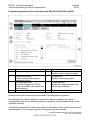
Display under "Control module information":
Index Screen element
1
Status, planned action
3
5
7
9
Bus system to which the control
module is connected
Programming status,
display of detailed information
Assembly number,
is made up of hardware number
and software number of control
module
Control module variant
Index Screen element
2
Diagnosis address of control
module
4
Hardware number of control
module
6
"Determine measures plan" button
8
Still programmable,
shows how often the control
module can still be programmed
The information relating to the selected control module is shown by selecting the
"Control module information" tab. In addition to the planned action and other relevant
data, it also shows how often the control module can still be programmed.
Note:
The "Determine measures plan" button is deactivated if no actions are to be
selected.
Copyright © BMW AG/ISTA/P - User Documentation
Version V2.31.0/August 08
www.bmwicom.net
ISTA/P - User Documentation
Vehicle Programming in Service Applications
Page 53
of 131
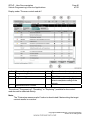
Determine measures plan
User action
Select "Determine measures plan".
Result
The "Measures plan", "Control module
tree", "Action list", "Order list" and
"Enable code list" tabs are shown.
The measures plan is shown in the menu
window. Control modules that are to be
processed are identified by a yellow
symbol. A red symbol indicates
replacement or installation of a control
module. No action is planned for the
control module if no symbol is shown.
The actions are indicated as follows:
P
C
I
M
R
U
Programming
Encoding
Initializing
Installing
Replacing
Removing.
Select "Measures plan" tab.
The measures plan is shown in the print
view.
Copyright © BMW AG/ISTA/P - User Documentation
Version V2.31.0/August 08
www.bmwicom.net
ISTA/P - User Documentation
Vehicle Programming in Service Applications
Page 54
of 131
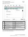
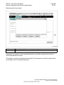
Measures plan in print view:
Index Screen element
1
"Measures plan" tab,
shows measures plan in print
view
3
"Action list" tab,
shows the planned actions in a
table
5
"Enable code list" tab,
shows the enable codes used
7
"Accept measures plan" tab,
executes measures plan and
programs vehicle
Index Screen element
2
"Control module tree" tab,
shows the control module tree
together with the planned actions
4
"Order list" tab,
shows control modules to be ordered
6
"Print" button,
prints the measures plan
The measures plan contains actions that need to be carried out in order to eliminate a
vehicle fault. In addition to the determined actions, it also shows the vehicle details, the
session name and the ISTA/P version used.
Copyright © BMW AG/ISTA/P - User Documentation
Version V2.31.0/August 08
www.bmwicom.net
ISTA/P - User Documentation
Vehicle Programming in Service Applications
Page 55
of 131
Executing measures plan and programming vehicle
User action
Result
Print measures plan.
Select "Accept measures plan".
The measures plan is shown in the menu
window. Control modules that did not
respond are indicated without a colored
symbol. Control modules that are to be
processed are identified by a yellow
symbol. A red symbol indicates
replacement or installation of a control
module. No action is planned for the
control module if no symbol is shown.
The "Control module tree" and "Action
list" tabs are shown.
Observe and acknowledge safety
information on programming.
Measures plan is executed.
Plan is followed up.
Carry out initialization and instructions of
plan follow-up procedure and confirm.
At the end of the measures plan the "Final
report" tab shows the final report.
Print final report.
Copyright © BMW AG/ISTA/P - User Documentation
Version V2.31.0/August 08
www.bmwicom.net
ISTA/P - User Documentation
Vehicle Programming in Service Applications
Page 56
of 131
Control module replacement
The control modules to be replaced are determined by the measures plan. The request
to replace a control unit is integrated in the measures plan procedure. The new control
modules must be encoded after installation to ensure they operate correctly.
The control module replacement procedure can be carried out as follows and is
described on the following pages:
•
•
•
Control module replacement without interrupting the session
Control module replacement with session for modification
Control module replacement with plan abort.
Note:
When replacing, refer to the technical documentation for the control module.
Copyright © BMW AG/ISTA/P - User Documentation
Version V2.31.0/August 08
www.bmwicom.net
ISTA/P - User Documentation
Vehicle Programming in Service Applications
Page 57
of 131
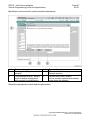
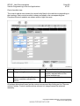
Modification instructions for control module replacement:
Index Screen element
1
Confirmation "Replace control
module"
3
"Modification session" button,
control module replacement
with session for modification
Index Screen element
2
"Plan abort" button
Cancels session
4
"Modification done" button,
control module replacement without
interrupting the session
Select the appropriate control module replacement.
Copyright © BMW AG/ISTA/P - User Documentation
Version V2.31.0/August 08
www.bmwicom.net
ISTA/P - User Documentation
Vehicle Programming in Service Applications
Page 58
of 131
Control module replacement without interrupting the session
User action
Result
Measures plan is executed. If control
modules are to be replaced as part of the
measures plan, a corresponding request to
replace the control module will be issued.
Replace or install control modules.
Confirm replacement request.
Click on "Modification done" button.
Measures plan is continued.
Plan is followed up.
Carry out instructions of plan follow-up
procedure and confirm.
At the end of the measures plan the "Final
report" tab shows the final report.
Select "Final report" tab.
Print final report.
Copyright © BMW AG/ISTA/P - User Documentation
Version V2.31.0/August 08
www.bmwicom.net
ISTA/P - User Documentation
Vehicle Programming in Service Applications
Page 59
of 131
Control module replacement with session for modification
User action
Result
Measures plan is executed. If control
modules are to be replaced as part of the
measures plan, a corresponding request to
replace the control module will be issued.
Click on "Session for modification" button.
Session is stored and ended
Replace or install control modules.
Start new session.
Stored session is found.
Select stored session.
Confirm replacement request and click on
"Modification done" button.
The measures plan is continued, no further
actions can be added.
Plan is followed up.
Carry out instructions of plan follow-up
procedure and confirm.
At the end of the measures plan the "Final
report" tab shows the final report.
Select "Final report" tab.
Print final report.
Copyright © BMW AG/ISTA/P - User Documentation
Version V2.31.0/August 08
www.bmwicom.net
ISTA/P - User Documentation
Vehicle Programming in Service Applications
Page 60
of 131
Control module replacement with plan abort
User action
Result
Measures plan is executed. If control
modules are to be replaced as part of the
measures plan, a corresponding request to
replace the control module will be issued.
Click on "Plan abort" button.
Session is terminated
Replace or install control modules.
Start new session.
Dialogue box "Replaced control modules"
is shown.
Answer the question "Have control
modules been replaced?" with "Yes".
Select replaced control modules in
"Control module tree" or under "Process
control modules" and select
"Replacement follow-up".
Click on "Determine measures plan"
button.
Target context is determined.
Further actions can be added.
The measures plan is determined and
executed.
Carry out instructions of plan follow-up
procedure and confirm.
At the end of the measures plan the "Final
report" tab shows the final report.
Select "Final report" tab.
Print final report.
The question "Have control modules been replaced?" at the start of a new session is to
be answered with "Yes". A corresponding replacement follow-up procedure is then
executed as part of the measures plan.
Copyright © BMW AG/ISTA/P - User Documentation
Version V2.31.0/August 08
www.bmwicom.net
ISTA/P - User Documentation
Vehicle Programming in Service Applications
Page 61
of 131
Programming procedure for model series F01 and F02
The following pages contain descriptions of the programming procedure for the BMW
model series F01 and F02.
Note:
The basic requirement for efficient programming is that the vehicle is correctly
prepared. Please refer to the description "Vehicle programming and finishing off".
Read out vehicle data with ISTA/P.
See Section: Start new session with ISTA/P.
The measures plan can be expanded by the following actions:
•
•
•
•
•
Carry out conversion
Carry out vehicle actions
Prepare for control module replacement
Programs control module
Encode control module.
The actions can be selected as follows:
•
•
Under the "Process control modules" tab by directly selecting the actions or
clicking on the control module
Under the "Control module tree" tab by clicking on the control module.
Copyright © BMW AG/ISTA/P - User Documentation
Version V2.31.0/August 08
www.bmwicom.net
ISTA/P - User Documentation
Vehicle Programming in Service Applications
Page 62
of 131
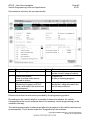
Connection to vehicle is set up automatically:
Index Screen element
1
"Programming" menu
3
5
7
Index Screen element
2
I-stage (actual),
shows current I-stage of vehicle
4
Progress bar,
shows processing progress
Enable code status,
status of enable code used or
required in vehicle
Last processed with,
6
sShows the Progman or ISTA/P
version, with which the vehicle was
last processed
"Vehicle details" tab
I-stage (factory),
shows the I-stage with which the
vehicle was produced
Follow and confirm the instructions provided by the programming system.
By reading out the vehicle details it is possible to determine whether the vehicle
corresponds to the current software status. Unnecessary vehicle programming can be
avoided in this way.
The native measures plan is determined after the connection to the vehicle has been set
up successfully. This is shown under the "Programming" menu button.
Copyright © BMW AG/ISTA/P - User Documentation
Version V2.31.0/August 08
www.bmwicom.net
ISTA/P - User Documentation
Vehicle Programming in Service Applications
Page 63
of 131
Selecting vehicle manually:
Index
1
Screen element
"Product line" button, product line selection
If automatic recognition of the model series fails, you will be requested to enter the
vehicle identification number.
The vehicle can also be determined manually. For this purpose, select the product line
by clicking on the corresponding button.
Copyright © BMW AG/ISTA/P - User Documentation
Version V2.31.0/August 08
www.bmwicom.net
ISTA/P - User Documentation
Vehicle Programming in Service Applications
Page 64
of 131
Selecting model series manually:
Index
1
Screen element
"Model series" button, model series selection
Select the model series for the connected vehicle by clicking the corresponding button.
Copyright © BMW AG/ISTA/P - User Documentation
Version V2.31.0/August 08
www.bmwicom.net
ISTA/P - User Documentation
Vehicle Programming in Service Applications
Page 65
of 131
Control module tree:
The control module tree shows the control units fitted in the vehicle corresponding to
the topology. Each control module is shown as linked to the corresponding bus.
Compound control modules are shown within a light blue area.
Index Screen element
1
"Programming" menu
3
"Select complete coding" button,
selects complete coding of the
vehicle
Index Screen element
2
"Control module tree" tab,
graphic representation of the
control module tree
4
"Remove actions" button
All actions determined based on the context are removed by clicking on the "Remove
actions" button. Control module actions relevant to I-stages cannot be selected
manually.
Copyright © BMW AG/ISTA/P - User Documentation
Version V2.31.0/August 08
www.bmwicom.net
ISTA/P - User Documentation
Vehicle Programming in Service Applications
Page 66
of 131
Display under "Process control module":
Index Screen element
1
"Programming" button
3
Programming
Index Screen element
2
"Process control modules" tab
4
Encoding
5
Replacement
6
7
"Remove actions" button
"Select complete coding" button,
selects complete coding of the
vehicle
The actions ("Programming", "Encoding" or "Replacing") available for the control
modules can be selected directly.
Note:
The "Determine measures plan" button is deactivated if determining the target
context results in no action.
Copyright © BMW AG/ISTA/P - User Documentation
Version V2.31.0/August 08
www.bmwicom.net
ISTA/P - User Documentation
Vehicle Programming in Service Applications
Page 67
of 131
Action list:
Index Screen element
Index Screen element
1
"Programming" button
2
"Action list" tab
3
"Determine measures plan" button
The "Action list" is a summary of the planned actions. They are also shown in the
"Measures plan". Information relating to the control module may also be shown (e.g.
control module can no longer be programmed).
Copyright © BMW AG/ISTA/P - User Documentation
Version V2.31.0/August 08
www.bmwicom.net
ISTA/P - User Documentation
Vehicle Programming in Service Applications
Page 68
of 131
Vehicle menu:
Index Screen element
1
"Conversions" tab:
Shows retrofits and conversions,
see Retrofits and conversions
3
Index Screen element
2
"Vehicle actions" tab:
• Clear fault memory
• Select complete coding
• Start system time of all
airbag control modules.
"Vehicle" menu
The retrofits and conversions are listed under the "Conversions" tab in the "Vehicle"
menu. All retrofits are shown first, followed by the possible conversions available for the
connected vehicle.
Note:
Some retrofits and conversions require the entry of IBAC enable codes, see
Retrofits and conversions, "Procedure for IBAC enable codes".
Copyright © BMW AG/ISTA/P - User Documentation
Version V2.31.0/August 08
www.bmwicom.net
ISTA/P - User Documentation
Vehicle Programming in Service Applications
Page 69
of 131
Dialogue box after clicking on the control module in "Process control module" or the
control module in the "Control module tree":
Index Screen element
1
"Edit plan" tab
3
5
Encoding,
encodes control module
Replacement follow-up,
follow-up procedure for control
module that has already been
replaced
Index Screen element
2
Programming,
programs control module
4
Replace, replaces control module
The available actions for a control module are individual. They may differ from control
module to control module depending on which actions are defined.
Copyright © BMW AG/ISTA/P - User Documentation
Version V2.31.0/August 08
www.bmwicom.net
ISTA/P - User Documentation
Vehicle Programming in Service Applications
Page 70
of 131
Extract from display under "Action list":
Index Screen element
1
"Action list" tab
3
Symbol for "Conditions for action
not met"
(e.g. control module was not
replaced)
5
Symbol for "Action successful"
Index Screen element
2
Symbol "Action failed"
4
Symbol for "Warning"
6
Symbol for "Action in progress"
7
8
Symbol for "Hardware action
planned"
(e.g. replace control module)
Symbol for "Software action
planned"
(e.g. encoding)
The planned actions are shown together with their respective status by selecting the
"Action list" tab.
Copyright © BMW AG/ISTA/P - User Documentation
Version V2.31.0/August 08
www.bmwicom.net
ISTA/P - User Documentation
Vehicle Programming in Service Applications
Page 71
of 131
Display under "Control module information":
Index Screen element
1
Status, planned action
3
5
7
Bus system to which the control
module is connected
"Determine measures plan"
button
Still programmable,
Shows how often the control
module can still be programmed
Index Screen element
2
Diagnosis address of control
module
4
Part number of control module
6
8
Technical units, software status in
control module
Control module variant
The information relating to the selected control module is shown by selecting the
"Control module information" tab. In addition to the planned action and other relevant
data, it also shows how often the control module can still be programmed.
Note:
The "Determine measures plan" button is deactivated if no actions are to be
selected.
Copyright © BMW AG/ISTA/P - User Documentation
Version V2.31.0/August 08
www.bmwicom.net
ISTA/P - User Documentation
Vehicle Programming in Service Applications
Page 72
of 131
Determine measures plan
User action
Select "Determine measures plan".
Result
The "Measures plan", "Control module
tree", "Action list", "Order list" and
"Enable code list" tabs are shown.
The measures plan is shown in the menu
window. Control modules that are to be
processed are identified by a yellow
symbol. A red symbol indicates
replacement or installation of a control
module. No action is planned for the
control module if no symbol is shown. The
actions are indicated as follows:
P
C
I
M
R
U
Programming
Encoding
Initializing
Installing
Replacing
Removing.
Select "Measures plan" tab.
The measures plan is shown in the print
view.
Copyright © BMW AG/ISTA/P - User Documentation
Version V2.31.0/August 08
www.bmwicom.net
ISTA/P - User Documentation
Vehicle Programming in Service Applications
Page 73
of 131
Measures plan in print view:
Index Screen element
1
"Measures plan" tab,
shows measures plan in print
view
3
"Action list" tab,
shows the planned actions in a
table
5
"Enable code list" tab,
shows the enable codes used
7
"Accept measures plan" tab,
executes measures plan and
programs vehicle
Index Screen element
2
"Control module tree" tab,
shows the control module tree
together with the planned actions
4
"Order list" tab,
shows control modules to be ordered
6
"Print" button,
prints the measures plan
The measures plan contains actions that need to be carried out in order to eliminate a
vehicle fault. In addition to the determined actions, it also shows the vehicle details, the
session name and the ISTA/P version used.
Copyright © BMW AG/ISTA/P - User Documentation
Version V2.31.0/August 08
www.bmwicom.net
ISTA/P - User Documentation
Vehicle Programming in Service Applications
Page 74
of 131
Executing measures plan and programming vehicle
User action
Result
Print measures plan.
Select "Accept measures plan".
The measures plan is shown in the menu
window. Control modules that did not
respond are indicated without a colored
symbol. Control modules that are to be
processed are identified by a yellow
symbol. A red symbol indicates
replacement or installation of a control
module. No action is planned for the
control module if no symbol is shown.
The "Control module tree" and "Action
list" tabs are shown.
Observe and acknowledge safety
information on programming.
Measures plan is executed.
Plan is followed up.
Carry out initialization and instructions of
plan follow-up procedure and confirm.
At the end of the measures plan the "Final
report" tab shows the final report.
Print final report.
Copyright © BMW AG/ISTA/P - User Documentation
Version V2.31.0/August 08
www.bmwicom.net
ISTA/P - User Documentation
Vehicle Programming in Service Applications
Page 75
of 131
Control module replacement
The control modules to be replaced are determined by the measures plan. The request
to replace a control unit is integrated in the measures plan procedure. The new control
modules must be encoded after installation to ensure they operate correctly.
The control module replacement procedure can be carried out as follows and is
described on the following pages:
•
•
•
Control module replacement without interrupting the session
Control module replacement with session for modification
Control module replacement with plan abort.
Note:
When replacing, refer to the technical documentation for the control module.
Copyright © BMW AG/ISTA/P - User Documentation
Version V2.31.0/August 08
www.bmwicom.net
ISTA/P - User Documentation
Vehicle Programming in Service Applications
Page 76
of 131
Modification instructions for control module replacement:
Index Screen element
1
Confirmation "Replace control
module"
3
"Modification session" button,
control module replacement
with session for modification
Index Screen element
2
"Plan abort" button,
cancels session
4
"Modification done" button,
control module replacement without
interrupting the session
Select the appropriate control module replacement.
Copyright © BMW AG/ISTA/P - User Documentation
Version V2.31.0/August 08
www.bmwicom.net
ISTA/P - User Documentation
Vehicle Programming in Service Applications
Page 77
of 131
Control module replacement without interrupting the session
User action
Result
Measures plan is executed. If control
modules are to be replaced as part of the
measures plan, a corresponding request to
replace the control module will be issued.
Replace or install control modules.
Confirm replacement request.
Click on "Modification done" button.
Measures plan is continued.
Plan is followed up.
Carry out instructions of plan follow-up
procedure and confirm.
At the end of the measures plan the "Final
report" tab shows the final report.
Select "Final report" tab.
Print final report.
Copyright © BMW AG/ISTA/P - User Documentation
Version V2.31.0/August 08
www.bmwicom.net
ISTA/P - User Documentation
Vehicle Programming in Service Applications
Page 78
of 131
Control module replacement with session for modification
User action
Result
Measures plan is executed. If control
modules are to be replaced as part of the
measures plan, a corresponding request to
replace the control module will be issued.
Click on "Session for modification" button.
Session is stored and ended
Replace or install control modules.
Start new session.
Stored session is found.
Select stored session.
Confirm replacement request and click on
"Modification done" button.
The measures plan is continued, no further
actions can be added.
Plan is followed up.
Carry out instructions of plan follow-up
procedure and confirm.
At the end of the measures plan the "Final
report" tab shows the final report.
Select "Final report" tab.
Print final report.
Copyright © BMW AG/ISTA/P - User Documentation
Version V2.31.0/August 08
www.bmwicom.net
ISTA/P - User Documentation
Vehicle Programming in Service Applications
Page 79
of 131
Control module replacement with plan abort
User action
Result
Measures plan is executed. If control
modules are to be replaced as part of the
measures plan, a corresponding request to
replace the control module will be issued.
Click on "Plan abort" button.
Session is terminated
Replace or install control modules.
Start new session.
Dialogue box "Replaced control modules"
is shown.
Answer the question "Have control
modules been replaced?" with "Yes".
Select replaced control modules in
"Control module tree" or under "Process
control modules" and select
"Replacement follow-up".
Click on "Determine measures plan"
button.
Target context is determined.
Further actions can be added.
The measures plan is determined and
executed.
Carry out instructions of plan follow-up
procedure and confirm.
At the end of the measures plan the "Final
report" tab shows the final report.
Select "Final report" tab.
Print final report.
The question "Have control modules been replaced?" at the start of a new session is to
be answered with "Yes". A corresponding replacement follow-up procedure is then
executed as part of the measures plan.
Copyright © BMW AG/ISTA/P - User Documentation
Version V2.31.0/August 08
www.bmwicom.net
ISTA/P - User Documentation
Vehicle Programming in Service Applications
Page 80
of 131
Programming BMW navigation systems
"BMW Navigation" CD
The CD contains all "BMW Navigation" software versions for model series E38, E39,
E46, E52, E53, E65, E66, E83, E85 and E86. Keep this CD ready to hand for
programming the navigation system on these model series.
The navigation system for model series E60, E61, E63, E64, E70, E71, E81, E82, E87,
E88 as well as E90, E91, E92, E93, F01 and F02 is not programmed using the CD "BMW
Navigation" but rather only by using the programming system ISTA/P.
The navigation computer automatically recognizes the required version.
When installing a new navigation computer in a vehicle with radio navigation
(option 606), a special procedure must be followed (see Repair Instructions "Notes on
Using Navigation Computers").
E38, E39, E46, E52, E53, E83, E85 and E86 with navigation system (option 609):
The current "BMW Navigation" CD must be used on vehicles with date of production
after September 2001 and on all vehicles with "split-screen software":
Version 1
The navigation computer Mk3 with navigation system (option 609) has operating
software V17 or earlier installed. The current operating software with the retrofit package
"split-screen software" (subject to charge) should be retrofitted:
•
Pay attention to installation instructions provided in the cover of the operating
software CD.
•
•
•
Load current operating software CD for navigation system.
Installation will start automatically
The CD is ejected when the installation is complete. Installation can take up to
7 minutes
Remove CD
Press the rotary push button to restart the navigation computer
(please refer to the instructions displayed on the on-board monitor).
The instruction "Load V17 or the Key CD" appears in the display of the on-board
monitor.
Load Key CD
The Key CD is ejected when the installation is complete. Installation can take up
to 2 minutes.
Remove Key CD
The navigation computer is then automatically restarted.
•
•
•
•
•
•
•
Copyright © BMW AG/ISTA/P - User Documentation
Version V2.31.0/August 08
www.bmwicom.net
ISTA/P - User Documentation
Vehicle Programming in Service Applications
Page 81
of 131
Version 2
The navigation computer Mk3 in a vehicle with navigation system (optional extra 609)
should be replaced in the event of a complaint. A new navigation computer Mk3 with the
current operating software should be installed:
•
•
•
Read out software status.
Install new navigation computer in vehicle. See Electronic Parts Catalogue (EPC).
Pay attention to installation instructions provided in the cover of the operating
software CD.
•
•
•
Insert current navigation system operating software CD.
The installation will start automatically.
The CD is ejected when the installation is complete. The installation can take up
to 7 minutes.
Remove the CD.
Press the rotary push button to restart the navigation computer
(please refer to the instructions displayed on the on-board monitor).
Encode navigation computer (please refer to BMW ISTA workshop systems).
The navigation computer must go into sleep mode. To do this, switch the ignition
off. The "Power LED" on the navigation computer will go out after one minute.
•
•
•
•
The CD "BMW Navigation V17.1" must be used for vehicles with date of production
before September 2001 and Mk3 navigation computer without "split-screen software".
E60, E61, E63, E64, E65, E66, E70, E71, E81, E82, E85, E86, E87, E88, E90, E91,
E92 and E93 with JNAV navigation system (national version 807 and option 609):
On vehicles produced before 28.02.2007, first program the JNAV control module with
initial software before 03/07. To do this, update the control module to status 03/07 with
the PCMCIA card. Then program the vehicle with ISTA/P (the JNAV control module is no
longer listed in the measures plan!) and perform complete encoding.
Procedure for all model series
Note:
The basic requirement for efficient programming is that the vehicle is correctly
prepared. When programming and encoding the navigation system, refer to the
documentation "Preparing Vehicle Programming and Finishing Off".
Copyright © BMW AG/ISTA/P - User Documentation
Version V2.31.0/August 08
www.bmwicom.net
ISTA/P - User Documentation
Vehicle Programming in Service Applications
User action
Page 82
of 131
Result
E65/E66: Change to navigation menu via
Control Display.
Insert CD in the navigation system CD
drive.
It will take about 15 minutes to load the
software.
The CD drive automatically opens.
Remove the CD from the drive.
Confirm end of programming (on the
control display in E65 and E66, on the onboard monitor in E38, E39, E46, E52 and
E53 and on the central information display
in the E83, E85 and E86).
Important!
The navigation computer must not be cut off from the voltage supply for as long
as the LED on the computer remains on. There is otherwise a risk of incorrect data
being written to the memory, in which case correct operation of the computer can
no longer be guaranteed.
Note:
During programming, the screen of the Control Display, on-board monitor or
Central Information Display may flicker.
Note:
If the current software version is already programmed, the CD will be ejected
again immediately.
Copyright © BMW AG/ISTA/P - User Documentation
Version V2.31.0/August 08
www.bmwicom.net
ISTA/P - User Documentation
Vehicle Programming in Service Applications
Page 83
of 131
Locations of OBD and MOST,
connection options in BMW vehicles
The following overview shows which ICOM interfaces are approved for vehicle
programming on which model series:
Model series
Vehicle interface
(connection via OBD socket)
ICOM A and C
ICOM A
MOST compatibility
(multichannel
programming)
ICOM A and B
(Only possible if
MOST direct access
port fitted)
F01, F02
-
X
-
E81, E82, E87, E88
-
X
X
E90, E91, E92, E93
-
X
X
E60, E61, E63, E64
-
X
X
E65, E66
-
X
X
E70, E71
-
X
X
E83
-
X
-
E85, E86
-
X
-
E31
X
X
-
E32
X
X
-
E34
X
X
-
E36
X
X
-
E38
X
X
-
E39
X
X
-
E46
X
X
-
E52
-
X
-
E53
-
X
-
Use of ICOM
All BMW model series can be processed with the ICOM A, B and C modules.
For illustrations and information on the ICOM interfaces, see ICOM (Integrated
Communication Optical Module)
Copyright © BMW AG/ISTA/P - User Documentation
Version V2.31.0/August 08
www.bmwicom.net
ISTA/P - User Documentation
Vehicle Programming in Service Applications
Page 84
of 131
Locations of OBD socket:
F01 and F02
The OBD socket is located near the A-pillar in the driver's footwell.
E81, E82, E87 and E88
The OBD socket is located on the A-pillar in the driver's footwell.
E90, E91, E92 and E93
The OBD socket is located on the A-pillar in the driver's footwell.
E60 and E61
The OBD socket is located on the A-pillar in the driver's footwell.
E63 and E64
The OBD socket is located near the A-pillar in the driver's footwell.
E65 and E66
The OBD socket is located on the A-pillar in the driver's footwell.
E70 and E71
The OBD socket is located near the A-pillar in the driver's footwell.
E83
The OBD socket is located on the A-pillar in the driver's footwell.
E85 and E86
The OBD socket is located near the A-pillar in the driver's footwell.
Earlier model series are not described at present.
Important!
Pins that have been pushed back or have expanded in the OBD socket can cause
communication problems between the BMW programming system and the
vehicle. For this reason, you should check the contacts in the OBD socket before
you connect a vehicle interface to the OBD socket.
Note:
After performing diagnosis or programming, the OBD socket must be sealed with
the sealing cap.
Location of MOST direct access port:
E81, E82, E87 and E88
The MOST direct access port is in the left-hand footwell (viewed in the direction of
travel).
E90, E9, E92 and E93
The MOST direct access port is in the left-hand footwell (viewed in the direction of
travel).
E60 and E61
The MOST direct access port is located to the left of the glove compartment on lefthand drive vehicles and to the right of the glove compartment on right-hand drive
vehicles.
E63 and E64
The MOST direct access port is located in the glove compartment.
E65 and E66
The MOST direct access port is located in the glove compartment.
E70 and E71
The MOST direct access port is located in the front passenger footwell, next to the
footwell air vent.
Copyright © BMW AG/ISTA/P - User Documentation
Version V2.31.0/August 08
www.bmwicom.net
ISTA/P - User Documentation
Vehicle Programming in Service Applications
Page 85
of 131
Important!
The MOST direct access port can only be pulled out by approx. 2 to 3 cm.
Otherwise, there is a risk of damaging the two fibre-optic cables.
Note:
To program vehicles with MOST direct access port, the connection between the
ICOM and the vehicle must be set up using MOST.
Note:
There is no MOST direct access port on the E83, E85, E86 and earlier model
series. These model series are programmed with ISTA/P only through the OBD
socket. Use ICOM A for programming with ISTA/P.
Note:
On the E81, E82, E87, E88, E90, E91, E92 and E93 there is only a MOST direct
access port if the following equipment is installed:
•
•
•
BMW Professional radio (RAD2)
Multi-audio system controller (M-ASK) = BMW Business navigation system
Car Communication Computer (CCC) = BMW Professional navigation
system.
Note:
Check that the MOST direct access port is correctly installed following any repair
work in the front-passenger footwell (e.g. control module replacement).
Note:
After use, seal the MOST direct access port again with the protective cap or the
removable loop-shaped bridge.
Copyright © BMW AG/ISTA/P - User Documentation
Version V2.31.0/August 08
www.bmwicom.net
ISTA/P - User Documentation
Vehicle Programming in Service Applications
Page 86
of 131
Programming procedure MINI
The following pages contain descriptions of the programming procedure for the MINI
model series.
Note:
The basic requirement for efficient programming is that the vehicle is correctly
prepared. Please refer to the description "Vehicle programming and finishing off".
Read out vehicle data with ISTA/P.
See Section: Start new session with ISTA/P.
The measures plan can be expanded by the following actions:
•
•
•
Carry out conversion
Carry out vehicle actions
Set CKM values (R50, R53 and R53)
− Select "Vehicle" tab.
− Select "CKM" tab.
− Print CKM values.
• Prepare for control module replacement
• Programs control module
• Encode control module.
The actions can be selected as follows:
•
•
Under the "Process control modules" tab by directly selecting the actions or
clicking on the control module
Under the "Control module tree" tab by clicking on the control module.
Copyright © BMW AG/ISTA/P - User Documentation
Version V2.31.0/August 08
www.bmwicom.net
ISTA/P - User Documentation
Vehicle Programming in Service Applications
Page 87
of 131
Programming procedure for the model series R50, R52, R53, R55 and R56
Index Screen element
1
"Programming" menu
3
5
7
Index Screen element
2
I-stage (actual),
shows current I-stage of vehicle
4
Progress bar,
shows processing progress
Enable code status,
status of enable code used or
required in vehicle
Last processed with,
6
shows the Progman or ISTA/P
version, with which the vehicle was
last processed
"Vehicle details" tab
I-stage (factory),
shows the I-stage with which the
vehicle was produced
Follow and confirm the instructions provided by the programming system.
By reading out the vehicle details it is possible to determine whether the vehicle
corresponds to the current software status. Unnecessary vehicle programming can be
avoided in this way.
The native measures plan is determined after the connection to the vehicle has been set
up successfully. This is shown under the "Programming" menu button.
Copyright © BMW AG/ISTA/P - User Documentation
Version V2.31.0/August 08
www.bmwicom.net
ISTA/P - User Documentation
Vehicle Programming in Service Applications
Page 88
of 131
Selecting vehicle manually:
Index
1
Screen element
"Product line" button, product line selection
If automatic recognition of the model series fails, you will be requested to enter the
vehicle identification number.
The vehicle can also be determined manually. For this purpose, select the product line
by clicking on the corresponding button.
Copyright © BMW AG/ISTA/P - User Documentation
Version V2.31.0/August 08
www.bmwicom.net
ISTA/P - User Documentation
Vehicle Programming in Service Applications
Page 89
of 131
Selecting model series manually:
Index
1
Screen element
"Model series" button, model series selection
Select the model series for the connected vehicle by clicking the corresponding button.
Copyright © BMW AG/ISTA/P - User Documentation
Version V2.31.0/August 08
www.bmwicom.net
ISTA/P - User Documentation
Vehicle Programming in Service Applications
Page 90
of 131
Control module tree:
The control module tree shows the control units fitted in the vehicle corresponding to
the topology. Each control module is shown as linked to the corresponding bus.
Compound control modules are shown within a light blue area.
Index Screen element
1
"Programming" menu
3
"Select complete coding" button,
selects complete coding of the
vehicle
Index Screen element
2
"Control module tree" tab,
graphic representation of the
control module tree
4
"Remove actions" button
All actions determined based on the context are removed by clicking on the "Remove
actions" button. Control module actions relevant to I-stages cannot be selected
manually.
Copyright © BMW AG/ISTA/P - User Documentation
Version V2.31.0/August 08
www.bmwicom.net
ISTA/P - User Documentation
Vehicle Programming in Service Applications
Page 91
of 131
Display under "Process control module":
Index Screen element
1
"Programming" button
3
Programming
Index Screen element
2
"Process control modules" tab
4
Encoding
5
Replacement
6
7
"Remove actions" button
"Select complete coding" button,
selects complete coding of the
vehicle
The actions ("Programming", "Encoding" or "Replacing") available for the control
modules can be selected directly.
Note:
The "Determine measures plan" button is deactivated if determining the target
context results in no action.
Copyright © BMW AG/ISTA/P - User Documentation
Version V2.31.0/August 08
www.bmwicom.net
ISTA/P - User Documentation
Vehicle Programming in Service Applications
Page 92
of 131
Action list:
Index Screen element
Index Screen element
1
"Programming" button
2
"Action list" tab
3
"Determine measures plan" button
The "Action list" is a summary of the planned actions. They are also shown in the
"Measures plan". Information relating to the control module may also be shown (e.g.
control module can no longer be programmed).
Copyright © BMW AG/ISTA/P - User Documentation
Version V2.31.0/August 08
www.bmwicom.net
ISTA/P - User Documentation
Vehicle Programming in Service Applications
Page 93
of 131
Vehicle menu:
Index Screen element
Index Screen element
1
"Conversions" tab:
2
"CKM" tab
The retrofits and conversions
CKM value settings, see "Vehicle
available for the vehicle are shown,
and Key-Memory (CKM)"
see "Retrofits and conversions"
3
"Vehicle" menu
4
"Vehicle actions" tab:
• Clear fault memory
• Select complete coding
• Start system time of all
airbag control modules.
The retrofits and conversions are listed under the "Conversions" tab in the "Vehicle"
menu. All retrofits are shown first, followed by the possible conversions available for the
connected vehicle.
Note:
Some retrofits and conversions require the entry of IBAC enable codes, see
"Retrofits and conversions", "Procedure for IBAC Enable Codes".
Copyright © BMW AG/ISTA/P - User Documentation
Version V2.31.0/August 08
www.bmwicom.net
ISTA/P - User Documentation
Vehicle Programming in Service Applications
Page 94
of 131
Dialogue box after clicking on the control module in "Process control module" or the
control module in the "Control module tree":
Index Screen element
1
"Edit plan" tab
3
5
Encoding,
encodes control module
Replacement follow-up,
follow-up procedure for control
module that has already been
replaced
Index Screen element
2
Programming,
programs control module
4
Replace, replaces control module
The available actions for a control module are individual. They may differ from control
module to control module depending on which actions are defined.
Copyright © BMW AG/ISTA/P - User Documentation
Version V2.31.0/August 08
www.bmwicom.net
ISTA/P - User Documentation
Vehicle Programming in Service Applications
Page 95
of 131
Extract from display under "Action list":
Index Screen element
1
"Action list" tab
3
Symbol for "Conditions for action
not met"
(e.g. control module was not
replaced)
5
Symbol for "Action successful"
Index Screen element
2
Symbol "Action failed"
4
Symbol for "Warning"
6
Symbol for "Action in progress"
7
8
Symbol for "Hardware action
planned"
(e.g. replace control module)
Symbol for "Software action
planned"
(e.g. encoding)
The planned actions are shown together with their respective status by selecting the
"Action list" tab.
Copyright © BMW AG/ISTA/P - User Documentation
Version V2.31.0/August 08
www.bmwicom.net
ISTA/P - User Documentation
Vehicle Programming in Service Applications
Page 96
of 131
Display under "Control module information":
Index Screen element
1
Status, planned action
3
5
7
9
Bus system to which the control
module is connected
Programming status,
display of detailed information
Assembly number,
is made up of hardware number
and software number of control
module
Control module variant
Index Screen element
2
Diagnosis address of control
module
4
Hardware number of control
module
6
"Determine measures plan" button
8
Still programmable,
shows how often the control
module can still be programmed
The information relating to the selected control module is shown by selecting the
"Control module information" tab. In addition to the planned action and other relevant
data, it also shows how often the control module can still be programmed.
Note:
The "Determine measures plan" button is deactivated if no actions are to be
selected.
Copyright © BMW AG/ISTA/P - User Documentation
Version V2.31.0/August 08
www.bmwicom.net
ISTA/P - User Documentation
Vehicle Programming in Service Applications
Page 97
of 131
Determine measures plan
User action
Select "Determine measures plan".
Result
The "Measures plan", "Control module
tree", "Action list", "Order list" and
"Enable code list" tabs are shown.
The measures plan is shown in the menu
window. Control modules that are to be
processed are identified by a yellow
symbol. A red symbol indicates
replacement or installation of a control
module. No action is planned for the
control module if no symbol is shown. The
actions are indicated as follows:
P
C
I
M
R
U
Programming
Encoding
Initializing
Installing
Replacing
Removing.
Select "Measures plan" tab.
The measures plan is shown in the print
view.
Copyright © BMW AG/ISTA/P - User Documentation
Version V2.31.0/August 08
www.bmwicom.net
ISTA/P - User Documentation
Vehicle Programming in Service Applications
Page 98
of 131
Measures plan in print view:
Index Screen element
1
"Measures plan" tab,
shows measures plan in print
view
3
"Action list" tab,
shows the planned actions in a
table
5
"Enable code list" tab,
shows the enable codes used
7
"Accept measures plan" tab,
executes measures plan and
programs vehicle
Index Screen element
2
"Control module tree" tab,
shows the control module tree
together with the planned actions
4
"Order list" tab,
shows control modules to be ordered
6
"Print" button,
prints the measures plan
The measures plan contains actions that need to be carried out in order to eliminate a
vehicle fault. In addition to the determined actions, it also shows the vehicle details, the
session name and the ISTA/P version used.
Copyright © BMW AG/ISTA/P - User Documentation
Version V2.31.0/August 08
www.bmwicom.net
ISTA/P - User Documentation
Vehicle Programming in Service Applications
Page 99
of 131
Executing measures plan and programming vehicle
User action
Result
Print measures plan.
Select "Accept measures plan".
The measures plan is shown in the menu
window. Control modules that did not
respond are indicated without a colored
symbol. Control modules that are to be
processed are identified by a yellow
symbol. A red symbol indicates
replacement or installation of a control
module. No action is planned for the
control module if no symbol is shown.
The "Control module tree" and "Action
list" tabs are shown.
Observe and acknowledge safety
information on programming.
Measures plan is executed.
Plan is followed up.
Carry out initialization and instructions of
plan follow-up procedure and confirm.
At the end of the measures plan the "Final
report" tab shows the final report.
Print final report.
Copyright © BMW AG/ISTA/P - User Documentation
Version V2.31.0/August 08
www.bmwicom.net
ISTA/P - User Documentation
Vehicle Programming in Service Applications
Page 100
of 131
Control module replacement
The control modules to be replaced are determined by the measures plan. The request
to replace a control unit is integrated in the measures plan procedure. The new control
modules must be encoded after installation to ensure they operate correctly.
The control module replacement procedure can be carried out as follows and is
described on the following pages:
•
•
•
Control module replacement without interrupting the session
Control module replacement with session for modification
Control module replacement with plan abort.
Note:
When replacing, refer to the technical documentation for the control module.
Copyright © BMW AG/ISTA/P - User Documentation
Version V2.31.0/August 08
www.bmwicom.net
ISTA/P - User Documentation
Vehicle Programming in Service Applications
Page 101
of 131
Modification instructions for control module replacement:
Index Screen element
1
Confirmation "Replace control
module"
3
"Modification session" button,
control module replacement
with session for modification
Index Screen element
2
"Plan abort" button,
cancels session
4
"Modification done" button,
Control module replacement without
interrupting the session
Select the appropriate control module replacement.
Copyright © BMW AG/ISTA/P - User Documentation
Version V2.31.0/August 08
www.bmwicom.net
ISTA/P - User Documentation
Vehicle Programming in Service Applications
Page 102
of 131
Control module replacement without interrupting the session
User action
Result
Measures plan is executed. If control
modules are to be replaced as part of the
measures plan, a corresponding request to
replace the control module will be issued.
Replace or install control modules.
Confirm replacement request.
Click on "Modification done" button.
Measures plan is continued.
Plan is followed up.
Carry out instructions of plan follow-up
procedure and confirm.
At the end of the measures plan the "Final
report" tab shows the final report.
Select "Final report" tab.
Print final report.
Copyright © BMW AG/ISTA/P - User Documentation
Version V2.31.0/August 08
www.bmwicom.net
ISTA/P - User Documentation
Vehicle Programming in Service Applications
Page 103
of 131
Control module replacement with session for modification
User action
Result
Measures plan is executed. If control
modules are to be replaced as part of the
measures plan, a corresponding request to
replace the control module will be issued.
Click on "Session for modification" button.
Session is stored and ended
Replace or install control modules.
Start new session.
Stored session is found.
Select stored session.
Confirm replacement request and click on
"Modification done" button.
The measures plan is continued, no further
actions can be added.
Plan is followed up.
Carry out instructions of plan follow-up
procedure and confirm.
At the end of the measures plan the "Final
report" tab shows the final report.
Select "Final report" tab.
Print final report.
Copyright © BMW AG/ISTA/P - User Documentation
Version V2.31.0/August 08
www.bmwicom.net
ISTA/P - User Documentation
Vehicle Programming in Service Applications
Page 104
of 131
Control module replacement with plan abort
User action
Result
Measures plan is executed. If control
modules are to be replaced as part of the
measures plan, a corresponding request to
replace the control module will be issued.
Click on "Plan abort" button.
Session is terminated
Replace or install control modules.
Start new session.
Dialogue box "Replaced control modules"
is shown.
Answer the question "Have control
modules been replaced?" with "Yes".
Select replaced control modules in
"Control module tree" or under "Process
control modules" and select
"Replacement follow-up".
Click on "Determine measures plan"
button.
Target context is determined.
Further actions can be added.
The measures plan is determined and
executed.
Carry out instructions of plan follow-up
procedure and confirm.
At the end of the measures plan the "Final
report" tab shows the final report.
Select "Final report" tab.
Print final report.
The question "Have control modules been replaced?" at the start of a new session is to
be answered with "Yes". A corresponding replacement follow-up procedure is then
executed as part of the measures plan.
Copyright © BMW AG/ISTA/P - User Documentation
Version V2.31.0/August 08
www.bmwicom.net
ISTA/P - User Documentation
Vehicle Programming in Service Applications
Page 105
of 131
Programming MINI navigation systems
"BMW Navigation" CD
This CD contains all software versions of the "BMW Navigation" for model series R50,
R52 and R53.
The navigation system on the model series R55 and R56 is not programmed with the
"BMW Navigation" CD but rather exclusively using the ISTA/P programming system.
The navigation computer automatically recognizes the required version.
R50, R52 and R53 with navigation system (optional extra 609):
The current "BMW Navigation" CD must be used on vehicles with date of production
after September 2001 and on all vehicles with "split-screen software":
Version 1
The navigation computer Mk3 with navigation system (optional extra 609) has operating
software V17 or earlier installed. The current operating software with the retrofit package
"split-screen software" (subject to charge) should be retrofitted:
• Read out software status.
• Pay attention to installation instructions provided in the cover of the operating
software CD.
•
•
•
•
•
•
•
•
•
•
Insert current navigation system operating software CD.
The installation will start automatically.
The CD is ejected when the installation is complete. The installation can take up
to 7 minutes.
Remove the CD.
Press the rotary push button to restart the navigation computer
(please refer to the instructions displayed on the on-board monitor).
The instruction "Load V17 or the Key CD" appears in the display of the on-board
monitor.
Insert the Key CD.
The Key CD is ejected when the installation is complete. The installation can take
about 2 minutes.
Remove the Key CD.
The navigation computer is then automatically restarted.
Copyright © BMW AG/ISTA/P - User Documentation
Version V2.31.0/August 08
www.bmwicom.net
ISTA/P - User Documentation
Vehicle Programming in Service Applications
Page 106
of 131
Version 2
The navigation computer Mk3 in a vehicle with navigation system (optional extra 609)
should be replaced in the event of a complaint. A new navigation computer Mk3 with the
current operating software should be installed:
•
•
•
Read out software status.
Install new navigation computer in vehicle. See Electronic Parts Catalogue (EPC).
Pay attention to installation instructions provided in the cover of the operating
software CD.
•
•
•
Insert current navigation system operating software CD.
The installation will start automatically.
The CD is ejected when the installation is complete. The installation can take up
to 7 minutes.
• Remove the CD.
• Press the rotary push button to restart the navigation computer
(please refer to the instructions displayed on the on-board monitor).
• Encode navigation computer (please refer to BMW ISTA workshop systems).
• The navigation computer must go into sleep mode. To do this, switch the ignition
off. The "Power LED" on the navigation computer will go out after one minute.
The CD "BMW Navigation V17.1" must be used for vehicles with date of production
before September 2001 and Mk3 navigation computer without "split-screen software".
Procedure for all model series
Note:
The basic requirement for efficient programming is that the vehicle is correctly
prepared. When programming and encoding the navigation system, refer to the
documentation "Preparing Vehicle Programming and Finishing Off".
User action
Result
Insert CD in the navigation system CD drive.
It will take about 15 minutes to load the
software.
The CD drive automatically opens.
Remove the CD from the drive.
Confirm end of programming.
Copyright © BMW AG/ISTA/P - User Documentation
Version V2.31.0/August 08
www.bmwicom.net
ISTA/P - User Documentation
Vehicle Programming in Service Applications
Page 107
of 131
Important!
The navigation computer must not be cut off from the voltage supply for as long
as the LED on the computer remains on. There is otherwise a risk of incorrect data
being written to the memory, in which case correct operation of the computer can
no longer be guaranteed.
Note:
During programming, the screen of the Control Display, on-board monitor or
Central Information Display may flicker.
Note:
If the current software version is already programmed, the CD will be ejected
again immediately.
Copyright © BMW AG/ISTA/P - User Documentation
Version V2.31.0/August 08
www.bmwicom.net
ISTA/P - User Documentation
Vehicle Programming in Service Applications
Page 108
of 131
MINI Retrofitting and conversions
R55 and R56
Retrofits and conversions are carried out after programming as part of a measures plan.
R50, R52 and R53
Individual retrofits for the model series will only be offered by ISTA/P if they are actually
possible. This prevents incorrect programming of control modules. If the retrofit is not
offered by ISTA/P by mistake, please consult Technical Parts Support via the ASAP
Portal.
Note:
The items displayed in ISTA/P may differ, depending on equipment fitted and
national market specification.
Only the items specified in the Electronic Parts Catalogue (Group EPC) are approved for
retrofitting.
Explanatory notes about individual retrofits and conversions available in ISTA/P will be
supplied by Technical Support as part of the fault elimination measures.
Procedure for retrofitting or conversion of systems requiring programming or
encoding:
Read out vehicle data with ISTA/P and determine measures plan.
See Section: Start new session with ISTA/P.
•
•
•
•
•
Select "Vehicle" tab
Select "Conversions"
Select retrofit or modification system (e.g. "PDC")
After selecting all retrofits or conversions, select "Determine measures plan"
The selected retrofits or conversions are itemized in the action list.
Procedure for conversions designed as fault elimination
Conversion with the explanation "fault elimination" may only be performed if you have
been prompted to do so by one (or more) of the following sources:
•
•
•
•
•
•
Test modules in ISTA workshop information system
Service information bulletins
FAQ domain in ASAP
PuMA actions
Repair instructions
Technical campaigns.
Copyright © BMW AG/ISTA/P - User Documentation
Version V2.31.0/August 08
www.bmwicom.net
ISTA/P - User Documentation
Vehicle Programming in Service Applications
Page 109
of 131
Locations of OBD and MOST, connection options of MINI model series
The following overview shows which vehicle interfaces are approved for vehicle
programming on which model series:
Model series
Vehicle interface
(connection via OBD socket)
ICOM A and C
MOST compatibility
(multichannel
programming)
ICOM A
ICOM A and B
(Only possible if
MOST direct access
port fitted)
R55, R56
-
X
X
R50, R52, R53
X
X
-
Use of ICOM
All MINI model series can be processed with the ICOM A, B and C modules.
For illustrations and information on the ICOM interfaces, see ICOM (Integrated
Communication Optical Module)
Installation location for OBD socket
R55 and R56
The OBD socket is located near the A-pillar in the driver's footwell.
R50, R52 and R53
The OBD socket is located on the A-pillar in the driver's footwell.
Installation location of the MOST direct access port
R55 and R56
The MOST direct access port is located in the front-passenger footwell, behind the
A-pillar trim.
Important!
The MOST direct access port can only be pulled out by approx. 2 to 3 cm.
Otherwise, there is a risk of damaging the two fibre-optic cables.
Note:
To program vehicles with MOST direct access port, the connection between the
ICOM and the vehicle must be set up using MOST.
Note:
On the R55 and R56 there is only a MOST direct access port if one of the
following is installed:
•
•
Professional radio (RAD2)
Car Communication Computer (CCC) = Professional navigation system
Copyright © BMW AG/ISTA/P - User Documentation
Version V2.31.0/August 08
www.bmwicom.net
ISTA/P - User Documentation
Vehicle Programming in Service Applications
Page 110
of 131
On vehicles built after 03/07 with RAD2 installed, a MOST direct access port is provided
only if another MOST control module, for example CDC, is installed. No MOST direct
access port is provided on vehicles built after 06/08 with RAD2 and CDC preparation.
Note:
Check that the MOST direct access port is correctly installed following any repair
work in the driver's footwell (e.g. control module replacement).
Note:
After use, seal the MOST direct access port again with the bridge.
Copyright © BMW AG/ISTA/P - User Documentation
Version V2.31.0/August 08
www.bmwicom.net
ISTA/P - User Documentation
Vehicle Programming in Service Applications
Page 111
of 131
Programming procedure Rolls-Royce
The following pages contain descriptions of the programming procedure for the RollsRoyce model series.
Note:
The basic requirement for efficient programming is that the vehicle is correctly
prepared. Please refer to the description "Vehicle programming and finishing off".
Read out vehicle data with ISTA/P.
See Section: Start new session with ISTA/P.
The measures plan can be expanded by the following actions:
•
•
•
Carry out conversion
Carry out vehicle actions
Set CKM values
− Select "Vehicle" tab.
− Select "CKM" tab.
− Print CKM values.
• Prepare for control module replacement
• Programs control module
• Encode control module.
The actions can be selected as follows:
•
•
Under the "Process control modules" tab by directly selecting the actions or
clicking on the control module
Under the "Control module tree" tab by clicking on the control module.
Copyright © BMW AG/ISTA/P - User Documentation
Version V2.31.0/August 08
www.bmwicom.net
ISTA/P - User Documentation
Vehicle Programming in Service Applications
Page 112
of 131
Connection to vehicle is set up automatically:
Index Screen element
1
"Programming" menu
3
5
7
Index Screen element
2
I-stage (actual),
shows current I-stage of vehicle
4
Progress bar,
shows processing progress
Enable code status,
status of enable code used or
required in vehicle
Last processed with,
6
shows the Progman or ISTA/P
version, with which the vehicle was
last processed
"Vehicle details" tab
I-stage (factory),
shows the I-stage with which the
vehicle was produced
Follow and confirm the instructions provided by the programming system.
By reading out the vehicle details it is possible to determine whether the vehicle
corresponds to the current software status. Unnecessary vehicle programming can be
avoided in this way.
The native measures plan is determined after the connection to the vehicle has been set
up successfully. This is shown under the "Programming" menu button.
Copyright © BMW AG/ISTA/P - User Documentation
Version V2.31.0/August 08
www.bmwicom.net
ISTA/P - User Documentation
Vehicle Programming in Service Applications
Page 113
of 131
Selecting vehicle manually:
Index
1
Screen element
"Model series" button, model series selection
Select the model series for the connected vehicle by clicking the corresponding button.
Copyright © BMW AG/ISTA/P - User Documentation
Version V2.31.0/August 08
www.bmwicom.net
ISTA/P - User Documentation
Vehicle Programming in Service Applications
Page 114
of 131
Control module tree:
The control module tree shows the control units fitted in the vehicle corresponding to
the topology. Each control module is shown as linked to the corresponding bus.
Compound control modules are shown within a light blue area.
Index Screen element
1
"Programming" menu
3
"Select complete coding" button,
selects complete coding of the
vehicle
Index Screen element
2
"Control module tree" tab,
graphic representation of the
control module tree
4
"Remove actions" button
All actions determined based on the context are removed by clicking on the "Remove
actions" button. Control module actions relevant to I-stages cannot be selected
manually.
Copyright © BMW AG/ISTA/P - User Documentation
Version V2.31.0/August 08
www.bmwicom.net
ISTA/P - User Documentation
Vehicle Programming in Service Applications
Page 115
of 131
Display under "Process control module":
Index Screen element
1
"Programming" button
3
Programming
Index Screen element
2
"Process control modules" tab
4
Encoding
5
Replacement
6
7
"Remove actions" button
"Select complete coding" button,
selects complete coding of the
vehicle
The actions ("Programming", "Encoding" or "Replacing") available for the control
modules can be selected directly.
Note:
The "Determine measures plan" button is deactivated if determining the target
context results in no action.
All actions determined based on the context are removed by clicking on the "Remove
actions" button. Control module actions relevant to I-stages cannot be selected
manually.
Copyright © BMW AG/ISTA/P - User Documentation
Version V2.31.0/August 08
www.bmwicom.net
ISTA/P - User Documentation
Vehicle Programming in Service Applications
Page 116
of 131
Action list:
Index Screen element
Index Screen element
1
"Programming" button
2
"Action list" tab
3
"Determine measures plan" button
The "Action list" is a summary of the planned actions. They are also shown in the
"Measures plan". Information relating to the control module may also be shown (e.g.
control module can no longer be programmed).
Copyright © BMW AG/ISTA/P - User Documentation
Version V2.31.0/August 08
www.bmwicom.net
ISTA/P - User Documentation
Vehicle Programming in Service Applications
Page 117
of 131
Vehicle menu:
Index Screen element
Index Screen element
1
"Conversions" tab:
2
"Vehicle actions" tab:
The retrofits and conversions
• Clear fault memory
available for the vehicle are shown,
• Select complete coding
see "Retrofits and conversions"
• Start system time of all
airbag control modules.
3
"Vehicle" menu
The retrofits and conversions are listed under the "Conversions" tab in the "Vehicle"
menu. All retrofits are shown first, followed by the possible conversions available for the
connected vehicle.
Note:
Some retrofits and conversions require the entry of IBAC enable codes, see
"Retrofits and conversions", "Procedure for IBAC Enable Codes".
Copyright © BMW AG/ISTA/P - User Documentation
Version V2.31.0/August 08
www.bmwicom.net
ISTA/P - User Documentation
Vehicle Programming in Service Applications
Page 118
of 131
Dialogue box after clicking on the control module in "Process control module" or the
control unit in the "Control module tree":
Index Screen element
1
"Edit plan" tab
3
Replace, replaces control module
Index Screen element
2
Programming,
programs control module
4
Replacement follow-up,
follow-up procedure for control
module that has already been
replaced
The available actions for a control module are individual. They may differ from control
module to control module depending on which actions are defined.
Copyright © BMW AG/ISTA/P - User Documentation
Version V2.31.0/August 08
www.bmwicom.net
ISTA/P - User Documentation
Vehicle Programming in Service Applications
Page 119
of 131
Extract from display under "Action list":
Index Screen element
1
"Action list" tab
3
Symbol for "Conditions for action
not met"
(e.g. control module was not
replaced)
5
Symbol for "Action successful"
Index Screen element
2
Symbol "Action failed"
4
Symbol for "Warning"
6
Symbol for "Action in progress"
7
8
Symbol for "Hardware action
planned"
(e.g. replace control module)
Symbol for "Software action
planned"
(e.g. encoding)
The planned actions are shown together with their respective status by selecting the
"Action list" tab.
Copyright © BMW AG/ISTA/P - User Documentation
Version V2.31.0/August 08
www.bmwicom.net
ISTA/P - User Documentation
Vehicle Programming in Service Applications
Page 120
of 131
Display under "Control module information":
Index Screen element
1
Status, planned action
3
5
7
9
Bus system to which the control
module is connected
Programming status,
display of detailed information
Assembly number,
is made up of hardware number
and software number of control
module
Control module variant
Index Screen element
2
Diagnosis address of control
module
4
Hardware number of control
module
6
"Determine measures plan" button
8
Still programmable,
shows how often the control
module can still be programmed
The information relating to the selected control module is shown by selecting the
"Control module information" tab. In addition to the planned action and other relevant
data, it also shows how often the control module can still be programmed.
Note:
The "Determine measures plan" button is deactivated if no actions are to be
selected.
Copyright © BMW AG/ISTA/P - User Documentation
Version V2.31.0/August 08
www.bmwicom.net
ISTA/P - User Documentation
Vehicle Programming in Service Applications
Page 121
of 131
Determine measures plan
User action
Select "Determine measures plan".
Result
The "Measures plan", "Control module
tree", "Action list", "Order list" and
"Enable code list" tabs are shown.
The measures plan is shown in the menu
window. Control modules that are to be
processed are identified by a yellow
symbol. A red symbol indicates
replacement or installation of a control
module. No action is planned for the
control module if no symbol is shown.
The actions are indicated as follows:
P
C
I
M
R
U
Programming
Encoding
Initializing
Installing
Replacing
Removing.
Select "Measures plan" tab.
The measures plan is shown in the print
view.
Copyright © BMW AG/ISTA/P - User Documentation
Version V2.31.0/August 08
www.bmwicom.net
ISTA/P - User Documentation
Vehicle Programming in Service Applications
Page 122
of 131
Measures plan in print view:
Index Screen element
1
"Measures plan" tab,
shows measures plan in print
view
3
"Action list" tab,
shows the planned actions in a
table
5
"Enable code list" tab,
shows the enable codes used
7
"Accept measures plan" tab,
executes measures plan and
programs vehicle
Index Screen element
2
"Control module tree" tab,
shows the control module tree
together with the planned actions
4
"Order list" tab,
shows control modules to be ordered
6
"Print" button,
prints the measures plan
The measures plan contains actions that need to be carried out in order to eliminate a
vehicle fault. In addition to the determined actions, it also shows the vehicle details, the
session name and the ISTA/P version used.
Copyright © BMW AG/ISTA/P - User Documentation
Version V2.31.0/August 08
www.bmwicom.net
ISTA/P - User Documentation
Vehicle Programming in Service Applications
Page 123
of 131
Executing measures plan and programming vehicle
User action
Result
Print measures plan.
Select "Accept measures plan".
The measures plan is shown in the menu
window. Control modules that did not
respond are indicated without a colored
symbol. Control modules that are to be
processed are identified by a yellow
symbol. A red symbol indicates
replacement or installation of a control
module. No action is planned for the
control module if no symbol is shown.
The "Control module tree" and "Action
list" tabs are shown.
Observe and acknowledge safety
information on programming.
Measures plan is executed.
Plan is followed up.
Carry out initialization and instructions of
plan follow-up procedure and confirm.
At the end of the measures plan the "Final
report" tab shows the final report.
Print final report.
Copyright © BMW AG/ISTA/P - User Documentation
Version V2.31.0/August 08
www.bmwicom.net
ISTA/P - User Documentation
Vehicle Programming in Service Applications
Page 124
of 131
Control module replacement
The control modules to be replaced are determined by the measures plan. The request
to replace a control unit is integrated in the measures plan procedure. The new control
modules must be encoded after installation to ensure they operate correctly.
The control module replacement procedure can be carried out as follows and is
described on the following pages:
•
•
•
Control module replacement without interrupting the session
Control module replacement with session for modification
Control module replacement with plan abort.
Note:
When replacing, refer to the technical documentation for the control module.
Copyright © BMW AG/ISTA/P - User Documentation
Version V2.31.0/August 08
www.bmwicom.net
ISTA/P - User Documentation
Vehicle Programming in Service Applications
Page 125
of 131
Modification instructions for control module replacement:
Index Screen element
1
Confirmation "Replace control
module"
3
"Modification session" button,
control module replacement
with session for modification
Index Screen element
2
"Plan abort" button,
cancels session
4
"Modification done" button,
control module replacement without
interrupting the session
Select the appropriate control module replacement.
Copyright © BMW AG/ISTA/P - User Documentation
Version V2.31.0/August 08
www.bmwicom.net
ISTA/P - User Documentation
Vehicle Programming in Service Applications
Page 126
of 131
Control module replacement without interrupting the session
User action
Result
Measures plan is executed. If control
modules are to be replaced as part of the
measures plan, a corresponding request to
replace the control module will be issued.
Replace or install control modules.
Confirm replacement request.
Click on "Modification done" button.
Measures plan is continued.
Plan is followed up.
Carry out instructions of plan follow-up
procedure and confirm.
At the end of the measures plan the "Final
report" tab shows the final report.
Select "Final report" tab.
Print final report.
Copyright © BMW AG/ISTA/P - User Documentation
Version V2.31.0/August 08
www.bmwicom.net
ISTA/P - User Documentation
Vehicle Programming in Service Applications
Page 127
of 131
Control module replacement with session for modification
User action
Result
Measures plan is executed. If control
modules are to be replaced as part of the
measures plan, a corresponding request to
replace the control module will be issued.
Click on "Session for modification" button.
Session is stored and ended
Replace or install control modules.
Start new session.
Stored session is found.
Select stored session.
Confirm replacement request and click on
"Modification done" button.
The measures plan is continued, no further
actions can be added.
Plan is followed up.
Carry out instructions of plan follow-up
procedure and confirm.
At the end of the measures plan the "Final
report" tab shows the final report.
Select "Final report" tab.
Print final report.
Copyright © BMW AG/ISTA/P - User Documentation
Version V2.31.0/August 08
www.bmwicom.net
ISTA/P - User Documentation
Vehicle Programming in Service Applications
Page 128
of 131
Control module replacement with plan abort
User action
Result
Measures plan is executed. If control
modules are to be replaced as part of the
measures plan, a corresponding request to
replace the control module will be issued.
Click on "Plan abort" button.
Session is terminated
Replace or install control modules.
Start new session.
Dialogue box "Replaced control modules"
is shown.
Answer the question "Have control
modules been replaced?" with "Yes".
Select replaced control units in "Control
module tree" or under "Process control
modules" and select "Replacement followup".
Click on "Determine measures plan"
button.
Target context is determined.
Further actions can be added.
The measures plan is determined and
executed.
Carry out instructions of plan follow-up
procedure and confirm.
At the end of the measures plan the "Final
report" tab shows the final report.
Select "Final report" tab.
Print final report.
The question "Have control modules been replaced?" at the start of a new session is to
be answered with "Yes". A corresponding replacement follow-up procedure is then
executed as part of the measures plan.
Copyright © BMW AG/ISTA/P - User Documentation
Version V2.31.0/August 08
www.bmwicom.net
ISTA/P - User Documentation
Vehicle Programming in Service Applications
Page 129
of 131
Glossary
Description
Bus system
Description
The bus systems enable networking of the individual
control modules in the vehicle via serial interfaces.
The following bus systems are used in BMW vehicles:
•
•
•
•
•
CBS data
Vehicle and Key Memory
Diagnosis address
EWS/DME or EWS/DDE
calibration
Vehicle order/central
encoding key
BSD (bit-serial data interface)
byteflight
CAN-Bus (Controller Area Network-Bus)
D-CAN (Diagnosis-on-CAN)
Ethernet (wired data network technology for local
data networks and vehicle access)
• F-CAN (chassis CAN)
• FlexRay
• K-bus (also referred to as I-bus in earlier models)
• K-bus protocol
• K-CAN (body CAN)
• K-CAN2 (body CAN 2)
• LIN-bus (Local Interconnect Network bus)
• Local-CAN
• MOST-bus (Media-Oriented System Transport
bus)
• PT-CAN (Powertrain-CAN)
• PT-CAN (Powertrain-CAN 2)
• USB (Universal Serial Bus).
Condition-Based Service. The CBS data are updated in
the vehicle key as part of a driving cycle. The CBS data
can be additionally updated in the vehicle key by means
of a concealed service function.
Performs certain customer-specific settings in the
vehicle:
• Vehicle Memory settings relate to all users of a vehicle
• Key Memory settings are user-specific and relate to a
specific key
Control module address for diagnosis
Calibration between EWS and DME/DDE control module,
control modules are synchronized
Refers to the file that contains various vehicle data
(data status, optional extras, etc.)
Copyright © BMW AG/ISTA/P - User Documentation
Version V2.31.0/August 08
www.bmwicom.net
ISTA/P - User Documentation
Vehicle Programming in Service Applications
Description
Flash-programming
Complete encoding
IBAC enable code
ICOM
ISID
ISIS
ISPA
ISSS
ISTA
ISTA/P
I-stage
JETstream
Encoding
Mecca indicator
MOST
Page 130
of 131
Description
See programming
Matches and synchronizes functions.
This may be necessary if functions in the vehicle are not
working or working correctly after programming/encoding
Code for enabling modifications and retrofits
Integrated Communication Optical Module
Interface between BMW workshop network and vehicle
Integrated Service Information Display
Device description handbook
Integrated Service Information Server
The new workshop system is known as ISTA. This
application is installed together with ISPA on the ISIS.
Integrated Service Processes Application
Software for Service consultation
Integrated Software Service Station
Installing the Basic DVD of the ISTA/P starter kit converts
the SSS into an ISSS
Integrated Service Technical Application
Workshop system
Integrated Service Application/Programming
Successor to Progman programming system. ISTA/P
contains up-to-date specific vehicle programming as well
as new functions, thus making the system well equipped
to effectively meet future vehicle programming
requirements in service applications
In vehicle development, production periods are identified
by integration stages (I-stages)
Online update: Updates application software by loading
new software packages
Adapts the control modules to the vehicle in which they
are installed: Functions and maps are enabled or
activated, depending on national version, equipment
fitted and type of vehicle
The "Mecca indicator" is an arrow on the navigation
system that permanently points towards the geographic
location of the city of Mecca.
Media-Oriented System Transport
Fibre optics cable. The MOST-bus transmits
communication and information data in the vehicle
Copyright © BMW AG/ISTA/P - User Documentation
Version V2.31.0/August 08
www.bmwicom.net
ISTA/P - User Documentation
Vehicle Programming in Service Applications
Description
Retrofit
Personal Profile
Programming
Programming status
SGC
Target context
Software ID
SWT
Replacement follow-up
Conversion
USB
WSM
Assembly number
Page 131
of 131
Description
Refers to subsequent system installation (e.g. telephone);
new system is adapted to the overall system network of
the vehicle
This is the new designation for Vehicle and Key Memory
on certain vehicles; settings are made directly in the
vehicle while the more complex settings (e.g. tilt sensor
ON/OFF) are still performed in ISTA/P under the
Conversion menu.
Loads a new program to the control module; also known
as "flash programming"
Shows the control module status as a number
Control module coding
Software status of the vehicle that is assigned by the
programming system
Software identification
Sweeping Technology
The enable code enables more functions in the vehicle. It
is based on Sweeping Technologies. The enable code is
a cryptological code in the control module.
Finishing off procedure after replacing a control module
Changes individual functions in a control module (e.g.
language); the vehicle must assume sleep mode for a
conversion to take effect
Universal Serial Bus
Workshop System Management
Administration system for ISIS, executes all
administrative tasks.
The assembly number is made up of the hardware
number and the software number
Copyright © BMW AG/ISTA/P - User Documentation
Version V2.31.0/August 08
www.bmwicom.net