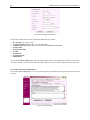
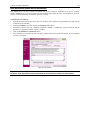
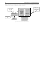
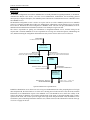
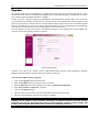
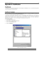
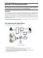
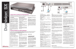
1
Installation and
Operations Manual
SX16
SX32
This page intentionally left blank.
Installation and
Operations Manual
SX16
SX32
C
UL
US
1F61
I.T.E.
LISTED
Copyright ©2003 Raritan Computer, Inc.
DSX-0A-E
October 2003
255-60-2000
Raritan Computer Inc.
400 Cottontail Lane
Somerset, NJ 08873
USA
Tel. 1-732-764-8886
Fax. 1-732-764-8887
[email protected]
http://www.raritan.com
Raritan Computer Europe, B.V.
Eglantierbaan 16
2908 LV Capelle aan den IJssel
The Netherlands
Tel. 31-10-284-4040
Fax. 31-10-284-4049
[email protected]
http://www.raritan.com
Raritan Computer Japan, Inc.
Kuga Building 7F
11-6, Kuramae 4-chome
Taitoo-ku, Tokyo 111-0051, Japan
Tel. 81-3-5833-6360
Fax. 81-3-5833-6336
[email protected]
http://www.raritan.co.jp
Raritan Computer Taiwan, Inc.
5F, 121, Lane 235,
Pao-Chiao Rd., Hsin Tien
Taipei Hsien, Taiwan, ROC
Tel. 886-2-8919-1333
Fax. 886-2-8919-1338
[email protected]
http://www.raritan.com.tw
This page intentionally left blank.
Copyright and Trademark Information
This document contains proprietary information that is protected by copyright. All rights reserved. No part of this
document may be photocopied, reproduced, or translated into another language without express prior written
consent of Raritan Computer, Inc.
©Copyright 2003 Raritan Computer, Inc., Dominion™, RaritanConsole™, SecureChat™, Remote Power Control™,
Paragon®, Powerboard™ and the Raritan company logo are trademarks of Raritan Computer, Inc. All rights
reserved. Java® is a registered trademark of Sun Microsystems, Inc. Internet Explorer® is a registered trademark of
Microsoft Corporation. Netscape® and Netscape Navigator® are registered trademarks of Netscape Communication
Corporation. RC4® is a registered trademark of RSA Corporation. Other trademarks or registered trademarks are the
property of their respective holders.
EXPORT NOTICE
Dominion SX models contain 128-bit encryption software. Export of this product is restricted under U.S. law.
Information is available from the U.S. Department of Commerce, Bureau of Export Administration at
www.bxa.doc.gov.
Contact Raritan Technical Support Team at (732) 764-8886 or e-mail us at [email protected]
Ask for Technical Support – Monday through Friday, 8:00am to 8:00pm, EST.
This page intentionally left blank.
TABLE OF CONTENTS
i
Table of Contents
Chapter 1: Introduction ............................................................................1
Dominion SX Overview ...........................................................................................................................1
Product Photos .......................................................................................................................................1
Product Features ....................................................................................................................................1
Package Contents...................................................................................................................................2
Chapter 2: Installation .............................................................................3
Pre-Configuration Notes .........................................................................................................................3
Hardware Installation ..............................................................................................................................3
Initial Software Configuration ...........................................................................................................5
Configuration ....................................................................................................................................5
Step-by-Step Configuration ..............................................................................................................6
Time and Date Configuration ..................................................................................................................8
Deployment .............................................................................................................................................9
Chapter 3: Operation ..............................................................................11
Overview ...............................................................................................................................................11
Accessing the Remote Device ..............................................................................................................11
Browser-Based Access ..................................................................................................................11
Security Dialog for Console Display......................................................................................................13
Internet Explorer .............................................................................................................................13
Netscape Navigator ........................................................................................................................14
Sending a Break / Null ..........................................................................................................................15
Chapter 4: Console Features .................................................................17
Emulator................................................................................................................................................17
Settings...........................................................................................................................................17
History ............................................................................................................................................18
Write Access...................................................................................................................................19
User List .........................................................................................................................................21
Close ..............................................................................................................................................22
Edit ........................................................................................................................................................23
Tools .....................................................................................................................................................24
Start Logging ..................................................................................................................................24
Stop Logging ..................................................................................................................................25
Script .....................................................................................................................................................26
SecureChat ...........................................................................................................................................27
Help.......................................................................................................................................................28
Help Topics.....................................................................................................................................28
About RaritanConsole ....................................................................................................................29
Direct Port Access ................................................................................................................................30
URL with Password and Username and Port.................................................................................30
URL with Port Number....................................................................................................................31
Exit the Application ...............................................................................................................................32
Dominion SX Management ...................................................................................................................34
Display............................................................................................................................................34
Configuration Lock and the Configuration Save Commands .........................................................35
Update ............................................................................................................................................35
Save and Reload ............................................................................................................................35
Configuration.........................................................................................................................................37
Report.............................................................................................................................................37
Network ..........................................................................................................................................38
Ports ...............................................................................................................................................41
Users ..............................................................................................................................................43
IP ACL ............................................................................................................................................46
Certificate .......................................................................................................................................48
RADIUS ..........................................................................................................................................55
ii
TABLE OF CONTENTS
Time................................................................................................................................................59
Notification......................................................................................................................................60
Upgrade ................................................................................................................................................64
Reset.....................................................................................................................................................66
Soft Reset.......................................................................................................................................66
Factory Reset .................................................................................................................................67
Chapter 5: Dominion SX Connectivity and Serial Pin-Out Guides .........69
Connectivity Table: ...............................................................................................................................69
Dominion SX Serial Pinouts..................................................................................................................69
Appendix A: Specifications ....................................................................71
Appendix B: System Defaults.................................................................73
Appendix C: Certificates ........................................................................75
Certificate ..............................................................................................................................................75
Certificate Contents ........................................................................................................................75
Certificate Authority ........................................................................................................................76
Installing Dominion SX CA-Root Certificate to a Browser ....................................................................77
Installing CA Root for IE Browsers .......................................................................................................78
Accept a Certificate (Session-Based).............................................................................................78
Install the Raritan Root Certificate..................................................................................................78
Remove an Accepted Certificate....................................................................................................81
Install CA Root for Netscape Navigator ................................................................................................82
Accept a Certificate (Session-Based).............................................................................................82
Install the Dominion SX Root Certificate ........................................................................................83
Remove an Accepted Certificate....................................................................................................85
Install a Third-Party Root Certificate .....................................................................................................86
Appendix D: RADIUS Server ...................................................................89
Overview ...............................................................................................................................................89
Install and Configure the RADIUS Server for Windows 2000...............................................................90
Appendix E: Configuring Cisco ACS RADIUS Server .............................97
Appendix F: RSA ACE/Server Configuration.........................................101
Appendix G: Modem Configuration ......................................................107
Client Dialup Networking Configuration ..............................................................................................107
Windows NT Dialup Networking Configuration...................................................................................107
Windows 98 Dialup Networking Configuration....................................................................................109
Windows 2000 Dialup Networking Configuration................................................................................111
Appendix H: Client Software Installation ............................................115
IE on Windows NT/2000/98 ................................................................................................................115
Netscape on Windows NT/2000/98 ....................................................................................................116
Remove RaritanConsole on Windows NT/2000/98 ............................................................................117
With IE ..........................................................................................................................................117
With Netscape ..............................................................................................................................117
Client for Sun Solaris and other UNIX platforms ................................................................................117
Netscape Installation ....................................................................................................................117
Appendix I: TCL Programming Guide...................................................119
Overview .............................................................................................................................................119
TCL Architecture with Target System .................................................................................................119
Boot Script Support ......................................................................................................................121
File System...................................................................................................................................121
TABLE OF CONTENTS
iii
File Directory Structure.................................................................................................................121
File System API through TCL.......................................................................................................121
TCL Commands ...........................................................................................................................122
Accessing TCL Window ...............................................................................................................123
Resetting TCL Interpreter.............................................................................................................123
Editing TCL Scripts.......................................................................................................................123
Executing TCL Scripts ..................................................................................................................124
Automatic Execution of a TCL Script upon Power Up..................................................................124
Generating a User Event ....................................................................................................................125
Extensions to TCL...............................................................................................................................126
Basic TCL Server Example.................................................................................................................135
Basic CPU Utilization Monitoring Example .........................................................................................136
TCL Server designed to interact with a TCL user ........................................................................139
Appendix J: Troubleshooting ...............................................................141
Problems and Suggested Solutions....................................................................................................141
Page Access.................................................................................................................................141
Firewall .........................................................................................................................................142
Login.............................................................................................................................................142
Port Access ..................................................................................................................................143
Upgrade........................................................................................................................................143
Modem..........................................................................................................................................143
Appendix K: Technical FAQs ...............................................................145
iv
TABLE OF CONTENTS
TABLE OF FIGURES
v
Table of Figures
Figure 1 Dominion SX32 Unit........................................................................................................................1
Figure 2 Rear Panel ......................................................................................................................................3
Figure 3 Default Settings for Factory Reset Mode ........................................................................................4
Figure 4 Hardware Setup for Initial Software Configuration..........................................................................5
Figure 5 Initial Configuration showing Physical Installation was successful .................................................6
Figure 6 Initial Configuration screen for the First Administrator Account......................................................7
Figure 7 Initial Configuration screen for Network Settings ............................................................................7
Figure 8 End of Initial Setup ..........................................................................................................................8
Figure 9 Time Configuration Display .............................................................................................................8
Figure 10 Deployment ...................................................................................................................................9
Figure 11 Security Alert Display ..................................................................................................................11
Figure 12 Login Display...............................................................................................................................12
Figure 13 Main Display with Available Ports ...............................................................................................12
Figure 14 Security Dialog in Internet Explorer.............................................................................................13
Figure 15 Security Dialog for Logging in Netscape Navigator ....................................................................14
Figure 16 Security Dialog for Copy Paste in Netscape Navigator ..............................................................14
Figure 17 Console Window .........................................................................................................................15
Figure 18 Settings Command and Settings Window...................................................................................17
Figure 19 History Command .......................................................................................................................18
Figure 20 Get Write Access Command.......................................................................................................19
Figure 21 Console without Write Access; with Write Access Warning Window..........................................20
Figure 22 User List Command and User List Window ................................................................................21
Figure 23 Close Command..........................................................................................................................22
Figure 24 Edit Commands - Copy, Paste, and Select All Text....................................................................23
Figure 25 Start Logging Command and Select File Window ......................................................................24
Figure 26 Stop Logging Command .............................................................................................................25
Figure 27 Script Shell Command ................................................................................................................26
Figure 28 SecureChat Command and User Chat Window .........................................................................27
Figure 29 Help Topics Command and Help File Window ...........................................................................28
Figure 30 About RaritanConsole Command and About Window ................................................................29
Figure 31 Direct Port Access Initial Display ................................................................................................30
Figure 32 Security Warning Display ............................................................................................................30
Figure 33 Direct Port Access Display..........................................................................................................31
Figure 34 Invalid Port Number Error Display ..............................................................................................31
Figure 35 Incomplete Parameter Error Display ...........................................................................................32
Figure 36 Save the Changed Configuration Window ..................................................................................32
Figure 37 Exit Confirmation Display ............................................................................................................33
Figure 38 Unit Disconnection Display .........................................................................................................33
Figure 39 Display Overview.........................................................................................................................34
Figure 40 Report Display.............................................................................................................................37
Figure 41 Network Configuration Display....................................................................................................38
Figure 42 Modem Connection to a Dominion SX unit .................................................................................40
Figure 43 Port Configuration Display ..........................................................................................................41
vi
TABLE OF FIGURES
Figure 44 Port Editing Display.....................................................................................................................41
Figure 45 Users Tab Display.......................................................................................................................43
Figure 46 New User Creation ......................................................................................................................44
Figure 47 User Modification ........................................................................................................................45
Figure 48 IP ACL Configuration Display......................................................................................................46
Figure 49 Invalid Subnet Mask Message ....................................................................................................47
Figure 50 Certificate Tab Display ................................................................................................................48
Figure 51 Certificate Configuration Display.................................................................................................49
Figure 52 Generate Certificate Display .......................................................................................................50
Figure 53 View Self-Signed Certificate Display...........................................................................................50
Figure 54 Activating Default Certificate .......................................................................................................51
Figure 55 Generate CSR Request Display .................................................................................................51
Figure 56 CSR Configurable Parameters....................................................................................................52
Figure 57 View CSR Display .......................................................................................................................52
Figure 58 User Certificate............................................................................................................................53
Figure 59 Schematic of External Certificate Utilization ...............................................................................54
Figure 60 RADIUS Users Login Mechanism ...............................................................................................55
Figure 61 Unsuccessful Login Message Window .......................................................................................56
Figure 62 RADIUS Configuration Display ...................................................................................................57
Figure 63 Current Users List .......................................................................................................................58
Figure 64 Time Configuration Display .........................................................................................................59
Figure 65 Notification Display......................................................................................................................60
Figure 66 New Notification Display .............................................................................................................61
Figure 67 Edit Notification Destination ........................................................................................................62
Figure 68 Upgrade Display..........................................................................................................................64
Figure 69 Confirmation for Reset ................................................................................................................66
Figure 70 Confirmation on Users to be Disconnected ................................................................................66
Figure 71 Factory Reset Connector Location..............................................................................................67
Figure 72 Administrative Information...........................................................................................................75
Figure 73 Hierarchies of Certificate Authorities...........................................................................................76
Figure 74 Schematic Diagram of Certificate Authentication Scheme .........................................................77
Figure 75 Install Session Based Certificate.................................................................................................78
Figure 76 View of CA_ROOT.cer ................................................................................................................79
Figure 77 Certificate Manager Import Wizard .............................................................................................79
Figure 78 Import Wizard, Select a Certificate Page ....................................................................................80
Figure 79 Certificate Manager Import Wizard, Completion Page................................................................80
Figure 80 Internet Options Display..............................................................................................................81
Figure 81 Certificate Manager Display ........................................................................................................81
Figure 82 Netscape New Site Certificate Window ......................................................................................82
Figure 83 Netscape New Site Certificate Acceptance Window..................................................................82
Figure 84 Viewing the Certificate ................................................................................................................83
Figure 85 Netscape New Type Window ......................................................................................................83
Figure 86 Netscape New Certificate Authority Window ..............................................................................84
Figure 87 Netscape Web Site Certificates Window ....................................................................................85
Figure 88 Certificate Already Exists Alert Window for Netscape. ...............................................................86
TABLE OF FIGURES
vii
Figure 89 Certificate Signers’ Certificates Window in Netscape .................................................................86
Figure 90 New Certificate Authority Window in Netscape...........................................................................87
Figure 91 Cisco ACS Main Display ............................................................................................................97
Figure 92 Unit Configuration Display...........................................................................................................97
Figure 93 Interface Configuration Display ...................................................................................................98
Figure 94 RADIUS Properties Display ........................................................................................................98
Figure 95 New User Display.......................................................................................................................99
Figure 96 User Properties Display ..............................................................................................................99
Figure 97 Launching RSA Administration Application...............................................................................101
Figure 98 Add Agent Host Selection .........................................................................................................101
Figure 99 Add Agent Host Display ............................................................................................................102
Figure 100 RADIUS Secret Key Display ...................................................................................................102
Figure 101 Add Profile Selection...............................................................................................................103
Figure 102 Add Profile Display..................................................................................................................103
Figure 103 Add Attribute Display...............................................................................................................104
Figure 104 Add User Display ...................................................................................................................104
Figure 105 Profile Selection Display .........................................................................................................105
Figure 106 Unit Selection Display per User .............................................................................................105
Figure 107 Dial-Up Networking Display ....................................................................................................107
Figure 108 New Phone Entry Display .......................................................................................................108
Figure 109 Dial-Up Security Display .........................................................................................................108
Figure 110 Configuring Windows 98 Dialup Networking...........................................................................109
Figure 111 Make New Connection – Connection Name ...........................................................................109
Figure 112 Make New Connection – Complete ........................................................................................110
Figure 113 Connect Window .....................................................................................................................110
Figure 114 Windows 2000 Network and Dialup Connections ...................................................................111
Figure 115 Welcome to the Network Connection Wizard .........................................................................111
Figure 116 Network Connection Type.......................................................................................................112
Figure 117 Device Selection .....................................................................................................................112
Figure 118 Phone Number to Dial.............................................................................................................113
Figure 119 Connection Availability ............................................................................................................113
Figure 120 Network Connection Wizard Completion ................................................................................114
Figure 121 IE Client Download Display.....................................................................................................115
Figure 122 Raritan Plugin Security Warning Display ................................................................................115
Figure 123 Netscape Plugin Redirection Display......................................................................................116
Figure 124 TCL Architecture .....................................................................................................................119
Figure 125 Activating TCL Scripting Window ............................................................................................123
viii
TABLE OF FIGURES
CHAPTER 1: INTRODUCTION
1
Chapter 1: Introduction
Dominion SX Overview
The Dominion SX Series of Serial over IP Console Servers offers convenient and secure, remote access and control
via LAN/WAN, Internet or Dial-up modem of all networking devices. Dominion SX connects to any networking
device (servers, firewalls, load balancer, etc.) via the serial port and provides the ability to remotely and securely
manage the device using any Web browser. Dominion SX provides a non-intrusive solution for managing network
elements and does not require any software agents to be installed on the target device.
Product Photos
Dominion SX is a fully configured stand-alone product in a standard 1U 19” rack mount chassis
Figure 1 Dominion SX32 Unit
Product Features
Comprehensive Console Management
•
•
•
•
•
•
•
•
Remote Management: Access, monitor, administer, and troubleshoot up to 16 or 32 target devices (depending
on model) from any Web browser while consuming only one IP address.
Scripting: Create, store and execute scripts either on demand or on a continuous basis
Notification: Create notification messages via email alerts
Collaborative Management and Training: Access pots simultaneously; up to 10 users per port at any time.
SecureChat™: “Instant message” other users securely and collaborate on device management, troubleshooting,
and training activities.
Get History: Get up to 999 lines of recent console history to assist with debugging.
VT100 Console Window: View VT100 terminal emulation including copy/paste and record/playback
functionality.
Three Levels of User Access:
− Administrator: Has read and write access to the console window; can modify the configuration of unit.
− Operator: Has read and write access to the console window; cannot modify the configuration of unit
(except own password).
− Observer: Has read-only access to the console window; cannot modify the configuration of unit (except
own password).
2
DOMINION SX INSTALLATION AND OPERATIONS MANUAL
Strong Security and User-Authentication
•
•
•
•
Encryption Security: 128-bit Secure Socket Layer (SSL) handshake protocol and RC4 encryption.
User Authentication Security: Login Name and Password scheme (MD5 Hash) with global Access Control List
(ACL).
Supports RADIUS (can be configured as a RADIUS client).
Supports User-defined and installable security Certificates.
Reliable Connectivity
•
•
Modem Connectivity: For emergency remote access if the network has failed.
Target Device Connectivity: Simplified RJ45-based CAT5 cable scheme; serial port adapters are available from
Raritan.
Simplified User Experience
•
•
•
Browser-based Interface: Graphical User Interface provides intuitive access to target devices (click on the
appropriate button to select the desired target device).
Upgrades: Built-in firmware upgrade capability via FTP/Internet.
Ability to load specific applications per console port for ease of use; specific applications are available from
Raritan.
Package Contents
Each Dominion SX ships with the following:
•
•
•
•
•
(1) Dominion SX unit with mounting racks installed (Rackmount kit is optional on some units)
(1) Raritan User Manual CD-ROM containing the Dominion SX Installation and Operations Manual
(1) Power cord
(1) Release Note page
(1) Packing List page
CHAPTER 2: INSTALLATION
3
Chapter 2: Installation
This section describes the steps necessary to configure Dominion SX for use on a local area network (LAN). All
new Dominion SX units come with default network settings, illustrated in the table below. Once units are connected
to the network, these default settings will allow the user to configure Dominion SX for normal use.
There are three separate tasks you must complete to use Dominion SX on the network: Hardware Installation, Initial
Software Configuration, and Dominion SX Deployment, usually completed in this order, and each described in this
chapter.
Hardware Installation describes how to connect the Dominion SX unit to a computer to perform the initial
configuration of the unit. This step requires an additional computer that will be used to log into the Dominion SX
unit and configure it for the first time in the next section.
Initial Software Configuration describes how to connect to Dominion SX in its default state and to configure it for
use in a specific network environment.
Dominion SX Deployment describes how to install a Dominion SX unit on the network once the Initial Software
Configuration is complete.
Pre-Configuration Notes
The following list includes information that you will be required to supply to complete the configuration of the
Dominion SX. Obtain all required configuration information prior to performing the configuration steps outlined
below. If you are uncertain of any information, contact your system administrator for assistance.
Network Information:
•
•
•
•
•
Raritan Unit Name: The name of this unit, a generic term for the Dominion SX unit. This can be 64 characters
maximum, no minimum, no spaces.
IP address: The IP address of the unit, as directed by your network administrator.
IP subnet mask: The IP subnet mask for the unit, as directed by your network administrator.
IP gateway: The IP gateway for the unit, as directed by your network administrator.
Port Address: Any number from 2000 to 2400, as directed by your network administrator; default value is 23.
Choosing a number other than 23 can potentially improve security.
Hardware Installation
SelfTest and Factory Reset LED
Primary LAN Connection
RJ45 serial ports
Modem
Figure 2 Rear Panel
4
DOMINION SX INSTALLATION AND OPERATIONS MANUAL
Physical Installation of Dominion SX for Initial Configuration:
1. Obtain a computer with a network card and crossover network cable. This computer will be referred to as the
‘installation computer.’
2. A unique MAC address for each unit is shown on a sticker on the chassis. Make a note of this address prior to
physical installation.
3. Physically mount the unit in an ergonomically sound manner. The unit is designed to be easily rack-mounted,
and rack mounting is recommended.
4. Connect the crossover network LAN cable to the primary LAN connection on the back of the chassis. Connect
the other end to the network card in the installation computer.
5. Connect the female end of the external power cord to the back of the chassis.
6. Connect the male end of the external power cord to the power supply outlet. Power ON the Dominion SX unit.
Note: The unit will perform a hardware and firmware self-test, indicated by the green light on the
back of the chassis, and then start the software boot sequence. The boot sequence takes
approximately 30-60 seconds, and is complete when the green light goes on and remains on.
7.
Each unit comes with a certain set of configuration defaults henceforth referred to as Factory Reset Mode. The
default network settings for this mode are:
Internet Address (IP)
Gateway Address
Subnet Mask
Port Address
192.0.0.192
192.0.0.192
255.255.0.0
23
Figure 3 Default Settings for Factory Reset Mode
8.
Ensure that your installation computer can communicate with IP address 192.0.0.192. First, verify that the
installation computer has the route for 192.0.0.192:
a. On the command line interface of the installation computer, enter the command route print.
b. If 192.0.0.192 is on the gateway list, proceed to the next step. Otherwise, add 192.0.0.192 to the gateway
list: type the following commands into either a DOS or UNIX command line interface on the installation
computer where your browser is running:
i. On a Windows NT/95/98/2000 system: route add 192.0.0.192 <client_host IP address>
Example:
route add 192.0.0.192 15.128.122.12
ii. On a UNIX (incl. Sun Solaris) system: route add 192.0.0.192 <client_host IP address> -interface
Example:
route add 192.0.0.192 15.128.122.12 -interface
9. On the command line interface, type: ping 192.0.0.192.
a. If this command successfully produces a reply from the Dominion SX unit, please proceed to step 10.
b. If this does not produce a reply, verify that the default IP address is entered correctly and there is a route to
that IP address.
10. Use the installation computer to connect to the unit, typing the factory default IP address 192.0.0.192 in the
installation computer Web browser’s address line. Once you have reached the unit’s initial configuration screen,
proceed to the Initial Software Configuration section that follows.
CHAPTER 2: INSTALLATION
5
Initial Software Configuration
Crossover
Network
Cable
Dominion SX Unit
Browser
Installation
Computer
Figure 4 Hardware Setup for Initial Software Configuration
User Information:
This information should be entered for each user, up to 50 user accounts, with at least one administrator for each
Dominion SX unit:
•
•
•
•
•
User Name: 32 characters maximum, one character minimum, spaces permitted.
Login Name: 20 characters maximum, one character minimum, no spaces.
User Type:
− Administrator: Can modify configuration of the unit, has read/write access to the console window.
− Operator: Cannot modify configuration of the unit (except own password), has read/write access to the
console window.
− Observer: Cannot modify configuration of the unit (except own password), has read-only access to the
console window.
Information: Any additional information (text) you want associated with this user. Can be 64 characters
maximum, no minimum, spaces permitted.
Password: Alphanumeric text, 6–16 characters in length, no spaces. The first six characters of the password
must contain at least two alpha and one numeric character; the first four characters cannot be the same as the
user name.
Configuration
1.
2.
3.
4.
Disable Proxies in the installation computer Web browser.
Use “no Proxies” or temporarily add 192.0.0.192 to the list of URLs for which no proxy is configured.
Enable Java™ Applet Execution in the installation computer Web browser.
Access the unit through your installation computer Web browser on the same subnet by typing the URL
https://192.0.0.192 into the address/location field.
Follow the configuration instructions on the screen.
Note: At this point you will enter all of the initial configuration information listed in PreConfiguration Notes.
5.
The unit will reboot automatically once it has been configured. The unit now has the user-defined configuration
settings, including a new IP address and is ready to be powered off, disconnected from the installation computer,
and moved to its intended location.
6
DOMINION SX INSTALLATION AND OPERATIONS MANUAL
Step-by-Step Configuration
1.
Access the unit through your Web browser on an installation computer that is on the same subnet by typing the
URL: https://192.0.0.192.
Figure 5 Initial Configuration showing Physical Installation was successful
2.
Click on the [Next] button to add users.
CHAPTER 2: INSTALLATION
3.
7
When the User Configuration Window appears, enter the information for the first user for Dominion SX. By
default, the first user will have Administrator privileges. All fields except for the Information field are required.
−
−
−
−
−
Name: User’s (real) name
Information: Descriptive information about this user
Login Name: Unique login identifier
Password: User’s password
Re-enter Password: Confirm password by re-typing it
Figure 6 Initial Configuration screen for the First Administrator Account
4.
5.
Click on the [Next] button to proceed to the Network Configuration window.
The Network Configuration Window allows the user to specify the network settings for the unit. A network
administrator typically assigns the values for these parameters. All fields are required:
−
−
−
−
−
−
Raritan Unit Name: Descriptive name for this unit
IP Address: Network address for this unit
Subnet Mask: Subnet mask for the network where this unit will reside
IP Gateway: Default gateway for this unit
Port Address: Default application communication port
Terminal Type: Terminal emulation type; fixed vT100
Figure 7 Initial Configuration screen for Network Settings
8
DOMINION SX INSTALLATION AND OPERATIONS MANUAL
6.
Click on the [Finish] button to complete the initial configuration of Dominion SX. You will see a screen that
indicates successful configuration of the unit. The system will reboot and apply the new settings.
Figure 8 End of Initial Setup
Time and Date Configuration
We recommend that you configure the local Date and Time in the Dominion SX unit as soon as it is configured.
Some features in Dominion SX, for example, Certificate generation, depend on the correct Timestamp, which is
used to check the validity period of the certificate.
Figure 9 Time Configuration Display
Configuration
7.
8.
9.
Set the Current Date and Current Time.
Click on the [Update] button.
Click on the [Save] button.
CHAPTER 2: INSTALLATION
9
Deployment
After the Initial Software Configuration phase, a Dominion SX unit is configured for operation on the LAN.
Ethernet
Connection
Browser
Dominion SX Unit
Installation
Computer
LAN
Figure 10 Deployment
1.
2.
3.
4.
5.
6.
7.
Make sure you have an allocated Ethernet cable connected to the network for use with the unit.
Physically mount the unit in an ergonomically sound manner.
Connect the LAN cable to the primary LAN connection on the back of the chassis. Connect and/or verify that
the other end of the cable is connected to the proper network. If the unit has a failover module, connect the
secondary network LAN connection as well.
Connect the female end of the external power cord to the back of the chassis.
Serial Connection to Target Devices: This manual contains detailed information on connecting the Dominion
SX unit to the console port of target devices.
Modem Connection (optional): Connect a phone line to the modem port. Remember to write down the phone
number for this line, as it will be necessary later when the user configures a client for dialup networking.
Connect the male end of the external power cord to the power supply outlet and power ON the Dominion SX
unit.
Note: The unit will perform hardware and firmware self-test, indicated by the green light on the
back of the chassis, and then start the software boot sequence. The boot sequence takes
approximately 30-60 seconds and is complete when the green light goes out.
8.
9.
Perform a quick connectivity check by connecting to the device using either IE or Netscape. In the address line,
enter https://<IPAddress> where IPAddress is the IP address of the unit as previously configured. The login
display should appear verifying that the unit has been properly configured and can be accessed from the
network.
Enter the Configuration window and enter the various configuration parameters for each console port. Enter
specific operational parameters for the unit (please see Chapter 4: Console Features for additional
information).
10
DOMINION SX INSTALLATION AND OPERATIONS MANUAL
CHAPTER 3: OPERATION
11
Chapter 3: Operation
Overview
Once the Dominion SX unit has been deployed in its final destination, you can access the console of the target
device. This chapter explains the normal operational procedures.
Accessing the Remote Device
The remote device can be accessed in one of two ways, either browser-based or by direct port access, used either as
a user based remote device access method or used for application programs to access the target device
programmatically.
Note: For the purpose of illustration, all discussion in this manual is based on using Internet
Explorer as the browser.
Browser-Based Access
1.
Using a browser (IE or Netscape) on your client desktop, enter the IP address of the unit. A security alert
window will appear.
Figure 11 Security Alert Display
2.
The unit is always SSL enabled. When you try to connect to the Dominion SX unit, a Security Alert is
displayed ; this is because the CA root certificate is not installed in the browser. Please see Appendix C:
Certificates for additional information.
Click on the [Yes] button to continue.
12
3.
DOMINION SX INSTALLATION AND OPERATIONS MANUAL
When the login screen appears, enter your Login Name and Password, and click on the [Login] button.
Figure 12 Login Display
4.
When the main display page appears, click on the desired [Port#] button to launch that port’s console display.
Figure 13 Main Display with Available Ports
CHAPTER 3: OPERATION
13
Security Dialog for Console Display
RaritanConsole, an applet included with your Dominion SX unit, is designed by Raritan to enable the applet to
access the resources of the user’s computer. Both the copy and paste and the logging features of these applications
require the use of the client computer system resources. Both operations require the user’s permission to operate,
and Internet Explorer and Netscape Navigator request these permissions in different fashions. In addition, the default
code set preferences are stored on the user’s computer.
Internet Explorer
Before the RaritanConsole window appears, a Security Warning screen requests permission to access computer
resources. The dialog indicates that the authenticity of the signer, Raritan, has been verified by Thawte Server CA,
and it specifies the permissions requested from the user.
Figure 14 Security Dialog in Internet Explorer
•
•
Click on the [Yes] button to accept all requested permissions. These permissions will not be requested again in
the same session. Check the [Always trust content from…] checkbox to avoid being asked for permissions at
the start of every new session.
Click on the [No] button on the dialog box cancels the RaritanConsole window.
Important! Once [No] is selected, the console will not pop up until the browser is closed and a new
session is started.
14
DOMINION SX INSTALLATION AND OPERATIONS MANUAL
Netscape Navigator
RaritanConsole loads without displaying a Security Warning window. When actions that require user permissions
are performed, a security dialog will appear. Each operation requires a unique permission. The Start Logging and
Copy/Paste operations will prompt the user with a security dialog window. Once permissions are granted, they will
not be requested again in the same session. Users can also check the [Remember this decision] checkbox to avoid
being asked for permissions every new session.
Figure 15 Security Dialog for Logging in Netscape Navigator
Figure 16 Security Dialog for Copy Paste in Netscape Navigator
CHAPTER 3: OPERATION
15
Once the Security screens are completed, the console window appears, and the user can begin working with the
remote target system.
Figure 17 Console Window
Sending a Break / Null
Some target systems, such as Sun Servers, require a null character (Break) to be sent from the console. Pressing the
<F8> function key sends a null character to the target device. To send a break / null:
1. Verify that you have write access. If not, you can either press the <F8> key, or can use the drop-down menu to
obtain write access, as described in the Write Access section of Chapter 4: Console Features.
2. Press the <F8> key to send the break / null.
Note: <F8> is a multifunction key. It is used to obtain write access when the user does not have write access and is
also used to send a break / null character to the remote target system once the user obtains write access.
16
DOMINION SX INSTALLATION AND OPERATIONS MANUAL
CHAPTER 4: CONSOLE FEATURES
17
Chapter 4: Console Features
There are six drop-down menus available in the menu bar of the console window:
•
•
•
•
•
•
Emulator
Edit
Chat
Tools
Script
Help
Emulator
Settings
The Settings window displays the Buffer Size, Terminal Type, and Cursor Type for the console window.
•
•
•
The Buffer Size is preset to 999 lines and cannot be changed.
Currently the unit supports only Terminal Type vt100, which cannot be changed.
The Cursor Type can be either Line or Block, depending on your preference. The default cursor is Line type,
but can be changed by clicking on the appropriate radio button.
To View Settings:
1. Click on Emulator in the main menu.
2. Select Settings from the drop-down menu.
Figure 18 Settings Command and Settings Window
3.
4.
Adjust settings as needed.
Click on the [OK] button to close the Settings window.
18
DOMINION SX INSTALLATION AND OPERATIONS MANUAL
History
The History feature allows you to view the recent history of console sessions by displaying the console messages to
and from the target device. This function displays up to 999 lines of recent console message history, allowing a user
to see target device events over time. When the 1000th line entry is reached, the text will wrap, overriding the oldest
data with the newest. History information can be useful when debugging, troubleshooting, or administering a target
device.
Note: History data is displayed only to the user who requested the history.
To View Session History:
1. Click on Emulator in the main menu.
2. Select History from the drop-down menu.
Figure 19 History Command
CHAPTER 4: CONSOLE FEATURES
19
Write Access
The user with Write Access can send commands to the target device. Write Access can be transferred among users
working in RaritanConsole via the Get Write Access command or by using the <F8> key (please see Chapter 2:
Operation for additional details).
To Obtain Write Access:
1. Click on Emulator in the main menu.
2. Select Get Write Access from the drop-down menu.
Figure 20 Get Write Access Command
3.
You now have Write Access to the target device, as indicated by the green block located before Write Access in
the status bar.
20
DOMINION SX INSTALLATION AND OPERATIONS MANUAL
4.
When another user assumes Write Access from you, a modal display will appear on your screen. Loss of Write
Access is indicated by a red block before Write Access in the status bar. The modal display appears only on the
screen of the user who currently has Write Access.
Figure 21 Console without Write Access; with Write Access Warning Window
Note: <F8> is a multifunction key: use it to obtain write access, and also to send a null/break
character to the remote target system.
CHAPTER 4: CONSOLE FEATURES
21
User List
The User List command allows you to view a list of other users who are accessing the same port. An asterisk (*)
appears before the user who has Write Access to the console.
To View the User List:
1. Click on Emulator in the main menu.
2. Select User List from the drop-down menu.
Figure 22 User List Command and User List Window
3.
Click on the [Close] button to close the User List window.
22
DOMINION SX INSTALLATION AND OPERATIONS MANUAL
Close
To Close RaritanConsole:
1. Click on Emulator in the main menu.
2. Select Close from the drop-down menu.
Figure 23 Close Command
CHAPTER 4: CONSOLE FEATURES
23
Edit
Use the Copy, Paste, and Select All Text commands to relocate and / or re-use important text.
Figure 24 Edit Commands - Copy, Paste, and Select All Text
To Copy and Paste All Text:
1. Click on Edit in the main menu.
2. Select Select All Text from the drop-down menu.
3. Click on Edit in the main menu.
4. Select Copy from the drop-down menu.
5. Position the cursor at the location you wish to paste the text and click once to make that location active.
6. Click on Edit in the main menu.
7. Select Paste from the drop-down menu.
Note: There are keyboard shortcuts that you can use to highlight, copy, and paste all or partial
lines of text:
- Click and drag your mouse over the text you wish to copy
- Press <CTRL> and tap the <C> key to copy
- Position the cursor where you wish to paste the text and click in that location to make it active
- Press <CTRL> and tap the <V> key to paste
24
DOMINION SX INSTALLATION AND OPERATIONS MANUAL
Tools
Raw console data from the target device can be logged to a file in your computer. The Logging indicator on the
status bar indicates whether Logging is on or off.
Start Logging
1.
2.
3.
Click on Tools in the main menu.
Select Start Logging from the drop-down menu.
Choose an existing file or provide a new file name in the File Dialog box. When an existing file is selected for
logging, data gets appended to the contents. Providing a new file name creates a brand new file. Click on the
[OK] button after you have selected or created a file.
Logging is Off until
the Start Logging
command is
executed.
Figure 25 Start Logging Command and Select File Window
CHAPTER 4: CONSOLE FEATURES
25
Stop Logging
1.
2.
Click on Tools in the main menu.
Select Stop Logging from the drop-down menu.
Logging is On until
the Stop Logging
command is
executed.
Figure 26 Stop Logging Command
26
DOMINION SX INSTALLATION AND OPERATIONS MANUAL
Script
RaritanConsole supports TCL version 7.0, an industry standard scripting engine. Using TCL scripting capabilities,
system administrators can create their own conditions for event detection, and generate customer-specific
notifications and alerts. The unit features a TCL engine and a flash file system for the development and storage of
TCL scripts. Please see Appendix I: TCL Programming Guide for additional information.
RaritanConsole also comes with User Definable Events that can be generated by TCL scripts. Raritan has introduced
an extension library to provide an API to the RaritanConsole’s functions. Additionally, the unit comes with an
extensive list of notification events that can be used to audit, track and trace the conditions of and modifications to
the unit itself.
To Invoke the Script Shell:
1. Click on Script in the main menu.
2. Select Script Shell from the drop-down menu.
Figure 27 Script Shell Command
3.
4.
Enter your command or script and press the <Enter> key (please refer to Appendix I: TCL Programming
Guide for more information).
To reset the script, click on the [Reset] button on the Script Shell window.
CHAPTER 4: CONSOLE FEATURES
27
SecureChat
A real-time interactive chat feature called SecureChat provides you and other users who are accessing the console
port of the target device to conduct an online dialog for training or collaborative diagnostic activities.
To use SecureChat:
1. Click on Chat in the main menu.
2. Select User Chat from the drop-down menu.
Figure 28 SecureChat Command and User Chat Window
3.
4.
Type a message in the Message text field.
Click on the [Send] button to send the message, click on the [Clear] button to delete the typed text, or click on
the [Close] button to exit and close the Message window.
Note: When a chat is initiated, a chat window will appear on the monitors of all users logged on
to the port.
28
DOMINION SX INSTALLATION AND OPERATIONS MANUAL
Help
Help Topics include on-line assistance for operating RaritanConsole and the console window, and Release
information about RaritanConsole.
Help Topics
To Access Help Topics:
1. Click on Help in the main menu.
2. Select Help Topics from the drop-down menu.
Figure 29 Help Topics Command and Help File Window
3.
Use the navigation bar on the right side of the window to scroll to the topic you need, or click on the links.
Close this window when you are finished.
CHAPTER 4: CONSOLE FEATURES
29
About RaritanConsole
The ‘About’ window displays version information (name and revision number) for the console terminal emulation
software, and copyright information. When contacting Raritan for technical support when performing a software
upgrade, etc., you may be asked for this information.
To Access ‘About’ Information:
1. Click on Help in the main menu.
2. Select About RaritanConsole from the drop-down menu.
Figure 30 About RaritanConsole Command and About Window
3.
Click on the [OK] button to close the About RaritanConsole window.
30
DOMINION SX INSTALLATION AND OPERATIONS MANUAL
Direct Port Access
This approach provides a quick and direct method of connecting to the console port in order to access unit
programmability or the console of the target device directly. There are two ways to access the target device console
directly by giving the appropriate URL.
URL with Password and Username and Port
1.
Type the following URL into the browser's location bar:
https://<IPAddress>/dpa.htm?username="username"?password="password"?port="portnumber”
−
IPAddress: This is the IP Address of the unit – either the actual IP address of the unit or IPAddress
assigned for a modem
− “username”: Login name
− “password”: Password
− “portnumber”: Port number for which a console is required
Example:
https://192.168.50.81/dpa.htm?username="raritan1"?password="rar123"?port="1”
2.
3.
4.
The Direct Port Access display will appear.
When the security warning appears (only once for the session); click on the [Yes] button.
The console display will appear.
Note: The user’s password will appear in the URL location bar.
Figure 31 Direct Port Access Initial Display
Figure 32 Security Warning Display
Important! This kind of access will generally be used in applications where the user name and password
is retrieved from a database. It is not advisable to place this URL in a HTML page where the user name
and password are visible.
CHAPTER 4: CONSOLE FEATURES
31
URL with Port Number
1.
Type the following URL into the browser's location bar: https://<IPAddress>/dpa.htm?port="portnumber"
−
IPAddress: This is the IP Address of the unit. This can be either the actual IP address of the unit or
IPAddress assigned for a modem.
− “portnumber”: Port number for which a console is required.
Example:
https://192.168.50.81/dpa.htm?port="2”
2.
3.
4.
5.
The Direct Port Access display will appear.
Enter Login Name and Password and click on the [Login] button.
When the security warning appears (only once for the session); click on the [Yes] button.
The console display will appear.
Figure 33 Direct Port Access Display
Error Conditions
If the user name, password, or port number is invalid or incomplete, an error message will be displayed in the
browser.
Invalid Port Specified:
If the port specified in the URL is invalid, the user is requested to login again with the correct user name and
password, and a valid port number:
Figure 34 Invalid Port Number Error Display
32
DOMINION SX INSTALLATION AND OPERATIONS MANUAL
Incomplete Parameters Specified:
If the parameters specified in the URL are incomplete, for example, if only the user name and port number are
specified and password is omitted in the URL, the user is alerted that there is missing information.
Figure 35 Incomplete Parameter Error Display
Exit the Application
Click on the [Exit] button in the left panel of the Dominion SX window to exit Dominion SX.
If changes to the configuration have been made but not saved, a screen will prompt you to save changes and log out
of the unit. Click on the [Yes] button to save changes and exit, or click on the [Cancel] button to return to the
configuration.
Figure 36 Save the Changed Configuration Window
CHAPTER 4: CONSOLE FEATURES
33
If changes have been saved already, the unit will confirm the request to exit. Click on the [OK] button to log out of
the unit.
Figure 37 Exit Confirmation Display
A confirmation screen will indicate disconnection from the unit.
Figure 38 Unit Disconnection Display
34
DOMINION SX INSTALLATION AND OPERATIONS MANUAL
Dominion SX Management
Aside from providing the capability to manage a remote target device, Dominion SX has a number of powerful
built-in features and capabilities available to manage the unit itself. With Dominion SX, users can:
•
•
•
•
•
•
•
•
•
Upgrade the software remotely via the network
Perform a soft reset on the application
Change network parameters
Add and Delete users and assign permission classes to each user
Increase security using RADIUS
Use the modem for out-of-band access
Restrict access based on IP address
Install a user-generated certificate or request a CSR to allow creation of a third-party certificate
Install custom applications per port
In each case, dedicated displays are provided to allow the adjustment and configuration of the various parameters.
Display
The display structure is divided into a number of key operational areas:
Help Button
Information
Button
Operational
Command
Buttons
Configuration
Tabs
Configuration
Save
Commands
Current
Users
Display
Figure 39 Display Overview
•
•
•
•
Operational Command Buttons: Used to modify operation of Dominion SX
− Port Access: Connects and displays the remote target device to be managed
− Configuration: Calls up the Configuration Tabs
− Upgrade: Provides a utility to upgrade Dominion SX software through the network
− Reset: Allows a soft reset of the application
− Exit: Logs out of the application and closes the connection to Dominion SX
Current Users Display: Indicates users who are currently connected to Dominion SX
Help Button: Brings up an online help guide on how to use the product
Information Button: Provides copyright notice and software version information
CHAPTER 4: CONSOLE FEATURES
•
•
35
Configuration Tabs: Displays several screens in which the user configures different elements of the
application
Configuration Save Commands: Used to save or ignore changes made to configuration
Configuration Lock and the Configuration Save Commands
Dominion SX is designed to allow only one user to configure it at any given time. When a user clicks on any of the
Configuration tabs, that user acquires the Configuration Lock, preventing others from modifying the configurations.
Other users may click on Configuration tabs at the same time, but will view all data in Read-only mode. Only after
the lock is released can another user modify configurations.
To Release the Configuration Lock:
•
•
•
Save the Configuration Changes: Saving the configuration commits the updated information to the unit and
automatically releases the Configuration Lock.
Reload the Previous Configuration: Reloading the previous configuration deletes all updated information,
reverts to the previously saved data, and automatically releases the Configuration Lock.
Unlock the Configuration: Clicking on the [Unlock Config] button located in the lower right corner of all
Configuration screens releases the Configuration Lock only if the user has not updated any configuration
changes. If any changes have been updated, only a Save or a Reload can unlock the configuration.
Note: Releasing the configuration lock loses any changes that are not updated.
Important! It is advisable to release the configuration lock once all necessary changes are made. This
leaves the configuration available in the event that other users have to make modifications to the device.
Update
Many of the Configuration tab screens feature an [Update] button. A user would click on the [Update] button to
notify the system that changes have been made in that Configuration screen. The configuration changes do not take
effect until they are saved. This offers two convenient advantages:
•
•
The user can make as many changes as intended in any number of tabs and just keep the changes updated. All
changes could be committed to take effect when desired with a single Save operation.
The user can reject all changes made in a single session using the Reload option, offering a higher degree of
error tolerance for the system. Any accidental deletions or modifications could be rolled back without having to
log out of the unit.
Save and Reload
Users can apply configuration changes to the Dominion SX unit by clicking on the [Save] button after editing
Configuration screens. Users can reject all the configuration changes using the [Reload] button, but it is important to
remember that configuration changes cannot be reloaded once they are saved.
To Save Configuration Changes:
1. Click on the [Configuration] button in the left panel.
2. Click on the tab(s) for the screens in which you want to make configuration changes.
3. When the status bar displays the Configuration locked message, other users cannot modify the unit’s
configuration.
4. Modify data in the screen and click on the [Update] button.
5. The status bar will display the message: Configuration changes not saved.
6. Click on the [Save] button.
36
DOMINION SX INSTALLATION AND OPERATIONS MANUAL
Note: If you are making changes to several different configuration screens in one session, click on
the [Update] button in each screen, but wait until making changes in the final configuration
screen, and then click on the [Save] button to save all changes with just one action.
7.
The status bar displays the message: Save in progress…
Note: If changes are made in the Network and Modem configuration screens, a warning message
alerts the user to the automatic system reboot upon the completion of the save.
8.
9.
A success message appears.
The Report screen is updated and displayed after a successful Save.
To Reload Configuration Changes:
1. Click on the [Configuration] button in the left panel.
2. Click on the tab(s) for the screens in which you want to make configuration changes.
3. When the status bar displays the Configuration locked message, other users cannot modify the unit’s
configuration.
4. Modify data in the screen, and click on the [Update] button.
5. The status bar will display the message: Configuration changes not saved.
6. Click on the [Reload] button to erase any changes in this and any other configuration screen.
7. A successful reload message appears, indicating a successful reload of the original settings and configuration
values.
8. The Report screen shows that no data has been changed.
CHAPTER 4: CONSOLE FEATURES
37
Configuration
Report
Overview
The Report configuration screen displays detailed information on how the Dominion SX has been configured, which
can be useful if debugging or troubleshooting.
•
•
•
•
•
•
•
•
•
System time and date
Ethernet address
Network configuration (IP address, subnet mask, and gateway)
Certificate configuration
Port configuration
Number of user accounts configured
IP ACL configuration
RADIUS configuration
Modem configuration
Figure 40 Report Display
38
DOMINION SX INSTALLATION AND OPERATIONS MANUAL
Network
Overview
The Network configuration screen provides an area for Administrators to define both the network and modem
(optional) settings for the unit.
Figure 41 Network Configuration Display
Some Dominion SX units comes equipped with a 56Kbps (bits per second) modem, which allows dial-in access to
the unit from virtually any location in the world. On other Dominion SX units, there is a connector on the rear panel
for a user-supplied external modem. Client computers connect to the unit by establishing a PPP (Point-to-Point
Protocol) link between the client machine and the Dominion SX unit. Once the PPP connection is established, the
client computer is physically on the same network as the Dominion SX unit and can access the unit using Internet
Explorer or Netscape browsers.
There are three requirements for dialing into the unit:
1. The phone line to the unit must be connected.
2. The modem / PPP connection settings must be configured.
3. The dial-up networking software on the user’s personal computer must be configured to establish a PPP
connection from the client computer to the unit.
Configure Network Parameters
•
•
•
•
•
•
IP address: IP address for the unit
IP subnet mask: Subnet mask to be used when deployed in the network
IP gateway: Gateway that the unit uses to communicate with other systems that are not on the same subnet
Dominion SX Unit Name: Name to be associated with the unit, 64 characters in length. Valid characters are AZ, a-z, -, _, 0-9, no spaces or special characters allowed
Terminal Type: Type of terminal supported; default is VT100
Port Address: Port address to be used by the unit when communicating with other systems; the default port
address is 23, but can also be set to any value in the range of 2000-2400 (please verify this value with your
firewall administrator)
Click on the [Update] button to load all the changes.
Click on the [Save] button to make the changes permanent.
Important! Remember that saving changes to Network Configuration settings will cause the unit to reboot.
CHAPTER 4: CONSOLE FEATURES
39
The parameters for configuring modem access include:
PARAMETER
Enable Modem
PPP Server IP
PPP Client IP
DESCRIPTION
Configures the modem to answer calls
IP address of the PPP server (Dominion SX unit)
IP address of the PPP client (remote computer)
Configure Modem Parameters
1.
2.
3.
4.
5.
Check the Enable Modem box.
Enter the PPP Server IP – the IP address used by the client to access Dominion SX once the modem connection
is established.
Enter the PPP Client IP – the IP address assigned by Dominion SX to the client in order for the connection to be
established.
Click on the [Update] button.
Click on the [Save] button.
The Modem Status field indicates one of two states:
•
•
Running: The modem is configured and is operational.
Stopped: The modem is not operational.
The [Initialize Modem] button can be used to reset the modem if it is running but not operating properly.
Note: Be sure to verify the above information with your Network Administrator prior to
configuring the unit.
When using Microsoft Windows, once Microsoft dial-up networking has established a connection, a network is
constructed with the parameters specified in the Modem Settings area of the Network configuration window. The
client computer now can be connected to two separate networks. These networks must have distinct IP addresses if
modem access is to function properly. The second network established by the PPP connection has only two devices,
the Dominion SX unit with IP address PPP Server IP and the client computer with IP address PPP Client IP.
Please see Appendix G: Modem Configuration for additional information on configuring Microsoft dial-up
networking on Windows 2000, Windows 98, and Windows NT.
40
DOMINION SX INSTALLATION AND OPERATIONS MANUAL
Modem Usage
Dial-up connection support for the unit allows users to access the connected target device when normal network
connectivity to Dominion SX is not available. Once the PPP connection is established between the client computer
and the unit, the user can access the unit by using the browser.
Note: Dial-up access is supported only with connections of 28.8 Kbps or greater connection baud
rates.
LAN
User’s PC
Internet
Dominion SX Unit
PPP Network
Phone Line
Modem
User’s PC
Figure 42 Modem Connection to a Dominion SX unit
Client Installation for Modem Access
Depending on the characteristics of the phone line, connection speed will vary. The modem that is installed in the
unit is a 56Kbps device; generally the connection speed will be approximately 33Kbps. At this speed, there is a
possibility that downloading the applet will take some time before a connection can be made with the unit and the
remote target device accessed. A client installation that improves the access to the unit is available, and once
installed, subsequent access to the unit makes use of this local file. Depending on the client machine browser
operating system that is used, the client software installation procedure is different. Please see Appendix H: Client
Software Installation for additional information.
CHAPTER 4: CONSOLE FEATURES
41
Ports
Overview
The Ports configuration screen allows Administrators to define the serial/console port settings in order to
communicate with remote target devices.
Figure 43 Port Configuration Display
Figure 44 Port Editing Display
Configure Port Parameters
•
•
•
•
Name: Name that associates the serial port with the connected target device; can be up to 64 characters in
length and must be unique from the other port names
Application: Application type that is associated with a specific port; default application provided is
RaritanConsole (contact Raritan for additional applications)
Baud rate: Baud rate of the serial port; should match that of the target device connected to the port (valid
choices are 1200, 1800, 2400, 4800, 9600, 19200, 28800, 38400, 57600, 115200)
Parity/Data bits: Parity/Data of the serial port; should match the setting of the target device (valid choices are
None/8, Even/7, Odd/7)
42
•
•
•
DOMINION SX INSTALLATION AND OPERATIONS MANUAL
Parity check: Enabling or disabling of the Parity function of the serial port; should also match the target
device’s setting
Xon/Xoff: Can be enabled if the target system supports this feature; will allow the unit to control the data flow
and reduce the chance of data loss
Hardware Flow Control RTS/CTS: Can be enabled if the target system supports this feature; will allow the
unit to control the data flow using hardware signals and reduce the chance of data loss.
Edit Port Parameters
1.
2.
3.
4.
5.
6.
Select an entry to modify.
Click on the [Edit] button.
The selected entry appears in the lower half of the screen.
Make changes to the fields as needed.
Click on the [Update] button to load the changes or click on the [Cancel] button to ignore changes.
Click on the [Save] button.
CHAPTER 4: CONSOLE FEATURES
43
Users
Overview
The Users configuration screen provides a place to define a user list with appropriate unit access permissions. There
are three classes of users, each with different rights:
•
•
•
Administrators: Can view and modify all configuration information, including the user information for all user
types (Administrators, Operators, and Observers). Administrators have write-access rights to the console
window.
Operators: Can view all configuration information but cannot modify information except for their own
passwords. Operators have write-access rights to the console window.
Observers: Can view most configuration information but cannot modify any information except their own
passwords. Observers have read-only rights to the console window.
USER TYPE
Administrator
Operator
Observer
CONFIGURATION
All
Edit own user record
Edit own user record
CONTROL REMOTE TARGET
Yes
Yes
No
UPGRADE
Yes
No
No
RESET
Yes
No
No
Figure 45 Users Tab Display
Local Users
The unit can be configured for fifty (50) local user accounts and can support ten (10) users simultaneously logged in
to the same port.
Configurable Parameters
•
•
•
•
•
User Name: Name used for display purpose as in the Current Users list; alphanumeric text, 1 – 32 characters in
length (mandatory)
Login Name: Login name used to log in to Dominion SX; alphanumeric text, 1 – 20 characters in length
(mandatory)
User Type: Administrator / Operator / Observer.
Information: Additional informational and/or description to be associated with the user; alphanumeric text, 1 –
64 characters in length
Password: Authentication password; alphanumeric text, 6 – 16 characters in length (mandatory)
44
•
DOMINION SX INSTALLATION AND OPERATIONS MANUAL
Ports: List of ports that the user can access; by default, Administrators are given access to all ports, and can
assign ports to Operators and Observers
Add a New User
Only an Administrator can create a new Administrator, Operator, or Observer. New users’ records are valid only
after the configuration is saved, and users can change their passwords after the first time they log on.
Figure 46 New User Creation
To Add a New User:
1. Click on the [New] button.
2. Enter the User Name, Login Name, User Type, and Password.
3. Retype the password in the Password Confirmation field.
4. Assign the ports that the user can access. Note that Administrator users are automatically granted access to all
ports.
5. Click on the [Add] button.
6. Click on the [Save] button.
CHAPTER 4: CONSOLE FEATURES
45
Edit Existing User Information
All users can edit their own Passwords, but only Administrators can edit all other User information (except Login
Name). Observers and Operators cannot change any User Information.
If the user is logged in at the time the Administrator is editing that User’s information, only the Information and
Password fields can be changed.
Figure 47 User Modification
To Edit Existing Information:
1. Click on the User Name to modify that user’s information.
2. Click on the [Edit] button.
3. Update the desired fields – only those fields that you are allowed to change, based on your user type, are
enabled.
4. Click on the [Update] button.
5. Click on the [Save] button.
Delete a User
To Delete an Existing User:
1. Click on the User Name of the user to be deleted.
2. Click on the [Remove] button.
3. Click on the [Save] button.
Note: If the user being deleted is currently logged in, a warning screen will appear. A logged-in
user cannot be deleted until that user has logged out of the system. Please remember that only
Administrators can delete users.
46
DOMINION SX INSTALLATION AND OPERATIONS MANUAL
IP ACL
Overview
The IP ACL (Access Control List) Tab provides additional security by allowing Administrators to limit the client
machines that can access the unit. Administrators can specify either specific IP addresses or ranges of IP addresses
of machines that cannot connect to the unit.
For convenience, all desired IP addresses and subnet addresses can be stored in the IP ACL list and allowed or
disallowed as needed.
Figure 48 IP ACL Configuration Display
Configure IP ACL Parameters
•
•
•
IP ACL Enabled: Check this box that enables this feature
IP Address Range: Valid IP address range that will be restricted
Subnet Mask: Subnet mask address
Important! Please make absolutely certain that all IP addresses have been entered correctly before
enabling IP ACL. If not, you may be locked out of the unit and be unable to access the unit in the future;
the only way to restore access to the unit is to perform a factory reset, removing all user-defined values
that you have programmed in and forcing you to reconfigure the unit completely.
Only valid subnet masks can be entered in the interface. IP addresses 0.0.0.0 and 255.255.255.255 cannot be added
as they are reserved IP addresses. Access to the unit is determined by doing a binary AND of the configured IP
address with the specified subnet mask, and comparing this with the result of the binary AND of the IP address of
the machine trying to connect to unit and the specified subnet mask. If the results are the same, access to the unit is
denied.
CHAPTER 4: CONSOLE FEATURES
47
If an invalid subnet mask is entered, an error message will appear. For example, 255.10.255.0 is an invalid subnet
mask.
Figure 49 Invalid Subnet Mask Message
Add a New Address
1.
2.
3.
4.
5.
Click on the [New] button.
Enter the IP Address Range.
Enter the Subnet Mask.
Click on the [Add] button to add the new address, or click on the [Cancel] button to discard it.
Click on the [Save] button.
Edit an Existing Address
1.
2.
3.
4.
5.
Select the IP address to be modified.
Click on the [Edit] button.
Make the required changes.
Click on the [Update] button, or click on the [Cancel] button to discard the changes.
Click on the [Save] button.
Delete an Address
1. Select the IP address to be deleted.
2. Click on the [Remove] button.
3. Click on the [Save] button.
Examples:
→ To restrict a range of all the IP addresses 10.1.*.* (from 10.1.0.0 to 10.1.255.255), specify the IP address as
10.1.x.x with a subnet mask of 255.255.0.0. If the IP address of machine trying to connect to the unit is 10.1.230.54,
this IP address will be restricted.
→ To restrict a particular IP address, for example, 10.1.101.11, specify the IP address as 10.1.101.11 with a subnet
mask of 255.255.255.255.
→ To restrict a range of all the IP addresses 120.*.*.* (from 120.0.0.0 to 120.255.255.255), specify the IP address
as 120.x.x.x with a subnet mask of 255.0.0.0.
→ Entering an IP address of 10.2.10.120 with a subnet mask of 255.255.255.192 will restrict IP addresses from
10.2.10.64 to 10.2.10.127.
48
DOMINION SX INSTALLATION AND OPERATIONS MANUAL
Certificate
Overview
The Certificate configuration screen provides an area for Administrators to define security parameters. Dominion
SX supports certificate-based server authentication to establish an encrypted SSL session and to assure the user that
they are dealing with a correct web site. The encrypted SSL session, always through HTTPS connection, ensures
that personal information sent over the network is secure. Dominion SX supports SSL 128-bit encryption, and will
negotiate with the client only at the specified security strength. The unit can act as a Certifying Authority and
generate both self-signed CA Certificate and the Server Certificate. The certificate generated uses a 1024-bit public
key.
Figure 50 Certificate Tab Display
Configuration
When the user powers up the unit for the first time, an SSL certificate associated with the default IP address
192.0.0.192 is generated. When the user tries to connect to the unit, a Security Alert is displayed because the CA
root certificate is not installed in the browser. Click on the [Yes] button to continue the Configuration process, and
configure the unit. Please refer to Appendix C: Certificates for more information on how to install the certificate
into the browser to prevent the security alert window from appearing. After the configuration is completed, the unit
reboots. The server certificate is generated once again, this time for the new IP address assigned to the unit.
Certificate Generation
Dominion SX provides different methods of generating certificates.
•
Default (or Self-Signed) Certificate: By default, the unit ships with a self-signed certificate signed by Raritan
Computer. The certificate strength is 1024-bits and the certificate is valid for one year.
• User Certificate: This method allows the installation of a user-generated certificate, which can be in one the
following forms:
− User certificate generated from the CSR (Certificate Signing request) form. Clicking the “Generate CSR”
button generates a CSR. In this case, only the certificate is installed into the unit. The certificate is
compared with the private key (already generated) before it is installed into the unit.
− User Certificate and private key (without pass-phrase) generated by a trusted third-party are installed into
the unit.
Once the certificates are installed, the unit will automatically reboot so that the certificates take effect. There is an
option that allows users to select either the self-generated or user-installed certificate at any time. Once installed,
certificates are maintained in the unit. A status indicator at the top of the Certificate screen indicates the unit’s
Certificate status, which might be:
•
Active default certificate.
CHAPTER 4: CONSOLE FEATURES
•
•
•
49
Active user certificate.
User certificate and active default certificate.
Pending CSR and active default certificate
Certificate Status
Indicator
Figure 51 Certificate Configuration Display
Default Certificate
The unit ships with a 1024-bit self-signed certificate signed by Raritan. When a user powers up the unit for the first
time, an SSL certificate is generated that is associated to the default IP address 192.0.0.192. Once the unit is
configured with its new IP address, the unit reboots and uses the new IP address to generate a new certificate. When
the Default Certificate radio button is selected. three buttons are available at the bottom of the Certificate screen:
1. [Generate Default Certificate]: Click on this button to regenerate the certificate provided by Raritan. Please
note that generating the certificate will cause the unit to reboot.
2. [View Certificate]: Click on this button to view the currently installed default certificate. This option can also
be used to copy the certificate (generated by Raritan) and install it on the client desktop. Please refer to
Appendix C: Certificates for more information.
3. [Activate Default Certificate]: Click on this button to activate the default certificate. This option can be used
to replace the user-installed certificate with the default certificate provided by Raritan. Please note that
activating the default certificate will cause the unit to reboot.
50
DOMINION SX INSTALLATION AND OPERATIONS MANUAL
Generate Default Certificate
This function is used when the certificate has expired and a new one is needed.
1. Click on the [Generate Default Certificate] button.
2. When the confirmation window appears, confirm that the correct date is displayed. If not, you must change the
date by modifying the information on the Time configuration screen (click on the Time tab) before you
generate the Certificate, or the Certificate generated may not be valid.
3. The unit will reboot.
Note: If you factory-reset the unit and there is no user-installed certificate in the unit, the server
Certificate is regenerated for the IP address 192.0.0.192. If the user-installed certificate is active,
it will remain active after a factory reset.
Figure 52 Generate Certificate Display
View Certificate
This function enables the CA Root Certificate to be generated in the unit.
When you click on the [View Certificate] button, the CA Root Certificate appears. Please refer to Appendix C:
Certificates for more information on installing CA Root.
Figure 53 View Self-Signed Certificate Display
CHAPTER 4: CONSOLE FEATURES
51
Activate Default Certificate
This button is active only when a user certificate is installed and active on the unit. When you click on the [Activate
Default Certificate] button, the default certificate generated by Raritan becomes active. The unit will reboot and
use this certificate upon rebooting.
Figure 54 Activating Default Certificate
Certificate Signing Request (CSR)
Dominion SX will generate a CSR that can be used to obtain a user certificate to be installed in the unit, from a
trusted third-party source. Bit strengths of 512, 1024, and 2048 are supported. If a user-installed certificate is active,
a CSR cannot be generated. The default certificate from Raritan must be active in order to generate a CSR.
To Generate a CSR Request:
First click on the Certificate Signing Request radio button, and then click on the [Generate CSR] button to
generate a CSR and a private key that is stored in the unit. When the warning screen appears, click on the [Yes]
button to continue generating the request and to overwrite the information already on the system.
Figure 55 Generate CSR Request Display
52
DOMINION SX INSTALLATION AND OPERATIONS MANUAL
Figure 56 CSR Configurable Parameters
The first three fields in this screen are required; the other fields are optional:
•
•
•
•
•
•
•
•
•
Key strength: 512, 1024, or 2048
Certificate validity period: In days, two years maximum
Common name: Fully qualified host name such as www.raritan.com or 10.0.3.65
Country name
State/province name
Locality
Organization
Organization unit
Email address
Click on the [Generate CSR] button to generate and display the request. Cut and paste the result into a text file and
use the file to obtain a valid certificate from a third-party. When you receive the new certificate, install it in the unit.
To View the Certificate Signing Request:
Click on the [View CSR] button to view the certificate-signing request that has been generated to obtain a valid
certificate.
Figure 57 View CSR Display
CHAPTER 4: CONSOLE FEATURES
53
User Certificate (Install Server Certificate)
This function allows the user to install a certificate from various Certificate Authorities (CA) such as VeriSign,
Thawte, and Baltimore. If you do not want to use the Certificate generated by the unit, you can obtain one from one
of these Certificate Authorities and install it in the unit yourself.
To Install a User Certificate:
1. Open the certificate and the private key file in a text editor. If the certificate was generated using CSR, only the
certificate will be available.
2. Under the Certificate Tab, click on the User Certificate radio button.
3. Select the text and use the Copy (<Ctrl+C>) and Paste (<Ctrl+V>) commands to copy the certificate and the
private key, as applicable, into the respective window.
4. Click on the [Install User Certificate] button.
5. If the installation is successful, the unit will reboot, and the next time a user logs into the unit, the User Installed
Certificate will appear.
Figure 58 User Certificate
Important! Make sure you install the CA Root Certificate into the browser that issued the Server
Certificate. Visit http://help.netscape.com/products/server/certificate/cacertdoc/ for further details.
54
DOMINION SX INSTALLATION AND OPERATIONS MANUAL
When a user connects to the unit, the Server Certificate is downloaded. The browser trusts the server certificate if
the signer of this Certificate, or “CA Root,” is installed in the browser.
Trusted Agencies
that issue
Certificates
External Certificate
Authority
Install CA
Root
Browser
Server
Certificate
(issued by
the External
Certifying
Authority)
Private Key
(generated
by the
Certificate
server or
similar tool)
Dominion SX Unit
Figure 59 Schematic of External Certificate Utilization
Install the Server
Certificate and the
Private Key file
into the Dominion
unit
CHAPTER 4: CONSOLE FEATURES
55
RADIUS
Overview
The RADIUS configuration screen allows Administrators to modify information regarding RADIUS, or the Remote
Authentication Dial-In User Service, an access server authentication, authorization, and accounting protocol
developed by Livingston Enterprises, Inc. RADIUS protocol defines the communication between a RADIUS client
and a RADIUS server.
The RADIUS Configuration screen is used to set up the unit for use with a RADIUS protocol server. RADIUS
protocol is an Internet standard that provides user authentication, authorization, and accounting services for remote
access devices. Dominion SX can be configured as a RADIUS client. The unit will query the RADIUS server for
authentication and authorization information each time a user attempts to login to the unit.
The client is responsible for passing user information to designated RADIUS servers, and then acting on the
response that is returned. RADIUS servers are responsible for receiving user connection requests, authenticating the
user, and then returning all configuration information necessary for the client to deliver service to the user.
LOGIN ATTEMPT
User Name and Password Entry
Dominion Database
Username and
Password Profiles
Match Found
Login Entry (User Name and Password) exactly
matches a user profile in the Dominion database
Dominion Database
Permissions Used
Match NOT Found
Login Entry (User Name and Password) does not
match any user profiles in the Dominion database
Check if
RADIUS
is enabled
END OF AUTHENTICATION
RADIUS Enabled –
Send information to RADIUS Server
RADIUS NOT Enabled – Reject Login
END OF AUTHENTICATION
Authenticate with
RADIUS Server
Query for matching
name and password
Match NOT Found – Reject Login
END OF AUTHENTICATION
Match Found – Accept Login
END OF AUTHENTICATION
Figure 60 RADIUS Users Login Mechanism
RADIUS Authentication occurs when a user tries to log on to the RADIUS client. After prompting the user for login
name and password, the client checks to see if the user is already present in the local list. If not, the client sends this
information in an authentication request to the RADIUS server. The RADIUS server checks the validity of the
request, then checks its database of user names and passwords. If the name or password are not valid, it sends a
rejection to the client, who in turn rejects the login. If the login name and password are valid, the RADIUS server
sends back a packet containing information about this user, and the client uses this information to decide what type
of service to supply for the user.
56
DOMINION SX INSTALLATION AND OPERATIONS MANUAL
RADIUS users are treated differently from local users only until authentication comes from the RADIUS server.
Once the RADIUS server authenticates a particular user, this RADIUS user enjoys the same privileges as any other
local user.
Note: The maximum number of users that can log on to the unit at any given time includes both
RADIUS and non-RADIUS (local) users.
RADIUS Advantages
•
•
The RADIUS server has a single, unified “database” of users, allowing for authentication of user names and
passwords, as well as for configuration information detailing the type of service to deliver to the user. There is
no limit to the number of users; it can store as many users as its disk storage permits.
If you are using many Dominion SX units, you do not have to configure all users on each of the units.
Configure a user once on your RADIUS server, then allow all Dominion SX units authenticate their login
requests from the same place.
RADIUS Configuration
•
•
•
Configure the unit for RADIUS as described in the Enabling RADIUS section that follows.
Configure your RADIUS server for the logon operation to be successful. The steps to configure a RADIUS
server are defined in Appendix D: RADIUS Server.
Log on to the unit as a RADIUS user.
In cases where:
(1) the RADIUS server fails to respond
(2) the network connectivity is too slow
(3) the user has misspelled the user name or password
OR
(4) the RADIUS server is not properly configured
the following error message will appear:
Figure 61 Unsuccessful Login Message Window
CHAPTER 4: CONSOLE FEATURES
57
Enabling RADIUS
Every unit has to be configured for RADIUS Communication to obtain authentication from the RADIUS Server.
Administrators should log on to the unit as any non-RADIUS user, and then configure the unit following these steps
to obtain authentication:
1. Click on the RADIUS Tab.
Figure 62 RADIUS Configuration Display
2.
3.
4.
5.
6.
7.
8.
Check the Enable RADIUS check box.
In the Primary Server IP field enter the address of the RADIUS server.
In the Shared Secret field, enter the password for the client, which was added while configuring the RADIUS
server. Please refer to Appendix D: RADIUS Server for additional information.
In the Port field, enter the port number – by default, the port number is 1812, and should be modified in case
the RADIUS server is configured for a different port number. The early deployment of RADIUS was done
using the chosen port number 1645, which conflicts with the “Datametrics” service. The officially assigned
default port number for RADIUS is 1812.
The Information for the Secondary RADIUS Server is optional. This is a mirrored image of the Primary
RADIUS Server and it is used only in case the Primary RADIUS Server fails to respond.
Click on the [Update] button.
Click on the [Save] button.
Note:
→ When you factory reset your box, all the RADIUS parameters will be lost.
→ RADIUS users are not cached in the memory. Every time you log on as a RADIUS user,
authentication comes from the RADIUS server.
→ The RADIUS client sends a packet to the RADIUS server and waits for a reply. If it does not
receive a response within 20 seconds, it resends the packet to the same server. If the Primary
RADIUS Server again fails to respond, it contacts the Secondary RADIUS Server, if configured to
do so. If it does not receive a response from the Secondary RADIUS Server, it informs the user
accordingly. Thus, a user may have to wait for as long as 80 seconds if one or both RADIUS
server(s) fail to respond or if the Dominion SX unit is not properly configured.
→ RADIUS users will appear in the Current users list in the left panel of the main window, but
not in the Users list on the Users configuration screen.
58
DOMINION SX INSTALLATION AND OPERATIONS MANUAL
Usage
Once you are logged on to the unit as a RADIUS user, you can check your login name in the Current users list in the
left panel. This list contains a list of RADIUS and as well as non-RADIUS users currently logged-in to the unit.
Current
Users
List
Figure 63 Current Users List
If you have Administrator privileges, you can add new users or edit an existing user. From this stage onwards, there
is no difference in behavior between a “local” user and a RADIUS user.
Only non-RADIUS users are listed in the user list on the Users configuration screen under the Users tab. This is
because, every time a RADIUS user logs in, authentication comes from the RADIUS server.
CHAPTER 4: CONSOLE FEATURES
59
Time
Overview
The Time configuration screen is important for modifying the time and date in the Dominion SX unit. Some features
in Dominion SX, for example, Certificate generation, depend on the correct Timestamp, which is used to check the
validity period of the certificate.
Figure 64 Time Configuration Display
Configuration
1.
2.
3.
Set the Current Date and Current Time.
Click on the [Update] button.
Click on the [Save] button.
60
DOMINION SX INSTALLATION AND OPERATIONS MANUAL
Notification
Overview
The Notification configuration screen allows an Administrator to set up notification schemes based on events that
occur on the target device. Notification events are sent out as email messages. It is possible to convert the email
service to a page so that the notification can be received in a prompt manner. Contact your pager service provider
company to find out what email addresses can be used to transmit email messages as pages
Dominion SX is shipped with a set of predefined notification messages that are based on events that occur within the
unit. It is also possible to have user-defined events sent out as email messages. User defined events are defined using
the scripting capability.
Figure 65 Notification Display
Configurable Parameters
•
•
•
Mail Server IP Address: Valid IP address of the SMTP server.
Event Name: Name of event that is to generate an email message, as selected from a predefined list. Userdefined events must be entered as they are stated in the TCL scripts.
Destination: Valid email destination address
Note: Microsoft Exchange servers that are on an external network are not currently supported.
Enter the IP address, click Update and Save. If the IP address is set to 255.255.255.255 then is
used to disable the notification task from sending any alerts to the user.
CHAPTER 4: CONSOLE FEATURES
61
Add a New Notification
1.
2.
Click on the [New] button.
Select the desired event from the Event Name drop-down list, for which an email is to be generated. The event
list contains events predefined by Raritan. To subscribe to a user-defined event, type the user defined event
name.
Note: This name must match exactly with the event name that has been used when the script was
generated.
3.
4.
5.
Specify the Destination(s) as <name>@<domain>.
Click on the [Add] button to add this event to the list, or click on the [Cancel] button to discard the changes.
Click on the [Save] button.
Figure 66 New Notification Display
62
DOMINION SX INSTALLATION AND OPERATIONS MANUAL
Edit a Notification Entry
1.
2.
3.
4.
5.
Select the entry to be modified.
Click on the [Edit] button.
Make changes to the entry in the fields that appear in the lower portion of the screen.
Click on the [Update] button.
Click on the [Save] button.
Figure 67 Edit Notification Destination
Delete a Notification Entry
1.
2.
3.
Select the entry to be deleted.
Click on the [Remove] button.
Click on the [Save] button.
Note: Click on the [Reload] button to recover the deleted item.
CHAPTER 4: CONSOLE FEATURES
63
Dominion SX Standard Notification Events
The following is a list of standard events with their descriptions.
EVENT NAME
event.amp
event.amp.notice
event.amp.notice.boot
event.amp.notice.reboot
event.amp.notice.upgrade
event.amp.notice.config
event.amp.notice.config.info
event.amp.notice.config.user
event.amp.notice.config.version
event.amp.notice.config.system
event.amp.notice.config.network
event.amp.notice.config.datacom
event.amp.notice.config.users
event.amp.notice.config.ipacl
event.amp.notice.config.notif
DESCRIPTION
Unit has successfully booted.
Unit has been requested to be re-booted.
Unit has been upgraded
General configuration has been modified.
Access Control List has been modified.
Firmware Version number has been modified.
Port name has been modified.
Network configuration has been modified.
Datacom configuration has been modified.
User configuration has been modified.
IP address-based access control list has been modified.
Notification configuration has been modified.
Dominion SX Standard Error Notification Events
The following is a list of standard error events that are internally generated by the unit. Should these notifications
occur, please call Raritan Support.
ERROR EVENT NAME
event.amp.error
event.amp.error.taskInit
event.amp.error.httpExit
event.amp.error.outOfMemeory
event.amp.error.loggingTaskAlreadyDefined
event.amp.error.ftpReadFailed
event.amp.error.messagePipeFailed
event.amp.error.InternalError
event.amp.error.flashUpgradeFailed
DESCRIPTION
System related.
System related.
System related.
System related.
System related.
System related.
System related.
System related.
Upgrade failed to write to flash memory.
64
DOMINION SX INSTALLATION AND OPERATIONS MANUAL
Upgrade
The Upgrade feature allows an Administrator to upgrade the Dominion SX unit's firmware/application to a newer
version of firmware. Firmware and application upgrades preserve user-defined settings, so the unit does not need to
be re-configured after the upgrade procedure is complete.
In order to perform a firmware upgrade, the Administrator must download the upgrades file(s) onto a local FTP
server and needs the IP address of the FTP server and the file path to the upgrade file(s). Many upgrades can be
performed "anonymously" from the FTP server, and the default settings of this screen are for an anonymous upgrade.
However, some FTP servers require a user name and password. If this is the case, the Administrator can uncheck the
"Anonymous" box and enter the correct user name and password for the FTP server.
Once the upgrade is initiated, the status bar will indicate the progress of the upgrade and a pop-up window will
notify the user once the upgrade procedure is complete.
Figure 68 Upgrade Display
Upgrades can be done of the complete software (AmpAdmin package) and the various applications (AmpApp
package) supplied by Raritan. The upgrade steps are similar for both cases.
To Perform a Complete Software Upgrade:
1. Click on the [Upgrade] button in the left panel.
2. Enter the IP Address where the software package is located.
3. Enter the File Path to the software package, for example, /pub/Dominion/AmpAdmin.
4. Enter FTP Username and Password, if required.
5. Click on the [Upgrade] button.
6. The unit will access the FTP server and download and install the file(s) onto the unit.
7. The unit will automatically reboot after the software is installed.
Important! During an upgrade procedure, do not attempt to access any unit features or functions,
including, but not limited to, Reset and Exit. Interrupting the upgrade procedure can cause memory
corruption and render the unit non-functional. Such an action voids your warranty or service contract, and
in such a case unit repair/replacement costs are solely the responsibility of the user.
CHAPTER 4: CONSOLE FEATURES
65
To Upgrade the Application:
Dominion SX has the ability to run different applications on each port; Raritan has a library of applications available
for purchase, please contact us for more information.
To load these applications into the unit for deployment:
1. Click on the [Upgrade] button in the left panel.
2. Enter the IP Address where the software application package is located.
3. Specify the Path to the software package, for example, /pub/Dominion/AmpApp.
4. Enter the Username and Password if required.
5. Click on the [Upgrade] button.
6. The unit will access the FTP server and download and install the files into the unit.
7. Repeat the above steps for each custom application that has to be installed into the unit.
8. After all applications have been installed, click on the [Reset] button.
9. When the unit reboots, log on and go to the Ports tab. Select the appropriate ports and configure them to use the
correct application.
66
DOMINION SX INSTALLATION AND OPERATIONS MANUAL
Reset
Soft Reset
Only an Administrator can execute a Soft Reset by clicking on the [Reset] button in the left panel of the main
window. This resets the unit, logs off all the logged-in users and exits the application. A list of logged-in users who
will be logged out upon reset will be displayed. The soft reset is useful when an Administrator wishes to disconnect
all users from the unit.
Figure 69 Confirmation for Reset
Figure 70 Confirmation on Users to be Disconnected
To Perform a Soft Reset:
1. Click on the [Reset] button on the left panel.
2. A list of logged-in users, if there are any, is displayed. Click on the [OK] button to continue.
3. The unit resets and reboots.
4. Reconnect to the unit.
CHAPTER 4: CONSOLE FEATURES
67
Factory Reset
You may want to perform a factory reset, or hard reset to the Dominion SX unit to revert the configuration to known
defaults. This is useful if the IP address of the unit is no longer known. Using the following procedure, the network
settings of the unit will be reset to the values shown in the table below, and all ports will be reset to 9600 baud, no
parity checking, and no hardware flow control.
Internet Address (IP)
Gateway Address
Subnet Mask
Port Address
192.0.0.192
192.0.0.192
255.255.0.0
23
Note: Factory reset does not remove the user-installed certificate from the unit.
This procedure details the necessary steps to factory reset a unit with a direct connection to another computer, which
eliminates conflicts with other network devices. It is not necessary to remove the device from all networks but it is
up to the discretion of the Administrator as to whether this is necessary.
The procedure for performing a factory reset is:
1. Power OFF the Dominion SX unit.
2. Attach the supplied Factory Reset Connector (serial DB9 female) to the serial DB9 male port on the rear of the
unit
3. Power ON the unit.
4. The unit will restore to factory default settings. This process will take approximately 40 seconds.
5. After 40 seconds, reconnect to the unit with the factory default IP address 192.0.0.192.
6. Unplug the Factory Reset Connector.
Note: It is advisable to remove the unit from the main network while performing a factory reset.
Should another device on the network have the IP address of 192.0.0.192, these two devices will
be in conflict.
Figure 71 Factory Reset Connector Location
68
DOMINION SX INSTALLATION AND OPERATIONS MANUAL
CHAPTER 5: DOMINION SX CONNECTIVITY AND SERIAL PIN-OUT GUIDES
69
Chapter 5: Dominion SX Connectivity and Serial PinOut Guides
Connectivity Table:
This table lists the necessary Dominion SX hardware (adapters and/or cables) for connecting Dominion SX to
common Vendor/Model combinations:
VENDOR
ArrowPoint
Checkpoint
Cisco
Cisco
Cisco
Hewlett Packard
Silicon Graphics
Sun
Sun
Sun
Various
MODELS
Switch
Firewall
PIX Firewall
Catalyst
Router
Unix Server
Origin
SPARCStation
Netra T1
Cobalt
Windows NT
CONSOLECON
NECTOR
RJ45
DB9M
DB9M
RJ45
DB25F
DB9M
DB9M
DB25F
RJ45
DB9M
DB9M
Dominion SX Serial Pinouts
The RJ45 connector on the rear of the unit has the following pinout:
RJ45 PIN
1
2
3
4
5
6
7
8
SIGNAL
CTS
-------RxD
GND
GND
TxD
-------RTS
SERIAL CONNECTION
CA1605 cable
MA1609 adapter and CAT5 cable
MA1609 adapter and CAT5 cable
CA1818 cable
MA1600 adapter and CAT5 cable
MA1609 adapter and CAT5 cable
MA1609 adapter and CAT5 cable
MA1625 adapter and CAT5 cable
CA1818 cable
MA1611 adapter and CAT5 cable
MA1609 adapter and CAT5 cable
70
DOMINION SX INSTALLATION AND OPERATIONS MANUAL
APPENDIX A: SPECIFICATIONS
71
Appendix A: Specifications
ITEM
SX4
SX8
SX16
SX32
DIMENSIONS
11.34” (W) x 10.7” (D) x 1.75” (H)
(288mm x 270mm x 44mm)
11.34” (W) x 10.7” (D) x 1.75” (H)
(288mm x 270mm x 44mm)
17.25” (W) x 11.34” (D) x 1.75” (H)
(438mm x 288mm x 44mm)
17.25” (W) x 11.34” (D) x 1.75” (H)
(438mm x 288mm x 44mm)
WEIGHT
4.61 lbs.
(2.08 kg.)
4.81 lbs.
(2.17 kg.)
9.57 lbs.
(4.35 kg.)
10 lbs.
(4.53 kb.)
POWER
110/220V auto-switching:
50-60 Hz
110/220V auto-switching:
50-60 Hz
110/220V auto-switching:
50-60 Hz
110/220V auto-switching:
50-60 Hz
General
Power Requirements:
Operating Temperature:
Operating Humidity:
Models:
SX4, SX8, SX16, SX32
110/220V auto-switching: 50-60 Hz
32° to 104° C (0° to 40° F)
20% - 85% RG
Remote Connection
Network:
Modem:
Protocols:
10/100 Ethernet; RJ-45 connection
4, 8: Dedicated Modem Port 16,32: Integrated 56K V.90 (RJ11 port)
TCP/IP, RADIUS, SNMP, PAP, CHAP, HTTP, HTTPS, SSL, SSH
Browser Requirements (Tested)
PLATFORM
Win98
WinNT Wks SP4
WinNT Srv SP6
Win2K Prof SP2
Win XP
WinXP
BROWSER
IE 5.5
Netscape 4.76
IE 5.0
Netscape 4.76
IE 6.0
Netscape 4.78
JVM VERSION
5.0.0.3309
Java 1.1.5
5.0.0.3155
Java 1.1.5
5.0.0.3802
JVM 1.1.5
DOMINION C800
K.02.00.000
K.02.00.000
K.02.00.000
1.23
DOMINION C1600/C3200
L.02.00.000
L.02.00.000
L.02.00.000
1.23
Software Release Version
Kernel Version
Software Version
GUI Version
RaritanConsole
72
DOMINION SX INSTALLATION AND OPERATIONS MANUAL
APPENDIX B: SYSTEM DEFAULTS
73
Appendix B: System Defaults
Dominion SX system defaults, as shipped from Raritan, are defined in the table below.
ITEM
IP Address
Subnet Mask
Port Address
DEFAULT
192.0.0.192
255.255.0.0
23
Modem
RADIUS
GENERAL SETTINGS
Disabled
Disabled
Baud Rate
Parity
SERIAL PORTS
9600
None
Ports 80, 443 and 23 (can be configured) must be kept open for the unit to be operational.
74
DOMINION SX INSTALLATION AND OPERATIONS MANUAL
APPENDIX C: CERTIFICATES
75
Appendix C: Certificates
Certificate
A Certificate is an electronic document that is used to identify an individual, a server, or some other entity and to
associate that identity with the public Key.
Certificate Contents
This section discusses certificate contents and the differences between the CA (Certificate Authority) Certificate and
the Server Certificate that are present on the Dominion SX unit.
A Certificate is an association of the public key with the real identity of an individual, server, or other entity. It
contains information identifying data and a public key (a distinguishing name). The certificate also contains the
identification and signature of the certificate authority that issued the certificate, and holds administrative
information for the CA’s use, such as version number, serial number, issuer name, etc.
To View the Certificate:
1. Click on File in the main menu.
2. Select Properties from the drop-down menu.
3. Click on the [Certificates] button.
4. Click on the Details tab.
Figure 72 Administrative Information
Note: You can also click on the security icon on the browser to view the information.
76
DOMINION SX INSTALLATION AND OPERATIONS MANUAL
Certificate Authority
Certificates are issued by Certificate Authorities (CAs), such as Verisign, Thawte, Baltimore, and others. These
certificate authorities validate the identity of the individual/entity before issuing the certificate. A Certificate
Authority signs all certificates that it issues with its private key and the CA certificate contains the corresponding
public key. A browser must contain this CA Certificate in its Trusted Root Library in order to “trust” certificates
signed by the CA's private key. For additional information, please see http://www.cren.net/ca/.
Root CA
Certificate Issued by the
Marketing Certificate
Authority.
USA
INDIA
CA
CA
Engn
CA
Marketing
CA
.. .. ..
- - - - - - - - - - - -
Figure 73 Hierarchies of Certificate Authorities
APPENDIX C: CERTIFICATES
77
Installing Dominion SX CA-Root Certificate to a Browser
The CA Root Certificate generated in the Dominion SX unit must be installed in the browser in order for the
browser to trust the Server Certificate. When the user connects to the Dominion SX unit by entering the IP address
in the browser, the Server Certificate is downloaded. The browser then checks if the Root Certificate is present in its
CA list, which indicates signed Server Certificates. If the verification is successful, the Security Alert will not
appear.
Install this in the Browser.
This is downloaded when the
user connects to the unit.
Server
Certificate
CA-Root
Certificate
(Self-Signed)
(Signed by CARoot’s private Key)
Dominion SX Unit
Server Certificate is
downloaded when you
connect to the unit. The
browser verifies if it can be
trusted.
CA-Root Certificate is installed here,
so that the browser trusts the Server
Certificate signed by this CA.
Browser
Verifying the certificate
Figure 74 Schematic Diagram of Certificate Authentication Scheme
78
DOMINION SX INSTALLATION AND OPERATIONS MANUAL
Installing CA Root for IE Browsers
Each time you access an SSL-enabled Dominion SX unit, you will see a New Site Certificate window. Eliminate
this window’s appearance by either accepting a session certificate permanently or by installing the appropriate root
certificate in your browser. These instructions apply if you use Internet Explorer. For Netscape Navigator
instructions, please see the next section.
Accept a Certificate (Session-Based)
Accepting a certificate from a particular unit means that the Security Alert window will not appear on your screen
when accessing that particular unit. You will have to repeat the acceptance process for each Dominion SX unit you
wish to access in order to eliminate the Security Alert window. To eliminate the appearance of this window for
every Dominion SX unit with a particular certificate, you must install the root certificate in your browser, described
in the Install the Raritan Root Certificate section that follows.
1. Open IE and connect to the Dominion SX unit’s IP address. The Security Alert window will appear.
2. Click on the [View Certificate] button and the Certificate window will appear.
Figure 75 Install Session Based Certificate
3.
Click on the [Install Certificate] button. This will install the certificate for the current session.
When the session closes, this certificate will expire and will have to be reloaded upon with the next connection.
Install the Raritan Root Certificate
By installing the Raritan root certificate in IE, you can prevent the Security Alert window from appearing whenever
you access any SSL-secured Dominion SX unit.
1. Open IE and connect to the Dominion SX unit. Enter Username and Password when prompted, and log on to
the unit.
2. Click on Configuration button in the left panel and then click on the Certificate tab. The [Remove User
Certificate] button should be inactive, indicating that a third-party certificate has not been installed and that the
certificate in use is the Raritan default certificate.
3. Click on the [View Certificate] button. The code for the Raritan certificate should appear in the Certificate
field.
4. Select the text in the Certificate field and copy it.
APPENDIX C: CERTIFICATES
5.
6.
79
Paste the text into a text editor such as Notepad or WordPad, and save it as a CA_ROOT.cer file on your
desktop.
Open the CA_ROOT.cer file by double-clicking on it. This will open the certificate.
Figure 76 View of CA_ROOT.cer
7.
Click on the [Install Certificate] button to start the Certificate Manager Import wizard.
Figure 77 Certificate Manager Import Wizard
8.
Click on the [Next] button.
80
DOMINION SX INSTALLATION AND OPERATIONS MANUAL
9.
Select the Certificate store, the system area where the certificates are stored. If you do not want the Certificate
Manager to select the certificate store automatically, click on the Place all certificates into the following store
radio button and click on the [Browse] button to choose a file you prefer.
Figure 78 Import Wizard, Select a Certificate Page
10. Click on the [Next] button.
11. Click on the [Finish] button
Figure 79 Certificate Manager Import Wizard, Completion Page
12. After installing the certificate, close all IE Browsers and open a new IE Browser to continue working. The next
time you connect to the unit, the trusted certificate warning window will not be displayed.
APPENDIX C: CERTIFICATES
81
Remove an Accepted Certificate
Removing a certificate that you have previously accepted from the unit is the same process whether removing an
Raritan default certificate or a user-installed third-party certificate.
1. Open IE and select Tools Internet Options from the main menu. The Internet Options window will appear.
Figure 80 Internet Options Display
2.
Click on the Content tab and click on the [Certificates] button. The Certificates Manager window will appear
Figure 81 Certificate Manager Display
3.
4.
5.
6.
Scroll through the list of certificates and click on the certificate to be deleted.
Click on the [Remove] button.
Click on the [Close] button.
Click on the [OK] button.
82
DOMINION SX INSTALLATION AND OPERATIONS MANUAL
Install CA Root for Netscape Navigator
Each time you access an SSL-enabled Dominion SX unit, you will see a New Site Certificate window. Eliminate
this window’s appearance by either accepting a session certificate permanently or by installing the appropriate root
certificate in your browser. These instructions apply if you use Netscape Navigator.
Accept a Certificate (Session-Based)
Accepting a certificate from a particular unit means that the New Site Certificate will no longer appear on your
screen when accessing that particular unit. You must repeat the acceptance process for each Dominion SX unit you
wish to access. To eliminate the appearance of this window for every Dominion SX unit with a particular certificate,
you must install the root certificate in your browser, described in the Install the Raritan Root Certificate section that
follows.
1. Open Netscape Navigator and connect to the IP address of the Dominion SX unit. The New Site Certificate
window will appear:
Figure 82 Netscape New Site Certificate Window
2.
3.
Click on the [Next] button, and then click on the [Next] button again.
Select the Accept this certificate forever (until it expires) radio button.
Figure 83 Netscape New Site Certificate Acceptance Window
4.
Click on the [Next] button in this window, click on the [Next] button in the next window, and then click on the
[Finish] button. The Raritan default certificate is now accepted on this computer.
APPENDIX C: CERTIFICATES
83
Install the Dominion SX Root Certificate
Install the Raritan root certificate in Netscape Navigator to eliminate the New Site Certificate window from
appearing whenever you access any SSL-secured Dominion SX unit.
1. Open Netscape Navigator and connect to the unit. Enter Username and Password when prompted and log on to
the unit.
2. Click on the [Configuration] button in the left panel and click on the Certificate tab. The [Activate Default
Certificate] button should be inactive, indicating that a third-party certificate has not been installed and the
Raritan default certificate is the certificate in use.
Figure 84 Viewing the Certificate
3.
4.
5.
6.
7.
8.
9.
Click on the [View Certificate] button. The code for the Raritan certificate should appear in the Certificate text
field.
Select the text in the Base64 Certificate field and copy it by selecting Edit Copy from the main menu.
Open Notepad or another text editor and paste the text you have copied into the editor by selecting Edit Paste
from the main menu.
Save this file using the file name of your choice, onto your desktop, making certain to save it with the cacert
extension, for example, root_certificate.cer
In Netscape Navigator, select Edit Preferences from the main menu. On the left side of the Preferences
window, click on the [Navigator] button and select Applications.
Scroll down to the bottom of the list of file types. Look for a file type with a name similar to x509 Digital
Certificate - you should not find such a listing: if you do, please skip to Step 13.
Click on the [New Type] button. The New Type window will appear:
Figure 85 Netscape New Type Window
84
DOMINION SX INSTALLATION AND OPERATIONS MANUAL
a.
b.
c.
d.
10.
11.
12.
13.
14.
Description of type: Enter x509 Digital Certificate
File extension: Enter x509
MIME Type: Enter application/x-x509-ca-cer
Application to use: Click on the [Browse] button and locate the Netscape Navigator executable,
netscape.exe, on your hard drive. Select this executable and click on the [Open] button. The path to the
Netscape executable, in quotes, will populate the Application to use field. After the end quotation mark,
insert a space and type %1.
e. Click on the [OK] button and click on the [Close] button to close the Preferences window.
Click on the icon of the root certificate file you saved in Step 6 and drag it into an open Netscape Navigator
window. The New Certificate Authority window should appear.
Click on the [Next] button.
Click on the [Next] button once more.
The Certificate Fingerprint should be displayed. Next to Signed by should appear Security Appliance CA.
Click on the [Next] button.
Click on the first Accept this Certificate Authority for Certifying network sites checkbox. The second and
third boxes are optional.
Figure 86 Netscape New Certificate Authority Window
15. Click on the [Next] button in this screen, and click on the [Next] button in the next screen. When prompted to
enter a name for the Certificate Authority, type Security Appliance CA. Click on the [Finish] button. The
Raritan default root certificate is now installed.
APPENDIX C: CERTIFICATES
85
Remove an Accepted Certificate
Removing a previously accepted certificate from a Dominion SX unit uses the same process whether removing a
Raritan default certificate or removing a user-installed third-party certificate.
1. Open Netscape Navigator and click on either the [Security] button or on the lock icon in the lower left of the
window. The Security Info window will appear.
2. On the left side of this window, locate Certificates and click on Web Sites.
Figure 87 Netscape Web Site Certificates Window
3.
4.
5.
6.
In the displayed list, select the IP address of the Dominion SX unit from which the certificate was accepted.
Click on the [Delete] button.
Click on the [OK] button.
Close the Security window.
86
DOMINION SX INSTALLATION AND OPERATIONS MANUAL
Install a Third-Party Root Certificate
If you have installed a third-party certificate on the unit, you can obtain its corresponding root certificate from the
Certificate Authority that provided you with a certificate. These instructions can be used for any of the CAs; this
example uses Thawte as an example.
The CA that provided you with a certificate will have a root certificate available for download. Root certificates are
available on the CA web site; click on the links to download. Some of the popular CAs and their sites:
Thawte Digital Certificate Services
http://www.thawte.com/
VeriSign Incorporated
http://www.verisign.com/
Baltimore Technologies
http://www.baltimore.com/
Note: Some CAs will provide the root certificate code in text format rather than providing a
downloadable root certificate. If this occurs, select the root certificate code, copy it, and follow
the steps outlined in the section Install the Raritan Root Certificate, then follow the steps outlined
below.
If the root certificate has already been installed, the following error will appear:
Figure 88 Certificate Already Exists Alert Window for Netscape.
If the error message does not appear, please skip ahead to Step 6.
If the error message does appear, you must uninstall the existing certificate.
1. Click on the [Security] button in Netscape, or on the lock icon in the lower left of the window to access the
Security Information window.
2. Locate the Certificates section in the left panel and click on Signers to display a list of root certificates
currently installed.
Figure 89 Certificate Signers’ Certificates Window in Netscape
3.
Find the name of the CA whose certificate you are installing. There may be more than one listing for your CA;
select the listing with the same name as the certificate you are trying to install.
APPENDIX C: CERTIFICATES
4.
5.
87
Click on the [Delete] button and then click on the [OK] button.
Return to the CA’s website and try to download the root certificate again.
Note: If an error message appears, it indicates that the certificate deleted from the list in the
Netscape security settings may not have been the correct one. Please go back to the list and
double-check.
6.
7.
On the CA website, click on the root certificate link and the New Certificate Authority window will appear.
Click on the [Next] button in this screen, and click on the [Next] button in the next screen.
The Certificate Fingerprint will appear, providing information about the CA and the root certificate you are
downloading. It will look similar to the window below. Record the Signed by information and click on the
[Next] button.
Figure 90 New Certificate Authority Window in Netscape
8.
Check the Accept this Certificate Authority for Certifying network sites checkbox. The second and third
boxes are optional.
9. Click on the [Next] button, and then click on the [Next] button again. When prompted to enter a name for the
Certificate Authority, enter the Signed by name that you recorded Step 7.
10. Click on the [Finish] button. The root certificate for this Certificate Authority is now installed for this computer.
88
DOMINION SX INSTALLATION AND OPERATIONS MANUAL
APPENDIX D: RADIUS SERVER
89
Appendix D: RADIUS Server
Note: This section has been provided for reference only. Please consult your local system
administrator for exact implementation details.
Overview
The details of installing and configuring the RADIUS server software will depend on the Server you are using. This
Appendix covers the installation and configuration of the Windows 2000 RADIUS Server, but regardless of the
implementation, there are several items you must configure:
1. A list of authorized clients and their shared secrets: The RADIUS server must have the IP addresses of all
authorized RADIUS clients. Along with each client's address is a secret. It is not critical what the secret is as
long as this same secret is also configured into the client (Dominion SX unit). The RADIUS client and server
use the secret to encrypt parts of the packets they send to each other and to guarantee that the messages and
replies are authentic. In Windows 2000 implementations, this file is called clients. Please refer to Step D. in the
Install and Configure the RADIUS Server for Windows 2000 section that follows for more information.
2. A list of authorized users and their configuration information: The RADIUS server must know passwords,
users, what these users are authorized to do after they log in. In Windows 2000 implementations,
Administrators can use Active Users and Directory or Local Authentication to add users. Information about
the user is stored as a list of RADIUS protocol attributes and associated values. These translate directly into the
authentication reply the server will send back to the client.
3. Reply items used by Dominion SX Products: The following attributes are used by Dominion SX products:
•
Vendor-Specific: This Attribute is available to allow Raritan to support more detailed resource control. To
control the number of ports being accessed by a particular user, a new Vendor code is added for Raritan
Systems. The Vendor code takes a value of 8267 and the String to be entered should follow this format:
− IP Address of the Dominion SX unit separated by a ‘:’
− Privileges to be given to the user, separated by a ‘:’ Privileges should take one of the following values:
A for Administrator: has Read and Write access to the console window; can modify the configuration of the
unit.
O for Operator: has Read and Write access to the console window; cannot modify the configuration of the unit.
OB for Observer: has Read-only access to the console window; cannot modify the configuration of the unit.
− Port number access, taking a value of:
‘*’ indicating access to all the ports.
‘1:2:3’ indicating access to ports 1, 2 and 3 only.
Note: For more information and examples, please see Step E. in the Install and Configure the
RADIUS Server for Windows 2000 section that follows.
•
Service-Type: You must specify characteristics of the service provided to the user by specifying the desired
Service-Type in each user profile. The reply items in each user profile determine how the user's session is
configured on the Dominion SX unit.
90
DOMINION SX INSTALLATION AND OPERATIONS MANUAL
−
If the RADIUS Server is not configured for Vendor-Specific type or it fails to follow the above
specifications, the value specified for the Service-Type will determine the privileges to be given to the user.
In this case, the user will be given access to all the ports. Our RADIUS clients build inside the Dominion
SX unit the following attributes and maps them in the following order:
VALUE
6
ATTRIBUTE NAME
Service-Type
VALUE NAME /TYPE
What type of Service the user receives?
1) Login
2) Framed
3) Callback Login
4) Callback Framed
5) Administrative
6) NAS prompt
7)Callback NAS prompt
DESCRIPTION
Maps to observer
Maps to observer
Maps to observer
Maps to observer
Maps to an administrator
Maps to an operator
Maps to an observer
Note: For more information and examples, please see Step E. in the Install and Configure the
RADIUS Server for Windows 2000 section that follows.
Install and Configure the RADIUS Server for Windows 2000
A.
1.
2.
3.
4.
5.
Install IAS (Internet Authorization Service)
Insert the Windows 2000 Server compact disc and start the Setup program.
Click Install Add-On Components, and then click Add/Remove Windows Components.
In Components, click Networking Services (but do not select or clear its check box), and then click Details.
Select the Internet Authentication Service check box and click on the [OK] button.
Click on the [Next] button.
B. Configure IAS Port Information
1. To configure a remote IAS server, you must have administrative privileges on the remote server.
2.
3.
4.
Open IAS: select Start → Programs → Administrative Tools → Internet Authentication Service.
Right-click on Internet Authentication Service and select Properties from the drop-down menu.
Click on the RADIUS tab, and examine the settings for ports. If your RADIUS authentication and RADIUS
accounting UDP ports differ from the default values provided (1812,1645 for authentication and 1813,1646 for
accounting), in Authentication and Accounting, type your port settings. The values of 1812 for authentication
and 1813 for accounting are the RADIUS standards at this time. However, many network access servers use
port 1645 for authentication requests and 1646 for accounting requests by default. To use multiple port settings
for authentication or accounting requests, separate the ports by using commas.
C.
1.
2.
3.
4.
Configure Event Logging for IAS
Open IAS.
Right-click on Internet Authentication Service and select Properties from the drop-down menu.
Click on the Service tab and select each option that is appropriate.
Click on the [OK] button.
Note: Selecting Log successful authentication requests can result in extremely large amounts of
data being logged. Before selecting this option, verify that the Event Viewer is configured with a
maximum log size that will accommodate this type of event logging.
APPENDIX D: RADIUS SERVER
91
D. Register RADIUS Client
The client file installed in the RADIUS server must be modified. This flat file stores information about RADIUS
clients, including IP addresses and shared secrets; the shared secrets must be protected from casual access. Every
client trying to access the RADIUS server must be included in the list.
The following steps must be carried out for every new client trying to access the RADIUS server. As an example,
imagine Dominion SX has an IP address of 10.0.3.60. To add this IP address to the client list, perform these steps:
1. Open IAS.
2. Right-click on Clients and select New Client from the drop-down menu.
3. In Friendly Name, type a descriptive name.
4. In Protocol, click on RADIUS, then click on the [Next] button.
5. In Client Address (IP or DNS), type the DNS or IP address for the client. If you are using a DNS name, click
Verify. In the Resolve DNS Name dialog box, click Resolve and select the IP address you want to associate
with that name from Search Results.
6. If the client is an NAS and you are planning to use NAS-specific remote access policies for configuration
purposes (for example, a remote access policy that contains vendor-specific attributes), click on Client Vendor,
and select the manufacturer's name. If you do not know the manufacturer’s name, or if the name is not in the list,
click on RADIUS Standard.
7. In Shared Secret, type the shared secret for the client, and then type it again in Confirm Shared Secret.
8. If your NAS supports using digital signatures for verification (with PAP, CHAP, or MS-CHAP), click on Client
must always send the signature attribute in the request. If the NAS does not support digital signatures for
PAP, CHAP, or MS-CHAP, do not click this option.
Notes:
→ If IAS receives an access request from a RADIUS proxy server, IAS cannot detect the
manufacturer of the NAS that originated the request. This can cause problems if you plan to use
authorization conditions based on the client vendor and have at least one client defined as a
RADIUS proxy server.
→ Passwords (shared secrets) are case-sensitive. Be sure that the client's shared secret and the
shared secret you enter in this field are identical to each other and conform to the password rules.
→ If the client address cannot be resolved when you click Verify, make sure the DNS name you
entered is correct.
→ The friendly name that you provide for your RADIUS clients can be used in remote access
policies to restrict access.
E. Add a Remote Access Policy
1. Open IAS and, if necessary, double-click on Internet Authentication Service.
2. In the console tree, right-click Remote Access Policies and select New Remote Access Policy from the dropdown menu.
3. In the Properties dialog box, type the name of the policy in the Policy Friendly Name field, and click on the
[Next] button.
4. Click on the [Add] button to specify a new condition, then:
a. In the Select Attribute dialog box, click the attribute you want, and then click on the Add button. Please add
Service-Type for Raritan.
b. Select Authenticate only and click on the [OK] button.
i. To change the configuration of an existing condition:
(1) Click the condition, and then click on the [Edit] button.
(2) In the attribute dialog box, specify the settings you want, and then click on the [OK] button.
ii. Click on the [Next] button. Under If a user matches the specified conditions:
(1) To grant dial-up permission to these users, select Grant remote access permission.
(2) To deny dial-up permission to these users, select Deny remote access permission.
iii. Click on the [Next] button. You can now make changes to the profile by selecting Edit Profile.
92
DOMINION SX INSTALLATION AND OPERATIONS MANUAL
c.
(1) Click on the [Advanced] button and add Vendor-Specific for Raritan. Please use Vendor Code =
8267 and enter String in the following format:
(a) IP Address of the Dominion SX unit separated by a ‘:’.
(b) Privileges to be given to the user separated by a ‘:’ Privileges takes a value of:
(i) A for Administrator
(ii) O for Operator
(iii) OB for Observer
(c) Port numbers should follow, with a value of:
(i) ‘*’ indicating access to all the ports.
(ii) ‘1:2:3’ indicating access to ports 1, 2 and 3 only.
2:4:6:8:10:12:14:1 gives access to only these specified ports.
Configuration examples:
•
•
•
10.0.3.60:A:3:6:9:12:15
− 10.0.3.60 is the IP address of the Dominion SX unit. The privileges and port numbers will apply only to
this IP address.
− A indicates Administrative privileges are given to the user.
− 3:6:9:12:15 gives access to only ports 3, 6, 9, 12 and 15.
10.0.3.201:O:*
− 10.0.3.201 is the IP address of the Dominion SX unit. The privileges and port numbers will apply only to
this IP address.
− O maps to an Operator – this user has only limited privileges.
− ‘*’Gives access to all ports.
10.0.3.61:OB:2:4:6:8:10:12:14:16
− 10.0.3.61 is the IP address of the Dominion SX unit. The privileges and port numbers will apply only to
this IP address.
− OB maps to an Observer – no Dominion SX console-write permission will be given to this user.
Note: A string following the format outlined above must be provided for every Dominion SX box
contacting the RADIUS server, or else the box will take a default value. If the RADIUS Server is
not configured for Vendor-Specific type, or if it fails to follow the above specifications, the value
specified for the Service-Type will determine the privileges to be given to the user. In this case, the
user will be given total access. In order to change the Service-Type, edit the Service-Type in the
Edit Dial-in Profile menu and modify the Attribute Value to take any one of the following values:
→ Login
→ Framed
→ Callback Login
→ Callback Framed
→ Outbound
→ Administrative
→ NAS Prompt
→ Authenticate Only
→ Callback NAS Prompt
For Raritan, the above has been mapped as follows:
•
•
In order to assign Administrative Privileges to a user, change the Service-Type to Administrative. In such a
situation, a user is granted all the permissions as if the user had logged in using !root. The user has full
configuration ability and access to the port.
In order to give Limited Administrative Access to the unit, change the Service-Type to NAS Prompt. In such a
situation, the user becomes an Operator and can access all ports.
APPENDIX D: RADIUS SERVER
•
93
For a Service-Type of Login, Framed, Callback Login, Callback Framed, Outbound, or Callback NAS
Prompt, the user is mapped only to an Observer-type user and has read-only access to all ports.
Note: The setting of Remote Access Permission on the user object will override this setting if set to
either Grant remote access permission or Deny remote access permission.
F.
1.
2.
3.
4.
Select Requests to be Logged
Open IAS.
In the Console Tree, click on Remote Access Logging.
In the Details pane, right-click on Local File and select Properties.
Click on the Settings tab and select one or more check boxes for recording authentication and accounting
requests in the IAS log files:
a. Click in the Log accounting requests check box to capture accounting requests and responses.
b. Click in the Log authentication requests check box to capture authentication requests, access-accept
packets, and access-reject packets.
c. Click in the Log periodic status check box to capture periodic status updates such as interim accounting
packets.
Notes:
→ It is suggested that you initially select the first two options. You can change the selections if
needed to fit your requirements.
→ The Log authentication requests option can help by alerting you to problems with transaction
volume and unauthorized attempts to access resources.
→ If you select Log periodic status, attributes are logged only if you have configured the AcctInterim-Interval attribute to generate the interim accounting requests.
→ To configure this attribute for remote access policies in IAS, do the following:
- In the IAS console tree, click Remote Access Policies.
- Right-click the policy for which interim accounting requests are to be generated and select
Properties from the drop-down menu.
- On the Settings tab, click Edit profile.
- On the Advanced tab, click Add.
- In the Add Attributes dialog box, select Acct-Interim-Interval and click on the [Add] button.
- In the Attribute Information dialog box, type the interval for generating interim accounting
requests in the Attribute value field, for example, type 600 to generate requests every 600 seconds
(600 is the recommended value).
G.
1.
2.
3.
4.
5.
6.
7.
Configure Log File Properties
Open IAS.
In the Console Tree, click Remote Access Logging.
In the Details pane, right-click on Local File and select Properties from the drop-down menu.
Click on the Local File tab and select Database-import Format. To keep your log files in IAS format, click
IAS format.
To open a new log file at specific intervals, select the interval you want to use:
a. To handle heavy transaction volume and logging activity, select Daily.
b. To handle lesser transaction volumes and logging activity, select Weekly or Monthly.
c. To store all transactions in one log file, select unlimited file size.
d. If you are unsure of the transaction volume, select when log file size reaches, then type a log size at which
a new log should be opened. The default is 10 MB.
In Log file directory, enter the location where log files are to be stored. The default location is the system root
\system32\LogFiles folder.
Click on the [OK] button.
94
DOMINION SX INSTALLATION AND OPERATIONS MANUAL
H. Enable the Routing and Remote Access Service
If this server is a member of a Windows 2000 Active Directory domain and you are not a domain administrator,
your domain administrator must add the computer account of this server to the RAS and IAS Servers security
group in the domain of which this server is a member. The domain administrator can add the computer account to
the RAS and IAS Servers security group by using Active Directory Users and Computers or with the netsh ras
add registered server command.
1. Open Routing and Remote Access.
2. By default, the local computer is listed as a server.
3. To add another server, in the console tree, right-click on Server Status and select Add Server from the dropdown menu.
4. In the Add Server dialog box, click the applicable option, and then click on the [OK] button.
5. If the server you want is already added, enable the server.
a. In the console tree, right-click the server you want to enable and select Configure and Enable Routing and
Remote Access from the drop-down menu.
b. Follow the instructions in the Routing and Remote Access wizard.
Note: To open Routing and Remote Access, select Start → Programs → Administrative Tools →
Routing and Remote Access.
I.
1.
2.
3.
4.
5.
J.
1.
2.
3.
4.
Use RADIUS Authentication
Open Routing and Remote Access.
Right-click on the server name for which you want to configure RADIUS authentication and select Properties
from the drop-down menu.
Click on the Security tab and under Authentication Provider, select RADIUS Authentication.
Click on the [Apply] button.
Click on the [OK] button.
Enable the IAS Server to Read User Objects in Active Directory
Log on to the IAS server with an account that has domain administrator credentials.
Open Internet Authentication Service.
Right-click on Internet Authentication Service and select Register Service in Active Directory from the dropdown menu.
When the Register Internet Authentication Service in Active Directory dialog box appears, click on the [OK]
button.
Notes:
→ To open IAS, click Start, select Programs, select Administrative Tools, and click on Internet
Authentication Service.
→ This procedure adds the IAS server only to the default domain. To add the IAS server to other
domains, you must add the servers manually. To do this:
- Log onto the server using domain administrator credentials.
- Select Start → Programs → Administrative Tools → Active Directory Users and Computers.
- In the Console Tree, select Users.
- In the Details pane, right-click on RAS and IAS Servers and select Properties from the dropdown menu.
- In the RAS and IAS Servers Properties dialog box, click on the Members tab and add each of the
IAS servers.
→ After you register the service in Active Directory, it is a good idea to verify the security settings.
APPENDIX D: RADIUS SERVER
K.
1.
2.
3.
4.
5.
6.
7.
8.
95
Add a User Account
Open Active Directory Users and Computers.
In the Console Tree, double-click on the domain node.
In the Details pane, right-click on the organizational unit to which you want to add the user, point to New and
select User.
In the First Name field, type the user's first name.
In the Initials field, type the user's initials.
In the Last Name field, type the user's last name.
Modify Full Name as desired.
In the User Logon Name field, type the name that will be used to log on and select the UPN suffix that must be
appended to the user logon name (following the @ symbol) from the drop-down list. If the user will use a
different name to log on from computers running Windows NT, Windows 98, or Windows 95, change the user
logon name as it appears in User Logon Name (pre-Windows 2000) to the different name.
a. In Password and Confirm password fields, type the user's password.
b. Select the appropriate password options.
Notes:
→ To open Active Directory Users and Computers, select Start → Programs → Administrative
Tools → Active Directory Users and Computers.
→ To add a user, you can click on the new user shortcut icon
in the toolbar.
→ After creating a user account, edit the user account properties to enter additional user account
information.
→ To add a user, you can copy any previously created user account.
→ A new user account with the same name as a previously deleted user account does not
automatically assume the permissions and memberships of the previously deleted account,
because the security descriptor for each account is unique. All permissions and memberships must
be manually recreated to duplicate a deleted user account.
L. Create Groups in Active Directory and Add User Accounts
This procedure provides guidelines to assign different roles (Administrative, Operator and Observer) to domain
users and add respective groups to the corresponding IAS policy. For instance, create the following groups:
RASAdmin, RASOperator, RASObserver. Then assign the appropriate users to these groups.
1. Open Active Directory Users and Computers.
2. In the console tree, click on the domain node.
3. In the details pane, right-click the organizational unit to which you want to add the group, point to New and
select Group.
4. In Group name, type the group name, for example, RASAdmin.
5. Under Group scope, select Global.
6. Under Group type, select Security.
7. Click on the [OK] button.
8. Create two other types of groups, for example, RASOperators and RASObserver.
9. Add users to these groups depending upon types of access to be given.
a. Right-click on the group and select Properties from the drop-down menu.
b. Click on the Members tab.
c. Click on Add and select the users to add to this group.
10. Add these groups in respective IAS policies to assign appropriate user roles to domain users.
a. Open IAS.
b. Right-click on Policy and select Properties from the drop-down menu.
c. Click Add under Specify the conditions to match.
96
DOMINION SX INSTALLATION AND OPERATIONS MANUAL
d. From the Attribute types pop-up menu, click on Windows-Groups
e. Click on the [Add] button.
f. Click on Groups menu.
g. Click on the [Add] button.
h. Click on the appropriate group and click on the [OK] button.
After these steps are executed, a new user can connect to the NAS device and IAS will look at the user name, find
the group in which it is a member, and use the policy associated with that group.
APPENDIX E: CONFIGURING CISCO ACS RADIUS SERVER
97
Appendix E: Configuring Cisco ACS RADIUS Server
Use the following procedure to configure the Cisco RADIUS server so that you can work with Dominion SX. It is
assumed here that Administrators are familiar with setting up and configuring the RADIUS server. In order for
Dominion SX to support RADIUS, both the unit and the user information must be added into the RADIUS
configuration.
Only Version 3.0 has been validated; however, other versions of the RADIUS server should operate with the unit.
Only the user’s role can be controlled on the unit using the RADIUS (IETF) option.
Note: Access restrictions to specific ports on the unit cannot be controlled.
1.
Log on to Cisco ACS Server using the browser.
Figure 91 Cisco ACS Main Display
2.
Click on the [Network Configuration] button in the left panel of the screen and select Add Entry to add/edit
AAA Client. This must be done for each unit that is going to accessed via RADIUS. Click on the Authenticate
Using drop-down menu and select RADIUS (IETF) from this list. Click on the [Submit] button.
Figure 92 Unit Configuration Display
98
3.
DOMINION SX INSTALLATION AND OPERATIONS MANUAL
Click on the [Interface Configuration] button in the left panel of the screen.
Figure 93 Interface Configuration Display
4.
Click on the RADIUS (IETF) link to edit properties. Under the User heading, click on the check boxes before
Service-Type and Framed Protocol. Click on the [Submit] button.
Figure 94 RADIUS Properties Display
5.
To add new users and configure RADIUS (IETF) attributes, click on the [User Setup] button in the left panel of
the screen. Enter the user’s name and click on the [Add/Edit] button.
APPENDIX E: CONFIGURING CISCO ACS RADIUS SERVER
6.
99
To edit existing users, click on the [User Setup] button in the left panel of the screen. Click on the [List All
Users] button and select a user from the list.
Figure 95 New User Display
7.
Once you have selected a user, on the user properties page, scroll down to the RADIUS (IETF) section.
Figure 96 User Properties Display
8.
Click on the Service-Type check box and select the appropriate service-type from the drop-down menu:
−
9.
Administrative: User with this Service-type will have Administrative privileges on the unit and access to
all the ports.
− NAS Prompt: User with this Service-Type will have Operator privileges on the unit and access to all the
ports.
− Login: User with this Service-Type will have Observer privileges on the unit and access to all ports.
Click on the [Submit] button.
100
DOMINION SX INSTALLATION AND OPERATIONS MANUAL
APPENDIX F: RSA ACE/SERVER CONFIGURATION
101
Appendix F: RSA ACE/Server Configuration
This section provides guidelines for configuring the RSA ACE/Server 5.0 so that SecureID can be used as the
authentication mechanism. Users in an ACE server native database can log on to Dominion SX units installed in the
network using SecureID token authentication.
It is assumed that RSA ACE/Server is running RADIUS services and able to authenticate users from its native
database. This guide does not provide initial configuration procedures for the ACE server but assumes that the
administrator is familiar with the ACE server and has the ability to set up and configure the application. Guidelines
are provided to allow SecureID to be used with the Dominion SX units.
These steps must be performed on the RADIUS server in order to use SecureID:
1. Configure all the units (define them in the RADIUS server database)
2. Establish profiles
3. Configure users and associate profiles to each
Please follow the steps below:
1.
Select Start → Programs → RSA ACE Server → Database Administration-Host Mode.
Figure 97 Launching RSA Administration Application
2.
Select Agent Host → Add Agent Host from the main menu to launch the configuration menu.
Figure 98 Add Agent Host Selection
102
3.
DOMINION SX INSTALLATION AND OPERATIONS MANUAL
Define and configure all Dominion SX units.
Figure 99 Add Agent Host Display
a.
b.
c.
d.
e.
f.
g.
Name: Name of the Agent Host; must be a primary name or alias listed in the local host file or DNS server.
If an alias is entered, the primary name of the Agent Host appears upon clicking on the [OK] button. If the
name entered is not listed in the local host file or DNS server, and error message will appear.
Network Address: IP address of Dominion SX unit in the network.
Site: Optional entry.
Agent Types: Communication Server: Select this option for Dominion SX units.
Encryption Type: Select DES radio button for Dominion SX units
Open to All Locally Known Users: Checking this box makes the Agent Host an “open” Agent Host,
which needs no specific user or group activations. Any valid user in the local Server database can
authenticate on an open Agent Host.
Assign/Change Encryption Key: If RADIUS is installed and enabled on your system, use this command
to enter the secret Key (up to 48 characters) shared between this Agent Host and the RADIUS server with
which it will communicate (this Key must also be entered in the unit’s RADIUS configuration tab).
Figure 100 RADIUS Secret Key Display
h.
Click on the [OK] button to save all changes, or click on the [Cancel] button to exit the window without
saving changes.
APPENDIX F: RSA ACE/SERVER CONFIGURATION
4.
103
Select Profile → Add Profile in the main menu.
Figure 101 Add Profile Selection
5.
In the Add Profile window, assign an appropriate name to identify the desired profile, such as RaritanAdministrator.
Figure 102 Add Profile Display
6.
Scroll through the list in the Available Attributes frame and select Service-Type. Click on the [Add Attribute]
button. The Service-Type Profiles and corresponding user roles are as follows:
−
−
−
Administrative-User: Users with this profile will have Administrator privileges on the unit; they will have
read/write access to all ports and will be able to edit the unit’s configuration.
NAS Prompt: Users with this profile will have Operator privileges on the unit; they will have read/write
access to all ports, but will not be able to edit the unit’s configuration.
Login: Users with this profile will have Observer privileges on the unit; they will have only read access to
all ports, and will not be able to edit the unit’s configuration.
104
7.
DOMINION SX INSTALLATION AND OPERATIONS MANUAL
Click on the [OK] button to save the changes, then click on the [OK] button in the Add Profile window to
return to the main menu.
Figure 103 Add Attribute Display
Note: Only the user’s Role can be controlled on the Dominion SX units using specific ServiceType profiles. Access restriction to specific ports on cannot be controlled.
8.
Select User → Add User/Edit User in the main menu to add a user and assign the appropriate profile.
Figure 104 Add User Display
APPENDIX F: RSA ACE/SERVER CONFIGURATION
9.
105
Click on the [Assign Profile] button and select the appropriate profile from the Select Profile window. Only one
profile can be assigned to each user. Click on the [OK] button.
Figure 105 Profile Selection Display
10. To control access to specific units, click on the [Agent Host Activations] button. Select the appropriate units
from the Available Agent Host Activation list and click on the [Activate On Agent Hosts] button.
Figure 106 Unit Selection Display per User
11. To configure the Dominion SX device to use RSA/ACE Server as the RADIUS authentication server, log on to
the unit with the local administrative account, click on the [Configuration] button in the left panel, and select
the RADIUS tab. Configure the appropriate RADIUS Server IP address, Shared Secret (encryption key), and
Port. The unit is now ready to authenticate the user using the ACE RADIUS server.
12. At the login screen for the Dominion SX unit, enter the Username and Passcode (a combination of the PIN and
a number generated on the SecureID token). Authentication will be made using the RADIUS server and access
granted based upon user profile.
106
DOMINION SX INSTALLATION AND OPERATIONS MANUAL
APPENDIX G: MODEM CONFIGURATION
107
Appendix G: Modem Configuration
Client Dialup Networking Configuration
Configuring Microsoft Windows Dialup Networking for use with Dominion SX allows configuration of a PC to
reside on the same PPP network as the Dominion SX. After the dial-up connection is established, connecting to a
Dominion SX is achieved by pointing the web browser to the PPP Server IP. Modem installation guidelines are
provided for the following client based systems:
•
•
•
Windows NT
Windows 98
Windows 2000
Windows NT Dialup Networking Configuration
1.
2.
Select Start → Programs → Accessories → Dial-Up Networking.
Click on the [New] button.
Figure 107 Dial-Up Networking Display
108
3.
DOMINION SX INSTALLATION AND OPERATIONS MANUAL
The New Phonebook Entry window allows you to configure the details of this connection. Click on the Basic
tab and complete the following fields:
a. Entry name: Name of the Dominion SX connection
b. Phone number: Phone number of the line attached to the Dominion SX unit
c. Dial using: Modem being used to connect to Dominion SX; if there is no entry here, there is no modem
installed in your workstation
Figure 108 New Phone Entry Display
4.
Click on the Security tab. The Security section allows you to specify the level of security to use with the
modem connection. Because the security is provided by SSL/RC4 when connecting to the Dominion SX unit,
no dialup security is required.
a. Click on the Accept any authentication including clear text radio button.
b. Click on the [OK] button to return to the main Dial screen.
Figure 109 Dial-Up Security Display
5.
6.
Click on the [Dial] button.
In the event of connection error messages, please refer to your Windows NT Users Guide.
APPENDIX G: MODEM CONFIGURATION
109
Windows 98 Dialup Networking Configuration
1.
2.
Select Start → Programs → Accessories → Communications → Dialup Networking.
Double-click on the Make New Connection icon in the Dialup Networking window to launch it.
Figure 110 Configuring Windows 98 Dialup Networking
Figure 111 Make New Connection – Connection Name
3.
In the Make New Connection window, enter:
a. Name: Name for the Dominion SX unit you are dialing.
b. Device: Device you wish to use to connect to the Dominion SX unit from the drop-down list (this will be
the Modem).
c. Click on the [Next] button.
d. Area code and phone number: The full number of the phone line connected to the Dominion SX unit.
e. Click on the [Next] button.
110
DOMINION SX INSTALLATION AND OPERATIONS MANUAL
f.
The next window will inform you that you have successfully created the Dialup Networking Connection.
Figure 112 Make New Connection – Complete
4.
g. Click on the [Finish] button and an icon will appear in the Dialup Networking window.
Double-click on the new icon, and in the Connect To window that appears, click on the [Connect] button to
establish the connection with the Dominion SX unit. No username or password is required for connection, as
the security is provided by the Dominion SX unit authentication protocol.
Figure 113 Connect Window
5.
Once logged in, you may connect to the Dominion SX unit with Internet Explorer or Netscape.
APPENDIX G: MODEM CONFIGURATION
111
Windows 2000 Dialup Networking Configuration
1.
2.
Select Start → Programs → Accessories → Communications → Network and Dial-Up Connections.
When the Network and Dial-Up Connections window appears, double-click on the Make New Connection
icon.
Figure 114 Windows 2000 Network and Dialup Connections
3.
Follow the steps in the Network Connection Wizard window to create custom dialup network profiles. Click
on the [Next] button.
Figure 115 Welcome to the Network Connection Wizard
112
4.
DOMINION SX INSTALLATION AND OPERATIONS MANUAL
Click on the Dial-up to private network radio button and click on the [Next] button.
Figure 116 Network Connection Type
5.
Click on the check box before the modem that you want to use to connect to the Dominion SX unit and then
click on the [Next] button.
Figure 117 Device Selection
APPENDIX G: MODEM CONFIGURATION
6.
113
Click in the Use dialing rules check box and enter the Area code and Phone number you wish to dial in the
fields. Click on the [Next] button.
Figure 118 Phone Number to Dial
7.
In the Connection Availability screen, click on the Only for myself radio button. Click on the [Next] button.
Figure 119 Connection Availability
114
8.
DOMINION SX INSTALLATION AND OPERATIONS MANUAL
The Network Connection has been created, and you can complete set-up of the dial-up connection by entering
the name of the Dial-up connection.
Figure 120 Network Connection Wizard Completion
9. Click on the [Finish] button.
10. To connect to the remote machine, when the Dial Window appears, click on the [Dial] button. A window
indicating that a successful connection has been established will appear. If you get any errors during this phase,
please consult your Windows 2000 Dial-up Networking Help.
APPENDIX H: CLIENT SOFTWARE INSTALLATION
115
Appendix H: Client Software Installation
A client installation that speeds up the connection to the unit is available for both IE and Netscape. This is especially
useful when using the modem to access the unit. Once this client is installed, it will be subsequently used even
during a network connection.
IE on Windows NT/2000/98
The following procedure applies to IE versions 4.0 and above:
1. Connect to the unit using the modem application provided in Windows.
2. Once a connection is established, launch the browser.
3. Enter the unit’s modem IP address, which should have been configured in the unit.
For example:
https://15.0.0.1
4. A downloading display appears. If the Raritan Plugin client has not been installed, then the unit will
automatically download the required .cab files.
Figure 121 IE Client Download Display
5.
Permission to allow IE to install the required files will be requested. Click on the [Yes] button to allow IE to
install the Raritan Plugin on the client machine (this will take about six minutes with a 56Kbps modem). Please
note that this action is performed only once if the files are not present on the client machine – subsequent
connections will be immediate, as the necessary files have been downloaded.
Figure 122 Raritan Plugin Security Warning Display
6.
When the Admin applet is loaded, will launch and bring up a login display.
116
DOMINION SX INSTALLATION AND OPERATIONS MANUAL
7.
8.
9.
Log on to the unit as usual.
Click on desired port to access the target device.
IE starts to download the application plugin – the unit will download the plugin only if it is not present on the
client machine.
10. Another Security Warning screen appears requesting permission to allow IE to install the files. Click on the
[Yes] button to continue.
11. IE downloads the necessary files, installs them on the client machine, and executes them.
12. The console application opens on the client machine.
Netscape on Windows NT/2000/98
The following procedure applies to Netscape versions 4.76, 4.77, and 4.78:
1. Connect to unit using the modem application provided in Windows.
2. Once a connection is established, launch the browser.
3. Enter the unit’s modem IP address, which should have been configured in the unit
For example:
https://15.0.0.1
4. A download message appears in the browser.
Figure 123 Netscape Plugin Redirection Display
5.
6.
7.
8.
9.
10.
11.
12.
13.
14.
15.
16.
Click on the link for Raritan, www.Raritan.com, which will redirect you to Raritan’s download site.
Click on the link for the plugin setup, ArulaPluginSetup.exe.
Download the file and save it on the client machine.
Close the browser.
Double click on ArulaPluginSetup.exe and follow the installation wizard.
Launch Netscape.
Enter the unit’s modem IP address.
When the Security Warning window appears, click on the [Grant] button to allow permission for the applet to
connect to the unit. If you click on the [Deny] button, the unit cannot be connected until you re-launch the
browser and restart this process.
You will be directed to the login display (the local installed client is used to speed up the response).
Log on to the unit.
When the main display appears, click on desired port to access target device.
The console will appear.
APPENDIX H: CLIENT SOFTWARE INSTALLATION
117
Remove RaritanConsole on Windows NT/2000/98
With IE
1.
2.
3.
Open your Explorer and find the directory C:/winntw (or winnt)/Download Program Files/.
Right-click on the file MpAdmin and select Remove from the drop-down menu. This will remove the Admin
part of RaritanConsole.
Right-click on the file AmpApp and select Remove from the drop-down menu. This will remove the
Application part of RaritanConsole.
With Netscape
1.
2.
3.
4.
Select Start → Settings → Control Panel.
Double-click on the Add/Remove Programs icon.
Select RaritanConsole from in the scrolling list.
Click on the [Add/Remove] button to remove the RaritanConsole.
Client for Sun Solaris and other UNIX platforms
Netscape Installation
1. Using the modem client application, dial into the unit and wait for a connection to be established.
2. Enter the unit’s modem IP address, which should have been configured in the unit.
For example:
https://15.0.0.1
3. Click on the Raritan link, www.raritan.com, to launch Raritan’s download site.
4. Click on the ArulaPlugin.tar link.
5. Select Save File in the download pop-up menu and save ArulaPlugin.tar to /var/spool/pkg/ArulaPlugin.
6. Close Netscape.
7. Type tar -xvf ArulaPlugin.tar to extract ArulaPlugin.tar.
8. Change the directory to /var/spool/pkg/ArulaPlugin.
9. Execute the script /setup -i from the shell. This will install all the necessary files into /usr/local/Arula Systems
directory.
Important! DO NOT remove /var/spool/pkg/ArulaPlugin directory.
10. By default, the installation directory is /usr/local. You can install in any path you prefer by executing the
command /setup -i <YOUR PATH>.
11. Open Netscape browser and provide the Modem IP Address. The browser will automatically be directed to the
login screen.
12. Log on to the unit and click on the desired port. The console will appear.
RaritanConsole Removal
1. Log on as Root.
2. Change the directory to /var/spool/pkg/ArulaPlugin.
3. Execute /setup -u [<YOUR PATH>]
Note: <YOUR PATH> should be provided in case you installed the file in a different directory.
4.
Remove the ArulaPlugin directory from /var/spool/pkg.
118
DOMINION SX INSTALLATION AND OPERATIONS MANUAL
APPENDIX I: TCL PROGRAMMING GUIDE
119
Appendix I: TCL Programming Guide
Disclaimer: The information contained in this section is subject to change without notice.
Raritan shall not be liable for errors contained herein or for incidental or consequential damages in
connection with the furnishing, performance, or use of this material. Raritan assumes no responsibility for
the use or reliability of its software on equipment that is not furnished by Raritan.
Overview
Dominion SX supports TCL (version 7.0), an industry standard scripting engine. Using TCL scripting capabilities,
you can create customized conditions for event detection, and can generate customer-specific notifications and alerts.
Dominion SX features a TCL engine and a flash file system for the development and storage of TCL scripts.
Dominion SX is pre-configured with a set of User Definable Events that can be generated by TCL scripts. Raritan
has introduced an extension library to provide an API to Dominion SX’s functions. In addition, Dominion SX
includes an extensive list of notification events that can be used to audit, track, and trace the conditions of and
modifications to the unit itself.
This appendix describes the architecture and features of the TCL script engine, and provides information to help you
develop scripts to manage multiple remote target devices.
TCL Architecture with Target System
The following diagram illustrates the TCL Engine architecture:
Target System
Target
Write
Module
"cat /tmp/file1\r"
GUI
Browser User
Target
Read
Module
"This is contents of file1\r"
Target
Buffer
Target
Buffer
TCL Engine
TCL Users
Flash File System
Figure 124 TCL Architecture
Key aspects of TCL architecture:
•
•
•
•
•
The TCL Engine is single-threaded and shared across multiple users and target devices.
A browser user (standard GUI) does not interact with the TCL Engine.
The TCL Engine shares the same function blocks for accessing the console via the RS-232 port.
The TCL Engine does not interfere with normal console access function.
Only Administrators may operate TCL.
120
•
DOMINION SX INSTALLATION AND OPERATIONS MANUAL
Data received from each target system on the RS-232 port is sent to all connected Java user consoles and also
stored in an internal TCL buffer. Each internal buffer has the following properties:
− Data received on an RS-232 port from a target device is stored in this buffer.
− The TCL Engine is the only reader of this data.
− Internal buffers are circular buffers; 64Kbytes.
− The buffer uses the FIFO storage method.
− A data stream methodology for data retrieval is used and there is no random access capability.
Extensions have been made to the TCL framework to enable retrieving data from the TCL internal buffer and to
send commands to the target systems. A single script can include instructions to access any RS-232 port. The script
has the ability to take away the write access to an RS-232 port from other users, which is communicated to each user
through the GUI. Once the script acquires the write access, other users will not be allowed to take the write access
until the script releases it. There are several requirements to be considered
•
•
•
•
If the script has write access and the user resets TCL through the GUI, the TCL interpreter will release write
access before resetting.
If the script has write access and the user logs out without releasing the write access, access will be held by the
TCL interpreter until a user connects to the interpreter and instructs the interpreter to release it or resets the
interpreter.
It is important for the scriptwriter to release the write access, if acquired, in the boot script.
The write access lock is always associated with a port number. The user is responsible for releasing any locks
acquired during script execution.
With the following commands (which may be used interactively by a TCL user or in a TCL script), the user can
access the RS-232 ports. Each command takes a number as the final argument to indicate which serial port should be
affected:
•
•
•
•
•
amplock/ampunlock <port>
− TCL engine locks the write access for this port. GUI users using the Java Console cannot supersede TCL
and force TCL unlock by the issuing the Get Write Access or F8 key. An administrator may only force a
TCL unlock by issuing a Reset from the Script Shell window or main GUI.
− The TCL user must lock the write access in order for the TCL Engine to write to the Console.
ampclear <port>
− Mark all data in the TCL internal buffer associated with the port as having been READ. Essentially, this
command flushes all data in the TCL internal buffers.
ampread <timeout> <termination string> <port>
− TCL will start examining the unread data in a TCL internal buffer and return the result until:
A timeout has occurred or
A termination string is found in the data stream.
− If zero is given as the timeout, no timeout limit will be checked.
ampwrite <output string> <port>
− The string is written to Console port.
ampexec <output string> <timeout> <termination string> <port>
− This command is simply an ampwrite follow by an ampread.
The above extensions to TCL, along with the standard TCL commands, provide a development platform for
powerful scripts for managing the target devices. This guide provides details on all of the extensions provided in the
Dominion SX product. A few sample scripts are also provided.
The TCL command queuer provides the following features:
•
•
•
•
Serialize multiple TCL Command Requests.
Process one command with one response.
Multi-lined single command (multiple commands issued by user as a single task by using “;” between
commands) is processed as a single request and single response is returned.
Execution result returned to the command issuer.
APPENDIX I: TCL PROGRAMMING GUIDE
•
•
121
Access control for TCL.
By default, administrators are the only users that can access TCL. However, administrators may disable the
check.
amppermission, amplisten and ampresponse are commands to enable a TCL script to interact with other TCL users.
•
•
•
amppermission <on/off>
− On will enforce permission checking.
− Off will allow observers and operators to access TCL.
amplisten
− Remember who sent the command and respond to the sender instead of the executer of the script.
− If no command is present, amplisten returns a null.
ampresponse.
− Flush the data in current result buffer (stdout) to the user.
The extensions enable a TCL script/user to send notifications (SMTP) to subscribed users when an event occurs.
The creator of the script is required to generate an event and users are given the option to subscribe to the event.
Commands are provided for a script to send notifications to subscribed users when an event occurs. This appendix
provides information on how to create and subscribe to an event.
Boot Script Support
A mechanism is available to write scripts that will be executed when the system boots. The boot script is a normal
script except that it should be named “boot.scr” (case insensitive). On factory reset, the boot.scr script will be
renamed to boot.bak automatically. After the factory reset, the user can make necessary changes in the boot script
(“boot.bak”) and rename it back to boot.scr.
The boot script can access the RS-232 ports, but the user must insure that the write locks are released otherwise no
user will be able to get write access to the console of the remote target device. In case a write lock is not released,
the user has to change the boot script appropriately and perform a soft reset.
File System
Dominion SX includes a general-purpose flash file system, which can be accessed by both the internal web server
and the TCL interpreter. The file system is MSDOS 3.3 compatible with 8.3 (xxxxxxxx.xxx) file name constraints
and can be used to store TCL data and scripts. A total of 10MB is available for storage of user data. There is no
specific limit on the size of a particular script or the number of scripts a user may save.
The file system is accessible only by the TCL engine and hence only Administrator users can modify the filesystem
(e.g. create, delete files etc). Operator and Observer users can be granted access to the TCL engine and hence to the
filesystem by administrators through the use of the amppermission command.
File Directory Structure
All user scripts and data are stored in /ata/usr. Access to all other directories in the system are restricted to the user.
File System API through TCL
pwd
Display current path.
dir <directory name>
List directory contents.
122
DOMINION SX INSTALLATION AND OPERATIONS MANUAL
mkdir <directory name>
If absolute path is not provided, then the new directory is created in the present working directory.
rmdir <directory name>
Remove the specified directory.
cd <directory name>
Change the current directory to the new directory specified. This command will take a relative path or an absolute
path. /ata and system related directories are not accessible.
del <filename>
Delete specified file name
TCL Commands
The TCL interpreter incorporated supports TCL 7.0. All built-in TCL commands for TCL 7.0 are supported except
exec, interp, library, and TCLvars.
The following TCL commands are supported:
append
glob
pwd
array
global
read
break
history
regexp
case
if
regsub
catch
incr
rename
cd
info
return
close
join
scan
concat
lappend
seek
continue
lindex
set
eof
linsert
source
error
list
split
eval
llength
string
exit
lrange
switch
expr
lreplace
tell
file
lsearch
time
flush
lsort
trace
for
open
unknown
foreach
pid
unset
format
proc
uplevel
gets
puts
upvar
while
APPENDIX I: TCL PROGRAMMING GUIDE
123
Accessing TCL Window
The TCL Interpreter can be accessed through RaritanConsole using the Script menu selection, as described in
Chapter 4: Console Features.
The TCL prompt is “%”. The command(s) to be executed must be entered AFTER the prompt. The result will be
echoed on the next new line. The user may execute multiple-line commands using the Copy and Paste features from
the Windows/Unix operating system.
Note: Any response that is larger than 4K will not be echoed back to the user, but the command’s
output may be stored in a variable.
Figure 125 Activating TCL Scripting Window
Resetting TCL Interpreter
TCL scripts may have forever-loops due to programming errors, unknown conditions, or by design. When this
condition occurs, click on the [Reset] button in the scripting window to halt the execution of the TCL script.
However, not all conditions are recoverable by clicking on the [Reset] button. Therefore, full software reset from
the GUI may be necessary to restart the interpreter.
When a Reset has been issued to the TCL Interpreter, the BOOT.SCR will NOT be executed. This will prevent
errors in the boot script from incapacitating the interpreter. Not all conditions are recoverable by Reset. The user
may have to execute a factory reset to remove the error condition. When factory reset occurs, boot.scr is renamed
boot.bak. Administrations will need to rename boot.bak to boot.scr once the factory reset is complete.
Editing TCL Scripts
The TCL Shell includes a built-in editor, activated by typing edit <filename> at the % prompt. The file will be
saved to the directory in which the TCL interpreter is currently operating. Administrators, Operators, and TCL script
developers should understand the mechanisms by which Write Access is obtained and released in order to develop
applications to manage target devices.
Note: The TCL engine owns files created by the users. Removing a user account does not delete
any created files.
124
DOMINION SX INSTALLATION AND OPERATIONS MANUAL
Executing TCL Scripts
A stored TCL Script may be executed as follows.
% source <filename>
The prompt does not return if the script contains forever-loops, but the shell is active (listening) and will take input
if the script is designed to accept them.
Automatic Execution of a TCL Script upon Power Up
For a TCL script to be executed automatically upon each reboot or power cycle of the unit, the script needs to be
named boot.scr and placed in the /ata/usr directory.
Important! Using ampreset, ampformatfs or ampupgrade in a boot script may lead to unknown state.
APPENDIX I: TCL PROGRAMMING GUIDE
125
Generating a User Event
TCL scripts are a powerful tool for performing true device management, in the form of customer-defined monitoring
and notification of events. A sample script is shown below:
#This script performs the monitoring of HTTP servers.
proc pstat {procname port_num} {
set psef [concat "ps -ef | grep " $procname | grep -v "grep" | wc -l]
ampexec "stty -echo\r" 5 "#" $port_num
set output [ampexec "$psef\r" 10 "#" $port_num]
ampexec "stty echo\r" 5 "#" $port_num
return [lindex $output 0]
}
# add subscription to an event here.
ampaddsubscription event.user.httpProcess “[email protected]”
# Run through 4 different servers to find out if HTTP service is running
# on each one of them and trigger an event appropriately.
for {set port_num 0} {$port_num < 4} {incr port_num +1} {
ampclear $port_num
amplock $port_num
set output [pstat httpd $port_num]
ampunlock $port_num
if {$output > 0} {
puts "HTTP_SERVER_OK $port_num"
amptriggerevent event.user.httpProcess “HTTP service is up and running on $port_num”
} else {
puts " HTTP_SERVER_ERROR $port_num"
amptriggerevent event.user.httpProcess “HTTP service down on $port_num”
}
}
In the Notification tab of the unit, the user can subscribe to either of the following:
event.user or event.user.httpProcess to get this message: “HTTP service is up and running on 1”. To subscribe to
user-defined events (defined in the TCL script), the event name must be specified.
Note: This Event Name must match EXACTLY with the event name the user generated using the
TCL script. event.user will send out an notification whenever this event is triggered.
event.user.httpProcess will be sent out only when this specific event occurs. The entry must be
entered in the notification tab exactly as it appears in the script.
126
DOMINION SX INSTALLATION AND OPERATIONS MANUAL
Extensions to TCL
Various extensions have been incorporated into TCL to support functions to interact with the RaritanConsole unit.
The command info comm amp (executed in a Script Shell Window) lists all the commands that are supported.
ampsetconfiguration, ampaddsubscription, amprmsubscription, ampsetipacl, amprmipacl, ampadduser, amprmuser
are commands that make configuration changes to the Raritan unit. ampsave must be executed in order for the
changes to become effective, and may be executed at the end of executing a set of these commands or after each
command. Please note that in some cases (network), ampsave causes the unit to reboot. Use ampreload to revert
changes before a save is executed.
ampgetconfiguration
Returns a list of categories that can be displayed
Usage: ampgetconfiguration
% ampgetconfiguration
network
modem
datacom
smtp
radius
If a specific category is specified, then the data for that category will be displayed.
Usage: ampgetconfiguration <category><port_number>
•
•
Category: can be network, datacom, smtp, and radius
Port_number: valid port number, applies only to datacom category; otherwise not used
% ampgetconfiguration network
Hostname: RaritanConsole_C3200
IP:10.0.1.41
SubnetMask:255.0.0.0
Gateway:10.0.1.41
PortAddress:2398
TerminalType:VT100
APPENDIX I: TCL PROGRAMMING GUIDE
127
ampsetconfiguration
Sets the specified field to the value passed. Returns an error if the interpreter cannot get the config lock.
Usage: ampsetconfiguration <category> <field_name> <value>
• Category: network, datacom, smtp, radius
• Field_name: field to be altered in a particular category
• Value: new value
Setting a specific parameter is done as follows (changing a port configuration):
% ampsetconfiguration network portaddress 2398
configuration successful
% ampsave
Important! An ampsave command must be executed in order for any changes to take effect. In the
instance above, a reboot occurs.
Possible error condition:
% ampsetconfiguration network portaddress 2398
TCL cannot write to the configuration: locked by John Smith
This denotes that there is a user that is viewing/modifying the configuration of the unit and the command cannot
modify the configuration parameters.
ampgetuser
Returns a string listing all the currently configured users and their user account parameters.
Usage: ampgetuser
% ampgetuser
Users: Steve Gaumer John Smith Michael White Fredrick Jones
Note: The names are not shown with any delimiters.
If a specific user is specified, only that user’s account information is listed. If the user name contains spaces, the
name needs to be entered in quotes.
Usage: ampgetuser <user_name>
% ampgetuser "Steve Gaumer"
userid:5
loginname:wgaumer
capability:observer
username:Steve Gaumer
userinfo:Network Engineer in Training
Ports:1:2:3:4:5:6:7:8
ampadduser
Creates a new user account or edit an existing user account. The last argument is optional.
128
DOMINION SX INSTALLATION AND OPERATIONS MANUAL
Usage: ampadduser <loginname> <function> <user_name> <password>
<portpermission> [information]
•
•
•
•
•
•
Loginname: user login name
Function: type of user (administrator, operator, observer)
User_name: name of user; if there are spaces in the name, the name must be entered in quotes
Password: password
Port permission: ports the person will have access to. For administrator type, use “” for port permission
parameter.
Information (optional): information field; if there are spaces the content must be in quotes
% ampadduser pwright observer "Patrick Wright" pass1285 1:2:3:4 "Unix System
Administrator in Training"
user pwright set
% ampsave
save complete
ampsave command
required for changes
to take effect.
%ampgetuser
Users: Steve Gaumer John Smith Michael White Fredrick Jones Patrick Wright
% ampgetuser "Patrick Wright"
userid:1
loginname:pwright
capability:observer
username:Patrick Wright
userinfo:Unix System Administrator in Training
Ports:1:2:3:4
%
amprmuser
Deletes the named user account.
Usage: amprmuser <user_name>
•
User_name: user name to be removed. If there are spaces in the name then the name should appear in quotes i.e.
“John Doe”
% amprmuser "Patrick Wright"
user deleted
% ampgetuser
Users: Steve Gaumer John Smith Michael White Fredrick Jones Patrick Wright
% ampsave
save complete
% ampgetuser
Users: Steve Gaumer John Smith Michael White Fredrick Jones
%
ampreset
Reboots the unit. All users are disconnected.
User not removed
because ampsave
command has not
been executed.
APPENDIX I: TCL PROGRAMMING GUIDE
129
Usage: ampreset
ampupgrade
Upgrades the unit. ip_address specifies the server to obtain the file specified by file_path. If the login and password
are specified they are used by FTP. If they are not specified, anonymous FTP is used.
Usage: ampupgrade <ip_address> <file_path> [login] [password] <port_number>
•
•
•
Ip_address: location of the files that are to be used in the upgrade
File_path: location where the files are stored
Login (optional)
ampgetversion
Returns a string containing a version report.
Usage: ampgetversion
% ampgetversion
Kernel version: K.02.00.000
Software version: K.02.00.000
GUI version: K.02.00.000
ampgetipacl
Returns a string containing a list of IP addresses configured to have access to the unit.
Usage: ampgetipacl
% ampgetipacl
IP acl: disabled
acl entries:0
%
130
DOMINION SX INSTALLATION AND OPERATIONS MANUAL
ampsetipacl add
Adds an IP address to the IP ACL list.
Usage: ampsetipacl add <ip_address> <subnet_mask>
•
•
Ip_address: ip address to be added to the list
Subnet_mask: subnet mask
% ampsetipacl add 10.0.1.120 255.255.0.0
set IP acl successful
% ampsave
save complete
ampsave command
required for changes
to take effect.
% ampgetipacl
IP acl: disabled
acl entries:1
10.0.1.120
255.255.0.0
%
ampsetipacl
Either turns on or turns off access-based on-source IP address.
Usage: ampsetipacl <enable/disable>
•
•
Enable: turns on ip acl
Disable: turns off ip acl
% ampsetipacl enable
set IP acl successful
% ampsave
save complete
ampsave command
required for changes
to take effect.
% ampgetipacl
IP acl: enabled
acl entries:1
10.0.1.120
255.255.0.0
%
amprmipacl
Removes an IP address from the IP ACL list.
Usage: amprmipacl <ip_address> or amprmipacl <all>
•
•
ip_address: ip address to be removed from the list
All: remove all the ip addresses from the list
ampgetsubscription
Returns a string listing all user-defined subscriptions.
APPENDIX I: TCL PROGRAMMING GUIDE
131
ampaddsubscription <event> <url>
Creates a subscription for the URL to the event specified. The URL encapsulates the service to be used for
notification, and any parameters required by that service.
% ampgetsubscription
Has returned NULL
because there are no
user-defined
subscriptions
% ampaddsubscription event.user.statusupdate mailto://[email protected]
subscription added
% ampgetsubscription
% ampsave
save complete
Has returned NULL
because ampsave
command has not
yet been executed
% ampgetsubscription
event.user.statusupdate;mailto://[email protected]
%
amprmsubscription <event> <url>
Deletes the subscription.
ampping <ip_address>
Returns true (1) if a response from the IP address is received within the ping timeout, false (0) if not.
ampread <timeout> <terminator> <port>
Returns a string representing the next chunk of console data up to and including the terminator or the end of the data
stream when a timeout occurs (in seconds), whichever comes first.
Note: Issue an ampclear command to clear old data before starting any new operations. The
terminator can be a multi-character (up to 32) string specified in quotes.
ampwrite <string> <port>
Writes the string to the console (the script must first lock the write access using amplock).
ampclear <port>
Clears the buffer from which ampread and ampexec read.
ampexec <string> <timeout> <terminator> <port>_<number>
A convenience routine: writes the string to the console and then reads the response until the terminator OR timeout
occurs. A typical terminator can be the system prompt to indicate the completion of an execution. The response is
returned as a string.
132
DOMINION SX INSTALLATION AND OPERATIONS MANUAL
ampdelay <seconds>
Pauses the TCL script a number of seconds equal to the integer argument.
amptriggerevent <event> <message>
Generates an event with the appropriate associated message. The event may not begin with the amp prefix. Events
that begin with the amp prefix may only be generated by the AMP and not by a user created script or interactively.
amplock <port>
Gets write access to the console and locks it.
ampunlock <port>
Unlocks the console regardless of who has write access to the console. The script must be running as an
Administrator to succeed.
amplisten
Reads the client input waiting to be read by the interpreter, calls exec on the input, and returns the resulting string to
the client.
ampsave
Saves any changes to the system configuration. In order for changes (network) to take effect, the system will be
rebooted.
ampreload
Reloads the previous configuration before changes were made.
APPENDIX I: TCL PROGRAMMING GUIDE
133
amppermission [on/off]
In order for observers and operators to access a user programmed TCL Script Server, the script must issue
amppermssion off to allow the access.
Note: if the permission is left off without restoring security, non-administrator users may gain
privilege access through TCL scripting shell. A reset to the TCL interpreter or the device will
reset the permission to on and prevent observer and operator type users from accessing TCL
interpreter.
ampresponse
Flushes the output buffer to the client who has last requested the data.
ampopensocket [ip_address port_number]
Opens a socket to a specific port on a device with a given IP address. The command returns a unique socket ID. If
the command fails or the arguments are improperly formatted, the command will return an error message. The IP
address must be specified in “dot notation.” (i.e., 207.25.71.20)
Command Return
0 (TCL_OK)
1 (TCL_ERROR)
Messages
•
•
Unique socket ID returned
•
•
invalid IP address %s
•
Invalid Port Number %s, only 16 bits digit
allowed
•
open socket failed
wrong # args: should be ampopensocket
ipAddress port
Invalid Port Number %s, values allowed
between [0-65535]
ampwritesocket [socket_id message]
Sends a string to the socket represented by the socket ID. If the write fails or the arguments are invalid, the
command will return an error with an error message.
Command Return
0 (TCL_OK)
1 (TCL_ERROR)
Messages
•
•
No message returned
•
•
Invalid Socket Descriptor %s
wrong # args: should be ampwritesocket
socketDescriptor message. Command failed
write socket failed
134
DOMINION SX INSTALLATION AND OPERATIONS MANUAL
ampclosesocket [socket_id]
Closes the socket represented by the socket ID. If the command fails or the arguments are invalid, the command will
return an error with an error message.
Command Return
0 (TCL_OK)
Messages
•
No message returned
1 (TCL_ERROR)
•
wrong # args: should be ampclosesocket
socketDescriptor
•
•
Invalid Socket Descriptor %s
close socket failed
ampreadsocket [socket_id length timeout]
A non-blocking call: reads from the socket represented by the socket ID until either the length or timeout is reached.
Timeout is specified in microseconds; a timeout of zero indicates the socket will be polled and the results returned
immediately. The command returns a buffer with the data read, and if the data available to read is less than the
length requested, the command returns a buffer with the data read. If there is no data read or timeout occurs, the
command returns an “OK” with an empty buffer. If the command fails or the arguments are invalid, the command
will return an error with an error message.
Command Return
0 (TCL_OK)
1 (TCL_ERROR)
Messages
•
•
•
•
•
No data read
•
Arguments invalid: "wrong # args: should
be
ampreadsocket
socketDescriptor
messagelength timeout"
•
Arguments invalid:
Descriptor %s"
•
Arguments invalid: "invalid length %s,
only digits allowed"
•
Arguments invalid: "invalid timeout %s,
only digits allowed"
Actual data read
Timeout occurred
Command failed: "not enough memory"
Command
failed:
"Invalid
Descriptor OR read socket failed"
"Invalid
Socket
Socket
Note: Issue an ampclear command to clear old data before starting any new operations.
ampgetmacaddress
Returns the Ethernet MAC address of the unit.
APPENDIX I: TCL PROGRAMMING GUIDE
135
ampsetconfig datacom checkparity <value>
Enables the parity bit if value is 1; disables the parity bit if value is 0.
An administrator/operator user will not have write access in a console window when a TCL script is running and has
executed amplock for that port. Issuing an F8 or “Get Write Access” will not result in getting writing access.
In order for the administrator/operator user to get write access, one of the following methods must be used.
1. Administrator issues a Reset to the TCL interpreter by pressing the [Reset] button in the Script shell window.
2. Operator/Observers execute the [Reset] button in the script shell window if the TCL script running has the
amppermission off command built into the script.
3. A TCL script may be designed to accept input from users (administrators and operator/observers if
amppermission off has been performed by the script) and based on the input, may either exit the execution of
the script or release the lock and wait for further input before getting the lock and continuing execution of the
script. In this case, the Administrator/Operator must be aware of the inputs that may be sent to the running TCL
script and type the appropriate word/number in the Script shell window to gain write access to the console and
relinquish write access if appropriate.
Basic TCL Server Example
while (1) {
amppermission off
set s ""
set s [amplisten]
if {[string length $s] !=0} {
puts $s
ampresponse
}
if {[string length $s] == 5} {
amppermision on
break
}
}
Script Function Description:
This TCL Server will echo back any strings from any client who connects to the TCL interpreter through the TCL
Scripting Window.
Key programming points:
amplisten checks to see if there is a new command from any client.
Puts will push back the response to the output buffer.
ampresponse will push the previous response back to the EXACT client who sent the command.
Due to security, the TCL scripting feature is not normally accessible by Operators or Observers. However, for the
TCL Server to be general, Operators and Observers need access to the TCL scripting feature. amppermission allows
such communication. Also, when reset, amppersmission will, by default, be on. (Hence, only explicit “unlocks” by
the Administrator are allowed.)
136
DOMINION SX INSTALLATION AND OPERATIONS MANUAL
Basic CPU Utilization Monitoring Example
#Description: This TCL script checks the CPU utilization for each port connected
#
to a HP-UX server. It alerts the subscribed user that the threshold
#
limit has reached through e-mail notification. This TCL script uses
#
vmstat to find out the CPU usage of the user process and checks with
#
given threshold limit. During the process user can input the threshold
#
limit or the interval through the following commands:
#
THR <threshold> - Input of threshold
#
INTR <interval> - Interval at which the TCL script has to do checking.
#
To quit out of the script type QUIT and hit enter
#Default threshold is 2 %
set thr 2
#Default interval is 10 seconds
set intr 10
#change this mail id to your own
set mailid "mailto://[email protected]"
#initalize events
proc initEvents { } {
global mailid
#add subscriptions to events.
ampaddsubscription event.alarm.cpu $mailid
#save subscription
ampsave
}
#delete events. Called during QUIT
proc delEvents { } {
global mailid
#delete subscriptions to events
amprmsubscription event.alarm.cpu $mailid
#save configuration
ampsave
}
#Retrive cpu utilization for user process,
#check if it has reached the threshold and trigger an event
proc cpuUtil { port } {
global thr
set us 0
set sy 0
APPENDIX I: TCL PROGRAMMING GUIDE
137
set id 0
#lock the console
amplock $port
#clear any previous data in the read buffer
ampclear $port
#write to the console
ampwrite "vmstat -n\n" $port
#ignore the first 8 lines to read the cpu usage params.
for {set i 0 } {$i < 9} {incr i +1} {
set cpu [ampread 1 "\n" $port]
}
#unlock the console
ampunlock $port
#set the user's cpu usage
scan $cpu "%d %d %d" us sy id
#Trigger event if user process utilization has gone beyond threshold
if { $us > $thr } {
amptriggerevent event.alarm.cpu "User Process CPU utilization goes beyond threshold $thr on
port$port"
}
}
#listen to command inputs from user - QUIT/THR/INTR
proc ListenCmds { } {
global thr incr
set cmd [amplisten]
if { [string compare $cmd "QUIT"] == 0 } {
puts "Quitting"
ampresponse
return 1
} elseif [string match THR* $cmd] {
scan $cmd "%s %d" c thr
puts "Threshold is $thr"
ampresponse
} elseif [string match INTR* $cmd] {
scan $cmd "%s %d" c intr
puts "Interval now is $intr"
138
DOMINION SX INSTALLATION AND OPERATIONS MANUAL
ampresponse
}
ampresponse
}
set ports 1
set noOfPorts 2
initEvents
#Main loop starts here...
while { 1>0 } {
cpuUtil $ports
ampdelay $intr
set rval [ListenCmds]
if { $rval == 1} {
delEvents
unset $ports
unset $noOfPorts
unset $thr
unset $intr
unset $mailid
break
}
incr ports 1
if { $ports > $noOfPorts } {
set ports 1
}
}
Script Function Description:
It is required to monitor CPU usage of user process running on several HP-UX machines through RS232 console
connections. This TCL script will monitor the use through the well-known vmstat functionality given by HP-UX.
When CPU utilization has surpassed the given limit, this script will trigger an event that notifies the subscribed users
via e-mail. The user is allowed to input the threshold limit or the frequency through his/her own commands (This
example use THR and INTR respectively).
Key programming points:
•
•
•
•
Use ampclear to remove all history information for a port
Use ampread with “\n” as terminator since the script has to read each line to find out the user process utilization
that is on the 10th line.
Use amptriggerevent to trigger a user-defined event event.alarm.cpu. The event may not begin with “amp,” as
that namespace is reserved for system-generated events. A user may subscribe to events related only to one
server by designating which server they are interested in. For example, a user may subscribe to
event.alarm.cpu.2 to receive a notification when cpu utilization on server 2 is measuring above 10 %.
The event will be sent only if the user who requests the notification is properly subscribed in the Notification
subscription list.
APPENDIX I: TCL PROGRAMMING GUIDE
•
•
139
In the subscription option, the User must type in the EXACT event shown previously: event.alarm.cpu.
Delay 10 seconds so the script does not overflow the e-mail system. This is configurable using the command
INTR while this script is running using the amplisten facility.
TCL Server designed to interact with a TCL user
Allow observers
and operators to
issue commands to
this TCL Service
Lock the console
for this TCL service
to use.
Read in user
command.
If the reader requests
the TCL service to reacquire one of the three
values, the TCL service
will issue the command
to the target and read in
the value. It will also
respond back to the
requester with a
message,
“COMPLETE”
If the user input is
“CONSOLE”
relinquish the write
console access lock
and respond with
content “Console Lock
released and waiting
for input
DONECONSOLE”.
Clear old data in the TCL internal buffer so that there
is no confusion when data is gathered upon user
amppermission off
request.
amplock 1
ampclear 1
Initializing variables
set val1 0.0
set val2 0.0
set val3 0.0
while { 1 } {
If user input is “DATA” , format the data associated
set s [amplisten]
with variables val1, val2, val3 in a string and respond
back the user.
if {[string length $s] > 0}{
if {$s == “DATA”}{
puts [format “Mach Value = %f; Voltage Value = %f; Current
Value = %f.” $val1 $val2 $val3]
ampresponse
} elseif {$s == “READ1”}{
set readTarget [ampexec “READ MACH” 5 “##$$” 1]
scan readTarget “MACH Val %f” val1
puts “READ1 COMPLETED”
ampresponse
} elseif {$s == “READ2”}{
set readTarget [ampexec “READ VOLTAGE” 5 “##$$” 1]
scan readTarget “VOLT Val %f” val2
puts “READ2 COMPLETED”
ampresponse
} elseif {$s == “READ3”}{
set readTarget [ampexec “READ CURRENT” 5 “##$$” 1]
scan readTarget “AMP Val %f” val3
puts “READ3 COMPLETED”
ampresponse
} elseif {$s == “CONSOLE”}{
ampunlock 1
puts “Lock Released. Waiting for DONECONSOLE input”
ampresponse
while { [amplisten] != “DONECONSOLE” } {ampdelay 10}
amplock 1
puts “Lock Acquired”
ampresponse
} elseif {$s == “QUIT”}{
amppermission on
If user input is QUIT lock
up permission on TCL
ampunlock 1
script, unlock write
puts “Exiting script”
access and exit script.
140
DOMINION SX INSTALLATION AND OPERATIONS MANUAL
ampresponse
break
} else {
puts “A TCL script is running.\rInputs accepted are DATA/READ1/READ2/READ3/CONSOLE/QUIT"
ampresponse
}
Input received is not as per
}
expectation. Remind user what
the expected inputs are.
}
APPENDIX J: TROUBLESHOOTING
141
Appendix J: Troubleshooting
Problems and Suggested Solutions
Page Access
PROBLEM
Server Unreachable
SOLUTION
If a unit appears to be unreachable by a given browser, please run through the
following troubleshooting list:
• Verify that the unit is powered on.
• Verify that the unit is properly connected to a network.
• Ping the unit from a computer on the same network to ensure that network
communication with the unit occurs.
• Should the ping fail, contact your network administrator. There may be a
problem with your network configuration that is preventing communication
with the unit.
• Should the ping succeed, consult the following topics.
DNS Error/Server Unreachable
When attempting to connect to the Dominion SX URL using Microsoft IE, a web
page may appear indicating a DNS error and reading that the server is
unreachable.
• Remove any installed Dominion SX certificates and restart the browser.
Unsupported Encryption
The unit supports only 128-bit SSL encryption.
• In Internet Explorer, view Help→About Internet Explorer and determine
the maximum SSL bit strength for the browser. If it is not at the desired
strength, it is recommended that the browser be upgraded.
• In Netscape, view Communicator→Tools→Security Info→SSL v3.0
Configuration and ensure that 128-bit SSL is supported
Number of Users Exceeded
The unit has a security measure that allows only a specific number of login pages
to be authenticated at any given time. Should this number be reached when
attempting to login to the unit, a pop-up window will be displayed indicating that
the maximum number of users is exceeded. This is normal behavior for the unit.
• Wait for a few minutes and attempt to login again. Note that you may need
to refresh or <Shift+Refresh> your browser to successfully log on.
142
DOMINION SX INSTALLATION AND OPERATIONS MANUAL
Firewall
PROBLEM
Unable to Access the Web Page
SOLUTION
Firewalls must allow access on port 80 and 443 in order for the unit to operate
through a firewall.
• Contact your system administrator and request port 80 and 443 access.
Login Failure
Firewalls must be configured to allow connections using the Dominion SX
configurable port network parameter (Default 23). If the firewall does not allow
these connections, the applet indicates that the login has failed.
• Contact your system administrator and request connections be allowed on
the configurable port.
SSL Security Warnings
The unit embeds its Internet Address (IP) in its SSL certificate. Should the
firewall perform Network Address Translation (NAT), the SSL certificate will
not match the IP address recognized by the browser generating a security
warning.
• This is normal behavior.
• The warning message does not affect operation of the unit.
Login
PROBLEM
Login Failure
SOLUTION
To provide additional security, the unit login screen expires after 20 minutes;
therefore, all login attempts after this time period will fail. Reload the browser to
reset this timer.
• Hold down the <Shift> key and click on the [Reload] button in your
browser. This will refresh the login screen from the unit itself (not from a
local cache) and allow login to the unit.
RADIUS Users
The unit can be configured to support RADIUS authentication. Any user not
defined to be a local user is considered to be a RADIUS user when RADIUS is
enabled. Should the RADIUS server not be reachable for user authentication for
any reason, the unit will not allow the user to log on until the unit receives the
result of the authentication request from the RADIUS server.
• Authentication may take up to 40 seconds. Please be patient and wait until
either the user successfully logs in, or the Authentication Denied message is
displayed.
APPENDIX J: TROUBLESHOOTING
143
Port Access
PROBLEM
Port Access Refresh
SOLUTION
The unit does not automatically refresh the Port Access List. It is refreshed only
when the user clicks on the [Port Access] button, therefore, it is possible that a
user will have permissions revoked and these changes will not be visible on the
port access screen until the [Port Access] button is activated.
• A window will appear indicating that permission is no longer allowed to
this port.
• Whenever possible, it is recommended that Administrators not change port
access rights to a user who is already logged in to the unit.
Upgrade
PROBLEM
FTP - Server Unreachable
SOLUTION
Should the FTP server specified in the upgrade panel be unreachable or incorrect,
the upgrade process will halt until a response is received from the FTP server or
until a timeout occurs.
• Please wait and allow the FTP Server Unreachable message to appear.
FTP - File Not Found
The unit requires a package of upgrade files to be in the directory specified by the
upgrade path. This package must have all included files and an upgrade.cnf file.
Should this file not exist, or if the contents of the file are not in the indicated
places, the File Not Found message will appear.
• Verify that the upgrade package is in the correct directory and confirm the
upgrade path and IP address of the FTP server.
• If the upgrade still fails, reinstall the upgrade package and begin again.
Modem
PROBLEM
Login Failure
SOLUTION
The unit supports Web-browser access through the modem at connection speeds
of 28.8K bps or greater. Should the baud rate be insufficient, the user will be
unable to log on to the unit via the modem.
• 28.8K bps minimum connection speed is required for browser-based
modem authentications (login).
144
DOMINION SX INSTALLATION AND OPERATIONS MANUAL
APPENDIX K: TECHNICAL FAQS
145
Appendix K: Technical FAQs
QUESTION
What are the browsers (and versions)
supported?
ANSWER
Netscape 4.7 or greater (but not 6.0), or Internet Explorer 5.0 with Java
VM 5.0 or greater.
Is the status of the unit limited by the
status of the device or equipment to
which it is attached (i.e. Server, router,
firewall, load balancer, or other
network device)?
No, because the unit is a totally “out of band” solution that runs on its own
dedicated microprocessor. Even if the target devices to which the
Dominion SX is attached are turned off, you will still be able to access the
unit.
Can I reset the unit without losing my
settings?
There are two ways to perform a basic reset without losing your userdefined settings: (1) Click on the [Reset] button in the left panel of the
Main Menu screen, or (2) Switch off power from the unit, and then switch
the power back on. Using either of these two methods, the previously
established IP address and all other user-defined settings will be preserved.
Important: Performing a “soft” reset as described above will log all users
off the unit. Users will be able to access the unit again once the unit’s boot
sequence is complete.
How do I reset the unit back to its
factory-default settings?
To perform a factory default reset, which will erase all custom settings and
re-establish the factory default settings, attach the “factory reset fixture” to
the unit’s 9-pin serial port (located on the back of the chassis), turn the
unit off, wait a few seconds, turn the unit back on, and allow the unit to
complete the factory default reset sequence. This will take about 60
seconds. The factory default reset sequence consists of the following: A
solid green light for about 5 seconds, then no light for about 15-20
seconds, then another solid green light for about 5 seconds and then 3
green flashes (about 1 second each). The total time for this sequence is
generally about 40 seconds. The IP address for the unit will be reset to
192.0.0.192.
Important: Performing a “hard” reset as described above will log all users
off the unit. Users will not be able to access the unit again until the unit is
re-configured.
Yes, the unit must be on the same physical LAN as the client_host during
installation and setup. There should be no intermediate IP routers between
the unit and the client_host during this stage.
Does the unit need to be on the same
physical LAN as the client_host
during installation and setup?
Once the physical installation is
complete and my ping query elicits a
response from the unit, how do I
initially access the unit and begin the
process to customize the unit?
Open a supported network-enabled web browser (Netscape or Internet
Explorer), type “192.0.0.192” in the address line, and press the <Enter>
key. You will be presented with the start-up screen for the unit, and
prompted through the entire set-up process. Once setup is complete, you
will log off the console, and use the IP address you assigned during set-up
to re-access the unit.
Once I have assigned the unit a unique
IP address, how do I access the unit in
the future?
Open your supported Web browser (Netscape or Internet Explorer), enter
the IP address you have assigned to that unit into the Address field and
press the <Enter> key. The login/password screen for the unit will appear.
146
QUESTION
Can I assign specific port access to a
specific user?
Sometimes when I try to log on, I see
a message that states my “login is
incorrect” even though I am sure I am
entering the correct User Name and
Password. Why is this?
DOMINION SX INSTALLATION AND OPERATIONS MANUAL
ANSWER
Yes, but only if the user is NOT an Administrator. Administrator will
always have access to all the ports.
There is a session-specific ID that is sent out each time you login to the
unit. This ID has a time-out feature, so if you do not login to the unit
before the time-out occurs, then the session ID becomes invalid.
Performing a <Shift-Reload> refreshes the page from the unit, and not
from the now-expired cache. Similarly, you may close the current browser,
open a new browser, and login again. This provides an additional security
feature so that no one can recall information stored in cache to access the
unit.
What should I do if the browser
returns with the message that the
device timed out?
Try reloading using <Shift-Reload>. If this does not work, check your
network connections and network status. You may also want to ping the
console or perform a route print (as described in other FAQs) to ensure
that proper network communication is occurring. If a web page does not
load to your browser, there are probably network difficulties that are
preventing the page from loading.
How do I upgrade the Dominion SX
software?
Software upgrades are easy to perform on the unit. In the Main Menu
screen, click “Upgrade” and then follow the prompts. You will need to
enter the “IP Address” and “File Path” to perform the upgrade.
What if I forget or lose my password?
Any Administrator can assign any user (Administrator, Operator, or
Observer) a new password if it is forgotten or lost.
Important: If there is only one Administrator, and he/she forgets his/her
password, then the unit must be factory-reset and re-configured from the
initial set-up screen. In this case, all saved values would be lost.
Is there any way for me to optimize
the performance of Microsoft Internet
Explorer if it is my preferred Web
browser?
To improve the performance of Microsoft Internet Explorer when
accessing the console, disable JIT compiler for virtual machine
enabled, Java logging enabled, and Java console enabled. Select
Tools→Internet Options→Advanced from the main menu. Scroll
through the list until you see the above items and make sure that they are
disabled.
I am having trouble using the 128-bit
SSL on the unit. Do you know what
might be causing this?
It is likely that the browser you are using does not support 128-bit SSL
encryption. Depending on the version of browser installed on your
workstation, you may need to either (1) install a 128-bit SSL compatible
version of your browser, or (2) upgrade your current browser to be 128-bit
SSL compatible. Refer to the browser manufacturer’s web site for
instructions.
Sometimes when I am trying to dial-in
to the unit or when I am connected to
the unit via the modem and I lose my
connection, if I immediately try to
dial-in again, I can’t get connected.
However, if I wait for a few minutes,
the dial-in is successful. Why is this?
In this case, “a few minutes” is the key: The modem has a pre-defined
"clean up time" after every connection ends. It does not matter whether the
connection is dropped, severed, or intentionally closed by the user. The
modem will take about one minute to re-cycle itself to be ready for the
next incoming call.
APPENDIX K: TECHNICAL FAQS
DSX-0A-E
255-60-2000
##########
147
148
DOMINION SX INSTALLATION AND OPERATIONS MANUAL