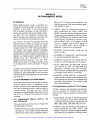
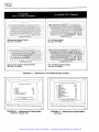
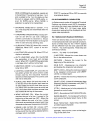
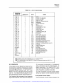
1
Artisan Technology Group is your source for quality
new and certified-used/pre-owned equipment
• FAST SHIPPING AND
DELIVERY
• TENS OF THOUSANDS OF
IN-STOCK ITEMS
• EQUIPMENT DEMOS
• HUNDREDS OF
MANUFACTURERS
SUPPORTED
• LEASING/MONTHLY
RENTALS
• ITAR CERTIFIED
SECURE ASSET SOLUTIONS
SERVICE CENTER REPAIRS
Experienced engineers and technicians on staff
at our full-service, in-house repair center
WE BUY USED EQUIPMENT
Sell your excess, underutilized, and idle used equipment
We also offer credit for buy-backs and trade-ins
www.artisantg.com/WeBuyEquipment
InstraView REMOTE INSPECTION
LOOKING FOR MORE INFORMATION?
Visit us on the web at www.artisantg.com for more
information on price quotations, drivers, technical
specifications, manuals, and documentation
SM
Remotely inspect equipment before purchasing with
our interactive website at www.instraview.com
Contact us: (888) 88-SOURCE | [email protected] | www.artisantg.com
•
ALLEN-BRADLEY
1770-805
Bulletin 1770
Industrial Terminal Systems
{Cat. No. 1770-T1, T2, T3, T4)
User's Manual
Artisan Technology Group - Quality Instrumentation ... Guaranteed | (888) 88-SOURCE | www.artisantg.com
Because of the variety of uses for this equipment and because of the differences between
this solid state equipment and electromechanical equipment, the user of and those responsible for applying this equipment must satisfy
themselves as to the acceptabilrty of each
application and use of the equipment. In no
event will Allen-Bradley Company be responsible or liable for indirect or consequential
damages resulting from the use or application
of this equipment.
The illustrations, charts and layout examples
shown in this manual are intended solely to
illustrate the text of this manual. Because of
the many variables and requirements associated with any particular installation, AllenBradley Company cannot assume responsibility or liability for actual use based upon the
illustrative uses and applications.
No patent liability is assumed by Allen-Bradley
Company with respect to use of information,
circuits, equipment or software described in
this text.
Reproduction of the content of this manual, in
whole or in part, without written permission of
the Allen-Bradley Company is prohibited.
© 1983 Allen-Bradley Company
Artisan Technology Group - Quality Instrumentation ... Guaranteed | (888) 88-SOURCE | www.artisantg.com
Page i
1770-805
TABLE OF CONTENTS
Section/
Paragraph
Title
Page
1
1.0
1.1
1.2
1.3
Introduction
1-1
Scope of Manual
1-1
General
Description ............................................................ 1-1
Compatibility'1-3
2
2.0
2.1
2.2
2.3
System Hardware
General .............................................................. .
CRT .................................................................. .
Controls .............................................................. .
Sockets and Cables ................................................... .
Keyboard Connector Cover ............................................ .
Keyboards ............................................................ .
Protective Cover ...................................................... .
2.4
2.5
2.6
3
3.0
3.1
3.2
3.3
3.4
3.5
3.6
Assembly
General .............................................................. .
Keyboard Installation .................................................. .
Keytop Overlay Installation ............................................ .
Keyboard Connector Cover Installation ................................. .
Selecting AC Input Voltage Range ...................................... .
Changing AC Fuse .................................................... .
Baud Rate, Parity and Line Frequency Selection ......................... .
2-1
2-1
2-2
2-2
2-2
2-2
2-3
3-1
3-1
3-1
3-2
3-2
3-3
3-3
Connections and Pinouts
General
Connecting a PLC-2 Family Processor .................................. .
Connecting a PLC Processor .......................................... .
Connecting a PLC-3 Processor ......................................... .
Connecting a Series 7100 CNC ......................................... .
Connecting an ASCII Terminal Using Channel B ........................ .
Connecting RS-232-C Devices to Channel 8 .......................... .
Connecting a PLC Processor for Report Generation ................... .
Connecting a PLC-3 Processor for Report Generation ................. .
Connecting Peripheral Devices to Channel C ........................... .
4-1
4-1
4-1
4-2
4-2
4-3
4-6
4-6
4-7
4-8
5.0
5.1
5.2
5.3
Mode Selection
General
Monitor Mode ..........................................................
Mode Selection with a T1, T2, or T3 System ..............................
Mode Selection with a T4 System .......................................
5-1
5-1
5-1
5-2
6
6.0
6.1
6.1.1
6.1.2
6.2
Alphanumeric Mode
General . . . . . . . . . . . . . . . . . . . . . . . . . . . . . . . . . . . . . . . . . . . . . . . . . . . . . . . . . . . . . . .
Alphanumeric Options Menus ...........................................
Alphanumeric Options (1770-T1, T2 and T3 Systems) ...................
Alphanumeric Options (1770-T4 Systems) .............................
Alphanumeric Capabilities ..............................................
6-1
6-1
6-1
6-1
6-3
4
4.0
4.1
4.2
4.3
4.4
4.5
4.5.1
4.5.2
4.5.3
4.6
5
•
•
0
•
0
•
0
•
0
•
0
•
0
•
0
•
o
•
0
•
o
•
o
•
o
•
o
•
o
•
o
•
o
•
o
•
o
•
o
•
o
0
e
0
•
•
0
•
o
~
•
G
o
•
~
.,
•
•
o
•
o
•
o
•
o
•
o
•
o
•
o
•
•
•
•
•
o
•
•
•
o
•
o
•
o
•
•
•
o
•
•
•
•
0
•
•
o
•
•
•
o
•
•
0
o
•
o
•
•
~
0
o
Artisan Technology Group - Quality Instrumentation ... Guaranteed | (888) 88-SOURCE | www.artisantg.com
o
~
•
•
•
•
•
•
•
•
•
•
•
•
Page ii
1770-805
Section/
Paragraph
6.2.1
6.2.2
6.2.3
6.2.4
Title
Alphanumeric Keyboard Definitions ................................. · ·
ASCII Control Codes .............................................. · · · ·
Graphics ......................................... · · · · · · · · · · · · · · · · · · ·
Special Control Codes . . . . . . . . ......................... · ... · · · · · · · ·
6-3
6-4
6-5
6-5
7
7.0
7.1
7.2
Troubleshooting
General .............................................................. . 7-1
7-1
Diagnostics .... ~ ~ ......... ~ ... "~.
~
Test Plug .............................................. · · · · · · · · · · · · · · · · 7-1
8
Specifications
General .............................................................. .
Physical Dimensions ................................................. .
Electrical Interface .................................................... .
Operating AC Line Voltage ........................................... .
Operating AC Voltage Range .......................................... .
Operating Line Frequency . . . . . . . ..................................... .
Fuse Rating ........................................................... .
Communication Rate .................................................. .
Environmental ........................................................ .
Functions
8.0
8.1
8.2
8.3
8.4
8.5
8.6
8.7
8.8
8.9
"$
••••••••••••••••••••••••••••••••••••
8-1
8-1
8-1
8-1
8-1
8-1
8-1
8-1
8-1
8-1
LIST OF FIGURES
Section/
Paragraph
2-1
2-2
2-3
2-4
3-1
3-2
3-3
3-4
3-5
4-1
4-2
4-3
4-4
4-5
4-6
4-7
4-8
4-9
4-10
4-11
l"itle
Industrial Terminal
Industrial Terminal Keyboard .. .
Keytop Overlays .............. .
Protective Cover .............. .
0
0
0
0
0
0
0
0
G
"
~
0
G
0
Page
0
0
0
0
0
0
0
0
0
0
0
0
0
0
0
0
0
0
0
0
0
0
0
0
0
0
0
e
0
0
0
0
0
0
0
0
e
0
0
~
~
0
"
•
•
•
•
•
..
•
•
•
•
•
•
•
•
•
•
•
•
•
•
•
•
•
•
•
•
•
•
•
•
•
•
•
•
•
a
o
o
eo
o
o
o
o
o
o
o
o
o
o
o
o
o
o
o
o
o
o
o
eo
o
o
eo
o
o
o
o
o
o
o
o
o
•
~
•
0
•
•
0
•
0
•
0
•
•
•
•
•
•
•
••
0
•
•
•
•
•
•
•
•
•
•
•
•
•
•
•
0
0
•
Attaching Keyboard Module ........................................... .
Installing Keytop Overlay .............................................. .
Attaching Keyboard Connector Cover .................................. .
AC Voltage Selection and Fuse Replacement ............................ .
Switch Group Assembly ............................................... .
PLC-2 Family Connector Diagram ...................................... .
PLC Connection Diagram ............................................. .
PLC Remote Connection Diagram ...................................... .
PLC Remote Cable Diagram ........................................... .
PLC-3 Connection Diagram ............................................ .
PLC-3 Remote Connection Diagram .................................... .
PLC-3 Remote Cable Diagram ......................................... .
Industrial Terminal/Series 7100 CNC (PI) Connection Diagram ........... .
Pinout of Channel B ................................................... .
Cable Diagram for RS-232-C and PLC Applications ...................... .
Data Handling Connection Diagram (13 feet) ............................ .
Artisan Technology Group - Quality Instrumentation ... Guaranteed | (888) 88-SOURCE | www.artisantg.com
2-1
2-3
2-4
2-3
3-1
3-1
3-2
3-2
3-3
4-1
4-2
4-3
4-3
4-4
4-4
4-5
4-5
4-6
4-7
4-7
Page iii
1770-805
Section/
Paragraph
4-12
4-13
4-14
Data Handling Connection Diagram (5,000 feet) .......................... 4-8
PLC-3 Report Generation Cable
ram ................................ 4-9
Pinout of Channel C . . . . . . . . . . . . ...................................... 4-9
5-1
5-2
5-3
Keyboard Connector Cover ............................................ . 5-1
Mode Selection Menus (T1, T2 and
5-2
Mode Selection Menus (T4) ...... .
5-3
6-1
6-2
6-3
Alphanumeric and Graphic Keytop Overlays ............................. 6-2
Alphanumeric Options Menu (1770-T1, -T2 and T3) ...................... 6-2
Graphics Example
. . . . . . . . . . . ....................................... 6-6
LIST OF TABLES
Section/
Paragraph
Title
Page
1-1
1-2
1-3
Supporting Documentation ............................................ 1-1
Industrial Terminal Systems ........................................... 1-2
Industrial Terminal/Processor Compatibility ............................. 1-3
2-1
Sockets and Cables
3-1
Switch Group Settings ................................................. 3-4
4-1
Remote Cable Parts
6-1
6-2
6-3
ASCII (American Standard Codes for Information Interchange) ........... 6-4
ASCII Control Codes . . . . . . . . . . . . . . . . . . . . . . . . . . . . . . . . . . . . . . . . . . . . . . . . . . 6-5
Industrial Terminal Control Codes ....................................... 6-6
................................................... 2-2
................................................... 4-6
Artisan Technology Group - Quality Instrumentation ... Guaranteed | (888) 88-SOURCE | www.artisantg.com
Page 1-1
1770-805
Section 1
INTRODUCTION
1.0 SCOPE OF MANUAL
The Industrial Terminal System User's Manual
describes the installation, operation, and
general capabilities of the Industrial Terminal
System (Cat. No.1770-T1, -T2, -T3, -T4). The
manual does not describe certain processor
dependent characteristics, including peripheral device operation and programming
information such as the instruction set and
report generation capability. This information
is contained in the appropriate Processor
documentation. Table 1-1 provides a cross
reference to other Allen-Bradley publications
which discuss these topics in relation to specific Allen-Bradley processors.
1.1 GENERAL
The Industrial Terminal System is a portable
and versatile programming terminal that has a
Cathode Ray Tube (CRT) and a keyboard.
When connected to an Allen-Bradley Processor, it is used to enter, monitor, and edit
ladder diagram programs and report generation messages. It can also be connected to a
line printer, a Digital Cassette Recorder, or a
Data Cartridge Recorder to perform various
peripheral functions. The Industrial Terminal
System can also be connected to a modem,
computer or other RS-232-C device for use as
a data terminal. The ladder diagram instructions and alphanumeric/ graphic characters
that are generated or received are clearly
displayed on the CRT screen.
1.2 DESCRIPTION
There are four Industrial Terminal Systems
(Cat. No. 1770-T1,T2, -T3, and -T4) available.
Each has the same types of equipment. These
items include:
~
Industrial Terminal CRT Monitor (Cat. No.
1770-TA, Series B)
TABLE 1-1- Supporting Documentation
Processor
Publication Title
Publication
Number
Programming
Information
Related Peripheral
Operating Information
PLC-3
PLC-3 Programmable Controller
Installation and Operations Manual
1775-800
PLC-3
PLC-3 Programmable Controller
Programming Manual
1775-801
X
PLC-2/30
PLC-2/30 Programmable Controller
Programming and Operations Manual
1772-806
X
X
PLC-2/20
(LP2 or LP1)
PLC-2/20 Programmable Controller
Programming and Operations Manual
1772-802
X
X
Mini-PLC-2/15
MINI-PLC-2/15 Programmable Controller
Programming and Operations Manual
1772-804
X
X
Mini-PLC-2 Programmable Controller
Programming and Operations Manual
1772-821
X
X
PLC-2 User's Manual
1772-800
X
X
PLC Programmable Controller
Programming and Operations
1774-800
X
PLC Programmable Controller Program
Panel Interface Module Operating
Instructions
1774-817
X
Programmable Interface User's Guide
7100-4.2
X
Mini-PLC-2
PLC-2
PLC
PLC
D
0
Series 7100
D
X
X
Only 1770-T2 and 1770-T3, series 8 or later Industrial Terminal Systems can be used with a PLC Programmable controller. They are used in
the same manner as the PLC Program Panel, except that a blank blue key is used instead of a SELECT key.
Artisan Technology Group - Quality Instrumentation ... Guaranteed | (888) 88-SOURCE | www.artisantg.com
Page 1-2
1770-805
• Keyboard Connector Cover (Cat. No.
1770-XB)
• CRT Troubleshooting Test Plug (Cat. No.
1774-TT)
• User's Manual (Publication 1770-805)
• Keyboard with one or more Keytop Overlays
• One or more cables
The first four items listed above are the same
for all Industrial Terminal Systems. The last
two items listed are specific to each Industrial
Terminal System. The Keyboard, Keytop Over-
lays, and Cables shipped with each Industrial
Terminal System are listed in Table 1-2.
Note that the PLC-2 Family Keyboard (Cat.
No. 1770-FD) and the PLC-3 Keyboard (Cat.
No. 1770-FE) have a projection on the back
that fits into the Industrial Terminal CRT
Monitor. This projection is designed to fit into
a notch on a Series B Industrial Terminal CRT
Monitor. Series A Industrial Terminal CRT
Monitors, shipped with earlier 1770-T1 and
-T2 systems, do not have a notch. Thus, 1770FD and 1770-FE Keyboards can only be used
with Series B Industrial Terminal CRT
Monitors.
TABLE 1-2- Industrial Terminal Systems
Industrial Terminal
System (Cat. No.) 0
1770-T1
Keyboard
Modules
PLC-2 Keyboard
(Cat. No. 1770-FC
Keytop Overlays
PLC-2 Keytop Overlay
(Cat. No. 1770-KCA)
Cables
PLC-2 Program Panel
Interconnect Cable
(Cat. No. 1772-TC)
Alphanumeric Keytop
Overlay (Cat. No. 1770KAA)
1770-T2
PLC/PLC-2 Keyboard
(Cat. No. 1770-FA)
PLC Keytop Overlay
(Cat. No. 1770-KBA)
PLC-2 Keytop Overlay
(Cat. No. 1770-KCA)
Alphanumeric Keytop
Overlay (Cat. No. 1770KAA)
1770-T3
PLC-2 Family Keyboard
(Cat. No. 1770-FD)
PLC-2 Family Keytop
Overlay (Cat. No. 1770KCB)
PLC Program Panel
Interconnect Cable
PLC-2 Program Panel
Interconnect Cable
(Cat. No. 1772-TC)
PLC-2 Program Panel
Interconnect Cable
(Cat. No. 1772-TC)
Alphanumeric Keytop
Overlay (Cat. No. 1770KAA)
1770-T 4
0
PLC-3 Keyboard
(Cat. No. 1770-FE)
PLC Keytop Overlay
(Cat. No. 1770-KBA
PLC Program Panel
Interconnect Cable
(Cat. No. 1774-TC)
PLC-3 Keytop Overlay
(Cat. No. 1770-KDA)
PLC-3 Industrial
Terminal Cable
(Cat. No. 1775-CAT)
All Industrial Terminal Systems are shipped with the following common equipment:
Industrial Terminal (Cat. No. 1770-TA. Series B)
Keyboard Connector Cover (Cat. No. 1770-XB)
CRT Troubleshooting Test Plug (Cat. No. 1774-TT)
User's Manual (Publication 1770-805)
Artisan Technology Group - Quality Instrumentation ... Guaranteed | (888) 88-SOURCE | www.artisantg.com
Page 1-3
1770-805
In addition to the standard equipment shipped
with the 1770-T1, -T2, - T3, andT4 systems,
optional equipment can be ordered. These
system options include:
1.3 COMPATIBILITY
The compatibility chart in Table 1-3 summarizes which Industrial Terminal Systems
can be used with which Processors. For
example, the 1770-T1, - T2, and T3 Industrial
Terminal Systems can be used with all PLC-2
Family Processors. The 1770-T3 Industrial
Terminal System, however, is the only one
that can fully support the PLC-2/20 (LP2),
PLC-2/30 and Mini-PLC-2/15 Processors.
Therefore, programs entered on these Processors using a 1770-T3 Industrial Terminal
System must not be edited using either 1770T1 or -T2 Industrial Terminal Systems. The
limitations footnoted in Table 1-3 are described
in the corresponding programming manuals
the Processors.
• Keyboard Storage Case (Cat. No. 1770-XC)
• Industrial Terminal Adapter Cable (Cat. No.
1770-CB, -CC)
• Alphanumeric/ Graphics Keytop Overlay
(Cat. No. 1770-KAB)
• PLC-3 Graphics Keytop Overlay (Cat. No.
1770-KDB)
TABLE 1-3- Industrial Terminal/Processor Compatibility
Industrial Terminal
System (Cat. No.)
PLC
PLC-2
(LB)
Mini-PLC-2
PLC-2/20
(LN1 ,LN2,LN3)
(LP1)
PLC-2-20
(LP2)
X
X
X
X
1770-T2
X
X
X
X
X
1770-T3
XI:J
X
X
X
1770-T1
D
D
X
Mini-PLC-2/15
(LV)
X
X
D
D
X
PLC-2/30
(LP3)
X
X
PLC-3
D
D
X
X
X
1770-T4
D Processor capabilities will be limited when using this Industrial Terminal.
1:1 1770-T3 series B or later systems are compatible with PLC Programmable Controllers. Earlier 1770-T3 systems are not
compatible with PLC Programmable Controllers.
Artisan Technology Group - Quality Instrumentation ... Guaranteed | (888) 88-SOURCE | www.artisantg.com
Series 7100
CNC
X
X
Page 2-1
1770-805
Section 2
SYSTEM HARDWARE
2.0 GENERAL
(Figure 2-1). The screen can display 80
characters across by 24 lines down. When
used for ladder diagram programming, the
bottom three lines are reserved for displaying
prompts and other related information. The
processor and the type of instruction (single,
multiple word, or block) determine the number of rungs or rung branches and the number
of elements per rung displayed on the screen.
All models of the Industrial Terminal System
have the same types of hardware components.
This section describes these components.
2.1 CRT
The Industrial Terminal System has a nineinch diagonal CRT used as the display screen
21.~
:UU: . I
'
Power
On/Off Switch
Sealed Touchpad
with Keytop
Overlay
~--Keyboard
Keyboard Locking
Lever
Front View
r.
~.Jib II I. !U
J .J itt!llli t .....
I'
Fuse and AC Voltage
Selection Board
Channel _ _ __
Sockets
AC Power Cord
Connection
Video Output Jack
Rear View
FIGURE 2-1 -
Industrial Terminal
Artisan Technology Group - Quality Instrumentation ... Guaranteed | (888) 88-SOURCE | www.artisantg.com
Page 2-2
1770-805
When used as a data terminal or for report
generation, the full80 x 24 screen can be used
to display alphanumeric and graphic characters.
2.2 CONTROLS
There are three controls on the Industrial
Terminal CRT Monitor as Figure 2-1 shows.
They are:
• Power ON/OFF -located on the front of the
Industrial Terminal CRT Monitor. When the
power switch is ON, it engages a mechanical
interlock to guard against attaching or removing the keyboard while power is applied.
• Brightness - located on the back of the
Industrial Terminal CRT Monitor. It controls the intensity of the screen.
• Volume- located on the back of the Industrial Terminal CRT Monitor. It controls the
audio level of the beep tone that is generated
when a valid key on the keyboard is pressed.
2.3 SOCKETS AND CABLES
The various sockets on the back of the Industrial Terminal CRT Monitor (Figure 2-1) include the:
• AC power cord connection
• Three Channel sockets (A, B, and C)
• Video Output Jack
Channels A, B, and Care the communication
ports for connecting Processors, peripheral
devices, computers, and modems. Channel B
performs different functions in different Industrial Terminal Systems (Table 2-1 ). The Video
Output Jack can be used to connect an RS170 compatible Black & White CRT monitor
capable of underscan operation. The function
of each channel and the cables required are
described in Table 2-1.
2.4 KEYBOARD CONNECTOR COVER
The Industrial Terminal System is shipped
with the keyboard connector cover installed
on the front of the CRT Monitor. If the Industrial Terminal System is used as a monitor
(without a keyboard), this keyboard connector
cover MUST be installed.
2.5 KEYBOARDS
There are four keyboards available, one for
each Industrial Terminal System. They are:
TABLE 2-1 -Sockets and Cables
Function
Socket
Industrial Terminal
System
Cables
Channel A
PLC-2 Family
Connects to a PLC-2
Family Processor or a
Series 7100 CNC
1770-T1 ,-T2,-T3
1772-TC
Channel B
PLC-3/PLC
Data Terminal
Connects to a PLC
Processor
1770-T2
1770-T3 series B
1774-TC
1770-CB D with a
1774-DC or DC2 D
Connects to a PLC-3
Processor
1770-T4
1775-CAT
Use as a Data Terminal
or Monitor
All
1770-CB D (male) or
1770-CC D (female)
ChanneiC
Peripheral
Connecting to a Digital
Cassette Recorder Data
Cartridge Recorder or hard
copy printer
All
Device provided
RS-232-C
Video Output Jack
(BNC) 75
Connecting to a B & W
CRT Monitor f)
All
User provided
RS-170
D Optional Cable. Must be ordered separately.
f) Must be Black & White monitor with underscan operation (the raster must be fully contained within the viewing area of
the screen).
Artisan Technology Group - Quality Instrumentation ... Guaranteed | (888) 88-SOURCE | www.artisantg.com
Page 2-3
1770-805
• The 1770-FC Keyboard for a 1770-T1 system
• The 1770-FD Keyboard for a 1770-T3 system
sors. Both the keytop overlays that are shipped
with each Industrial Terminal System and the
optional keytop overlays are identified in
Figure 2-3.
• The 1770-FE Keyboard for a 1770-T 4 system
2.6 PROTECTIVE COVER
Each keyboard is shipped with one or more
keytop overlays. The keyboard (Figure 2-2)
has a sealed touch pad and contains the PROM
memory that gives the keyboard its instruction set for programming the specific Proces-
When the Industrial Terminal System is not in
use, the Protective Cover (Figure 2-4) should
be installed to protect the CRT screen and the
keyboard. It can also be used to store unused
equipment such as the CRT Troubleshooting
Test Plug, extra keytop overlays, and cables.
• The 1770-FA Keyboard for a 1770-T2 system
FIGURE 2-4- Protective Cover
FIGURE 2-2- Industrial Terminal Keyboard
Artisan Technology Group - Quality Instrumentation ... Guaranteed | (888) 88-SOURCE | www.artisantg.com
Page 2-4
1770-805
STANDARD
o
§JOOOOOODDDDDDD
GBBBBBEJBCDOliJOOOO
BBBBEJBBEJITJO@J[]J[]J
()
§JOOOOOOOOOOODD
BBBBBBBEJBCDliJOO[[]
BBBBEJBBBEJ@fiJ[]J[]J
O§JOJCOBBBBBBBGJ~@J
OEJEJEJBBBBBBBl:!J@~
O§JCIJCOBBBBBBOGJ~W
O~EJEJEJBDBBBOO@O
,;,;,.....=
PLC-2 Keytop Overlay 0 f)
PLC Keytop Overlay f) g
PLC-2 Family Keytop Overlay
r!J
PLC-3 Keytop Overlay 9
r::lf'll""ll#lisll%lislGJf'lf'lr:::lf*ll=l0
~L!JllJLlJ~~~ 7 ~L!JL!J~L=J
EJ[ijfil@@@@@@@ffi@JEJ0°
ooonnnnnmf"'lr+lr:lwO
L:J[IJ(IJ[QJ[D[g][HJ[IJ[K]ITJ[IJ~~
OEJrnrnEatil@ffiffiEBEBEB§O
oooooooooooooo
D
Part of a 1770-T1 System
6
Part of a 1770-T2 System
BJ
Part of a 1770-T3 System
9
Part of a 1770-T4 System
"""""'"""""'"'
Alphanumeric Keytop Overlay 0 f) D
OPTIONAL
u
©--· '"'"""'""" """"
j© .. "'""""""
Alphanumeric/Graphics Keytop Overlay D
DAn Option for the 1770-T1, -T2 and -T3 Systems
PLC-3 Graphics Keytop Overlay 6
6
An Option for the 1770-T 4 Systems Only
FIGURE 2-3- Keytop Overlays
Artisan Technology Group - Quality Instrumentation ... Guaranteed | (888) 88-SOURCE | www.artisantg.com
0
Page 3-1
1770-805
Section 3
ASSEMBLY
3.0 GENERAL
Before any Industrial Terminal System can be
used, it must be set up for proper operation.
This includes selecting the correct input
voltage, line frequency, and fuse, and setting
the correct baud rate and parity for Channels
Band C.
Since all Industrial Terminal Systems are set
up in the same manner, the information in this
section applies to all systems.
3.1 KEYBOARD INSTALLATION
- - - _ Bushings/
Perform the following steps to attach the
keyboard to the Industrial terminal:
1. Loosen the mounting screws on the keyboard connector cover and remove the connector cover.
2. Be sure the power switch is off.
3. Lift and move the locking lever to the
UNLOCK position.
4. Align the two support pins on the keyboard
with the bushings on the front of the chassis
(Figure 3-1) and insert the keyboard.
5. Lift and move the locking lever to the LOCK
position.
Keyboard Locking Lever
FIGURE 3-1 -Attaching Keyboard Module
Note that the PLC-2 Family Keyboard (Cat.
No. 1770-FD) and the PLC-3 Keyboard (Cat.
No. 1770-FE) have a projection on the back
that fits into the Industrial Terminal CRT
Monitor. This projection is designed to fit into
a notch on a Series 8 Industrial Terminal
Monitor. Series A Industrial Terminal Monitors, shipped with earlier 1770-T1 and -T2
systems, do not have a notch. Thus, 1770-FD
and 1770-FE Keyboards can only be used with
Series 8 Industrial Terminal Monitors.
3.2 KEYTOP OVERLAY INSTALLATION
The desired keytop overlay is easily installed
on the keyboard by aligning the notches in the
overlay with the tabs on the keyboard as
Figure 3-2 shows.
Mounting
Notch
Keytop Overlay
Mounting
Tab
FIGURE 3-2- Installing Keytop Overlay
Artisan Technology Group - Quality Instrumentation ... Guaranteed | (888) 88-SOURCE | www.artisantg.com
Page 3-2
1770-805
3.3 KEYBOARD CONNECTOR COVER
INSTALLATION
If the Industrial Terminal System is used as a
monitor (without a keyboard), the keyboard
connector cover MUST be installed. When
attaching the keyboard connector cover,
tighten the two mounting screws (Figure 3-3)
by hand; do not overtighten.
Wire
Loop
3.4SELECTING AC INPUT VOLTAGE RANGE
All Industrial Terminal CRT Monitors are
shipped configured for 120V AC, 60 Hz
operation.
The CRT Monitor can be configured for
220/240V AC operation by repositioning the
AC selector board, located on the back of the
Industrial Terminal CRT Monitor (Figure 3-4).
The board has four positions: 100, 120, 220
and 240. When either 100 or 120 is selected,
the voltage range is 98 to 132V AC. When 220
or 240 is selected, the voltage range is 196 to
250V AC.
When the Industrial Terminal System is set up
for 220/240V AC operation, place the 230V
AC Selection
Board
Plastic
Slide Cover
Fuse
Fuse Pull
Lever
Mounting
Screws
..., / . /
\
Keyboard Connector Cover
FIGURE 3-3- Attaching Keyboard Connector
Cover
Label Here
FIGURE 3-4- AC Voltage Selection and Fuse
Replacement
Artisan Technology Group - Quality Instrumentation ... Guaranteed | (888) 88-SOURCE | www.artisantg.com
Page 3-3
1770-805
label, contained in the 230V Fuse Kit, directly
below the AC selection board housing (Figure
3-4). Also replace the 1 amp fuse with the 1/2
amp fuse (Section 3.5), and attach a 240V
cord.
4. Move the FUSE PULL lever back to the right.
Perform the following steps to change the AC
input voltage setting (Refer to Figure 3-4):
6. Attach a suitable power cord to the Industrial Terminal CRT Monitor.The power cord
supplied with the unit is suitable for 120VAC
operation. For 220/240V operation, the cord
must be replaced or modified by replacing the
plug.
1. Be sure the power ON/OFF switch is turned
OFF and the AC power cord is disconnected
from the Industrial Terminal CRT Monitor.
2. Slide the plastic cover to the left over the AC
power cord connection.
3. Insert a piece of wire through the hole on
the AC selection board and twist the ends
together to form a loop.
4. Grasp the wire loop with a pair of needle
nose pliers and pull to remove the board.
5. Remove the wire loop from the AC selection
board.
6. Position the AC selection board so that the
number that is visible matches the line voltage.
7. Install the AC selection board. The number
now visible should match the line voltage.
8. If the 220/240V setting is used, place the
230V label below the selection board.
5. Insert the proper fuse: 1 amp for 120V
operations and 1/2 amp for 220/240V operations.
3.6 BAUD RATE, PARITY AND LINE FREQUENCY SELECTION
Located on the front of the main logic board of
the CRT monitor is a set of switches in a
switch group assembly (Figure 3-5). They
select line frequency, and the baud rate and
parity used in Channels B and C of the
Industrial Terminal CRT Monitor.
Table 3-1 shows the proper switch positions
for selecting line frequency, baud rate, and
parity.
Note that with a 1770-T3 system (with a
keyboard attached), switches 4 and 5 can be
used to select automatic report generation
and turn ON Channel C during power up and
Mode Select in addition to selecting parity.
9. Change the AC fuse and power cable as
described below.
3.5 CHANGING AC FUSE
Perform the following steps to change or
inspect the main AC fuse of the Industrial
Terminal CRT Monitor (Figure 3-4):
1. With the power switch OFF, disconnect the
AC power cord from the Industrial Terminal
CRT Monitor.
2. Slide the plastic cover to the left over the AC
power cord connection.
3. Pull the FUSE PULL lever to the left and
remove the fuse.
Baud Rate, Parity and Line
Frequency Switches
FIGURE 3-5 - Switch Group Assembly
Artisan Technology Group - Quality Instrumentation ... Guaranteed | (888) 88-SOURCE | www.artisantg.com
Page 3-4
1770-805
TABLE 3-1 -Switch Group Settings
SWITCH
SWITCH
SWITCH
Hz
SPEED
TYPE
NONE 0
ODD
EVEN
NOT
USED fJ
LINE FREQ. (Hz)
BAUD RATE
PARITY
4
5
DOWN
DOWN
UP
DOWN
UP
DOWN
UP
UP
0
1
2
3
110
300
600
1200
2400
4800
9600
DOWN
DOWN
DOWN
DOWN
UP
UP
UP
DOWN
DOWN
UP
UP
DOWN
DOWN
UP
DOWN
UP
DOWN
UP
DOWN
UP
DOWN
NOT
USED
UP
UP
UP
6
50
60
DOWN
UP
When connecting to a PLC Processor, this switch setting must be used.
fJ With a 1770-T3 system, this setting can be used for Automatic Report Generation at
power-up. With a 1770-T4, Series B or later, this setting selects PLC-3 mode at
power-up if a PLC-3 processor is connected.
Artisan Technology Group - Quality Instrumentation ... Guaranteed | (888) 88-SOURCE | www.artisantg.com
Page 4-1
1770-805
Section 4
CONNECTIONS AND PINOUTS
4.0 GENERAL
nected from the PLC-2 Family Processor
without removing AC power.
The connection diagrams in this section show
how to connect Allen-Bradley Processors, the
Series 7100 CNC, peripheral devices, modems,
and computers to Channels A, B, and C of an
Industrial Terminal System.
4.2 CONNECTING A PLC PROCESSOR
Note: Before making any connections, be sure
both Industrial Terminal System parity switches (4 and 5) are set to the DOWN position.
4.1 CONNECTING A PLC-2 FAMILY PROCESSOR
The PLC Processor can be connected up to 15
cable-feet from a 1770-T2 or 1770-T3, series B
Industrial Terminal System using the Program
Panel Interconnect Cable (Cat. No. 1774-TC).
The PLC Processor must have either a Program Panel interface Module (Cat. NO. 1774TB,-TB2) or an On-line Programming Module
(Cat. No.1774-TL2) installed inslotzeroofits
chassis. The 41-pin end of the cable connects
to the module in slot zero of the PLC Processor
chassis (Figure 4-2). The other end of the
cable (25-pin end) is connected to Channel B.
The cable can be connected or disconnected
All PLC-2 Family Processors connect to
Channel A of a 1770-T1,T2, or -T3 Industrial
Terminal System in the same manner and with
the same cable (Figure 4-1 ). One end of the
Program Panel Interconnect Cable (Cat. No.
1772-TC) is connected to Channel A of the
Industrial Terminal System. The other end is
connected to a 15-pin socket on the front of a
PLC-2 family Processor. The socket on the
Processor will be labeled either INTERFACE
or PROGRAM PANEL. The Industrial Terminal System can be connected to and discon-
PLC-2 Family
Processor
e
o
Ls
o
PLC
if!/30
1770-T1, T2, or T3
Industrial Terminal
PROGRAMMABLE
CONTROLLER
X~.
15-Pin Socket
~Labeled Interface
::::_Bj
.---"-----::r···=::~=·.~y
0
I\\
or Program Panel
-
~.
•
<
E
:.,c, . ,,...,,,J..
D<AG .. OSTICS
---·
--
10 Feet
\
Program Panel Interconnect Cable
(Cat. No. 1772-TC)
10055
FIGURE 4-1 -
PLC-2 Family Connection Diagram
Artisan Technology Group - Quality Instrumentation ... Guaranteed | (888) 88-SOURCE | www.artisantg.com
Page 4-2
1770-805
PLC Processor
c
@
@
('!J
@
@
@
Program Panel
Interface Module
or On-Line
~Programming
§
©
.
~
[
(e
AI,LEN-BHADLEY
Module
IJ
l=Jl .
0
1770-T2 or 1770-T3. series B
Industrial Terminal
Q/
/0 I 10
II
\--1'
~
~
"0
c:::;Q] 0-
R r=J r=JGJI
-~ /o
I
•I ~~ ~
Channel
15 Feet
'
\I._
B
.)
~
Program Panel Interconnect Cable
(Cat No. 1774-TC)
10056
FIGURE 4-2- PLC Connection Diagram
without removing AC power from either the
Industrial Terminal System or the PLC Processor.
The 1770-T2 or 1770-T3, series B Industrial
Terminal System can be connected up to 5000
cable-feet from the PLC Processor by using
additional cable between the 1774-TC Cable
and Channel B (Figure 4-3). This additional
cable (Cat. No. 1778-CR, Belden 8723 or its
equivalent) must be constructed as shown in
Figure 4-4. The parts required to construct
this cable are listed in Table 4-1.
4.3 CONNECTING A PLC-3 PROCESSOR
The PLC-3 Processor is connected to the
1770-T4 Industrial Terminal System for programming using the PLC-31ndustrial Terminal
Cable (Cat. No. 1775-CAT). The end of the
cable labeled INDUSTRIAL TERMINAL END
connects to Channel B (Figure 4-5). The end
of the cable labeled PLC-3 END is connected
to one of two ports on the PLC-3 Processor:
either Channel 0 on the front panel or Channel
5 on the 1/0 Scanner-Programmer Interface
Module (Cat. No. 1775-S4A) inside the PLC-3
Chassis.
The 1770-T4 Industrial Terminal System can
be connected up to 5000 cable feet from the
PLC-3 Processor (Figure 4-6) using cable
constructed from Cat. No. 1778-CK, Belden
8723 or its equivalent. The cable diagram in
Figure 4-7 shows how to wire the pins to the
male connectors. The parts necessary to construct the cable are listed in Table 4-1.
4.4 CONNECTING A SERIES 7100 CNC
The Programmable Interface (PI) Module is
an optional software feature of the Series 7100
Computerized Numerical Control (CNC). It
consists of a printed circuit module that can
be programmed much like a programmable
controller, using ladder-diagram instructions.
For detailed information about programming
and operating the Series 7100 CNC with the PI
Module, refer to Programmable Interface
User's Guide (Publication 7100-4.2).
The 1770-T1, -T2, and -T31ndustrial Terminal
Systems can be connected to the PI Module
using the 1772-TC Program Panel Interconnect Cable (Figure 4-8). One end of the cable
connects to Channel A on the Industrial Terminal System. The other end connects to the
15-pin socket on the front edge of the PI
Module. Power need not be removed when
Artisan Technology Group - Quality Instrumentation ... Guaranteed | (888) 88-SOURCE | www.artisantg.com
Page 4-3
1770-805
Program Panel
Interface Module
1770-T2 or 1770-T3, series B
Industrial Terminal
PLC Processor
c
@
@
@
@
@
@
(
"
@
§
ALLEN-BRADLEY
I~
l
0
Up to 5000 Feet
Channel B
Cat. No. 1778-CR,
Belden 8723, or Equivalent
Program Panel Interconnect Cable
(Cat. No. 1774-TC)
10057
FIGURE 4-3- PLC Remote Connection Diagram
Channel B
Cat. No. 1778-CR
or Belden 8723
Program Panel
Interconnect Cable
i
Female Connector
Male Connector
10058
FIGURE 4-4- PLC Remote Cable Diagram
connecting and disconnecting the Industrial
Terminal System.
4.5 CONNECTING AS AN ASCII TERMINAL
USING CHANNEL B
The Industrial Terminal System can operate
as a data terminal in Alphanumeric mode. As a
data terminal, it communicates with RS-232-C
devices such as modems and computers. It
also performs report generation with the PLC
and PLC-3 Processors. Cable connections for
all of these functions are made to Channel B
as described in the following sections.
Artisan Technology Group - Quality Instrumentation ... Guaranteed | (888) 88-SOURCE | www.artisantg.com
Page 4-4
1770-805
PLC-3 Processor
Programming:
Front Panel or
1775-84A Module
Report Generation:
1775-848 Module
1770-T4
Industrial Terminal
Channel B
15 Feet
PLC-3 Industrial Terminal Cable
(Cat. No. 1775-CAT.)
10059
FIGURE 4-5 -
PLC-3 Connection Diagram
PLC-3 Processor
Programming:
Front Panel or
1775-84A Module
Report Generation:
1775-848 Module
1770-T4
Industrial Terminal
0_,<.------i
Channel B
Up to 5000 Cable Feet
Cat. No. 1778-CR,
Belden 8723, or equivalent
10060
FIGURE 4-6- PLC-3 Remote Connection Diagram
Artisan Technology Group - Quality Instrumentation ... Guaranteed | (888) 88-SOURCE | www.artisantg.com
Page 4-5
1770-805
PLC-3 Processor
Channel 0 - Front Panel
or
Channel 5 - S4A or S4B Module
Channel B
Male Connector
Male Connector
10061
FIGURE 4-7- PLC-3 Remote Cable Diagram
Series 7100 CNC
1770-T1, T2 or T3
Industrial Terminal
PI Module
Channel A
Program Panel Interconnect Cable
(Cat. No. 1772-TC)
10062
FIGURE 4-8 -Industrial Terminal/Series 7100 CNC (PI) Connection Diagram
Artisan Technology Group - Quality Instrumentation ... Guaranteed | (888) 88-SOURCE | www.artisantg.com
Page 4-6
1770-805
TABLE 4-1 -
MANUFACTURER'S
DESTINATION
PART
25-Pin Female Connector
Cannon Type DB-25S, or
equivalent
25-Pin Male Connector
Cannon Type DB-25P, or
equivalent
Plastic Hood
AMP Type 205718-1
2 twisted pair 22 guage,
individually shielded cable
Cat. No. 1778-CR
Belden 8723, or equivalent
Cannon
666 E. Dyer
Santa Ana,
CA 92702
Amp, Inc.
P.O. Box 3608
Harrisburg,
PA 17105
1
Transmitted-- 2
Data
Pins
I
18
20
Belden Corp.
P.O. Box 1327
Richmond,
IN 47374
identifies the pins used. The cable to be used
is Cat. No. 1778-CR, Belden 8723 or its equivalent and is constructed as shown in Figure
4-10. The parts for constructing this cable are
listed in Table 4-1. Note that pins 7, 18, and 25
on the Industrial Terminal CRT Monitor end of
the cable must be wired together.
Channel B
Protective ~
Ground
Remote Cable Parts
Received
Data
Return
Data
Terminal
/Ready
Transmitted
25~Data
Return
For RS-232-C applications that require distances greater than 50 feet, refer to the EIA
RS-232-C Standards publication for guidelines.
10063
FIGURE 4-9 -
Pinout of Channel B
4.5.1 Connecting RS-232-C Devices to ChannelS
Modems, computers, or other non-AllenBradley RS-232-C devices can be connected
to Channel B using one of two cables. These
cables are three feet long and differ only by
the type of connectors. They are:
• Industrial Terminal/Data Handling Adapter
Cable (Cat. No. 1770-CB) - has two male
connectors
• Industrial Terminal Adapter Cable (Cat. No.
1770-CC) - has one male and one female
connector
Cable can be constructed for distances up to
50 feet. The pinout of Channel B (Figure 4-9)
4.5.2 Connecting a PLC Processor for Report
Generation
The Industrial Terminal System, in Alphanumeric mode, can be used for report generation with a PLC Processor. The Industrial
Terminal System can be connected locally (13
cable-feet) or up to 5000 cable feet from the
PLC Processor.
The local configuration (Figure 4-11) shows a
Series B or later Data Handling Module (Cat.
No. 1774-DH2) in the PLC Processor Chassis.
The ten foot Data Handling Interconnect Cable
(Cat. No. 1774-DC2) connects this Module to
one end of the 1770-CB Cable. The other end
of the 1770-CB Cable connects to Channel B.
The 5000 cable-foot configuration (Figure 412) uses the same Data Handling Module and
cable, and a section of constructed cable (Cat.
No. 1778-CR, Belden 8723 or equivalent). The
Artisan Technology Group - Quality Instrumentation ... Guaranteed | (888) 88-SOURCE | www.artisantg.com
Page 4-7
1770-805
Cat. No. 1778-CR,
Belden 8723 or Equivalent
\
Cat. No. 1778-CR,
Belden 8723 or
Equivalent
To Channel B
10064
FIGURE 4-10- Cable Diagram for RS-232-C
PLC Processor
0
@
@
@
@
@
@
©
(
•
1774-DH2
Data Handling
IJ/Module, Series
8 or Later
Industrial
Terminal
/1
0
§
ALLEN-BRADLEY
c=J )
0
0
Channel 8
10 Feet
Data Handling Interconnect Cable
(Cat. No. 1774-DC2)
Industrial Terminal/ Data Handling
Adapter Cable
(Cat. No. 1770-CB)
10065
L---------------------·~·-·-------------------.....1
FIGURE 4-11 -Data Handling Connection Diagram (13 feet)
cable is constructed as shown in Figure 4-13
using two male connectors. The parts needed
to construct the cable are listed in Table 4-1.
4.5.3 Connecting a PLC-3 Processor for
Report Generation
The Industrial Terminal System can be used in
Alphanumeric mode for report generation
with the PLC-3 Processor. They can be connected locally (15 cable-feet) or up to 5000
cable-feet apart.
The PLC-3 Processor is connected locally to
the Industrial Terminal System for report
Artisan Technology Group - Quality Instrumentation ... Guaranteed | (888) 88-SOURCE | www.artisantg.com
Page 4-8
1770-805
Industrial
Terminal
PLC Processor
@
@
0
@
©
(
-
0~------i
@
@
D1
@
§
ALLEN-BRADLEY
r==J )
O
0
Channel 8
Up to 5000 Feet
Data Handling Interconnect Cable
(Cat. No. 1774-DC2)
Cat. No. 1778-CR, Belden
8723 or Equivalent
10066
FIGURE 4-12- Data Handling Connection Diagram (5000 feet)
generation using the PLC-3 Industrial Terminal Cable (Cat. No. 1775-CAT) as shown in
Figure 4-5. One end connects to ChannelS on
the 1/0 Scanner-Message Handling Module
(Cat. No. 1775-S4B) inside the PLC-3 Processor Chassis. The other end connects to
Channel Bon the Industrial Terminal System.
To connect the PLC-3 Processor up to 5000
feet from the Industrial Terminal System for
report generation (Figure 4-6), a cable with
two male connectors must be constructed
using Cat. No. 1778-CR, Belden 8723 or equi-·
valent following the cable diagram in Figure
4-7. The parts required to build this cable are
listed in Table 4-1.
4.6 CONNECTING PERIPHERAL DEVICES
TO CHANNEL C
RS-232-C peripheral devices such as the Digital Cassette Recorder (Cat. No. 1770-SA), the
Data Cartridge Recorder (Cat. No. 1770-SB),
or a hard copy printer can be connected to
Channel C of any Industrial Terminal System.
The pinout of Channel C (Figure 4-14) shows
the pins used for making cable for this
channel.
Artisan Technology Group - Quality Instrumentation ... Guaranteed | (888) 88-SOURCE | www.artisantg.com
Page 4-9
1770-805
Data Handling Cable
(Cat. No. 1774-DC2)
To Channel B
Cat. No. 1778-CR
Belden 8723 or
equivalent
~----------l_-----+~r-r---~
Note: Remove the jumper in the Data Handling Cable (Cat. No. 1774-DC2)
10067
FIGURE 4-13- PLC Remote Report Generation Cable Diagram
Channel C
Protective
Ground
!Received
Data
2
3
Transmitted /
Data
/6
Data Set
Ready
/ j/ j
1
Signal /
Ground
j
/
Carrier
Detect
10068
FIGURE 4-14- Pinout of Channel C
Artisan Technology Group - Quality Instrumentation ... Guaranteed | (888) 88-SOURCE | www.artisantg.com
Page 5-1
1770-805
Section 5
MODE SEL,ECTION
5.0 GENERAL
All Industrial Terminal Systems can operate in
an Alphanumeric mode and one or more
Processor modes. In addition, all Industrial
Terminal Systems can operate in a Monitor
mode when the keyboard is replaced by a
keyboard connector cover.
When the Industrial Terminal System is turned
ON, self-diagnostic checks are performed.
When no problems are found and a keyboard
is attached, either a Processor mode or Alphanumeric mode can be selected. The 1770-T4
Industrial Terminal System allows either automatic or manual mode selection after faultfree diagnostics are performed at power up.
Mode selection with 1770-T1, -T2, and T3
Industrial Terminal Systems is performed
manually.
If a problem is detected during power up of
any Industrial Terminal System, a diagnostic
fault prompt and continuous beep tone are
generated.
5.1 MONITOR MODE
on the keyboard is pressed, a MODE SELECTION menu will be displayed on the screen.
This menu identifies the keyboard that is
attached and lists the operating modes and
keytop overlays that can be used (Figure 5-2).
Note that the 1770-T3 Mode Selection menu
identifies the Processor connected to Channel A by intensifying its name on the screen.
To select the desired mode, install the proper
keytop overlay and enter the appropriate twodigit number.
When a Processor mode is selected, the Industrial Terminal System is used to enter, edit,
and monitor ladder diagram instructions. In
addition, report generation for PLC-2 family
Processors is performed in this mode. Information on the instruction set and report
generation for the various Processors is found
in the appropriate Processor documentation.
When Alphanumeric mode is selected, the
Industrial Terminal System is used as a data
terminal. ASCII code can be transmitted to or
from a modem, computer or other RS-232-C
device using Channel B. Report generation
tor PLC Processors is also performed in this
When the keyboard connector cover is attached and fault-free diagnostics have been
performed, the Industrial Terminal System
automatically enters the Monitor mode. In this
mode, the Industrial Terminal System functions as a data terminal that can only receive
ASCII characters through Channel B. If lower
case ASCII characters are received, their
upper case equivalents will be displayed.
The baud rate and parity switch settings for
the Industrial Terminal System (Section 3.6)
must match the baud rate and parity of the
data received on Channel B.
5.2 MODE SELECTION WITH A T1, T2, OR T3
SYSTEM
The operating modes for the 1770-T1, - T2,
and - T3 systems are selected in the same
manner from a mode selection menu. After
fault-free diagnostics have been performed at
power up, or when the [MODE SELECT] key
Keyboard Connector Cover
(Cat. No. 1770-XB)
FIGURE 5-1- Keyboard Connector Cover
Artisan Technology Group - Quality Instrumentation ... Guaranteed | (888) 88-SOURCE | www.artisantg.com
Page 5-2
1770-805
that can be selected before beginning alphanumeric operations. The Alphanumeric mode
operating commands for all Industrial Terminal Systems are fully described in Section 6.
MODE SELECTION
KEYBOARD MODULE 1770~FCC SERIES AiD
5.3 MODE SELECTION WITH A T4 SYSTEM
INSERT
KEYTOP OVERLAY
11
12
A 1770-T4 Industrial Terminal System provides automatic mode selection at power-up.
Series A, Rev B and later systems first determine the setting of the parity switches. If the
switches are set for ODD, EVEN, or NONE, the
Industrial Terminal System immediately enters
the Alphanumeric Mode. The baud rate, parity,
and line frequency are determined by the
switch group settings on the Industrial Terminal System. If the switches are in the NOT
USED position (both up), the Industrial Terminal System tries to communicate with a
PLC-3 Processor. It sends a message out
Channel B three times at each baud rate
starting at 9600. While attempting to communicate with a PLC-3 Processor, it displays a
prompt on the screen. If a PLC-3 Processor is
connected, the Industrial Terminal System
automatically enters PLC-3 mode at the baud
rate specified by the Processor.
1770~KCA
1770~KAA
PLC2 MODE
ALPHANUMERIC MODE
SELECT DESIRED MODE
1770-T1
MODE SELECTION
KEYBOARD MODULE 1770~FAC SERIES AiD
INSERT
KEYTOP OVERLAY
10
11
12
1770~KBA
PLC MODE
PLC~2 MODE
ALPHANUMERIC MODE
1770~KCA
1770~KAA
SELECT DESIRED MODE:
If a PLC-3 Processor is not connected, the
Industrial Terminal System enters Alphanumeric mode after trying all baud rates. The
baud rate and line frequency are determined
by the switch group settings on the Industrial
Terminal System. Parity selected is NONE.
1770-T2
MODE SELECTION
KEYBOARD MODULE 1770~FDC SERIES B/A
MODE
INSERT
KEYTOP OVERLAY
FOR USE WITH THE
FOLLOWING PROCESSORS:
10
PLC
1770~KBA
PLC
11
PROCESSOR
1770~KCB
MINI~PLC~2. PLC~2
Earlier Industrial Terminal Systems look for a
PLC-3 Processor before determining parity
switch settings. If a PLC-3 Processor is connected, the Industrial Terminal System automatically enters PLC-3 mode at the baud rate
specified by the Processor.
MINI~t'LC~2/15
(LP11
(LP2)
PLC- 2130
PLC~2/20
PLC~2/20
12
ALPHANUMERIC
MODE
1770~KAA
SELECT DESIRED MODE
1770-T3
10069
FIGURE 5-2- Mode Selection Menus
(T1, T2 and T3)
mode. After Alphanumeric mode is selected,
an Alphanumeric Mode Options list will be
displayed. This display lists several options
If a PLC-3 Processor is not connected, the
Industrial Terminal System enters Alphanumeric mode after trying all baud rates. The
baud rate, parity, and line frequency are determined by the switch group settings on the
Industrial Terminal System.
The mode can be changed manually at any
time using the Mode Selection Menu (Figure
5-3). This menu, displayed by pressing
[SHIFT][MODE] on the keyboard, lists the
two modes which can be selected.
Artisan Technology Group - Quality Instrumentation ... Guaranteed | (888) 88-SOURCE | www.artisantg.com
Page 5-3
1770-805
MODE SELECTION
KEYBOARD MODULE 1770-FEC SERIES A/ A
1 = PLC-3 MODE
2 =ALPHANUMERIC MODE
SELECT MODE NUMBER
1770-T4
10070
FIGURE 5-3- Mode Selection Menu (T4)
Artisan Technology Group - Quality Instrumentation ... Guaranteed | (888) 88-SOURCE | www.artisantg.com
Page 6-1
1770-805
Section 6
ALPHANUMERIC MODE
6.0 GENERAL
When Alphanumeric mode is selected, the
Industrial Terminal System will act as a data
terminal. In this mode, it can communicate
with a modem, computer, or other RS-232-C
device connected to Channel B. When entering data from the Industrial Terminal keyboard, the keys are pressed one at a time, not
two at one time like some data terminals.
The 1770-T1, -T2, and -T31ndustrial Terminal
Systems have the same operating commands
and use the same keytop overlay for alphanumeric mode. The 1770-T4 Industrial Terminal System uses some different operating
commands and a different keytop overlay for
alphanumeric mode. If graphic characters are
desired, an Alphanumeric/ Graphics Keytop
Overlay (Cat. No. 1770-KAB) or a PLC-3
Graphics Keytop Overlay ( Cat. No. 1770KDB) can be used. The keytop overlays used
for Alphanumeric mode are shown in Figure
6-1.
In alphanumeric mode, the Industrial Terminal
System can send and display many ASCII
characters. The capabilities of the Industrial
Terminal System are described in the following sections.
6.1 ALPHANUMERIC OPTIONS MENUS
After selecting Alphanumeric mode, an Alphanumeric options menu is displayed on the
screen. It lists various operating parameters
that can be selected before entering Alphanumeric mode. The menu for the 1770-T4
Industrial Terminal System differs from that of
the 1770-T1, -T2, and -T3 Industrial Terminal
Systems.
6.1.1 Alphanumeric Options {1770-T1, -T2,
and -T3 Systems)
The seven options in the menu in Figure 6-2
are described as follows:
• BAUD RATE: the number of bits transmitted
per second. The number initially displayed
reflects the switch group assembly setting.
When the 110 baud rate is selected, two
stop bits are used. With all other baud rates,
one stop bit is used.
• PARITY: used for checking the validity of
data. Selections are ODD, EVEN, and
NONE. The parity initially displayed reflects
the switch group assembly settings. When
ODD or EVEN parity is selected, a parity bit
is transmitted. The parity bit can be a 1 or 0
and is added to the 1's in the data, so that
the sum is always odd for ODD parity, or
even for EVEN parity. When NONE is
selected, no parity bit is transmitted.
• DUPLEX: communication mode can be
HALF or FULL.
• CHANNEL C: initially OFF. Can be set ON
for use with peripheral devices.
• CURSOR: initially ON. Can be set OFF so
cursor will not be displayed on the screen.
• AUTO LINE FEED ON RETURN: initially
OFF. When set ON, the RETURN key
generates a carriage return and line feed.
When set OFF, the RETURN key generates
a carriage return without a line feed.
• CONTROL CODE DISPLAY: initially OFF.
When set ON, a control code entered from
the keyboard will display a corresponding
two-letter abbreviation. The control code
will not be executed.
6.1.2Aiphanumeric Options (1770-T4 System)
Thirteen options and operating parameters
can be selected for Alphanumeric mode
(Figure 6-3). These parameters are defined as
follows:
• BAUD RATE: the rate of data transmission
in bits per second. Initial value reflects the
current switch group setting. Selections are
9600,4800,2400,1200,600,300, and 110.
• PARITY: used for checking the validity of
data. Selections are ODD, EVEN, and
NONE. The parity initially displayed reflects
the switch group assembly settings. When
Artisan Technology Group - Quality Instrumentation ... Guaranteed | (888) 88-SOURCE | www.artisantg.com
Page 6-2
1770-805
For Use With
For Use With 1770-T4 Systems
1770-T1, -T2 and -T3 Systems
Alphanumeric Keytop Overlay
(Cat. No. 1770-KAA)
PLC-3 Keytop Overlay
(Cat. No. 1770-KDA)
Alphanumeric/Graphics Keytop Overlay
(Cat. No. 1770-KAB)
PLC-3 Graphics Keytop Overlay
(Cat. No. 1770-KDB)
FIGURE 6-1 -Alphanumeric and Graphic Keytop Overlays
ALPHANUMERIC TERMINAL CONFIGURATION
ALPHANUMERIC MODE OPTIONS
1 =BAUD RATE
2 = PARITY
3 =DUPLEX
4 =CHANNEL C
5 =CURSOR
6 =AUTO LINE FEED ON RETURN
7 =CONTROL CODE DISPLAY
A = BAUD RATE
B =PARITY
C = STOP BITS
D =AUTO ENABLE
E =CURSOR ATTRIBUTE
F = DUPLEX
G =AUTO LINEFEED
H =GRAPHICS MODE
I= CONTROL CODE DISPLAY
J =SCROLLING
K =WORD AROUND
L =ERASE LINE AFTER <CR>
M = PORTC
300"
NONE"
FULL
OFF
ON
OFF
OFF
SELECT NUMBER OF OPTION TO BE CHANGED
AND/OR
PRESS [RETURN] TO SET OPTIONS AS DISPLAYED
9600"
EVEN"
1
OFF
ON
HALF
OFF
OFF
OFF
ON
ON
OFF
OFF
PRESS< ENTER> TO ACCEPT CONFIGURATION OR
A KEY FROM ABOVE TO CHANGE IT.
/-------~
/-------~
*Reflects Current Settings of the Switch Group Assembly.
*Reflects Current Settings of the Switch Group Assembly.
10071
FIGURE 6-2- Alphanumeric Options Menu
(1770-T1, -T2 and -T3)
10072
FIGURE 6-3 - Alphanumeric Options Menu
(1770-T4)
Artisan Technology Group - Quality Instrumentation ... Guaranteed | (888) 88-SOURCE | www.artisantg.com
Page 6-3
1770-805
ODD or EVEN parity is selected, a parity bit
is transmitted. The parity bit can be a 1 or 0
and is added to the 1's in the data, so that
the sum is always odd for ODD parity, or
even for EVEN parity. When NONE is
selected, no parity bit is transmitted.
• STOP BITS: initially set to 1. Can be 1,1-1/2
or 2. The stop bits are transmitted after the
data bits.
• HARDWARE HANDSHAKING: Initially OFF..
Can be set ON for use with intelligent
printers connected to Channel C. Allows
the Industrial Terminal System to recognize
when to start and stop sending data.
• CURSOR ATTRIBUTE: When ON, cursor is
displayed. When OFF, cursor is not displayed.
• HALF DUPLEX: initially ON. When OFF, full
duplex is selected.
• AUTO LINE FEED: when ON, the ENTER
key generates a line feed and carriage
return. When OFF, the ENTER key generates
a carriage return without a line feed.
• GRAPHICS MODE: turns graphics capability ON or OFF.
• CONTROL CODE DISPLAY: when ON, the
two-letter symbol for some control codes
(those used by the Industrial Terminal
System) will be displayed. The control code
will not be executed.
• SCROLLING: When ON and the cursor is
on the last line of the screen, each new line
of data added moves all other lines up one
line. When OFF and the cursor is on the last
line, the screen does not clear as new lines
are entered at the top of the screen.
• WRAP AROUND: ON - When the cursor
reaches the end of a line, it moves to the
beginning of the next line. OFF- When the
cursor reaches the end of a line, it stays
there and, as new data is entered, each new
character writes over the previous character.
• ERASE LINE AFTER CR: initially OFF.
When ON, the data from the cursor position
to the end of the line will be deleted when a
carriage return is entered.
PORT C: can be set ON or OFF for use with
a peripheral device.
6.2 ALPHANUMERIC CAPABILITIES
In Alphanumeric mode, all Industrial Terminal
Systems can display most ASCII characters,
excluding the lower case alphabet and a few
symbols (Table 6-1). All lower case alpha
characters received will be displayed as their
upper case equivalents.
6.2.1 Alphanumeric Keyboard Definitions
There are several keys on the Industrial Terminal keyboards that have special functions.
Some of these keys for the 1770-T4 system
will be different from the ones used with the
1770-T1, - T2, andT3 systems. These keys are
defined as follows:
1770-T1, -T2, AND -T3 SYSTEMS
[LINE FEED]- Moves the cursor down one
line in the same column.
[RETURN] - Returns the cursor to the
beginning of the same line.
[RUB OUT] - Backspaces one character
and deletes the character last entered.
[REPT LOCK]- Allows the next key pressed
to be repeated continuously until [REPT
LOCK] is pressed again.
[SHIFT]- Allows the next key pressed to be
a shift character.
[SHIFT LOCK]- Allows all subsequent keys
pressed to be shift characters until [SHIFT]
or [SHIFT LOCK] is pressed.
[CTRL]- Used as part of a key sequence to
generate a control code.
[ESC]- Generates an ASCII ESCAPE code.
[MODE SELECT]- Terminates all functions
and returns the Mode Select menu to the
screen.
Blank Yellow Keys- Space keys. Generate
an ASCII space character.
1770-T4 SYSTEMS
[ENTER]- Returns the cursor to the beginning of the same line.
Artisan Technology Group - Quality Instrumentation ... Guaranteed | (888) 88-SOURCE | www.artisantg.com
Page 6-4
1770-805
TABLE 6-1 -ASCII (American Standard Codes for Information Interchange)
BITS
765
BITS
110
111
@
101
p
'
A
B
Q
R
a
b
p
q
r
3
4
5
6
7
8
9
c
s
D
E
F
G
H
T
d
t
u
<
K
L
M
N
4231
000
001
010
011
100
0000
0001
0010
0011
0100
0101
0110
0111
1000
1001
1010
1011
1100
1101
1110
1111
NUL
SOH
STX
ETX
EOT
ENQ
ACK
BEL
BS
HT
LF
VT
FF
CR
OLE
DC1
DC2
DC3
DC4
NAK
SYN
ETB
CAN
EM
SUB
ESC
FS
GS
RS
SP
(J
!
1
2
#
so
Sl
us
,
$
%
&
'
(
)
*
+
'
-
=
~
I
[DELETE]- Backspaces one character and
deletes the character last entered.
[SPACE] - Generates an ASCII SPACE
character.
[CANCEL COMMAND] -Generates an ASCII
ESCAPE code.
[SHIFT]- Allows the next key pressed to be
a shift character.
[CTRL]- Used as a part of a key sequence
to generate a control code.
[MODE] - Terminates all functions and
returns the Mode Selection Menu to the
screen.
6.2.2 ASCII Control Codes
The ASCII Control Codes listed in Table 6-2
can be generated from alii ndustrial Terminal
keyboards by pressing [CTRL] and another
key. All of the control codes are transmitted,
but only a few are used by the Industrial
Terminal System. These include:
[CTRL][G] -Generates a beep tone.
[CTRL][H] - Generates an ASCII BACKSPACE. The cursor moves one position to
the left.
[CTRL][I] - Generates an ASCII HORI-
-----
?
c
I
J
0
s
u
v
w
X
y
z
[
\
l
A
-
e
f
v
g
h
w
i
j
k
I
m
n
y
z
0
X
{
I
}
~
DEL
ZONTAL TAB. A horizontal tab is set at
every eighth position. The cursor moves to
the next preset position.
[CTRL][J] - Generates an ASCII LINE
FEED. The cursor moves down one line in
the same column.
[CTRL][K]- Generates an ASCII VERTICAL
TAB. Clears the screen from the cursor
position to the end of the screen. Moves the
cursor to the top left corner of the screen.
[CTRL][L] - Generates an ASCII FORM
FEED. Clears the entire screen. Moves the
cursor to the top left corner of the screen.
[CTRL] [M] - Returns the cursor to the
beginning of the same line.
When the control code display option is set
ON with a 1770-T1, -T2 or -T3 system, a
control code entered will generate and display
a corresponding two-letter abbreviation (See
Table 6-2). The control codes will not be
executed.
When the control code display option is set
ON with a 1770-T4 system, only the control
codes that the Industrial Terminal System
uses will generate and display a two-letter
abbreviation. The control codes will not be
executed.
Artisan Technology Group - Quality Instrumentation ... Guaranteed | (888) 88-SOURCE | www.artisantg.com
Page 6-5
1770-805
TABLE 6-2- ASCII Control Codes
CONTROL
CODED
CTRLO
CTRLA
CTRL B
CTRL C
CTRL D
CTRL E
CTRL F
CTRLG
CTRL H
CTRLI
CTRL J
CTRL K
CTRL L
CTRL M
CTRL N
CTRL 0
CTRL P
CTRL Q
CTRL R
CTRLS
CTRL T
CTRL U
CTRLV
CTRLW
CTRLX
CTRL Y
CTRLZ
ESCAPE
CTRL,
CTRLCTRL.
CTRL/
DELETE ~
OR
RUBOUT
DISPLAY H
ASCII
Nu
NUL
SOH
STX
ETX
EOT
ENQ
ACK
BEL
BS
HT
LF
VT
FF
CR
SH
sx
Ex
ET
Eo
AK
BL
ss
HT
LF
VT
FF
CR
so
sl
OL
o,
02
03
04
NK
sv
EB
eN
EM
SB
Ec
Fs
Gs
Rs
us
so
Sl
OLE
DC1
DC2
DC3
DC4
NAK
SYN
ETB
CAN
EM
SUB
ESC
FS
GS
RS
us
DEL
NAME
NULL
START OF HEADER
START OF TEXT
END OF TEXT
END OF TRANSMISSION
ENQUIRE
ACKNOWLEDGE
BELL
BACKSPACE
HORIZONTAL TAB
LINE FEED
VERTICAL TAB
FORM FEED
CARRIAGE RETURN
SHIFT OUT
SHIFT IN
DATA LINK ESCAPE
DEVICE CONTROL 1
DEVICE CONTROL 2
DEVICE CONTROL 3
DEVICE CONTROL 4
NEGATIVE ACKNOWLEDGE
SYNCHRONOUS IDLE
END OF TRANSMISSION BLOCK
CANCEL
END OF MEDIUM
SUBSTITUTE
ESCAPE
FILE SEPARATOR
GROUP SEPARATOR
RECORD SEPARATOR
UNIT SEPARATOR
DELETE
Q
Some ASCII control codes are generated using non standard keystrokes.
Will be displayed when Control Code Display option is set ON.
~ 1770-T3 systems display_ when [RUB OUT] is pressed. Other systems displayt when [DELETE] or
[RUB OUT] is pressed.
fJ
6.2.3 GRAPHICS
In the Alphanumeric Mode the Industrial Terminal has the capability of displaying graphic
(line drawing) characters. The Alphanumeric/
Graphics Keytop Overlay (Cat. No. 1770KAB) or the PLC-3 Graphics Keytop Overlay
(Cat. No. 1770-KDB) shows the graphic characters generated by specific keys (Figure 6-1).
The Graphics ON command is the character
sequence CONTROL PSG. When the Graphics
ON command is generated, all subsequent
alpha characters will be displayed as its
graphic equivalent. The Graphics OFF command must be generated in order to display
alpha characters as alpha characters.
Figure 6-3 illustrates a typical graphic display
that can be "drawn" on the Industrial Terminal.
6.2.4 Special Control Codes
There are several control codes unique to the
Artisan Technology Group - Quality Instrumentation ... Guaranteed | (888) 88-SOURCE | www.artisantg.com
Page 6-6
1770-805
Industrial Terminal System that use (CTRL][P]
as part of the key sequence (Table 6-3). These
control codes are used for cursor positioning
and controlling other operating characteristics.
For example, [CTRL] [P] [5] [G] is used to
enable the graphics capabaility. Keys that
contain alpha characters will now generate
graphic characters. Alpha characters received
through Channel 8 will be displayed as their
graphic equivalents.
FIGURE 6-3- Graphics Example
TABLE 6-3- Industrial Terminal Control Codes
CONTROL
CODE KEY
SEQUENCE
FUNCTION
[CTRL][P]
[Column#][;]
[Line #][A]
Positions the cursor at the specified
column and line number. [CTRL][P]
[A]will position the cursor at the top
left corner of the screen.
[CTRL][P][F]
Moves the cursor one space to the
right
[CTRL][P][U]
Moves the cursor one line up in the
same column.
[CTRL][P][5][C]
Turns cursor ON.
[CTRL][P][4][C]
Turns cursor OFF.
[CTRL][P][5][G]
Turns ON graphics capability.
[CTRL][P][4][G]
Turns OFF graphics capability.
[CTRL] [P] [5] [P]
Turn Channel CON.
[CTRL][P][4][P]
Turns Channel C OFF.
KEY SEQUENCE
[CTRL][P][OJ[T]
[CTRL][P][1 ][T]
[CTRL][P][2][T]
[CTRL][P][3][T]
[CTRL][P][ 4 ][T]
ATTRIBUTED
Attribute
Attribute
Attribute
Attribute
Attribute
0 = Normal Intensity
1 =Underline
2 =Intensity
3 =Blinking
4 = Reverse Video
D Any three attributes can be used at one time using the following
key sequence:[CRTL][P][Attribute #][;][Attribute #][T].
Artisan Technology Group - Quality Instrumentation ... Guaranteed | (888) 88-SOURCE | www.artisantg.com
Page 7-1
1770-805
Section 7
TROUBLESHOOTING
7.0 GENERAL
This section contains information on troubleshooting the Industrial Terminal System.
7.1 DIAGNOSTICS
The Industrial Terminal System performs selfdiagnostics at power up. If a problem is found,
a FAULT diagnostic prompt will be displayed
and a continuous beep tone will be generated
to alert the user of a problem. If the Industrial
Terminal System cannot display a FAULT
prompt, a continuous beep tone will still be
generated.
If a "COMMUNICATION FAULT" message
appears, cycle power to the Industrial Terminal System (turn Industrial Terminal power
switch OFF, then ON). If the "COMMUNICATION FAULT" message still appears, turn
Industrial Terminal power switch OFF, disconnect and reconnect the cable to its Channel socket, and turn the Industrial Terminal
power switch ON.
If you find a problem with your Industrial
Terminal System that cannot be resolved,
contact your local Allen-Bradley Sales Representative.
1'.2 TEST PLUG
The CRT Troubleshooting Test Plug (Cat. No.
177 4-TT) can be used to verify proper operation of the keyboard. Plug the Test Plug into
CHANNEL B, and select ALPHANUMERIC
mode. Select full duplex from the Alphanumeric Options menu. Type on the keyboard. If
the Industrial Terminal's keyboard circuits are
functioning properly, whatever is typed should
be displayed on the screen. It is still possible
to have a problem that would not be detected
by using the Test Plug. For the best possible
test, exercise each key which causes a character to be displayed on the screen. If the Test
Plug causes characters other than those
pressed to be displayed, remove and insert the
keyboard and repeat the procedure.
If still unsuccessful, contact your local AllenBradley Sales Representative.
Artisan Technology Group - Quality Instrumentation ... Guaranteed | (888) 88-SOURCE | www.artisantg.com
Page 8-1
1770-805
------------------··~--·--·-----------~----
Section 8
SPECIFICATIONS
8.0 GENERAL
This section lists the specifications of the
Industrial Terminal Systems.
8.1 PHYSICAL DIMENSIONS:
14.5 x 10 x 23 inches
36.8 x 25.4 x 58.4 centimeters
9 inch (22.9 centimeters) Diagonal CRT
Less than 35 pounds (15.9 Kg)
8.2 ELECTRICAL INTERFACE:
CHANNEL A- PLC-2 Family Processors and
7100 CNC (T1, T2, T3)not used (T4)
CHANNEL B- PLC Processor (T2, T3
series B) PLC-3 Processor (T4) Data
Terminal (T1, T2, T3, T4)
CHANNEL C - RS-232-C peripheral devices
(Data Cartridge Recorder, Digital Cassette
Recorder, or Hard-copy printer)
VIDEO OUTPUT JACK - User supplied RS170 (BNC) compatible Black & White CRT
monitor
8,5 OPERATING LINE FREQUENCY:
or 60 Hz (Selectable)
8.6 FUSE RATING:
1 AMP at 120V AC
(Bussman AGC1 or 312001 Litteifuse)
1 AMP at 220/240V AC
(Bussman AGC1/2 or 312.500 Littelfuse)
8,7 COMMUNICATION RATE:
110 Baud
Baud
600 Baud
1 ~~00 Baud
2400 Baud
4800 Baud
9600 Baud
(Selectable from switches or keyboard)
8Jl ENVIRONMENTAL:
Ambient Temperature (Operational) 55°C
oo
to
Ambient Temperature (Storage) -40° to 65° C
8.3 OPERATING AC LINE VOLTAGE:
Ambient Humidity (Without Condensation)
5% to 95%
120V AC or 220/240V AC (Selectable)
8.9 FUNCTIONS:
8.4 OPERATING AC VOLTAGE RANGE:
98-132V AC (120V)
196-250V AC (220/240V)
Load, Edit, Monitor Allen-Bradley Processor
program instructions and ASCII report generation messages. General purpose ASCII data
terminal.
Artisan Technology Group - Quality Instrumentation ... Guaranteed | (888) 88-SOURCE | www.artisantg.com
@.D ALLEN-BRADLEY
Publication 1770-805- January, 1983
Supersedes Publication 1770-805 -
August, 1982
Systems Division - PC Business
747 Alpha Drive, Highland Heights, Ohio 44143
Artisan Technology Group - Quality Instrumentation ... Guaranteed | (888) 88-SOURCE | www.artisantg.com
P/N 955093-35
~
Artisan Technology Group is your source for quality
new and certified-used/pre-owned equipment
• FAST SHIPPING AND
DELIVERY
• TENS OF THOUSANDS OF
IN-STOCK ITEMS
• EQUIPMENT DEMOS
• HUNDREDS OF
MANUFACTURERS
SUPPORTED
• LEASING/MONTHLY
RENTALS
• ITAR CERTIFIED
SECURE ASSET SOLUTIONS
SERVICE CENTER REPAIRS
Experienced engineers and technicians on staff
at our full-service, in-house repair center
WE BUY USED EQUIPMENT
Sell your excess, underutilized, and idle used equipment
We also offer credit for buy-backs and trade-ins
www.artisantg.com/WeBuyEquipment
InstraView REMOTE INSPECTION
LOOKING FOR MORE INFORMATION?
Visit us on the web at www.artisantg.com for more
information on price quotations, drivers, technical
specifications, manuals, and documentation
SM
Remotely inspect equipment before purchasing with
our interactive website at www.instraview.com
Contact us: (888) 88-SOURCE | [email protected] | www.artisantg.com