1
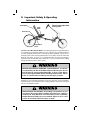
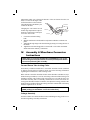
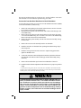
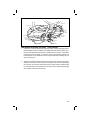
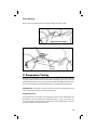
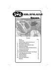
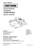
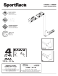
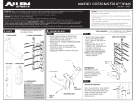
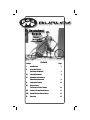
Recumbent
Bicycle
Owner’s
Instruction
& Safety Manual
Section
Contents
Page
I.
Introduction
2
II.
Important Safety &
Operating Information
3
III.
Sizing Adjustments
5
IV.
Assembly Instructions &
Wheelbase Conversion
9
V.
Suspension Tuning
15
VI.
Accessories &
Trailercycle/Trailer Towing
16
VII.
Fastener Torque Specifications
17
VIII.
Helpful Hints for Novice Riders
18
IX.
Warranty
19
I. Introduction
Congratulations! You have made a smart choice in selecting a Burley recumbent.
Your new recumbent has been engineered to provide years of top quality performance, comfort and enjoyment. To show our confidence, we offer a lifetime warranty on the frame and fork and a 180-day warranty for other original equipment
parts. [See warranty for details.)
Complete the following for your own records:
Date of Purchase: _______________________
Purchased From: _______________________________________________
(Retailer name and location)
Model: ________________________ Serial #: ________________________
(located on right-rear dropout)
Verify that you have received the following information with your
new Burley recumbent:
• Burley Adult Owner s Manual for Multi-Speed Bicycles
• Recumbent Owner s Manual Supplement (This manual)
• Warranty Card
IMPORTANT: Read the Burley Adult Owner s Manual and Owner sManual
Supplement thoroughly for important safety, maintenance and operating information. Keep the Burley Owner s Manual and Owner s Manual Supplement for future
reference. If you loan or sell your bicycle, be sure to provide these instructions and
allow enough time for new riders to read them carefully.
CHECK YOUR BRAKE CABLE ENGAGEMENT: Before you begin every
ride, or move the steering mast fore/aft, depress the front and rear
brake levers to ensure proper brake cable engagement. Failure to
do so could result in brake cables that are not properly engaged
which could in turn result in an accident and serious injury or death.
If you have questions or concerns about the length of your brake
cables, contact your local dealer for assistance.
2
II. Important Safety & Operating
Information
Seat frame
Seat
base
Tilt and height-adjustable
steering mast
Rear shock
Suspension
pivot
Caution to New Recumbent Riders: The riding position and weight distribution
on recumbents is quite different than on average “upright” bicycles and contributes
to unique handling characteristics. Starting up from a standstill, turning at low
and high speeds, and cornering and braking in wet weather will all be somewhat
different from other bicycles. It is recommended that you become thoroughly
acquainted with the handling and performance of your recumbent before riding
among automobile traffic or other cyclists.
BECOME FAMILIAR WITH HANDLING CHARACTERISTICS: Your Burley
recumbent bicycle will handle differently from other bicycles. Do not
ride this bicycle among automobile traffic or other cyclists before
you are thoroughly familiar with its handling characteristics. Failure
to do so could result in accident and serious injury or death.
The addition of accessories, such as racks, trailers and trailercycles can affect the
handling of your recumbent. Add these accessories only after you are thoroughly
acquainted with your recumbent. Practice riding with these accessories in an open
area free of automobile traffic.
PRACTICE USING ACCESSORIES: The handling characteristics of your
recumbent will change with the addition of loaded racks, a trailer or
a trailercycle. Only add these accessories after you are completely
familiar with the handling of your recumbent. Failure to do so could
result in an accident and serious injury or death.
3
Rider Maximum Weight Restriction
All Burley recumbents are engineered for a maximum rider weight of 275 lbs.
(125 kg).
DESIGNED FOR MAXIMUM RIDER WEIGHT OF 275 LBS.: All Burley
recumbents are engineered for a maximum rider weight of 275 lbs.
(125 kg). Individuals heavier than 275 lbs. (125 kg) should not ride
these models. Failure to heed this warning may result in a frame failure
which could cause an accident resulting in serious injury.
Wheel/Heel Overlap
Most recumbent bicycles exhibit some amount of front wheel-to-foot overlap
when turning. This condition is described as the potential for the rider s foot to
come in contact with some part of the front wheel while pedaling and cornering
simultaneously. This condition is often noticed during low speed cornering, when
the front wheel steering angle is greatest.
It is important to become familiar with the extent of wheel-to- foot overlap, if any,
with your recumbent bicycle. To familiarize yourself with this condition, test ride
your bicycle in a safe, open space such as an empty parking lot.
IMPORTANT: It is important to learn where front wheel-to-foot overlap can occur so that you will know how to avoid it. To avoid overlap, learn the technique
of coasting through sharp turns.
AVOID WHEEL-TO-HEEL OVERLAP: Most recumbent bicycles exhibit
some amount of front wheel-to-foot overlap. A foot coming into contact with the front wheel may cause you to lose control of the bicycle,
and may cause an accident resulting in serious injury or death.
Handlebars and Forks
Some Burley recumbent models are equipped with a special lightweight handlebar.
This handlebar is designed specifically for recumbent bicycles and MUST NOT
BE USED ON ANY OTHER BICYCLE.
Handlebars of this type are identified by a warning label at the center of the bar.
This warning label will be covered by the handlebar stem when installed on the
bicycle. The warning label will be visible and obvious when the handlebar is removed from the handlebar stem.
4
DO NOT USE YOUR HANDLEBAR WITH ANY OTHER BICYCLE: Some
Burley recumbent models are equipped with a special lightweight
handlebar, identified by a warning label at the bar center. These
handlebars are designed specifically for recumbent bicycles and
MUST NOT BE USED ON ANY OTHER BICYCLE. Use of these handlebars
on other bicycles may result in a failure, which could cause an accident resulting in serious injury.
Some Burley recumbent models feature front forks with a protective plastic strip
at the top of the right side fork leg. This strip is designed to prevent scratching or
gouging damage to the fork from the drive chain. It is very important that these forks
are not allowed to become scratched or gouged and that damage to the surface of
the fork from the drive chain is prevented. It is very important that the protective
strip is replaced if it becomes warn or damaged. See your dealer or call Burley
Customer Service if you have questions about the fork in your bike.
REPLACE PROTECTIVE STRIP ON FORK WHEN DAMAGED: Some Burley
recumbent models feature front forks with a protective plastic strip
at the top of the right-side fork leg. Damage to the surface of these
forks could lead to the development of cracks, which could eventually cause the fork to fail. A fork failure will cause an accident that
could result in serious injury or death.
III. Sizing Adjustments
Important Sizing Information for Proper Riding Position
Recumbent bicycle sizing and fit criteria are different from upright bicycles. It is
very important to carry out the necessary adjustments to be sure your recumbent fits
you properly. A bike that does not fit properly is unsafe. It will be uncomfortable
and difficult to control.
FIT AND SIZE IMPORTANT: If your bicycle does not fit properly, you
may lose control and fall. If your new bike doesn’t fit, ask your dealer
to size it properly before you ride. Failure to do so may cause an
accident, resulting in serious injury or death.
Refer to the photo on page 6 for proper recumbent cycling riding position. Seat
fore-aft position and handlebar position affect your comfort, safety and ability to
control the bike.
5
Seat Track Adjustment
The seat assembly is fixed to the seat track
via quick-release mechanisms. It can be
easily moved by opening the quick-release
levers and sliding the seat on the track.
The seat quick-release mechanisms must
be fully closed before riding. If you have
any questions about the proper operation
of the quick-release mechanism, refer to
Section IV. Tech, B.3, of the Burley Adult
Owner s Manual for Multi-Speed Bicycles
or have your dealer provide instruction.
Under no circumstances should the bicycle be ridden without the seat quick-release
mechanisms properly adjusted and fully closed. If the quick-release mechanisms
are not closed with adequate force, the seat assembly may slide on the seat track.
When the quick-release mechanisms are closed properly, the seat assembly WILL
NOT SLIDE ON THE SEAT TRACK.
If the seat assembly is allowed to slide on the seat track, it will not slide off the
bike frame. Socket head bolts and special washers are installed at the rear of the
seat track to prevent the seat assembly from coming off. These important safety
features should not be removed from the bicycle.
CLOSE QUICK-RELEASE MECHANISM AND ADJUST PROPERLY: Riding
your bicycle with seat quick-release mechanisms open or improperly
adjusted can cause you to lose control, resulting in serious injury or
death.
Seat Fore-Aft Adjustment
Step 1. Seat Adjustment—While sitting on the bicycle, have an assistant hold you
upright or lean against a wall. Pedal backwards in the freewheeling direction to
position yourself on the seat and pedals. Stop pedaling with the crankarms parallel
to the ground. There should be a slight bend to the knee of the leg on the forward
pedal. If your leg is completely straight, the seat is positioned too far back on the
seat track. If the bend at the knee is too great, the seat is positioned too far forward
on the seat track.
Step 2. Seat Adjustment Check—Confirm the correct bend of your leg by again
sitting on the bike with the crankarms oriented parallel to the ground. Place the
heel of your foot on the center of the forward pedal. Your leg will be absolutely
straight when the seat is adjusted the correct distance from the pedals. This technique
should provide a slight bend at the knee when the ball of your foot is centered on
the pedal.
6
Steering Mast Adjustments
The steering mast assembly features separate handlebar height and tilt angle adjustments. These adjustments will allow you to set the handlebars at the appropriate
height and distance from your body. The correct adjustment will result in a 90°
bend at the elbow (see photo on page 6).
Steering Mast Height Adjustment
1.
2.
Loosen the binder clamp at the bottom of the steering mast upper tube.
Adjust the handlebars to the desired height and tighten the binder bolt.
IMPORTANT NOTE: There is a minimum required insertion of the steering mast lower tube into the steering mast upper tube. This minimum
insertion is required for proper strength of the steering mast assembly.
Under no circumstances should the steering mast height adjustment
be set so that the MINIMUM INSERTION mark on the lower tube is visible beneath the upper tube.
ADJUST STEERING MAST PROPERLY: The MINIMUM INSERTION mark on
the steering mast lower tube must not be visible below the steering
mast upper tube AT ANY TIME. If the steering mast height adjustment
is set beyond the MINIMUM INSERTION mark, the steering mast may
become damaged or break, which could cause you to lose control
and fall, causing serious injury or death.
CHECK YOUR BRAKE CABLE ENGAGEMENT: Before you begin every
ride, or move the steering mast fore/aft, depress the front and rear
brake levers to ensure proper brake cable engagement. Failure to
do so could result in brake cables that are not properly engaged
which could in turn result in an accident and serious injury or death.
If you have questions or concerns about the length of your brake
cables, contact your local dealer for assistance.
Steering Mast Tilt Range Adjustments
It is a good idea to check the tightness of your steering mast pivot bolt before and
after every ride. The steering masts on all 2004 recumbents (in this manual referred
to as Type 2 steering masts) have only the rearward tilt range setting adjustment.
Set the rearward tilt setting of the steering mast to the desired position by adjusting
the adjustment bolt as described above.
Some Type 2 offset stems feature a removable forward stop bolt. This bolt serves
7
to limit the extent to which the
steering mast can be folded
forward. If threaded inward
(clockwise) completely or
removed, the steering mast
can be folded completely flat
to rest on the bike frame. With
the seat assembly removed and
the steering mast folded flat,
the bike may be easier to load
into some vehicles.
Type 2 Steering Mast
Steering Mast
Lower Tube
Rear Tilt
Adjustment
Bolt
Forward Tilt
Stop Bolt
Adjustment
Lock Nut
Once the seat and steering
mast adjustments have been
Offset Stem
performed, the bike is ready
to ride. However, there are
other seat adjustments that may increase comfort and allow you to customize the
fit of your bike.
Fine Tuning Seat Adjustments for Comfort
Seat Back Recline Adjustment
The seat back recline is adjustable to several different position settings. Newer
riders may prefer a more upright setting. Experienced and performance-oriented
riders may prefer a fully reclined seat back.
To adjust the degree of seat back recline:
1. Note the position of the seat assembly on the seat track.
2. Open both seat quick-release mechanisms.
3. Note the position of the plastic seat slider blocks in the range of adjustment holes
provided. Note how moving the slider blocks to different adjustment holes changes
the recline angle of the seat frame.
4. Slide the seat fully rearward and remove seat assembly from the frame.
5. Hold the seat in your lap or place it on a suitable work surface or table.
6. Remove both seat quick-release mechanisms, being careful not to lose the selfcentering springs.
7. Install the quick-release mechanism with plastic slider blocks and self-centering
springs in the desired recline adjustment holes.
8. Install the seat assembly on the bike by sliding the seat onto the seat track from the
rear (opposite of removal). Slide the seat frame to its original position on the seat
track.
9. Close both seat quick-release mechanisms. (Refer to Section IV. Tech B.3, of the
Burley Adult Owner s Manual for Multi-Speed Bicycles for proper quick-release
mechanism operation.)
Seat Bottom Fine Tuning Adjustments
Seat Bottom Fore-Aft and Tilt Range Adjustments: The fore-aft and tilt range
8
adjustments enable you to change the distance of the seat bottom from the seat
back, as well as the tilt angle of the
seat bottom relative to the seat back.
These adjustments will enhance your
Seat Bottom
comfort on the bike.
Changing the seat bottom fore-aft
and tilt range adjustments requires a
6mm hex wrench and a 13mm open
end or box end wrench.
1.
2.
3.
4.
Seat Back
Seat Bottom
Fixing Bolt
Side Plate
Seat Tilt
Adjustment
Holes
Loosen the seat bottom fixing
bolts.
Slide the seat bottom to the desired fore-aft position within the seat frame side
plates.
Adjust the tilt angle range to the desired setting by raising or lowering the nose of
the saddle.
Tighten the seat bottom fixing bolts to 150-200 in/lb on a Corbin® seat bottom
and 80-100 in/lb on a Burley© Seat bottom.
IV.
Assembly & Wheelbase Conversion
Instructions
NOTE: Burley recumbents MUST BE FULLY ASSEMBLED by your dealer.
The following assembly information is intended primarily for the Dealer
Technician performing this assembly.
Forward Steerer Tube Locking Collar
Some Burley recumbent models have a convertible wheelbase feature (identified
by linkage steering with two headsets). Please review the following information
regarding the forward Steerer Tube Locking Collar.
Bikes with the convertible wheelbase feature utilize threadless (Aheadset™) style
headset bearing assemblies, as well as one locking collar not included with typical
threadless headsets. This locking collar is designed to act as both the spacer for
the headset assembly and as a secondary retention device for the steerer tube. As
with typical threadless headset assemblies, first adjust the bearing preload of the
headset bearings and then tighten the locking collar bolt. The M5 bolt of the clamp
should be tightened to 50–75 in/lb.
IMPORTANT: The locking collar is only used in the medium wheelbase
[MWB] setting [see wheelbase conversion instructions].
Linkage Assembly
For bikes with the convertible wheelbase feature and linkage steering, please review
the following linkage assembly information.
9
1.
The linkage rod attaches the rear steerer to the front fork. Notice that one end
of the linkage rod has the bearing and nuts tightened against each other with no
gap. The other end has a gap and the nuts are tight. Also notice that the hardware
necessary to attach the linkage rod to the brackets is installed on the linkage assembly. To install the linkage rod, you will need to remove the hardware.
2.
Attach the side of the linkage rod with NO gap to the bracket on the fork using
an M6 x 25mm bolt. IMPORTANT: The linkage rod must be installed to the
bottom face of the mounting brackets on the fork and rear steerer tube. Place two
flat washers between the bearing and the fork bracket. Tighten the bolt to 90-100
in/lb.
3.
Adjust the linkage rod length so that the fork is centered and facing forward and
the bracket of the rear steerer is perpendicular to the main frame of the bike.
4.
Using a 10mm wrench, tighten one nut on the linkage rod against the bearing
(11mm wrench). Tighten the other nut against the linkage rod.
5.
Attach the linkage rod to the bottom face of the rear steerer bracket with one flat
washer between the bracket and the bolt head and one flat washer between the
bearing and the nut. Tighten the assembly to 90-100 in/lb. Wheelbase Conversion
Wheelbase Conversion
Some Burley recumbent models can be configured as either a short wheelbase
[SWB] or medium wheelbase [MWB] recumbent. This feature provides two
distinctly different handling characteristics. In the SWB setting, the bike delivers
a quick-handling, sporty ride. In the MWB setting, the bike has a slightly slower
steering feel and is smoother over bumps.
Please review the following procedure to perform the wheelbase conversion on
bikes with this feature. Such bicycles are assembled in the Medium Wheelbase
(MWB) setting at the factory, hence these instructions cover the conversion from
MWB to Short Wheelbase (SWB).
10
Special tools and knowledge are required to carry out the wheelbase conversion.
The wheelbase conversion must be performed by your dealer.
Conversion from Medium Wheelbase to Short Wheelbase
Use the following procedure for conversion from the Medium Wheelbase (MWB)
to the Short Wheelbase (SWB) setting:
1.
2.
3.
4.
Remove the steering linkage rod. Note flat washer locations. Save the rod assembly for future reconversion to the MWB setting.
Disconnect the front brake cable at the brake. The 160mm cable housing is used
in the SWB setting.
Remove the top cap and steerer tube clamp from the fork. The steerer tube clamp
is not used in the SWB setting. Save it for future reconversion to the MWB setting.
Remove the front fork from the forward head tube.
Remove the steering mast assembly from the rear steerer tube assembly, leaving
all cables intact.
5.
Remove the rear steerer tube assembly from the rear head tube.
6.
Install the fork in the rear head tube after repacking the headset bearing components if required.
7.
Install the steering mast on the fork steerer tube. Adjust bearing preload and
tighten the handlebar stem.
8.
Connect the front brake cable and adjust the front brake. [Route the cable housing behind the rear head tube with the brake pipe oriented horizontally, facing
rearward.]
9.
Remove the forward headset cups from the forward head tube if desired.**
10. Recheck headset and brake adjustments and all fasteners for proper torque before
riding.
** To keep from losing pieces, the rear steerer tube can be installed in the forward head tube.
To do this, do not remove the headset cups. Install the rear steerer tube using the same headset
assembly pieces, steerer tube clamp and linkage assembly.
AUTHORIZED BURLEY DEALER REQUIRED TO MAKE CONVERSION: Some
Burley recumbent models have a convertible wheelbase feature.
The wheelbase conversion requires special tools and knowledge.
This conversion should only be carried out by an authorized Burley
dealer. Incorrect wheelbase conversion will result in improper adjustment of critical components such as headset bearings, steering
linkage or brakes, and could cause an accident resulting in serious
injury or death.
11
Corbin Seat Bottom
Nylon Slider Blocks
Pivot Block Pin
Seat Frame
Seat Bottom
Fixing Bolt
Seat Bottom
Bracket
Washer
Lock Washers
Seat Frame
Side Plates
QR Rod
Pivot Block
Self-Locking
Nut
Aluminum Slider
Blocks
Seat Bottom Assembly for Corbin® Seat Bottoms
1.
Unpack the seat frame and the seat bottom from their separate packaging. Notice
that the hardware for the seat bottom is installed on the seat bottom brackets. Also,
the QR s and aluminum slider blocks are installed on the seat frame. To install the
seat bottom in the seat frame you must first remove the hardware from the seat
bottom brackets. This installation is easiest if performed before installing the seat
frame on the bicycle.
2.
Slide the seat bottom brackets between the two sides of the seat frame side plates.
Install the pivot blocks from the inside by inserting the pivot block pin through
the hole in the seat bottom bracket and then through the slot of the seat frame side
plates. Install the large diameter washer onto the fixing bolt and insert the bolt (from
the outside) through the slot in the seat frame side plates and seat bottom brackets
and pivot blocks. Install the M8 nut onto the bolt with a 13mm wrench. Tighten
the system to 150-200 in/lb.
12
Burley Seat Bottom
Seat Frame
Seat Bottom
Fixing Bolt
Seat Bottom
Bracket
Washer
Pivot Block
Seat Frame
Side Plates
QR Rod
Self-Locking
Nut
Aluminum Slider
Blocks
Seat Bottom Assembly for Burley® Seat Bottoms
1.
Unpack the seat frame and the seat bottom from their separate packaging. Notice
that the hardware for the seat bottom is installed on the seat bottom brackets. Also,
the QR s and aluminum slider blocks are installed on the seat frame. To install the
seat bottom in the seat frame you must first remove the hardware from the seat
bottom brackets. This installation is easiest if performed before installing the seat
frame on the bicycle.
2.
Slide the seat bottom brackets between the two sides of the seat frame side plates.
Install the pivot blocks from the inside by inserting the a bolt with a washer through
the seat frame, the composite seat bottom bracket, another washer, and then an M8
nut. Continue this process until all four seat block holes have bolts running through
them. Tighten each bolt to 80-100 in/lb.
13
Cable Housing Lengths and Routing
The cable housing lengths at the lower portion of the steering mast are set to fit
the mast in an extended adjustment position. If the steering mast needs to be set
close to the shorter end of the adjustment range, the housing lengths may need to
be adjusted to avoid contact with other moving parts.
ADJUST CABLEHOUSING LENGTH APPROPRIATELY: Cable housing may interfere with moving parts, such as the drive chain or
lower handlebar stem, which may cause you to lose control
and fall. Be sure to adjust cable housing lengths appropriately
after making adjustments to steering mast extended length.
TYPE 2 steering masts have cable housing stops at the left, or non-drive side of
the fore-aft centerline. Both brake cable housings are routed to the rear pair of
cable housing stops. Both gear cable housings are routed to the forward cable
housing stops.
Cable Routing for Type 2
Steering Masts (Steering
mast upper tube shown)
CHECK YOUR BRAKE CABLE ENGAGEMENT: Before you begin every
ride, or move the steering mast fore/aft, depress the front and rear
brake levers to ensure proper brake cable engagement. Failure to
do so could result in brake cables that are not properly engaged
which could in turn result in an accident and serious injury or death.
If you have questions or concerns about the length of your brake
cables, contact your local dealer for assistance.
14
Chain Routing
Please refer to the photos below for proper routing of the drive chain.
Single Idler Recumbent
Chain
in front
Chain
in rear
Nasoke with two idlers
V. Suspension Tuning
Burley Nasoke and Spider recumbents are equipped with rear suspension featuring
a custom-tuned air shock. This shock absorber is adjustable to provide proper suspension performance for a wide variety of rider weights and riding preferences. Refer
to the enclosed literature from the manufacturer for adjustment specifications.
IMPORTANT: This shock is only rated to 300 psi. Do not exceed 300 psi in your
Cane Creek shock. Damage to the shock may result!
Suspension Pivot
The suspension pivot assembly is designed to provide years of maintenance-free
performance. The pivot should never exhibit any play or "slop". If you have any
questions about the condition of the suspension pivot, do not ride the bicycle. Have
your dealer inspect the suspension pivot.
15
VI. Accessories and Trailer Towing
Accessories
Several accessories are available from your Burley recumbent dealer which will
add to the enjoyment and utility of your recumbent.
Kickstand Adaptor: This kit enables easy installation of rear mount-type kickstands
to all Burley recumbent models.
Workstand Adaptor: Designed for the professional and home mechanic, the
Workstand Adaptor engages the recumbent seat track and provides for easy fixturing of the recumbent to a conventional bicycle workstand.
Rack Installation Kits: Rack Installation Kits adapt most popular touring racks,
including the Moose Rack™, to fit Burley recumbents. See your dealer for the
Rack Installation Kit for your model.
Alternative Hitch: To pull a Burley child or cargo trailer, use the quick-release
Alternative Hitch with all Burley recumbents.
Rear Rack Installation and Use
Rear touring racks may be used with Burley recumbents. A Burley recumbent rack
installation kit will be necessary to install a rear rack to your recumbent. Rear racks
install to the forwardmost threaded boss on the chainstay or the swingarm of the
recumbent frame and to the dropout eyelet near the rear wheel axle. See your dealer
for the installation kit for your Burley recumbent model.
Trailer Towing
Burley child and cargo trailers may be towed by a Burley recumbent. Use of the
Burley Alternative Hitch™ is required. See your Burley Dealer for information
about the Alternative Hitch.
IMPORTANT: It is very important that you read the Burley Trailer Owner s Manual
thoroughly for important safety, maintenance and operating information
16
VII. Fastener Torque Specifications
Suspension pivot retaining bolt
90-100 in/lb.
Strut fixing bolts
50-65 in/lb.
Swingarm strut and rack mount bolts
50-65 in/lb.
Steering linkage rod attachment bolts
100–120 in/lb.
Upper shock mount bolt
150–200 in/lb.
Lower shock mount bolt
150-200 in/lb.
Idler wheel mount bolt
150–200 in/lb.
Corbin seat bottom fixing bolts
150-200 in/lb.
Burley seat bottom fixing bolts
80-100 in/lb.
17
VIII. Helpful Hints for Novice Riders
1.
Your foot should be positioned with the pedal under your arch, not under the ball
of your foot as with most bikes.
2.
The amount of seat back recline is a matter of personal preference. A more laid
back position distributes body weight over a larger area and is most comfortable
for longer rides. An upright position is more comfortable for most beginners, and
makes looking over the shoulder much easier.
3.
The steering mast can be adjusted for height and lean-back. If it s set too high the
handlebar may obstruct your view; too low and your knees may hit your hands.
A 90° bend at the elbows with the bar ends pointing down and slightly forward is
a common setting.
4.
Starting off from a standstill requires a good push on your first pedal stroke to
gain some momentum for balance. Place the pedal at the top of the stroke (12
o clock) on your strong side. Choose a low gear.
5.
It takes very little input from the handlebars to steer the recumbent. Relax your
upper body, particularly your shoulders, arms and hands. Failure to do so is a
common problem for beginning riders.
6.
You will be pushing against the seat back as you pedal. Try to focus the effort to
your middle back for more power. Avoid pulling on the handlebars.
7.
Try to develop a smooth, circular pedal stroke.
IX. WARRANTY
Burley Bicycle Limited Warranty
Burley will repair or replace any original equipment parts it
determines to be defective for a period of 180 days from date
of purchase at no charge; the frame and fork have a lifetime
warranty. The owner of a Burley bicycle must present his/her
bicycle for repair, within the warranty period, at an authorized
Burley dealer, together with an original sales receipt or similar
proof of purchase. This warranty applies only to the original
owner and is nontransferable. This warranty does not apply if the
recommended weight limit for Burley recumbents is exceeded.
Burley cannot be responsible for failure due to improper assembly, modification of parts or instructions, neglect, abuse,
accident, and/or normal wear. The warranty does not cover
any bikes used for rental, competition, or commercial use.
Burley neither assumes nor authorizes any person to assume any
other liability in connection with Burley bicycles, and there are
no oral agreements or warranties collateral to or affecting this
agreement. Any implied warranty of merchantability or fitness
for a particular purpose is limited in duration to the duration
of this warranty. Some states do not allow a limitation on how
long an implied warranty lasts, so the limitation may not apply
to you. This warranty gives you specific legal rights and you
19
About Burley Design Cooperative
Burley has been supplying products to the bicycle industry since 1975. Burley
products are designed and manufactured at our Eugene, Oregon shop. As workerowners of our cooperatively owned business, we bring an uncommon degree of
personal pride and attention to our work. Use our products with confidence and
satisfaction!
Burley Design Cooperative • 4020 Stewart Rd. • Eugene, OR 97402 USA
(541) 687-1644 • Fax (541) 687-0436 • www.burley.com
[email protected]
Copyright ©2004 by Burley Design Cooperative
“Burley” is a registered trademark of Burley Design Cooperative
Printed on recycled paper
rev 10/04