1
Xcel / AccuSense CHARGE SERIES
FULLY AUTOMATIC MULTI-CHEMISTRY BATTERY
CHARGER
Features:
•
•
•
•
•
Fully Automatic - starts and stops charging automatically
5 L.E.D. display to easily interpret charge and/or charge error conditions
Charge algorithm controls BOTH voltage and current for precise charging
Microprocessor-based control implements an intelligent charge
Inhibit Lockout circuit (optional) prevents vehicle operation while charging
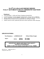
SPECIFICATIONS:
Part Numbers:
z-24E020-04-HF
Input:
z = 1:
z = 2:
120Vac,
230Vac,
24Vdc 20Adc Output
50 / 60Hz
50 / 60Hz
IMPORTANT: READ AND SAVE THIS SAFETY
INSTRUCTION MANUAL
KEEP IT WITH OR NEAR CHARGER AT ALL TIMES
Manual P/N:
MNUL0019 Rev.4
Copyright © 2013 DPI
1
Table of Contents
Section
1
2
3
4
5
Description
User Safety
Installation
Grounding
Preparing to Charge
5-Stage Charge
Pg
2
3
3
4
5
Section
6
7
8
9
10
Description
L.E.D. Display
Troubleshooting
Technical Notes
External Wiring
Warranty
Pg
6
7
9
10
11
Throughout this manual, look for this symbol. It means BE ALERT – YOUR
SAFETY IS INVOLVED. If you do not follow these safety instructions, personal
injury or property damage may occur.
1. User Safety Operations Guide
WARNING - RISK OF EXPLOSIVE GASES.
WORKING WITH RECHARGEABLE BATTERY(s) IS DANGEROUS.
EXPLOSIVE GASES DEVELOP DURING NORMAL BATTERY OPERATION.
READ THIS MANUAL EACH TIME AND MAKE CERTAIN YOU FULLY
UNDERSTAND IT AND FOLLOW THE SAFETY AND OPERATING
INSTRUCTIONS AT ALL TIMES.
• To reduce risk of battery explosion, follow all safety instructions below and
those published by the battery manufacturer. Review cautionary markings on
vehicle or equipment containing the battery.
• Use of an attachment not recommended or sold by the battery charger
manufacturer may result in a risk of fire, electric shock or injury to persons.
• Do not operate this charger if it has received a sharp blow, was dropped or
otherwise damaged in any manner. Refer to a qualified service agent.
• Charger contains no serviceable parts. If it fails during its warranty period,
contact your dealer for a warranty replacement.
• To reduce risk of electric shock, unplug charger from AC outlet before
attempting any maintenance or cleaning.
• For external cleaning use a clean damp towel.
• Have your distributor, dealer or other qualified service agent, repair or
replace worn or damaged parts immediately. Repairs should not be
attempted by people who are not qualified.
• Whenever removing AC Plug from the receptacle, pull from the Plug Body;
Not from the cord.
• Do not operate the charger if it is malfunctioning. Personal injury or property
damage could result.
•
•
•
Personal Precautions While Working With Batteries
Have someone within range of your voice to come to your aid if needed.
Have plenty of fresh water and soap nearby in case battery acid contacts
your skin, clothing or eyes. Wear eye and clothing protection and avoid
touching eyes.
2
•
•
•
•
•
•
If battery acid contacts skin or clothing, wash immediately with soap and
water.
If acid enters eye, immediately flush eye with running cold water for at least
10 minutes. Get medical attention immediately.
NEVER smoke or allow a spark or flame in vicinity of battery.
Be extra cautious not to drop a metal tool onto battery. It might spark or short
circuit battery or other electrical part that may cause an explosion.
Remove personal metal items such as rings, necklaces, watches, etc.
Batteries can produce a short-circuit current high enough to weld such items
causing a severe burn.
NEVER charge a frozen battery. Thaw it out for safer and more efficient
charging.
WARNING: CHARGERS CAN IGNITE FLAMMABLE MATERIALS AND
VAPORS. DO NOT USE NEAR FUELS, GRAIN DUST, SOLVENTS, OR OTHER
FLAMMABLES. TO REDUCE THE RISK OF AN ELECTRIC SHOCK, KEEP THE
CHARGER DRY. DO NOT EXPOSE IT TO RAIN OR WATER.
2. Installation
•
The use of an improper extension cord could result in a risk of a fire or
electric shock. If an extension cord must be used, it must be UL and/or CSA
approved. Locate all cords so that they will not be stepped on, tripped over or
otherwise subjected to damage or stress. Extension cord must be properly
wired and in good electrical condition, and large enough for the AC rating of
charger as specified in this TABLE:
RECOMMENDED MINIMUM AWG SIZE FOR
EXTENSION CORDS FOR BATTERY CHARGERS
Length of cord (feet):
25
50
100
150
AWG size of cord:
16
16
14
12
•
Accessories List:
AC Cord- 3 conductor: 18AWG power cable, with IEC 60320 power
connector and a NEMA 5-15 3 pole power plug.
3. Grounding Instructions
•
This battery charger must be grounded to reduce the risk of electric shock.
This charger is equipped with an AC cord set having an equipmentgrounding conductor. This AC cord set must be connected to an appropriate
receptacle that is properly installed and grounded in accordance with the
National Electrical Code and all local codes and ordinances.
WARNING: IMPROPER CONNECTION OF THE EQUIPMENT-GROUNDING
CONDUCTOR CAN RESULT IN A RISK OF AN ELECTRIC SHOCK.
3
•
The conductor with insulation having an outer surface that is green, with or
without yellow stripe(s), is the equipment-grounding conductor. If repair or
replacement of the charger’s AC cord set is necessary, refer to a qualified
service agent, and do not connect the equipment-grounding connector to a
live terminal.
4. Preparing to Charge
WARNING: The instructions printed on the charger are for daily
reference. For your own protection, when using ANY type of charger,
always ensure that the batteries in your Battery Pack ARE ALL at the
same state of charge, same condition, same size, and same rating. DO
NOT MIX DIFFERING BATTERY SIZES, BATTERY TYPES OR OLD
BATTERIES WITH NEW. Never use charger for any purpose contrary to
its intended purpose of charging lead acid batteries in accordance with
ALL instructions printed in this manual.
4.1 Be sure area around battery is well ventilated while battery is being charged.
Gas can be forcefully blown away using a non-metallic material like
cardboard.
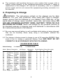
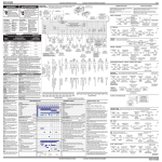
4.2 The charger is factory preset to charge in one of 32 operating MODES. Each
mode is set to charge a particular Battery Pack AND MUST BE SET
CORRECTLY IN ACCORDANCE WITH THE FOLLOWING:
‘CHARGE MODE TABLE’:
Switch Setting:
0 = Switch Up
1 = Switch Down
Mode Battery Description
AH Range
01
02
03
04
05
06
07
08
09
10
11
12
13
14
15
16-32
180-225AH
180-225AH
180-225AH
180-225AH
225-300AH
225-300AH
225-300AH
225-300AH
60-100AH
60-100AH
60-100AH
60-100AH
180-225AH
180-225AH
150-200AH
Exide
Flooded
US Battery Flooded
Trojan
Flooded
US Battery AGM
Exide
Flooded
US Battery Flooded
Trojan
Flooded
Full River AGM
Exide
Flooded
US Battery Flooded
Trojan
Flooded
Full River AGM
East Penn Gel
Full River AGM
BMZ
LiFePO4
Empty – Do Not Use
Absorption
Voltage
28.8V
30.8V
28.6V
28.8V
28.8V
30.8V
28.6V
29.4V
28.8V
30.8V
28.6V
29.4V
28.0V
29.4V
28.0V
4
Switch Setting (5-key left to right)
1
2
3
4
5
0
0
0
0
0
0
0
0
0
1
0
0
0
1
0
0
0
0
1
1
0
0
1
0
0
0
0
1
0
1
0
0
1
1
0
0
0
1
1
1
0
1
0
0
0
0
1
0
0
1
0
1
0
1
0
0
1
0
1
1
0
1
1
0
0
0
1
1
0
1
0
1
1
1
0
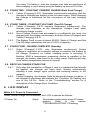
4.3 For 4 consecutive seconds, upon connection to AC Power, the Front Panel
L.E.D.s will flash a pattern to annunciate the mode setting as Described in
the following table where ‘0’ = Off, and ‘1’ indicates LED Flashing:
‘L.E.D. CHARGE MODE INDICATOR TABLE’:
LED’s – Left to Right
Mode Setting
1
2
3
4
5
0
0
0
0
0
0
0
0
0
0
0
0
0
0
0
0
0
0
0
0
0
0
1
1
1
1
1
1
1
1
0
0
0
1
1
1
1
0
0
0
0
1
1
1
1
0
1
1
0
0
1
1
0
0
1
1
0
0
1
1
1
0
1
0
1
0
1
0
1
0
1
0
1
0
1
MODE-1
MODE-2
MODE-3
MODE-4
MODE-5
MODE-6
MODE-7
MODE-8
MODE-9
MODE-10
MODE-11
MODE-12
MODE-13
MODE-14
MODE-15
Mode 16 to 32 are empty – selection of a mode in this range produces an error and the charger will
not operate – refer to the Error Table below.
5. FIVE(5)-STAGE CHARGE
5.1.
5.2.
5.3.
The following instructions assume the charger is operating in MODE-1.
Upon A.C. POWER connection, and for the first 4 seconds, the MODE is
annunciated where the Right Most L.E.D. only, flashes. This is the code
for MODE-1 and this MODE is applicable to that Battery Type listed in
the CHARGE MODE TABLE. Following the Start-Up Flash Sequence,
the ‘Power On’ L.E.D. will illuminate to indicate that AC power is applied;
the charger then commences charging as described below.
The charger may be left connected to battery with the A.C. Power
Removed. The amount of drain from the battery is minimal.
DPI’S 5-Stage Charging Process works as follows:
5.4. STAGE ONE - PRE-QUALIFICATION TEST
5.4.1. Yellow (Charging), Light Emitting Diode (L.E.D.), flashes on/off
SLOWLY at a rate of once per second during this stage. This stage
applies tests to the battery pack. Further charging is prohibited if the
charger discovers a fault such as connection of 24v charger to a 12V
battery pack or reversed battery connections, etc. Refer to Section 7
- ‘Troubleshooting Guide’ for understanding faults.
5.4.2. Duration of this stage is dependent on the condition of battery approximately 10 seconds under average circumstances, but if your
battery pack was allowed to severely discharge to less than 10.5v
5
(for every 12v battery), then the charger may take several hours of
slow charging to try to slowly bring the battery up beyond 10.5Vdc.
5.5. STAGE TWO - CONSTANT CURRENT CHARGE (Bulk Peak Charge)
5.5.1. Yellow (Charging) L.E.D. illuminates continuously indicating that the
charger is charging the battery at the full rated output. While charging,
the voltage is monitored for the occurrence of the next charging
stage.
5.6. STAGE THREE - CONSTANT VOLT/AMP (Top-Off Charge)
5.6.1. Yellow (Charging) L.E.D. remains illuminated continuously. The
charger now regulates at the Absorption Voltage Level while
monitoring charge current.
5.6.2. Once Charge Current has decreased to a sufficiently low level, the
charger then illuminates continuously, both the Green (Charged) and
Yellow (Charging) L.E.D.
5.6.3. The Battery Pack is now at about 80-90% State of Charge and this
Top-Off stage replenishes the last 10-20% of capacity.
5.7. STAGE FOUR - CHARGE COMPLETE (Standby)
5.7.1. Green (Charged) L.E.D., only, illuminates continuously. Output
Voltage is regulated at a reduced voltage to maintain the battery at
full charge. However, no further charging action is occurring. If
flashing, AND a temperature measuring device is installed in the
charger, the battery was found to be overly warm. Flashing will stop
once battery temperature returns to normal.
5.8. RECYCLE CHARGE STAGE FIVE
5.8.1. Only after the completion of Stage 4, and if a substantial load should
be applied, the charger will reset itself; thereby automatically
initiating a new charge cycle routine and restoring battery to full
capacity.
5.8.2. If while charging, the charger finds an abnormal charge condition, it
will attempt to shutdown and indicate the ‘Condition’ by flashing any
one of the L.E.D.s Refer to the ‘Troubleshooting’ section for a
description of the Charge Error Condition.
6. L.E.D. DISPLAY
While A.C. Power Is Connected….
Under normal charge circumstances, the L.E.D.s operate as follows:
{ Power On
(Red)
Illuminates continuously when AC power
present.
Refer
to
the
section
‘TROUBLESHOOTING’ if Flashing.
6
{ Shutdown
(Red)
Normally not illuminated. Refer
‘TROUBLESHOOTING’ if Flashing.
{ Detection
(Red)
Illuminates when battery not connected or
battery voltage is less than 8V. Refer to
‘TROUBLESHOOTING’ if Flashing.
{ Charging
(Yellow) Charge Status Indicator – flashes or
illuminates during the 5-Stage Charge
Process. Refer to Section 5.
{ Charged
(Green)
to
Illuminates continuously during the 4
Stage of the Charge Process.
th
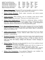
7. TROUBLESHOOTING GUIDE
To be able to troubleshoot safely and effectively, it is important to read this guide
completely before beginning any tests.
WARNING: DO NOT DISASSEMBLE THE CHARGER. TAKE IT TO A
QUALIFIED SERVICE AGENT WHEN SERVICE OR REPAIR IS REQUIRED.
INCORRECT REASSEMBLY MAY RESULT IN A RISK OF ELECTRIC SHOCK
OR FIRE. THE FOLLOWING PROCEDURES ARE INTENDED ONLY TO
DETERMINE IF A MALFUNCTION MAY EXIST IN THE CHARGER.
DANGER: TO REDUCE THE RISK OF ELECTRIC SHOCK, ALWAYS
DISCONNECT THE CHARGER’S AC CORD SET FROM AC POWER AND ITS
DC CORD SET FROM BATTERIES BEFORE ATTEMPTING ANY
MAINTENANCE OR CLEANING
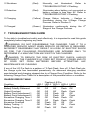
If any of the L.E.D.s flash in a pattern of ‘3-Fast-Flash, then off, 3-Fast-Flash etc,
the charge cycle has terminated prematurely. An abnormal charging condition
was detected and charging stopped due to a Charge Error Condition. Refer to the
following Charge Error Table for a description of the possible failure or condition.
CHARGE ERROR TABLE
Condition
Battery Voltage High
Battery Polarity Reversed
Output Overload
Battery Pack Unbalanced-1
Battery Pack Unbalanced-2
Excessive Charging Time-1
Excessive Charging Time-2
Excessive Overload
Battery Testing - 1
Battery Testing - 2
LED-1
Off
Off
Off
Off
Off
Off
Off
Off
Off
Off
Flashing L.E.D.s
LED-2 LED-3 LED-4
Off
Off
Off
Off
Off
Flash
Off
Off
Flash
Off
Flash Off
Off
Flash Off
Off
Flash Flash
Off
Flash Flash
Flash Off
Off
Flash Off
Off
Flash Off
Flash
7
LED-5
Flash
Off
Flash
Off
Flash
Off
Flash
Off
Flash
Off
Inhibit Control Defective
Battery Over Temperature
Internal Over Temperature-1
Internal Over Temperature-2
External Over Temperature
Mode-Selected Not Valid
Off
Off
Off
Off
Off
Flash
Flash
Flash
Flash
Flash
Flash
Off
Off
Flash
Flash
Flash
Flash
Off
Flash
Off
Off
Flash
Flash
Off
Flash
Off
Flash
Off
Flash
Off
•
Battery Voltage High. Charger’s DC cord set possibly connected to a battery
pack with voltage higher than the output rating of the charger.
•
Battery Polarity Reversed. Check output connector and ensure proper
polarity. Remake connections.
•
Output Overload. While charging, and, for example, under severe motor
loading, charger may shut down. This error is not very likely to occur.
•
Battery Pack Unbalanced-1,2. Caused by unbalanced battery condition.
Example: some batteries are at a much higher state of charge than others.
This may require replacement of the batteries. Refer to the Equipment’s
Operators manual for instructions on servicing the battery pack.
•
Excessive Charging Time-1,2. Occurs when charging took too long. Possible
causes include: use of a battery load that is draining energy from the battery
while the charger is trying to charge that same battery, aged or unbalanced
battery cell conditions, etc.
•
Inhibit Control Defective. Inhibit is supposed to be active, but it is not. Check
Inhibit vehicle wiring. If correct, internal inhibit switch may have been
overload – contact factory.
•
Excessive Overload. In the unlikely event that a heavy load is placed across
the battery pack while the charger is trying to charge the battery and the
charger cannot keep up with supplying energy to both the battery and the
load, and then the battery voltage will decrease. Further charging is
terminated.
•
Battery Testing. This error is only generated by one of two conditions found
during the Pre-Qualification Test Stage.
Condition 1: A severely discharged battery pack did not charge up to
10.5Vdc for 12v-system, or 21Vdc for 24V-system, within 3 hrs.
Condition 2: A heavy load, applied, prevents charger from charging
battery pack above 10.5Vdc for 12v-system, or 21Vdc for 24V-system.
•
Battery Over Temperature. If an external Thermistor was installed, the
charger ceased charging due to detecting a hot battery.
8
•
Internal Over Temperature-1,2. Charger shut down due to an internal over
temperature condition – check fan operation and remove blockages, if any.
8. TECHNICAL NOTES
•
Do not charge more than one battery pack at a time. Battery pack
characteristics differ and may cause the microprocessor to
function improperly.
•
If charging a series connected string of 2 or more batteries, ensure
that all batteries in the series connected string, are all at the same
state of charge, age type and condition.
•
The charger uses RF energy only for its internal functions.
Therefore its RF emissions are very low and are unlikely to cause
any interference in nearby electronic equipment.
•
The charger has an operating temperature range of -10C to +55C,
and a shipping/storage temperature range of -40C to +80C. It
needs to be stored in clean dry conditions.
•
Medical Electrical Equipment needs special precautions regarding
EMC and needs to be installed and put into service according to
the EMC information provided in this manual.
•
Portable and mobile RF communications equipment can affect
Medical Electrical Equipment.
•
The use of Accessories, transducers, and cables other than those
specified by the manufacturer, may result in increased Emissions
or decreased Immunity of the Battery Charger.
•
The Battery Charger should not be used adjacent to or stacked
with other equipment and that if adjacent or stacked use is
necessary, the Battery Charger should be observed to verify
normal operation in the configuration in which it will be used.
9
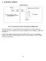
9. EXTERNAL WIRING
A.C. Convenience Port Accessory (Optional)
If the optional A.C. Convenience Port Accessory is include with your
system, the L.E.D. display mirrors the Charger L.E.D. Display – with one
exception:
If an L.E.D. pattern flashes from the center L.E.D. out, in a repeating
pattern, the Port is annunciating a ‘Lost Communications’ error. Check
wiring for continuity.
10
10. LIMITED WARRANTY
Diversified Power International LLC (DPI) warrants exclusively to the original purchaser that this
product will be replaced or repaired, at DPI’s option, if it fails during the first 10,000hrs (or 5yrs), of
operation, whichever comes first, after date of purchase due to a defect in material or workmanship.
In order for a claim to be processed the product must be returned to DPI (i) with all transportation
charges prepaid, (ii) accompanied by an acceptable proof of purchase, and with a Return Material
Authorization (RMA) number, previously obtained from DPI, printed and clearly visible on the outside
of the shipping container. This warranty does not apply if the product has been modified, abused, or
damaged or improperly or negligently used, connected, maintained, or operated in any manner
contrary to the instructions stated in this manual or affixed to the product’s enclosure. Repair or
replacement as provided under this warranty is the exclusive remedy of the purchaser, and the
purchaser shall have no claim against DPI except for the breach of an express warranty stated herein.
DPI shall not be liable for any incidental, consequential, or special damages for breach of any
expressed or implied warranty. Except to the extent required by applicable law any implied warranty
of merchantability or fitness for a particular purpose is limited in duration to the first 18mos after the
date of purchase. Some states do not allow the exclusion or limitation of incidental or consequential
damages or allow limitations on how long an implied warranty lasts, so the above limitations or
exclusion may not apply to you. This limited warranty gives you specific legal rights, and you may also
have other rights which vary from state to state. APART FROM THE WARRANTIES SET FORTH
ABOVE, DPI MAKES NO OTHER WARRANTY, EXPRESS OR IMPLIED, WITH RESPECT TO THE
SUITABILITY OR MERCHANTABILITY OF THIS PRODUCT, THE FITNESS OR THIS PRODUCT
FOR ANY SPECIFIC USE OR PURPOSE, OR ANY OTHER MATTER PERTAINING TO THIS
PRODUCT.
Return information:
DIVERSIFIED POWER INTERNATIONAL LLC
414 CENTURY COURT
PINEY FLATS, TN 37686, U.S.A.
423 538-9002
RMA # ________________
For further information, product updates, technical information, or general
inquiries, also, please visit our web site at:
www.DPIpower.com
11