1
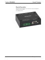
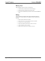
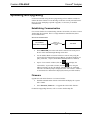
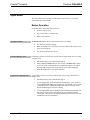
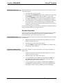
Crestron C2N-ANLZ
Cresnet® Analyzer
Operations Guide
This document was prepared and written by the Technical Documentation department at:
Crestron Electronics, Inc.
15 Volvo Drive
Rockleigh, NJ 07647
1-888-CRESTRON
All brand names, product names and trademarks are the property of their respective owners.
©2006 Crestron Electronics, Inc.
Crestron C2N-ANLZ
Cresnet® Analyzer
Contents
Cresnet® Analyzer: C2N-ANLZ
1
Introduction ............................................................................................................................... 1
Features and Functions ................................................................................................ 1
Applications................................................................................................................. 1
Specifications .............................................................................................................. 2
Physical Description.................................................................................................... 3
Industry Compliance ................................................................................................... 6
Setup .......................................................................................................................................... 7
Network Wiring........................................................................................................... 7
Hardware Hookup ....................................................................................................... 7
Memory Card .............................................................................................................. 8
Battery ......................................................................................................................... 8
Uploading and Upgrading.......................................................................................................... 9
Establishing Communication....................................................................................... 9
Firmware ..................................................................................................................... 9
Operation ................................................................................................................................. 10
Button Operation ....................................................................................................... 10
Console Operation ..................................................................................................... 11
Network Analyzer ..................................................................................................... 12
Problem Solving ...................................................................................................................... 13
Troubleshooting......................................................................................................... 13
Check Network Wiring.............................................................................................. 13
Further Inquiries ........................................................................................................ 14
Future Updates .......................................................................................................... 14
Return and Warranty Policies .................................................................................................. 15
Merchandise Returns / Repair Service ...................................................................... 15
CRESTRON Limited Warranty................................................................................. 15
Operations Guide – DOC. 6473
Contents • i
Cresnet® Analyzer
Crestron C2N-ANLZ
®
Cresnet Analyzer: C2N-ANLZ
Introduction
Features and Functions
•
•
•
•
•
Cresnet® Analyzer records Cresnet data at customer installations for
analysis by Crestron engineers
Logs Cresnet traffic and assesses the Cresnet network
Dual power – Cresnet Power (24 VDC) or included 9 Volt battery
backup
Logs analyzed data to included 512MB (expandable to 1GB)
multimedia memory card (MMC); USB 2.0 MMC-compatible card
reader included
Push-button operation for simple logging of data
Applications
The C2N-ANLZ is used to diagnose and record Cresnet problems at customer
installations. The C2N-ANLZ is capable of performing the following functions:
Operations Guide – DOC. 6473
•
Record Cresnet traffic data to included memory card
•
Log under-voltage events (i.e. power failure, wiring faults, etc.)
•
Provide Network Analyzer functionality for 2-Series control systems that do
not natively support it (i.e. QM-RMCRX and QM-RMCRX-BA)
Cresnet® Analyzer: C2N-ANLZ • 1
Cresnet® Analyzer
Crestron C2N-ANLZ
Specifications
Specifications for the C2N-ANLZ are listed in the following table.
C2N-ANLZ Specifications
SPECIFICATION
DETAILS
Power Requirements
Cresnet Power Usage
<1 Watt @ 24 Volts DC
Battery Backup (included)
9 Volt disposable Alkaline, 625 mAh;
Approximately 10 hours of full operation in
lieu of Cresnet power, 6 months on standby
Memory Card (included)
Size
512MB Multimedia Memory Card;
Upgradeable to 1GB
Format
FAT16, Microsoft® Windows® compatible
Data Logging
Via software or hardware command; logs
power interruptions and system startup
when powered by battery backup
Environmental
Temperature
41° to 104°F (5° to 40°C)
Humidity
10% to 90% RH (non-condensing)
Enclosure
Black metal, surface mount box
Dimensions
Height
1.25 in (3.18 cm)
Width
3.80 in (9.65 cm)
Depth
3.13 in (7.94 cm)
Weight
2 • Cresnet® Analyzer: C2N-ANLZ
9.6 oz (272 grams)
Operations Guide – DOC. 6473
Cresnet® Analyzer
Crestron C2N-ANLZ
Physical Description
This section provides information on the connections, controls, and indicators
available on your C2N-ANLZ.
C2N-ANLZ Physical View
Operations Guide – DOC. 6473
Cresnet® Analyzer: C2N-ANLZ • 3
Cresnet® Analyzer
Crestron C2N-ANLZ
C2N-ANLZ Overall Dimensions
6
1
2
3
4
5
3.13 in
(7.94 cm)
1.25 in
(3.18 cm)
3.80 in
(9.65 cm)
7
8
Connectors, Controls, & Indicators
#
CONNECTORS,
CONTROLS, &
INDICATORS
DESCRIPTION
1
PWR Light Emitting
Diode (LED)
Indicates the state of operation of the
C2N-ANLZ. Refer to “Operational Status” on
page 10 for more information.
2
NET LED
3
MARKER 1 & 2
BUTTONS
Indicates Cresnet activity on the Cresnet
bus.
Marker buttons are used to leave a marker in
the recorded log file that can note a specific
occurrence on a Cresnet network (i.e. an
unexpected event). Refer to “Mark Events in
the Log” on page 11 for more information.
(continued on following page)
4 • Cresnet® Analyzer: C2N-ANLZ
Operations Guide – DOC. 6473
Cresnet® Analyzer
Crestron C2N-ANLZ
Connectors, Controls, & Indicators (continued)
#
CONNECTORS,
CONTROLS, &
INDICATORS
DESCRIPTION
4
LOG BUTTON
The LOG button starts and stops data
logging to the memory card. Refer to “Log
Data to a Memory Card” on page 10 for more
information.
5
INIT BUTTON
The INIT button initializes and formats the
memory card. Refer to “Format a Memory
Card” on page 10 for more information.
6
MEMORY
Memory card slot for included removable
multimedia memory card. The memory card
can be inserted or removed when the
C2N-ANLZ is not logging data (LOG LED is
off).
7
NET PORTS
(2) Four-pin terminal block NET ports
connect the C2N-ANLZ between the control
system and the Cresnet network.
8
COMPUTER
One DB9, female, bidirectional computer
console port for connection to a PC. Use with
included straight serial cable.
5
9
Operations Guide – DOC. 6473
1
6
Pin 1: N/A
Pin 2: Receive Data (RD)
Pin 3: Transmit Data (TD)
Pin 4: Data Terminal Ready (DTR)
Pin 5: Signal Ground (G)
Pin 6: N/A
Pin 7: N/A
Pin 8: Clear To Send (CTS)
Pin 9: N/A
Cresnet® Analyzer: C2N-ANLZ • 5
Cresnet® Analyzer
Crestron C2N-ANLZ
Industry Compliance
As of the date of manufacture, the C2N-ANLZ has been tested and found to comply
with specifications for CE marking and standards per EMC and
Radiocommunications Compliance Labelling.
NOTE: This device complies with part 15 of the FCC rules. Operation is subject to
the following two conditions: (1) this device may not cause harmful interference, and
(2) this device must accept any interference received, including interference that may
cause undesired operation.
This equipment has been tested and found to comply with the limits for a Class B
digital device, pursuant to part 15 of the FCC Rules. These limits are designed to
provide reasonable protection against harmful interference in a residential
installation. This equipment generates, uses and can radiate radio frequency energy
and, if not installed and used in accordance with the instructions, may cause harmful
interference to radio communications. However, there is no guarantee that
interference will not occur in a particular installation. If this equipment does cause
harmful interference to radio or television reception, which can be determined by
turning the equipment off and on, the user is encouraged to try to correct the
interference by one or more of the following measures:
Reorient or relocate the receiving antenna.
Increase the separation between the equipment and receiver.
Connect the equipment into an outlet on a circuit different from that to
which the receiver is connected.
Consult the dealer or an experienced radio/TV technician for help.
6 • Cresnet® Analyzer: C2N-ANLZ
Operations Guide – DOC. 6473
Cresnet® Analyzer
Crestron C2N-ANLZ
Setup
Network Wiring
When wiring the network, consider the following:
•
Use Crestron Certified Wire.
•
Use Crestron power supplies for Crestron equipment.
•
Provide sufficient power to the system.
CAUTION: Insufficient power can lead to unpredictable results or damage
to the equipment. Please use the Crestron Power Calculator to help calculate
how much power is needed for the system
(http://www.crestron.com/calculators).
•
For larger networks, Use a Cresnet Hub/Repeater (CNXHUB) to maintain
signal quality
For more details, refer to “Check Network Wiring” on page 13.
Hardware Hookup
Connect the Device
Make the necessary connections as called out in the illustration that follows this
paragraph. Refer to “Network Wiring” on page 7 before attaching the 4-position
terminal block connector. Apply power after all connections have been made.
When making connections to the C2N-ANLZ, consider the following:
•
Use Crestron power supplies for Crestron equipment.
•
The included cables cannot be extended.
Hardware Connections for the C2N-ANLZ
NET 1:
TO CONTROL SYSTEM OR
CRESTRON POWER SUPPLY
Alternate Hookup
Operations Guide – DOC. 6473
NET 2:
TO CRESNET
NETWORK
COMPUTER:
TO PC
MEMORY:
INSERT INCLUDED
MEMORY CARD
If the analyzer cannot be easily accessed, connect the COMPUTER port to a serial
port on the control system. Use a remote connection to the control system’s serial
port to issue commands to the C2N-ANLZ.
Cresnet® Analyzer: C2N-ANLZ • 7
Cresnet® Analyzer
Crestron C2N-ANLZ
Memory Card
When installing the memory card, observe the following:
•
Insert the memory card with electrical contacts facing up.
•
Push in the memory card until it clicks into the socket.
•
The memory card should only be inserted or removed when the LOG LED
is off.
Battery
The C2N-ANLZ has a 9 Volt battery that is used as a backup in the absence of
Cresnet power. To install a battery, use a #2 Philips screwdriver and perform the
following:
8 • Cresnet® Analyzer: C2N-ANLZ
•
Remove memory card from C2N-ANLZ.
•
Remove the four cover screws from the top of the C2N-ANLZ.
•
Lift the top cover to expose the battery.
•
Remove the old battery from the battery socket, if one exists.
•
Install a fresh battery. Observe polarity.
•
Replace and secure the top cover with the cover screws.
Operations Guide – DOC. 6473
Cresnet® Analyzer
Crestron C2N-ANLZ
Uploading and Upgrading
Crestron recommends using the latest programming software and that each device
contains the latest firmware to take advantage of the most recently released features.
However, before attempting to upload or upgrade, it is necessary to establish
communication.
Establishing Communication
Use Crestron Toolbox for communicating with the C2N-ANLZ; refer to the Crestron
Toolbox help file for details. There is a single method of communication; direct
serial communication.
Direct Serial Communication
PC RUNNING
CRESTRON TOOLBOX
SERIAL VIA
STRAIGHT-THROUGH
CABLE
C2N-ANLZ
•
The COMPUTER port on the C2N-ANLZ connects to the serial port on
the PC via the included straight-through serial cable.
•
Use the Address Book in Crestron Toolbox to create an entry using the
expected serial communication protocol (RS232, auto-detect baud rate, no
parity, 8 data bits, 1 stop bit, XON/XOFF disabled, RTS/CTS enabled).
•
Open a “Text Console” window (click the
icon) or display the
icon); using the
C2N-ANLZ’s “System Info” window (click the
address book entry for the C2N-ANLZ; communications are confirmed
when the C2N-ANLZ prompt is displayed (in the “Text Console” window)
or when the device information is displayed (in the System Info window).
Firmware
Upgrade the C2N-ANLZ firmware via Crestron Toolbox.
•
Establish communications with the C2N-ANLZ and display the “System
Info” window.
•
Select Functions | Firmware… to upgrade the C2N-ANLZ firmware.
For details on upgrading firmware, refer to Crestron Toolbox help file.
Operations Guide – DOC. 6473
Cresnet® Analyzer: C2N-ANLZ • 9
Cresnet® Analyzer
Crestron C2N-ANLZ
Operation
The C2N-ANLZ can be operated from the buttons on the device or via console
commands from a connected PC.
Button Operation
Using the buttons on the C2N-ANLZ, you can:
Operational Status
Format a Memory Card
Log Data to a Memory Card
•
Format a memory card
•
Log Cresnet data to a memory card
•
Mark events in the log
The PWR LED indicates the operational status of the C2N-ANLZ:
•
Off: The C2N-ANLZ is sleeping
•
Blink: Operating from 9 Volt battery. The C2N-ANLZ will switch to a lowpower operating mode.
•
On: Operating from Cresnet power.
Formatting a memory card will erase any files that are stored on the card. To format
a memory card:
•
Install the memory card as described on page 8.
•
Press and hold the INIT button for five seconds. The INIT LED will turn
on. If text console communications are established with the C2N-ANLZ,
messages indicating the status of the format process will be displayed.
•
When the LED turns off, the card is formatted.
Logged data is written to a text file on the memory card. To log Cresnet data to a
memory card:
10 • Cresnet® Analyzer: C2N-ANLZ
•
Install the memory card as described on page 8.
•
To start logging data, press and release the LOG button. A new log file is
created and the LOG LED will light and then start blinking. If text console
communications are established with the C2N-ANLZ, a message will be
displayed indicating the start time of the log.
•
To stop logging data, press the LOG button. The LOG LED will light and
then turn off. If text console communications are established with the
C2N-ANLZ, a message will be displayed indicating the end time of the log
in addition to file size information.
Operations Guide – DOC. 6473
Cresnet® Analyzer
Crestron C2N-ANLZ
Mark Events in the Log
When troubleshooting, events can be marked in the log for future analysis. To mark
events while logging:
•
Start logging data as described above.
•
Press either of the MARKER buttons to place a marker in the log. Pressing
the MARKER 1 button will place the text “MARK 1” in the log file.
Pressing the MARKER 2 button will place the text “MARK 2” in the log
file. When a marker button is pressed, its corresponding LED will light.
•
To stop logging data, press the LOG button. The LOG LED will light and
then turn off. If text console communications are established with the
C2N-ANLZ, a message will be displayed indicating the end time of the log
in addition to file size information.
Once data has been logged, remove the memory card and use the included USB card
reader to email the log file(s) to Crestron for analysis.
Console Operation
Use the C2N-ANLZ console commands to perform many of the functions available
from the buttons on the C2N-ANLZ as well as retrieve information about the
C2N-ANLZ and the log files stored on the memory card.
Format a Memory Card
Log Data to a Memory Card
Operations Guide – DOC. 6473
Formatting a memory card will erase any files that are stored on the card. To format
a memory card:
•
Establish communications with the C2N-ANLZ and open a text console
window as described on page 9.
•
Install the memory card as described on page 8.
•
Type the FORMAT command and press the Enter key. The status of the
format process will be displayed.
Logged data is written to a text file on the memory card. To log Cresnet data to a
memory card:
•
Establish communications with the C2N-ANLZ and open a text console
window as described on page 9.
•
Install the memory card as described on page 8.
•
To start logging data, type the LOG command and press the Enter key.
The LOG LED will light and then start blinking. A message will be
displayed indicating the start time of the log.
•
To stop logging data, type the -LOG command and press the Enter key.
The LOG LED will light and then turn off. A message will be displayed
indicating the end time of the log in addition to file size information.
Cresnet® Analyzer: C2N-ANLZ • 11
Cresnet® Analyzer
Mark Events in the Log
Crestron C2N-ANLZ
When troubleshooting, events can be marked in the log for future analysis. When the
engineer reviews the log, he/she can search the log for the marker to locate the
instance that requires the engineer’s analysis. To mark events while logging:
•
While the C2N-ANLZ is logging data, enter the console command MARK
1 to place the text “MARK 1” in the log file.
•
While the C2N-ANLZ is logging data, enter the console command MARK
2 to place the text “MARK 2” in the log file.
Once data has been logged, remove the memory card and use the included USB card
reader to email the log file(s) to Crestron for analysis.
Other Commands
Other console commands can be used to obtain information on or control the
C2N-ANLZ. To use the following console commands, communications must be
established and a text console window must be opened as described on page 9:
•
DIR: Lists the file directory of the installed memory card. Wildcard
characters can be used. i.e. the command dir *.txt will list all files with a
“.txt” extension.
•
GET [filename]: Transfers a file from the memory card via XMODEM.
Advanced analysis tools are built into the C2N-ANLZ. These tools should only used
under supervision of a Crestron engineer when required. For more information,
contact Crestron.
Network Analyzer
The C2N-ANLZ can provide Network Analyzer functionality to 2-Series control
systems that do not have built-in Network Analyzer capabilities such as the
QM-RMCRX-BA. To use the C2N-ANLZ as a Network Analyzer:
•
Connect the C2N-ANLZ to Cresnet Network
•
Establish communications with the C2N-ANLZ as described on page 9.
•
Select the Network Analyzer tool by clicking the
icon. Refer to the
Crestron Toolbox help file for instructions on using Network Analyzer.
NOTE: The control system must be connected to the Cresnet network and must be
running a program that contains the connected network devices.
For more information on Network Analyzer, refer to the Crestron Toolbox help file.
12 • Cresnet® Analyzer: C2N-ANLZ
Operations Guide – DOC. 6473
Cresnet® Analyzer
Crestron C2N-ANLZ
Problem Solving
Troubleshooting
The following table provides corrective action for possible trouble situations. If
further assistance is required, please contact a Crestron customer service
representative.
C2N-ANLZ Troubleshooting
TROUBLE
POSSIBLE CAUSE(S)
CORRECTIVE ACTION
Device does not
function.
Device is not receiving
power.
Check that NET 1 connector is
connected to a Crestron control
system or a Crestron 24 VDC
power supply.
PWR LED does not
illuminate.
Power is not connected to
NET 1 connector or
battery is weak.
Connect power to NET 1
connector. Replace battery.
LOG LED does not
illuminate when
pressed.
Memory card not
installed.
Install memory card.
Memory card is full.
Remove data files from
memory card.
NET LED does not
illuminate when
C2N-ANLZ is
connected to a
control system.
C2N-ANLZ is not
synchronized to Cresnet
traffic.
On control systems with an
LCD front panel (i.e. PRO2 and
RACK2), perform a Cresnet
poll (press INFO button, then
NET button).
Poll the Cresnet network from
a Crestron Toolbox text
console window.
Restart the control system by
pressing HW-R or SW-R or by
cycling power.
Memory card does
not format.
Memory card is not
installed.
Install memory card.
INIT button is not held
long enough.
Hold INIT button for five
seconds.
Check Network Wiring
Use the Right Wire
In order to ensure optimum performance over the full range of your installation
topology, Crestron Certified Wire, and only Crestron Certified Wire, may be used.
Failure to do so may incur additional charges if support is required to identify
performance deficiencies because of using improper wire.
Calculate Power
CAUTION: Use only Crestron power supplies for Crestron equipment. Failure to do
so could cause equipment damage or void the Crestron warranty.
CAUTION: Provide sufficient power to the system. Insufficient power can lead to
unpredictable results or damage to the equipment. Please use the Crestron Power
Calculator to help calculate how much power is needed for the system
(http://www.crestron.com/calculators).
Operations Guide – DOC. 6473
Cresnet® Analyzer: C2N-ANLZ • 13
Cresnet® Analyzer
Crestron C2N-ANLZ
When calculating the length of wire for a particular Cresnet run, the wire gauge and
the Cresnet power usage of each network unit to be connected must be taken into
consideration. Use Crestron Certified Wire only. If Cresnet units are to be daisychained on the run, the Cresnet power usage of each network unit to be daisy-chained
must be added together to determine the Cresnet power usage of the entire chain. If the
unit is a home-run from a Crestron system power supply network port, the Cresnet
power usage of that unit is the Cresnet power usage of the entire run. The wire gauge
and the Cresnet power usage of the run should be used in the following equation to
calculate the cable length value on the equation’s left side.
Cable Length Equation
40,000
L<
RxP
Where: L = Length of run (or chain) in feet
R = 6 Ohms (Crestron Certified Wire: 18 AWG (0.75 MM 2 ))
or 1.6 Ohms (Cresnet HP: 12 AWG (4 MM 2 ))
P = Cresnet power usage of entire run (or chain)
Make sure the cable length value is less than the value calculated on the right side of
the equation. For example, a Cresnet run using 18 AWG Crestron Certified Wire and
drawing 20 watts should not have a length of run more than 333 feet. If Cresnet HP is
used for the same run, its length could extend to 1250 feet.
NOTE: All Crestron certified Cresnet wiring must consist of two twisted pairs. One
twisted pair is the +24V conductor and the GND conductor, and the other twisted pair
is the Y conductor and the Z conductor.
Strip and Tin Wire
When daisy-chaining Cresnet units, strip the ends of the wires carefully to avoid
nicking the conductors. Twist together the ends of the wires that share a pin on the
network connector, and tin the twisted connection. Apply solder only to the ends of the
twisted wires. Avoid tinning too far up the wires or the end becomes brittle. Insert the
tinned connection into the Cresnet connector and tighten the retaining screw. Repeat
the procedure for the other three conductors.
Add Hubs
For larger networks (i.e., greater than 28 network devices), it may become necessary to
add a Cresnet Hub/Repeater (CNXHUB) to maintain signal quality throughout the
network. Also, for networks with lengthy cable runs, it may be necessary to add a
Hub/Repeater after only 20 devices.
Further Inquiries
If you cannot locate specific information or have questions after reviewing this
guide, please take advantage of Crestron's award winning customer service team by
calling the Crestron corporate headquarters at 1-888-CRESTRON [1-888-273-7876].
For assistance in your local time zone, refer to the Crestron website
(http://www.crestron.com/) for a listing of Crestron worldwide offices.
You can also log onto the online help section of the Crestron website to ask
questions about Crestron products. First-time users will need to establish a user
account to fully benefit from all available features.
Future Updates
As Crestron improves functions, adds new features, and extends the capabilities of
the C2N-ANLZ, additional information may be made available as manual updates.
These updates are solely electronic and serve as intermediary supplements prior to
the release of a complete technical documentation revision.
Check the Crestron website periodically for manual update availability and its
relevance. Updates are identified as an “Addendum” in the Download column.
14 • Cresnet® Analyzer: C2N-ANLZ
Operations Guide – DOC. 6473
Crestron C2N-ANLZ
Cresnet® Analyzer
Return and Warranty Policies
Merchandise Returns / Repair Service
1.
No merchandise may be returned for credit, exchange, or service without prior authorization
from CRESTRON. To obtain warranty service for CRESTRON products, contact an
authorized CRESTRON dealer. Only authorized CRESTRON dealers may contact the factory
and request an RMA (Return Merchandise Authorization) number. Enclose a note specifying
the nature of the problem, name and phone number of contact person, RMA number, and
return address.
2.
Products may be returned for credit, exchange, or service with a CRESTRON Return
Merchandise Authorization (RMA) number. Authorized returns must be shipped freight
prepaid to CRESTRON, 6 Volvo Drive, Rockleigh, N.J. or its authorized subsidiaries, with
RMA number clearly marked on the outside of all cartons. Shipments arriving freight collect
or without an RMA number shall be subject to refusal. CRESTRON reserves the right in its
sole and absolute discretion to charge a 15% restocking fee, plus shipping costs, on any
products returned with an RMA.
3.
Return freight charges following repair of items under warranty shall be paid by CRESTRON,
shipping by standard ground carrier. In the event repairs are found to be non-warranty, return
freight costs shall be paid by the purchaser.
CRESTRON Limited Warranty
CRESTRON ELECTRONICS, Inc. warrants its products to be free from manufacturing defects in materials
and workmanship under normal use for a period of three (3) years from the date of purchase from
CRESTRON, with the following exceptions: disk drives and any other moving or rotating mechanical
parts, pan/tilt heads and power supplies are covered for a period of one (1) year; touchscreen display and
overlay components are covered for 90 days; batteries and incandescent lamps are not covered.
This warranty extends to products purchased directly from CRESTRON or an authorized CRESTRON
dealer. Purchasers should inquire of the dealer regarding the nature and extent of the dealer's warranty, if
any.
CRESTRON shall not be liable to honor the terms of this warranty if the product has been used in any
application other than that for which it was intended, or if it has been subjected to misuse, accidental
damage, modification, or improper installation procedures. Furthermore, this warranty does not cover any
product that has had the serial number altered, defaced, or removed.
This warranty shall be the sole and exclusive remedy to the original purchaser. In no event shall
CRESTRON be liable for incidental or consequential damages of any kind (property or economic damages
inclusive) arising from the sale or use of this equipment. CRESTRON is not liable for any claim made by a
third party or made by the purchaser for a third party.
CRESTRON shall, at its option, repair or replace any product found defective, without charge for parts or
labor. Repaired or replaced equipment and parts supplied under this warranty shall be covered only by the
unexpired portion of the warranty.
Except as expressly set forth in this warranty, CRESTRON makes no other warranties, expressed or
implied, nor authorizes any other party to offer any warranty, including any implied warranties of
merchantability or fitness for a particular purpose. Any implied warranties that may be imposed by law are
limited to the terms of this limited warranty. This warranty statement supersedes all previous warranties.
Trademark Information
All brand names, product names, and trademarks are the sole property of their respective owners. Windows is a registered trademark
of Microsoft Corporation. Windows95/98/Me/XP and WindowsNT/2000 are trademarks of Microsoft Corporation.
Operations Guide – DOC. 6473
Cresnet® Analyzer: C2N-ANLZ • 15
Crestron Electronics, Inc.
15 Volvo Drive Rockleigh, NJ 07647
Tel: 888.CRESTRON
Fax: 201.767.7576
www.crestron.com
Operations Guide – DOC. 6473
(2014834)
06.06
Specifications subject to
change without notice.