1
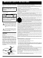
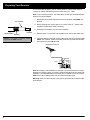
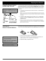
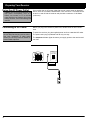
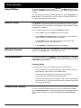
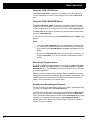
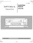
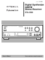
Cat. No. 31-3034 Digital Synthesize AM/FM Stereo Receiver STA-3500 VOLUME STA-3500 DIGITAL SYNTHESIZED AM/FM STEREO RECEIVER PHONO TUNER LD/DVD CD TAPE 1 VCR TAPE 2 MONITOR STAND BY POWER SUPER BASS MIN MEMORY PHONES CLASS STATION FM/AM TUNING BASS MAX TREBLE BALANCE SPEAKERS A B FM MONO OSR L Owner’s Manual R Please read before using this equipment. Introducing the Optimus STA-3500 Your Optimus STA-3500 Digital Synthesized AM/FM Stereo Receiver is the perfect control center for your audio/video system. It combines 100 watts-per-channel of clean power with modern styling. It provides connections for two tape decks, a turntable, a CD player, and one other audio source, such as audio from a digital video disk (DVD) player. You can also connect up to two pairs of speakers (not provided) to your receiver. Additional features include: Digital-Synthesized Tuner Precisely tunes to AM and FM stations. Automatic Tuning Lets you search for the next available FM station. 30 Memory Locations Let you store and recall the frequencies for up to 30 radio stations. Tape Monitoring Lets you listen to the actual recording as you record, if your tape deck has a tape-monitoring feature. Also lets you listen to a tape playing in TAPE 2 while TAPE 1 continues to record the program you selected. Built-In Protection Circuits Turn off the receiver to help prevent damage if a power surge or short circuit occurs. Remote Control Lets you use a single remote control for the receiver and other compatible components connected to the receiver. We recommend you record the receiver’s serial number here. The serial number is on the receiver’s back panel. Serial Number:_____________________________________________ 1996 Tandy Corporation. All Rights Reserved. Optimus is a registered trademark used by Tandy Corporation. RadioShack is a trademark used by Tandy Corporation. 2 IMPORTANT SAFETY INSTRUCTIONS This receiver is made and tested to meet exacting safety standards. It meets both UL and FCC requirements WARNING: TO REDUCE THE RISK OF FIRE OR ELECTRIC SHOCK, DO NOT EXPOSE THIS APPLIANCE TO RAIN OR MOISTURE. To prevent fire or shock hazard, do not expose this system to rain or moisture. CAUTION ! RISK OF ELECTRIC SHOCK. DO NOT OPEN. CAUTION: TO REDUCE THE RISK OF ELECTRIC SHOCK, DO NOT REMOVE COVER OR BACK. NO USER-SERVICEABLE PARTS INSIDE. REFER SERVICING TO QUALIFIED PERSONNEL. This symbol is intended to alert you to the presence of uninsulated dangerous voltage within the system’s enclosure that might be of sufficient magnitude to constitute a risk of electric shock. Do not open the system’s case. ! This symbol is intended to inform you that important operating and maintenance instructions are included in the literature accompanying this system. Careful attention is devoted to quality standards in the manufacture of your receiver, and safety is a major factor in its design. However, safety is also your responsibility. This section lists important information that will help you properly use and enjoy your receiver and accessories. Read all the included safety and operating instructions before using your receiver. Follow them closely, and retain them for future reference. Heed Warnings — Follow all warnings on the product and in the operating instructions. Cleaning — Unplug this product from the wall outlet before cleaning. Use only a damp cloth for cleaning. Do not use liquid or aerosol cleaners. Attachments — Do not use attachments/accessories not recommended by the product manufacturer, as they might create a hazard. Water and Moisture — Do not use this product near water (for example, near a bathtub, washbowl, kitchen sink, or laundry tub; in a wet basement; or near a swimming pool). Accessories — Do not place this product on an unstable cart, stand, tripod, bracket, or table. The product may fall, causing serious injury to a child or adult, and serious damage to the product. Use only with a cart, stand, tripod, bracket, or table recommended by the manufacturer or sold with the product. Follow the manufacturer's instructions for mounting, and use a recommended mounting accessory. Carts — Move the product on a cart carefully. Quick stops, excessive force, and uneven surfaces may cause the product/cart to overturn. Ventilation — Slots and openings in the cabinet provide ventilation, ensure reliable operation, and protect from overheating. Do not block or cover these openings, and do not place the product on a bed, sofa, rug, or other similar surface. Do not place the product in a built-in bookcase or rack unless it provides proper ventilation as specified by the manufacturer. Power Sources — Operate this product using only the power source indicated on its marking label. If you are not sure of your home's power type, consult your product dealer or local power company. Polarization — This product is equipped with a polarized AC line plug (a plug having one blade wider than the other). This plug will fit in the power outlet only one way. This is a safety feature. If you cannot insert the plug fully into the outlet, try reversing the plug. If the plug still doesn't fit, contact your electrician to replace your obsolete outlet. Do not defeat the safety purpose of the polarized plug. If you need an extension, use a polarized cord. Power-Cord Protection — Route power-supply cords so they are not likely to be walked on or pinched by items placed on or against them, paying particular attention to cords at plugs, convenience receptacles, and the point where they exit from the product. Lightning — For added protection for this product during a lightning storm, or when it is left unattended and unused for long periods of time, unplug it from the wall outlet and disconnect the antenna or cable system. This will prevent damage to the product due to lightning and power-line surges. Overloading — Do not overload wall outlets, extension cords, or integral convenience receptacles, as this can result in a risk of fire or electric shock. CAUTION Power Lines—Locate an outdoor antenna away from power lines. Nonuse Periods—Unplug the receiver’s power cord when you will not use it for extended periods. Outdoor Antenna Grounding—If an outside antenna or cable system is connected to the receiver, ground the antenna or cable system so as to provide some protection against voltage surges and built-up static charges. Article 810 of the National Electrical Code, ANSI/NFPA 80, provides information about proper grounding of the mast and supporting structure, grounding of the lead-in wire to an antenna discharge unit, size of grounding conductors, location of antennadischarge unit, connection to grounding electrodes, and requirements for the grounding electrode. See the example below. Objects and Liquids — Never push objects of any kind into this product through openings, as they may touch dangerous voltage points or short out parts that could result in a fire or electric shock. Never spill liquid of any kind on the product. Servicing — Do not attempt to service this product yourself, as opening or removing covers may expose you to dangerous voltage or other hazards. Refer all servicing to qualified service personnel. Damage Requiring Service — Unplug this product from the wall outlet and refer servicing to qualified service personnel under the following conditions: • When the power-supply cord or plug is damaged. • If liquid has been spilled or objects have fallen into the product. • If the product has been exposed to rain or water. • If the product does not operate normally by following the operating instructions. Adjust only those controls that are covered by the operating instructions, as an improper adjustment of other controls may result in damage and will often require extensive work by a qualified technician to restore the product to normal operation. • If the product has been dropped or damaged in any way. • When the product exhibits a distinct change in performance. Antenna Lead-In Wire Ground Clamp Electric Service Equipment Antenna Discharge Unit (NEC Section 810-20) Grounding Conductors (NEC Section 810-21) Grounding Clamps NEC -- National Electrical Code Power Service Grounding Electrode System (NEC Article 250, Part H) Replacement Parts — When replacement parts are required, be sure the service technician uses replacement parts specified by the manufacturer or having the same characteristics as the original part. Unauthorized substitutions may result in fire, electric shock, or other hazards. Safety Check — Upon completion of service or repairs to this product, ask the service technician to perform safety checks to determine that the product is in proper operating condition. Wall or Ceiling Mount — The product should be mounted to a wall or ceiling only as recommended by the manufacturer. Heat — The product should be situated away from heat sources such as radiators, heat registers, stoves, or other products (including amplifiers) that produce heat. 3 Contents Preparing Your Receiver . . . . . . . . . . . . . . . . . . . . . . . . . . . . . . . . . . . . . . . . . . . . . . . . . . . . . . . . . . . . . . . . . . . . . . . . . . . . . 5 Positioning Speakers . . . . . . . . . . . . . . . . . . . . . . . . . . . . . . . . . . . . . . . . . . . . . . . . . . . . . . . . . . . . . . . . . . . . . . . . . . . 5 Connecting Speakers. . . . . . . . . . . . . . . . . . . . . . . . . . . . . . . . . . . . . . . . . . . . . . . . . . . . . . . . . . . . . . . . . . . . . . . . . . . 6 Connecting Program Sources . . . . . . . . . . . . . . . . . . . . . . . . . . . . . . . . . . . . . . . . . . . . . . . . . . . . . . . . . . . . . . . . . . . . .8 Connecting the Antennas . . . . . . . . . . . . . . . . . . . . . . . . . . . . . . . . . . . . . . . . . . . . . . . . . . . . . . . . . . . . . . . . . . . . . . . .9 Using One Remote Control for More Than One Unit . . . . . . . . . . . . . . . . . . . . . . . . . . . . . . . . . . . . . . . . . . . . . . . . . . 11 Installing the Remote Control’s Batteries . . . . . . . . . . . . . . . . . . . . . . . . . . . . . . . . . . . . . . . . . . . . . . . . . . . . . . . . . . . 11 Using the AC Power Outlet . . . . . . . . . . . . . . . . . . . . . . . . . . . . . . . . . . . . . . . . . . . . . . . . . . . . . . . . . . . . . . . . . . . . . . 12 Connecting to AC Power . . . . . . . . . . . . . . . . . . . . . . . . . . . . . . . . . . . . . . . . . . . . . . . . . . . . . . . . . . . . . . . . . . . . . . . .12 Basic Operation . . . . . . . . . . . . . . . . . . . . . . . . . . . . . . . . . . . . . . . . . . . . . . . . . . . . . . . . . . . . . . . . . . . . . . . . . . . . . . . . . . . .13 Tuning the Radio . . . . . . . . . . . . . . . . . . . . . . . . . . . . . . . . . . . . . . . . . . . . . . . . . . . . . . . . . . . . . . . . . . . . . . . . . . . . . .14 Using FM Mono . . . . . . . . . . . . . . . . . . . . . . . . . . . . . . . . . . . . . . . . . . . . . . . . . . . . . . . . . . . . . . . . . . . . . . . . . . . . . . . 15 Balance Control . . . . . . . . . . . . . . . . . . . . . . . . . . . . . . . . . . . . . . . . . . . . . . . . . . . . . . . . . . . . . . . . . . . . . . . . . . . . . . 15 Muting the Receiver . . . . . . . . . . . . . . . . . . . . . . . . . . . . . . . . . . . . . . . . . . . . . . . . . . . . . . . . . . . . . . . . . . . . . . . . . . . 15 Using Headphones . . . . . . . . . . . . . . . . . . . . . . . . . . . . . . . . . . . . . . . . . . . . . . . . . . . . . . . . . . . . . . . . . . . . . . . . . . . . 15 Cassette Deck Features . . . . . . . . . . . . . . . . . . . . . . . . . . . . . . . . . . . . . . . . . . . . . . . . . . . . . . . . . . . . . . . . . . . . . . . .15 Using the Remote Control . . . . . . . . . . . . . . . . . . . . . . . . . . . . . . . . . . . . . . . . . . . . . . . . . . . . . . . . . . . . . . . . . . . . . . . . . . . . 18 Troubleshooting . . . . . . . . . . . . . . . . . . . . . . . . . . . . . . . . . . . . . . . . . . . . . . . . . . . . . . . . . . . . . . . . . . . . . . . . . . . . . . . . . . . .20 Care and Maintenance . . . . . . . . . . . . . . . . . . . . . . . . . . . . . . . . . . . . . . . . . . . . . . . . . . . . . . . . . . . . . . . . . . . . . . . . . . . . . . . 21 The FCC Wants You to Know . . . . . . . . . . . . . . . . . . . . . . . . . . . . . . . . . . . . . . . . . . . . . . . . . . . . . . . . . . . . . . . . . . . . . . . . . 22 Specifications . . . . . . . . . . . . . . . . . . . . . . . . . . . . . . . . . . . . . . . . . . . . . . . . . . . . . . . . . . . . . . . . . . . . . . . . . . . . . . . . . . . . . . 23 Index to Features by Control Name . . . . . . . . . . . . . . . . . . . . . . . . . . . . . . . . . . . . . . . . . . . . . . . . . . . . . . . . . . . . . . . . . . . . 25 4 Preparing Your Receiver Caution: Make all the necessary connections before you plug in or turn on the receiver. Positioning Speakers a L R Halfway Point Between Speake b a=b Person in Listening Area Where you place your speakers can make a noticeable difference in your system’s sound. The guidelines in this section will help you choose the best locations. After you use your receiver for a while, you might want to try different locations for your speakers. Bass response depends largely on speaker location. For strong bass, place the speakers in the corners of the room. If you want even stronger bass, place the speakers directly on the floor. If the bass is too strong, move the speakers slightly away from the corners of the room, or raise them 6 to 18 inches off the floor. You can buy speaker stands at your local RadioShack store. The distance between the speakers should be about the same as the distance between the normal listening point and the point halfway between the speakers. If you place the speakers too close together, you reduce the stereo separation. If you place them too far apart, you reduce the bass effect and create a hole in the middle of the sound. Most speakers have a tweeter dispersion angle of about 60 degrees. Ideally, your listening position should be just inside the overlap area of the tweeter dispersion. You can angle the speakers toward you for better stereo effect. 5 Preparing Your Receiver Connecting Speakers Follow these guidelines when you select and connect speakers. • Only connect speakers that are rated at between 8 and 16 Ohms. • Be sure you properly connect all speakers. • Do not connect two pairs of speakers to a single set of terminals (A or B) at the same time. When you use two pairs of speakers, connect one set to Speakers A and one set to Speakers B. • Realistic, Optimus, and other highquality speakers have color-coded speaker terminals (red for positive polarity and black for negative polarity). Use these color-coded terminals as a guide to help you properly connect the speakers to the receiver. • Use 16-gauge (or larger) speaker wire for all speaker connections, and consider possible speaker locations before you decide how much speaker wire you need. Preparing the Speaker Wires Speaker wire consists of two conductors (individual wires) encased in insulation and is usually color-coded or marked with a ridge along one side so you can identify each conductor. Use these markings as a guide to help you properly connect the speakers to your receiver. Follow these steps to prepare the speaker wires. WireStrands Strand Wire Conductor Speaker Wire WireWire Strands Strands Conductor Conductor 1. Cut the speaker wires to the necessary length. 2. Separate the wires about 4 inches on each end. 3. Using a wire stripper, carefully strip about 3/4 inch of insulation from the end of each conductor. 4. Twist the end of each conductor to secure any loose wire strands. 6 Preparing Your Receiver Connecting the A and B Speakers Notes: • Be sure you connect the receiver’s right and left positive (+) and negative (–) terminals to the speaker’s corresponding right and left positive (+) and negative (–) terminals. Follow these steps to connect the right speaker to the receiver’s right A SPEAKERS terminals. 1. Press the receiver’s A SPEAKERS R (+) red lever and insert the ridged or color-coded conductor’s end into the small hole. Pull back the lever to secure the conductor. • Fully insert the speaker wires to ensure a good connection. Leave extra wire at the back of the receiver so you do not disconnect the wires when you move the receiver. 2. Press the receiver’s A SPEAKERS R (–) black lever and insert the other conductor’s end into the small hole. Pull back the lever to secure the conductor. Caution: To prevent a short circuit, twist the end of each conductor to be sure that stray speaker wire strands do not touch other speaker terminals or any other receiver terminals. 3. Connect the ridged or color-coded conductor’s loose end to the right speaker’s positive (+) terminal. 4. Connect the remaining loose conductor to the right speaker’s negative (–) terminal. Repeat Steps 1 through 4 to connect the left speaker to the receiver’s A SPEAKERS L terminals. Repeat this entire process to connect a second pair of speakers to the B SPEAKERS terminals. SPEAKERS R L A A B B R L B Speakers Left A Speakers Left 7 Preparing Your Receiver Connecting Program Sources You can connect up to five external program sources to your receiver. GND IN REC PLAY REC PLAY IN IN L L L R OUT R TAPE2 MONITOR PHONO TAPE 1 /VCR R LD /DVD CD CONTROL L R R L L L L REC L PLAY OUTPUT R REC INPUT R OUT PUT L R REC INPUT LINE PLAY PLAY OUTPUT L LINE PLAY R L R R L L R R L R R L R L R REC OUT PUT L L R R CD Turntable Cassette Deck Cassette Deck LD/DVD Player CD Player Connecting a Turntable Note: Use shielded audio cables with phono connectors for all audio connections. Connect a turntable with a magnetic cartridge only. Some older turntables use a ceramic-type cartridge that does not work with this system. Connect the turntable’s left and right cables to the receiver’s left and right PHONO jacks. Then connect the turntable’s ground wire to the receiver’s GND terminal. Connecting Cassette Deck(s) Note: If you place the cassette deck directly above, below, or to the left of the receiver, the receiver could interfere with the cassette deck’s operation. If possible, position the cassette deck to the right of the receiver or locate it away from the receiver. You can connect cassette decks to the TAPE 1/VCR and the TAPE 2 MONITOR jacks. Connect the cassette deck’s output jacks to the TAPE 1/VCR PLAY or TAPE 2 MONITOR PLAY jacks, and connect the cassette deck’s input jacks to TAPE 1/VCR REC (audio) or TAPE 2 MONITOR REC jacks. Connecting a CD Player To connect a CD player to the receiver, connect the CD player’s left and right output jacks to the receiver’s L and R CD IN jacks. Connecting Another Audio Source Connect the audio outputs of another audio source, such as the audio from a laser disc player, TV, VCR, or CD player, to the LD/DVD IN L and R jacks. 8 Preparing Your Receiver Connecting the Antennas Warning: To prevent injury, read and follow all cautions and warnings that accompany the outdoor antenna. In many cities, the supplied indoor AM loop and FM antennas provide adequate reception. AM Antennas Assemble the included antenna’s base by swinging the base in the direction of the arrow and inserting the antenna’s bottom tabs into the base’s slot. Then attach the antenna wires to the AM LOOP ANTENNA and GND terminals. Place the antenna on a flat surface and rotate it for the best AM reception. If the receiver is in a rack or on a shelf and there is no room for the AM loop antenna, use two screws (not supplied) to mount the base on the wall or another location as shown. Notes: • Keep the AM loop antenna connected even when you use another indoor antenna or an outdoor AM antenna. • Ensure the antenna does not touch the receiver or other metal objects. • Do not place the antenna near a CD player, a personal computer, or a TV set • If the wire between your AM loop antenna and receiver is too short, you can add extra wire, available at your local RadioShack store. AM Loop Antenna FM UNBAL 75 GND AM LOOP ANTENNA GND You can also use a RadioShack shortwave antenna kit (Cat. No. 278758), which makes an excellent outdoor AM antenna. Connect the outdoor AM antenna wire to the receiver’s AM terminal, as shown. ANTENNA door AM Antenna AM LOOP FM ANTENNA UNBAL 75 GND GND FM Antennas Connect the supplied FM antenna to the FM UNBAL 75Ω terminal and extend it as shown. FM Antenna FM UNBAL GND 75 AM LOOP ANTENNA GND ANTENNA Note: For the best results, use 75-ohm coaxial cable to connect an outdoor antenna to the receiver. For better FM reception, you can also use a rabbit-ear TV antenna (for indoor use only) or an outdoor VHF TV antenna. To connect the TV antenna to the receiver, you need a VHF/UHF/FM splitter (not included). RadioShack stores carry a full line of quality outdoor antennas and antenna connection accessories. 9 Preparing Your Receiver For the best radio reception, use an outdoor antenna. Follow these steps to connect an outdoor FM antenna to the receiver using 75Ω cable. Note: If your antenna has 300Ω twin-lead cable, consult your local RadioShack store for the correct adapter. 1. Disconnect the supplied FM antenna from the receiver’s FM UNBAL 75Ω terminal. Inner Insulation 2. With a stripping tool, remove about 1 1/2 inches of the 75Ω cable’s outer insulation to expose the cable’s shielding. 3. Fold back the insulation from the inner insulation. Center Wir Outer Insulation Shielding Caution: The cable’s shielding should only touch the GND terminal. 4. Remove about 1 inch of the inner insulation from around the center wire. 5. Pull the shielding to one side. Connect the center wire to the receiver’s FM UNBAL 75Ω terminal. Twist the shielding to secure any loose wire strands, and connect it to the GND terminal. FM Outdoor Antenna Shielded Core 75 FM UNBAL GND AM LOOP ANTENNA GND ANTENNA Note: Grounding is not necessary for reception, but we recommend it to avoid damage from lightning when you use an outdoor FM antenna and for better FM reception. Use a separate piece of thick polyvinyl insulated wire to connect the GND terminal to an earth ground such as a metal cold-water pipe. Warning: Never connect a wire to a gas pipe for grounding since sparks might ignite the gas. 10 Preparing Your Receiver Using One Remote Control for More than One Unit Note: When you plug the cable into a component’s CONTROL IN jack, that component’s remote sensor does not function. CONTROL IN OUT OUT If you also have an Optimus professional series CD player, VCR, or cassette deck with the OSR mark, you can connect its CONTROL IN jack to the receiver so you can control all of your equipment with a single remote control. You can also use the other component’s remote control by pointing it at the receiver’s front panel. 1. Connect each component to the receiver as shown in “Connecting Program Sources.” Note: You must connect the audio cables between the receiver and the other audio accessory to use your receiver’s remote control to control the accessory. CONTROL Receiver Other Component with OSR Mark Remote Control To the CONTROL IN ja of Another Componen Having the OSR Mark Installing the Remote Control’s Batteries 2. Connect the cable supplied with the CD player, VCR, or cassette deck between the receiver’s CONTROL OUT jack and the other component’s CONTROL IN jack. 3. When you want to control more than one other component using the receiver’s remote control, daisy-chain the CONTROL OUT and CONTROL IN connections as shown. The remote control uses two AA batteries (not included). For the longest battery life, we recommend alkaline batteries (such as RadioShack Cat. No. 23-557). 1. Press and remove the battery compartment cover. Cautions: • Use only fresh batteries of the recommended size and type. 2. Place two fresh AA batteries in the compartment as indicated by the polarity symbols (+ and –) marked in the compartment. 3. Replace the battery compartment cover. • Always remove old or weak batteries. Batteries can leak chemicals that can damage electronic circuits. Note: If the remote’s range is reduced, replace the batteries immediately. 11 Preparing Your Receiver Using the AC Power Outlet Caution: Do not connect appliances with high power consumption, such as a heater, iron, monitor, or TV, to this AC outlet. Doing so can cause a risk of overheating and fire, and could damage the receiver. Connecting to AC Power Warning: To prevent electric shock, do not use this polarized plug with an extension cord, receptacle, or other outlet unless you can fully insert the blades to prevent blade exposure. Your receiver has an AC power outlet that you can use to power an electronic device, such as a turntable, cassette deck, VCR, and so on. This switched outlet turns on and off with the receiver and provides a maximum of 100 Watts (0.8A max). Before you plug in the receiver’s power cord, double check all other connections. To power the receiver, plug the supplied power cord into a standard AC outlet. The power cord’s plug is polarized and fits only one way. The STAND BY indicator lights whenever you supply power to the receiver and turn it off. CAUTION: DO NOT CONNECT TV SET OR MONITOR. SPEAKERS R L AC 120V 60HZ A A B B R L SWITCHED 100W MAX 0.8A MAX AC OUTLET 12 Basic Operation Warning: To prevent possible hearing loss, turn VOLUME to MIN before you turn on the receiver or change the program sources. After you turn on the receiver or change the program source, adjust VOLUME to a comfortable listening level. Note: The controls on the remote control work the same as the buttons on the receiver’s front panel. Follow these steps to use the receiver. 1. Press POWER to turn on the receiver’s power. It takes about 5 seconds to begin hearing sound. 2. Select the speakers. If you connected speakers only to the A (or B) SPEAKERS terminals, press SPEAKERS A (or B) to turn on only those speakers. Do not press both SPAKERS A and B. Doing so disconnects all speakers. If you connected speakers to both the A and B SPEAKERS terminals, do any of the following: Note: If you want to find out what a particular button or control is used for, see Page 18(for the remote control) or Page 25(for the front panel) to find the page where the button or control is described. • Press in SPEAKERS A or B to turn on either pair of speakers for a twospeaker stereo effect. • Press in SPEAKERS A and B to turn on both pairs of speakers for a four-speaker stereo effect. • Press SPEAKERS A and B to the out position to silence all speakers and listen privately with headphones (see “Using Headphones” on Page 15). 3. Select a program source. To tune to a radio station, see “Tuning the Radio” on Page 15. Note: If you select a source while TAPE 2 TAPE 2 flashes five times on the display, reminding you to disengage the TAPE 2 MONITOR function MONITOR is engaged, To listen to signals from the component connected to TAPE 2 MONITOR, press TAPE 2 MONITOR so TAPE 2 appears on the display. To listen to a source other than one connected to TAPE 2 MONITOR, be sure TAPE 2 does not show on the display. If necessary, press TAPE 2 MONITOR so TAPE 2 disappears. Then press TAPE 1/VCR, LD/DVD, CD, TUNER, or PHONO, or repeatedly press FUNCTION on the remote control, to display the desired program source. 4. Adjust VOLUME clockwise to increase the volume and counterclockwise to decrease it. Or, you can use VOLUME –/+ on the remote control. 5. Use the BASS and TREBLE controls to adjust the program’s tonal quality. To enhance the bass level, press SUPER BASS. 6. Adjust BALANCE to suit your listening preferences. See “Balance Control” on Page 14. 7. Press POWER to turn off the receiver. 13 Basic Operation Tuning the Radio Note: For weak signals, we recommend manual tuning. Your receiver offers three types of electronic tuning—manual, automatic, and memory. Manual and Automatic Tuning Follow these steps to manually or automatically tune to the stations. 1. Press TUNER. Then press FM/AM to select the desired band. The receiver tunes to and displays the frequency last selected in that band. 2. Press TUNING or once to move to the next higher or lower frequency. Or, press and hold down TUNING or to rapidly change frequencies. Release the button to stop. To search for the next higher or lower FM station, release TUNING or as soon as the frequency starts to change. The receiver searches up or down the FM band until it finds a strong station. Notes: • STEREO appears on the display when FM broadcasts are received in stereo and the receiver is not set to FM mono.TUNED appears on the display when you tune to a strong station. To find a weak FM station, press FM MONO until MONO appears. See “Using FM Mono” on Page 15. • If you press TUNING at the top of the frequency range or TUNING at the bottom of the frequency range, the display returns to the other end of the range. Memory Tuning Memory tuning lets you instantly tune to a stored frequency. You can store up to 30 AM or FM frequencies (10 frequencies in each of three classes) in the receiver’s memory. Follow these steps to store a station. 1. Press TUNER. Then press FM/AM to select the desired band. Notes: • If you store a frequency in a memory that already contains a frequency, you replace the previous frequency. • If your receiver is disconnected from AC power for several days, it loses all the stored frequencies. 2. Using either manual or automatic tuning, select the frequency you want to store. If desired, press FM MONO for FM monaural sound (see “Using FM Mono” on Page 16). This setting is stored in the memory. 3. Press MEMORY. MEMORY appears for 5 seconds. 4. While MEMORY is on the display, press CLASS until the class number you want (1-3) appears on the display. Then press STATION or until the station number you want appears on the display. Repeat these steps to store additional frequencies. Do not enter a frequency while the display flashes. To tune to a stored frequency, press CLASS so the desired class number appears on the display, then press STATION / to select the station. 14 Basic Operation Using FM Mono To receive FM stations in stereo, press FM MONO until MONO disappears from the display. STEREO appears on the display when you receive an FM broadcast in stereo. You can improve the reception of weak FM stations by pressing FM MONO until MONO appears. This reduces noise while you listen to a weak FM station, but you get monaural instead of stereo sound. Balance Control The BALANCE control lets you adjust the sound balance between the left and right speakers. If you properly position the speakers and your listening area is centered between them, the center control setting is usually best (see “Positioning Speakers” on Page 5). For an unusual speaker placement, adjust BALANCE as follows: 1. Select TUNER. Then press FM/AM to select the FM band. 2. Press FM MONO until MONO appears. The sound is monaural instead of stereo, so each speaker delivers the same output. 3. Turn BALANCE until you hear the sound coming equally from each speaker when you are in the listening area. 4. Press FM MONO until MONO disappears from the display. Muting the Receiver To temporarily mute the sound, press MUTING on the remote control. MUTING appears. Press MUTING again to restore the audio level. Using Headphones To listen with headphones (not supplied), insert the headphones’ 1/4-inch plug into the receiver’s front panel PHONES jack. To silence the speakers, set A and B SPEAKERS to the out position. Listening Safely To protect your hearing, note the following when using headphones. • Set the volume to its lowest setting before you begin listening. After you begin listening, adjust volume to a comfortable level. • Do not listen at extremely high volume levels. Extended highvolume listening can lead to permanent hearing loss. • Once you set the volume, do not increase it. Over time, your ears adapt to the volume level, so a volume level that does not cause discomfort might still damage your hearing. Cassette Deck Features You can connect two cassette decks to the receiver. Selecting either TAPE 1/ VCR or TAPE 2 MONITOR lets you hear the playback from the cassette deck you connected to the receiver’s corresponding (TAPE 1/VCR, TAPE 2 MONITOR) jacks. 15 Basic Operation Using the TAPE 1/VCR Button Press TAPE 1/VCR. TAPE 1 appears on the display. You hear the playback from the cassette deck or VCR you connected to the receiver’s TAPE 1/VCR jacks. Using the TAPE 2 MONITOR Button Press TAPE 2 MONITOR. TAPE 2 appears on the display along with the last program source you selected. You can hear playback or monitor a recording from the cassette deck you connected to the receiver’s TAPE 2 MONITOR jacks. The TAPE 2 REC jacks continue to output the previously selected source when you press TAPE 2 MONITOR. To return to the previous source, press TAPE 2 MONITOR again so TAPE 2 disappears. Notes: • If you press TAPE 2 MONITOR when that cassette deck is neither playing nor recording, the receiver mutes the current audio source. To hear the audio source, press TAPE 2 MONITOR until TAPE 2 disappears from the display. • Do not press TAPE 2 MONITOR while you are recording on the deck connected to TAPE 2 REC. If you do, the recording is interrupted for about 1 second. Recording a Program Source The receiver sends the audio program source you select— TAPE 1/VCR, TAPE 2 MONITOR , LD/DVD, CD, TUNER, PHONO —to the TAPE 1/VCR REC and TAPE 2 MONITOR REC jacks. The VOLUME control does not affect the level of the signal going to the tape decks. When you record a program source using the Tape 2 cassette deck, you hear the program source’s signal immediately after you record it onto the tape, if the cassette deck you connected has a three-head monitor function. (Be sure to read the owner’s manual for your cassette deck.) Simultaneous Recording and Playback You can record any non-tape program source on the Tape 1 cassette deck while you listen to a cassette tape using TAPE 2 MONITOR. Press the button for the desired program source (LD/DVD , CD, TUNER, PHONO), then press the record button on the cassette deck connected to TAPE 1/VCR. Tape 1 records the selected program source. Press TAPE 2 MONITOR, then start playback on the cassette deck connected to TAPE 2 MONITOR. TAPE 2 appears and you hear Tape 2 play back while Tape 1 continues to record the program source you selected. 16 Basic Operation Dubbing a Cassette Tape You can copy, or dub, a cassette tape from one cassette deck to another. You can use either deck as the playback or recording deck. However, if you want to monitor the cassette deck during dubbing, use the deck connected to the TAPE 1/VCR jacks as the source, and the deck you connected to the TAPE 2 MONITOR jacks as the recording deck. Then press TAPE 2 MONITOR until TAPE 2 appears on the display. See “Using the TAPE 2 MONITOR Button” on the previous page. 17 Using the Remote Control The remote control works up to a distance of about 23 feet, and within a 30degree angle on either side of the receiver. Point the control at the receiver’s front panel and press the desired button(s). Many buttons on the remote control work the same as buttons on the receiver’s front panel. Use these buttons exactly as you would use the corresponding buttons on the receiver. Receiver/Amplifier Section FUNC Selects a program source (Tape 1/VCR, LD/DVD, CD, tuner, or phono). Repeatedly press FUNC until the display shows your desired program source. See Page 13. – VOLUME + Adjusts the system’s volume. See Page 13. RECEIVER POWER Turns the receiver on and off. See Page 13. TAPE 2 MONITOR Switches the receiver to monitor the source connected to the TAPE 2 MONITOR jacks. See Page 16. S. BASS Press to enhance bass sound. MUTING Silences the receiver. Press again to restore the sound to its previous level. See Page 14. CD BEST ASMS DECK1 DISC DECK2 TAPE TUNING STATION TUNER FM MONO FM/AM CLASS S.BASS TAPE2 MONITOR FUNC POWER RECEIVER CD MUTING Receive Section VOLUME TAPE STA-3500 STEREO RECEIVER SYSTEM REMOTE OSR STATION Press to move the next higher or lower station in memory. CLASS Press to select the class of the station in memory FM MONO Press to disable the FM stereo mode to improve reception of weaker FM stations. TUNING Manual Tuning: Press once to select the next higher or lower frequency. Or, press and hold down to rapidly change frequencies. Automatic Tuning (FM Only): To search for the next lower or higher station, release TUNING when the frequency starts to change. The receiver searches up or down the band until it finds a strong station. FM/AM 18 Press to switch between AM and FM bands. Using the Remote Control CD Player Section Note: You must connect the CD player both to your receiver’s CONTROL OUT and audio jacks for these functions to work. CD POWER | ASMS Turns the CD player on and off (only for CD players having the CONTROL IN/OUT feature). | DISC SELECT Selects discs in a multi-play CD changer. Note: Some CD players might function with DISC SELECT. CD BEST ASMS DECK1 Returns to the beginning of the current track or advances to the next track. DISC CD Player Section Plays the CD. DECK2 Stops playback. Tape Sectio TAPE Press to temporarily stop play. Press again to resume. TUNING STATION TUNER FM MONO FM/AM CLASS S.BASS TAPE2 MONITOR FUNC POWER RECEIVER CD MUTING BEST With a CD changer that has the BEST track memory function, such as an Optimus Professional Series CD-8200/8300/ 8400, press to select and play your favorite CD tracks. VOLUME TAPE STA-3500 STEREO RECEIVER SYSTEM REMOTE OSR Cassette Deck Section Before operation, select TAPE 2 MONITOR or TAPE1/VCR. Note: You must connect the cassette deck both to your receiver’s CONTROL OUT and audio jacks for these functions to work. Press to start normal play. Press to play the reverse side of an auto-reverse cassette deck. Press to cancel the current function. Press to temporarily stop playback/recording. Press again to resume. and Lets you quickly locate and play the beginning of recorded material during play. When the tape is stopped, lets you rapidly search forward or backward to locate a specific section of the tape. DECK 1/DECK 2 Selects Deck 1 or Deck 2 when you use a dual cassette deck. When you use a single cassette deck, press DECK 2. TAPE POWER Turns the cassette deck on and off. Note: TAPE POWER does not work with all Optimus Professional Series cassette decks. 19 Troubleshooting If the receiver is not working as it should, the following suggestions might help. If you follow the suggestions in this chart and the receiver still does not work properly, contact your local RadioShack store for assistance. Problem Cause Solution Power does not turn on. • Power cord is disconnected. • Plug in the power cord. No sound. • Incorrect connections. • Check and correct the connections. • The mute function is activated. • Press MUTING. • The volume is turned down. • Turn up the volume. • Speaker wires are disconnected. • Connect the speaker wires. • Neither set of speakers is selected. • Press in SPEAKERS A or B. • Both SPEAKERS A and B are pressed when only one set of speakers is connected. • Press SPEAKERS button again for the terminals that have no speakers. • TAPE 2 MONITOR is selected. • Press TAPE 2 MONITOR again. • One of the speaker wires or input cord is disconnected. • Check all connections. • BALANCE is set too far to one side. • Set BALANCE to the center position. • Station not correctly tuned. • Tune to a stronger station. • Antenna not connected. • Connect the antenna. • FM antenna still coiled or is not pointing in the correct direction. • Stretch both ends of the antenna taut and reposition the antenna. • AM loop antenna not pointing in the correct direction. • Adjust the AM loop antenna. • Noise is coming from another electrical appliance. • Try using an AC line noise filter to reduce the noise. Tuning does not automatically stop when searching for FM stations. • Stations are too weak. • Use a better antenna. Remote control does not work. • Batteries are dead or missing. • Install fresh batteries. • Poor angle or too great a distance from the remote sensor window. • Use within 23 feet and within a 30degree angle of the remote sensor window. • There is an obstacle between you and the remote sensor window. • Change your position or remove the obstacle. • For CD players and cassette decks, the remote control cord is not connected. • Connect the remote control cord. • A fluorescent light is shining on the remote sensor window. • Turn off the light. • Cassette deck or CD changer not compatible. • The feature only works with Optimus Professional Series components. • Control cable is not plugged in. • Properly connect the control cable. • Audio cables are not plugged in. • Properly connect the audio cables. Sound is produced from only one speaker. High noise level. Remote does not control cassette deck or CD player. 20 Care and Maintenance Your STA-3500 Digital Synthesized AM/FM Stereo Receiver is an example of superior design and craftsmanship. The following suggestions will help you care for the receiver so you can enjoy it for years. Keep the receiver dry. If it gets wet, wipe it dry immediately. Liquids can contain minerals that can corrode the electronic circuits. Handle the receiver gently and carefully. Dropping it can damage its circuit boards and can cause the receiver to work improperly. Use and store the receiver only in normal temperature environments. Temperature extremes can shorten the life of electronic devices, damage batteries, and distort or melt plastic parts. Keep the receiver away from dust and dirt, which can cause premature wear of parts. CLEANER Wipe the receiver with a damp cloth occasionally to keep it looking new. Do not use harsh chemicals, cleaning solvents, or strong detergents to clean the receiver. Use only fresh batteries of the recommended size and type in the remote control. Always remove old or weak batteries. They can leak chemicals that can destroy electronic circuits. Modifying or tampering with your receiver’s internal components can cause a malfunction and might invalidate the receiver’s warranty and void your FCC authorization to operate it. If the receiver is not operating as it should, take it to your local RadioShack store for assistance. 21 The FCC Wants You To Know Your receiver might cause radio or TV interference even when it is operating properly. To determine whether your receiver is causing the interference, turn off your receiver. If the interference goes away, your receiver is causing it. Try to eliminate the interference by: • Moving your radio or TV away from the receiver • Connecting your receiver to an outlet that is on a different electrical circuit from the radio or TV • Contacting your local RadioShack store for help If you cannot eliminate the interference, the FCC requires that you stop using your receiver. 22 Specifications Amplifier Front Channel Average Power Output . . . . . . . . . . . . . . . . . . . . . . . . . . . . . . . . . . . . . . . . 100 Watts per Channel into 8 Ohms From 40 to 20,000 Hz, With No More than 0.9% Total Harmonic Distortion Measured Pursuant to the Federal Trade Commission’s Trade Regulation Rule on Amplifier Output Power Claims Input Sensitivity/Impedance Phono . . . . . . . . . . . . . . . . . . . . . . . . . . . . . . . . . . . . . . . . . . . . . . . . . . . . . . . . . . . . . . . . . . . . . . 2.8 mV/47 kOhms CD, LD/DVD, TAPE 1/VCR, Tape 2 Monitor . . . . . . . . . . . . . . . . . . . . . . . . . . . . . . . . . . . . . . . 200 mV/47 kOhms Phono Overload Level (0.1% THD, 1 kHz) . . . . . . . . . . . . . . . . . . . . . . . . . . . . . . . . . . . . . . . . . . . . . . . . . . . . . . . . . . . 100 mV Frequency Response Phono . . . . . . . . . . . . . . . . . . . . . . . . . . . . . . . . . . . . . . . . . . . . . . . . . . . . . . . . . . . . . . 20 Hz to 20,000 Hz ±0.5 dB CD, LD/DVD, TAPE 1/VCR, TAPE 2 Monitor . . . . . . . . . . . . . . . . . . . . . . . . . . . . . . 5 Hz to 100,000 Hz +0/–3.0 dB Signal-to-Noise Ratio (IHF, Short Circuited, A Network) Phono . . . . . . . . . . . . . . . . . . . . . . . . . . . . . . . . . . . . . . . . . . . . . . . . . . . . . . . . . . . . . . . . . . . . . . . . . . . . . . . . 72 dB CD, LD/DVD, TAPE 1/VCR, Tape 2 Monitor . . . . . . . . . . . . . . . . . . . . . . . . . . . . . . . . . . . . . . . . . . . . . . . . . . 96 dB Signal-to-Noise Ratio (EIA, at 1 Watt, 1 kHz) Phono . . . . . . . . . . . . . . . . . . . . . . . . . . . . . . . . . . . . . . . . . . . . . . . . . . . . . . . . . . . . . . . . . . . . . . . . . . . . . . . . 77 dB CD, LD/DVD, TAPE 1/VCR, Tape 2 Monitor . . . . . . . . . . . . . . . . . . . . . . . . . . . . . . . . . . . . . . . . . . . . . . . . . . 80 dB FM Tuner Frequency Range . . . . . . . . . . . . . . . . . . . . . . . . . . . . . . . . . . . . . . . . . . . . . . . . . . . . . . . . . . . . . . . . . . . . . . . 87.5 to 108 MHz Usable Sensitivity . . . . . . . . . . . . . . . . . . . . . . . . . . . . . . . . . . . . . . . . . . . . . . . . . . . . . . Mono: 11.2 dBf, IHF (1.0 µV/75 Ohms) 50 dB Quieting Sensitivity Mono . . . . . . . . . . . . . . . . . . . . . . . . . . . . . . . . . . . . . . . . . . . . . . . . . . . . . . . . . . . . . . . 16.8 dBf (1.9 µV/75 Ohms) Stereo . . . . . . . . . . . . . . . . . . . . . . . . . . . . . . . . . . . . . . . . . . . . . . . . . . . . . . . . . . . . . . 38.6 dBf (23.3 µV/75 Ohms) Signal-to-Noise Ratio Mono . . . . . . . . . . . . . . . . . . . . . . . . . . . . . . . . . . . . . . . . . . . . . . . . . . . . . . . . . . . . . . . . . . . . . . . 76 dB (at 85 dBf) Stereo . . . . . . . . . . . . . . . . . . . . . . . . . . . . . . . . . . . . . . . . . . . . . . . . . . . . . . . . . . . . . . . . . . . . . . . 72 dB (at 85 dBf) Distortion Stereo . . . . . . . . . . . . . . . . . . . . . . . . . . . . . . . . . . . . . . . . . . . . . . . . . . . . . . . . . . . . . . . . . . . . . . . . . . . 0.5% (1 kHz) Alternate Channel Selectivity . . . . . . . . . . . . . . . . . . . . . . . . . . . . . . . . . . . . . . . . . . . . . . . . . . . . . . . . . . . . . . . 60 dB (400 kHz) Stereo Separation . . . . . . . . . . . . . . . . . . . . . . . . . . . . . . . . . . . . . . . . . . . . . . . . . . . . . . . . . . . . . . . . . . . . . . . . . 40 dB (1 kHz) Frequency Response . . . . . . . . . . . . . . . . . . . . . . . . . . . . . . . . . . . . . . . . . . . . . . . . . . . . . . . . . . . . . . 30 Hz to 15 kHz (±1 dB) Antenna Input . . . . . . . . . . . . . . . . . . . . . . . . . . . . . . . . . . . . . . . . . . . . . . . . . . . . . . . . . . . . . . . . . . . . . . 75 Ohms Unbalanced AM Tuner Frequency Range . . . . . . . . . . . . . . . . . . . . . . . . . . . . . . . . . . . . . . . . . . . . . . . . . . . . . . . . . . . . . . . . . . . . . . . 530 to 1700 kHz Sensitivity (IHF, Loop Antenna) . . . . . . . . . . . . . . . . . . . . . . . . . . . . . . . . . . . . . . . . . . . . . . . . . . . . . . . . . . . . . . . . . . . 350 µV/m Selectivity . . . . . . . . . . . . . . . . . . . . . . . . . . . . . . . . . . . . . . . . . . . . . . . . . . . . . . . . . . . . . . . . . . . . . . . . . . . . . . . . . . . . . . 25 dB Signal-to-Noise Ratio . . . . . . . . . . . . . . . . . . . . . . . . . . . . . . . . . . . . . . . . . . . . . . . . . . . . . . . . . . . . . . . . . . . . . . . . . . . . . . 50 dB 23 Specifications General Power Requirements . . . . . . . . . . . . . . . . . . . . . . . . . . . . . . . . . . . . . . . . . . . . . . . . . . . . . . . . . . . . . . . . . . 120 Volts AC, 60 Hz Power Consumption . . . . . . . . . . . . . . . . . . . . . . . . . . . . . . . . . . . . . . . . . . . . . . . . . . . . . . . . . . . . . . . . . . . . . . . 190 Watts (UL) AC Outlet Ratings Switched . . . . . . . . . . . . . . . . . . . . . . . . . . . . . . . . . . . . . . . . . . . . . . . . . . . . 100 Watts (0.8 Amps) Maximum Dimensions (HWD) . . . . . . . . . . . . . . . . . . . . . . . . . . . . . . . . . . . . . . . . . . . . . . . . . . . . . . . . . . . . . . 5 1/2 × 16 9/16 × 11 3/4 Inches (140 × 420 × 298mm) Weight . . . . . . . . . . . . . . . . . . . . . . . . . . . . . . . . . . . . . . . . . . . . . . . . . . . . . . . . . . . . . . . . . . . . . . . . . . . . . . 14 lbs, 6oz (6.6 kg) Specifications are typical; individual units might vary. Specifications are subject to change and improvement without notice. 24 Index to Features by Control Name This table lists the control and indicator names found on the front of your receiver, along with the page number where the control or indicator is discussed. To find a description for the buttons on the remote control, see “Using the Remote Control” on Page 18. Control Page BALANCE 15 BASS 13 CD 13 CLASS 14 FM MONO 15 FM/AM 14 LD/DVD 13 MEMORY 14 MUTING 16 PHONES 16 PHONO 13 POWER 13 SPEAKERS A and B 13 STATION 14 STANDBY 12 SUPER BASS 13 TAPE 1/VCR 13, 16 TAPE 2 MONITOR 13, 16 TREBLE 13 TUNER 13 TUNING 14 VOLUME 13 25 Notes 26 27 RadioShack Limited Warranty This product is warranted against defects for 2 years from date of purchase from RadioShack company-owned stores and authorized RadioShack franchisees and dealers. Within this period, we will repair it without charge for parts and labor. Simply bring your RadioShack sales slip as proof of purchase date to any RadioShack store. Warranty does not cover transportation costs. Nor does it cover a product subjected to misuse or accidental damage. EXCEPT AS PROVIDED HEREIN, RADIOSHACK MAKES NO EXPRESS WARRANTIES AND ANY IMPLIED WARRANTIES ARE LIMITED IN DURATION TO THE DURATION OF THE WRITTEN LIMITED WARRANTIES CONTAINED HEREIN. Some states do not permit limitation or exclusion of implied warranties; therefore, the aforesaid limitation(s) or exclusion(s) may not apply to the purchaser. This warranty gives you specific legal rights and you may also have other rights which vary from state to state. We Service What We Sell 10/95 RadioShack A Division of Tandy Corporation Fort Worth, Texas 76102 7A6 <ARB1484-A> Printed in Japan