1
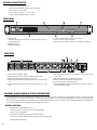
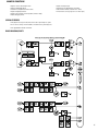
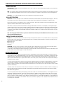
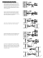
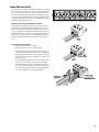
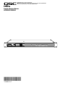
1675 MacArthur Blvd., Costa Mesa, CA, 92626 USA
Main Number (714) 754-6175 Sales & Marketing (714) 957-7100 or toll free (USA only) (800) 854-4079
Customer Service(714) 957-7150 or toll free (USA only) (800) 772-2834
CM16a
Amplifier Network Monitor
HARDWARE MANUAL
*TD-000086-00*
TD-000086-00 Rev.D
IMPORTANT SAFETY PRECAUTIONS & EXPLANATION OF SYMBOLS
The lightning flash with arrowhead symbol within an equilateral triangle is intended to alert the user to
the presence of uninsulated “dangerous” voltage within the product’s enclosure that may be of sufficient
magnitude to constitute a risk of electric shock to humans.
The exclamation point within an equilateral triangle is intended to alert the user to the presence of
important operating and maintenance (servicing) instructions in this manual.
SAFEGAURDS
Electrical energy can perform many useful functions. This unit has been engineered and manufactured to
assure your personal safety. Improper use can result in potential electrical shock or fire hazards. In order
not to defeat the safeguards, observe the following instructions for its installation, use and servicing.
CAUTION: To reduce the risk of electric shock, do not remove the cover. No user-serviceable parts inside.
Refer servicing to qualified service personnel.
WARNING: To prevent fire or electric shock, do not expose this equipment to rain or moisture.
1- Maximum operating ambient temperature is 50°C (122°F).
2- Never restrict airflow through the device fan or vents. Please insure that the air intake and
exhaust vents are unobstructed.
3- When installing equipment into rack, distribute the units evenly. Otherwise, hazardous conditions
could be created by an uneven weight distribution.
4- Connect the unit only to a properly rated supply circuit. The CM16a is suitable for connection to
100 - 240 VAC, 47 - 440 hertz, with no special considerations other than the appropriate IEC power
cord.
5- Reliable Earthing (Grounding) of rack-mounted equipment should be maintained.
FCC INTERFERENCE STATEMENT
NOTE: This equipment has been tested and found to comply with the limits for a Class A digital device, pursuant to
Part 15 of the FCC Rules. These limits are designed to provide reasonable protection against harmful interference in a
commercial installation. This equipment generates, uses, and can radiate radio frequency energy and, if not installed
and used in accordance with the instructions, may cause harmful interference to radio communications. Operation of
this equipment in a residential area is likely to cause harmful interference, in which case the user will be required to
correct the interference at his or her own expense.
© Copyright 2004, 2007 QSC Audio Products, LLC QSC® is a registered trademark of QSC Audio Products, LLC “QSC” and the QSC logo are registered with the U.S. Patent and Trademark Office. All trademarks are the property of their respective owners.
2
INTRODUCTION- OVERVIEW
The QSC CM16a Amplifier Network Monitor provides powerful amplifier management and zone paging capability in a QSControl networked audio
system using Ethernet networking technology to communicate with the host computer/system controller.
The host computer uses the QSControl application software to operate the networked audio system, including the CM16a’s and their amplifiers. The
software operates on the Microsoft Windows NT® version 4.0 operating system and can be customized using Microsoft® Visual Basic Professional
Edition.
This manual outlines the capabilities of the CM16a as well as its installation and connections. The operation of the CM16a is accomplished using
QSC’s QSControl software. Note that not all hardware features may be supported by the current software revision. Please refer to the software’s
documentation & help file for information regarding software features, usage and functions.
Each CM16a performs control and monitoring functions for up to 16 amplifier channels. This could be up to eight 2-channel or four 4-channel amplifiers (or some combination of these) at the time this document was printed. The amplifiers supported by the CM16a are the PowerLight, PL2, PL2A,
DCA, and CX series of QSC amplifiers that have a built-in DataPort. Models that do not have a built-in DataPort or models that have a DP-1 option or
“V2” DataPort (such as the EX, MXa, & ISA series) are NOT supported by the CM16a.
The DataPort connections are made with ordinary VGA computer monitor-type cables (HD-15 male-to-male). These cables are the same type that are
used on personal computer systems to connect the monitor to the computer. This allows you to use commonly available cabling for interconnecting
amplifiers to the CM16a. Each DataPort connection supports the control and monitoring functions for two audio channels. When using the CM16a
with amplifiers that have more than two channels (such as the 4 channel cinema amplifiers) additional DataPort connections are required.
The CM16a is a control and monitoring device that relies on software to do its job. The functions and capabilities provided in the design of the
CM16a can only be realized with proper software implementation. Keep in mind that this manual’s intent is to outline these capabilities and provide
a reference for properly installing and interconnecting the CM16a to the networked system’s host computer, the audio inputs and the amplifiers to be
controlled and monitored. A thorough knowledge of the control software’s features and operation will provide the best possible results for the end
user.
From all of us at QSC Audio Products, thank you for your purchase.
Note: PL2A amplifiers have programmable filters and crossovers. This makes gain “reporting” to the host unreliable as the
frequency content relates directly to reported output levels. Since the output level is used to calculate gain, it is not possible
to guarantee accurate gain reporting when the PL2A is set for any of its various frequency boost/cut/crossover modes.
WARNING
While QSC has endeavored to develop and produce the most dependable and robust ‘network’ audio product for your use,
due to the myriad of network situations and equipment that may be encountered in its implementation, QSC cannot be held
responsible for network conflicts and associated consequences that may result. For this reason, QSC strongly recommends
that the network used for implementation of QSControl products be completely separate from all other networks, data or otherwise. As such, should you elect to integrate QSControl products with your existing network system, all risks attendant to
such integration of QSControl products with your existing network or network systems are assumed by you. While QSC
strives to provide the highest quality technical solutions for networked audio products, in no event will QSC or its suppliers
be held liable for any damages, consequential, incidental or otherwise, including any claims for lost profits and/or savings
resulting from any attempted integration of QSControl products with your networking systems. No agent, employee or representative of QSC has any authority to alter or modify in any manner, the disclosures and recommendations set forth herein.
3
PHYSICAL CHARACTERISTICS
•one rack space high (1RU) and has an
•internal, universal 100-240V AC power supply, 47-440 Hertz
•chassis depth is 37.7 cm (14.84”)
•chassis width, less rack ears, is 43.7 cm (17.20”)
•weight is approximately 5 kilograms (11 pounds)
FRONT PANEL
1- POWER switch
2- Cooling air exhaust vents (intake vents are located on left side of chassis as
viewed from the front)
3- POWER on indicator
4- DIAGNOSTIC indicator
5- RCV, XMT and LINK STATUS network status indicators
6- PORT A - PORT H connection indicators
7- Access hole for the BYPASS switch (this is not labelled on the panel)
REAR PANEL
1-DataPort connectors PORT A - PORT H
2-PORT A CH 1 - PORT H CH 16 three-pin receptacles for audio inputs
3-PAGE three-pin receptacle for paging audio signal input
4- MONITOR CHAIN, IN and OUT five-pin receptacle for audio monitoring functions
5-RLY / TRG IN two-pin receptacle for remote sensing of switch closure or logic
event
6-RLY OUT three-pin receptacle for output terminals of CM16a’s internal SPDT
relay contacts
7-RCV, XMT and LINK STATUS network status indicators
8-10BASE-T RJ-45 Ethernet computer network connection
9-RS-232 port for network and firmware utilities
10-IEC-type detachable AC power cord receptacle (for connection to AC line
cord) with integral fuse holder
FUNCTIONS, BLOCK DIAGRAM & DETAILED DESCRIPTIONS
The CM16a performs remote control and monitoring of amplifiers. Below is a listing of the functions available for the supported QSC amplifiers. The following two pages
(Block Diagram part 1 & 2) illustrate the main functions of the CM16a. Following the diagram is a section giving detailed explanations on each functional block that will
aid in the use of the CM16a. Note that not all features may be supported by the current revision level of software (consult software documentation for supported feature
set). Where applicable, functions are available on each individual audio channel.
CONTROL FUNCTIONS
•Amplifier:Power (Standby/Operate Control)
•CM16a:Input Sensitivity SelectInput Source Select (Normal/Page)
•Signal Level ControlSignal Mute
•Signal Polarity SelectPaging Control (with customizable routing)
•Contact Closure Output (switching of internal relay for control of external device)
•Paralleling within DataPort Pair
4
MONITOR FUNCTIONS
•Amplifier: Power StatusAmplifier Gain
•Amplifier ModelBridge Mode
•Load Monitor (impedance)Protection Status
•Output VoltageOutput Current
•Output Power (real)Heat Sink Temperature (with Over-Temp.)
•HeadroomClipping Detect
•Output ShortOutput Open
•CM16aInput Level MeterOutput Level Meter
• Audio Monitor Module (4 channel mono. mixer)
• External Event Sensing (a logic-level or switch input)
SPECIAL FEATURES
•DAC (digital-to-analog converter) that can be used for generating test signals
•RS-232 Port for setting of network address information and system diagnostics
•TFTP upgradeable firmware via Ethernet
BLOCK DIAGRAM, PART 1
5
FUNCTIONS, BLOCK DIAGRAM & DETAILED DESCRIPTIONS (CONTINUED)
AUDIO FUNCTIONS
Audio Inputs- These are the 3-pin terminal block connectors used for balanced line level audio-signal input. This type of connector is sometimes called“Phoenix”or “Euro”
style.
Input Sensitivity- Sets the sensitivity of the Audio Inputs to either 1 Volt or 3 Volts (r.m.s.). This selection should coincide with the level of the audio signal provided for
each channel.
Input Source: Normal/Page- Selects the input source for each channel. Normal input is the audio connected at the Audio Input terminals. Page input is the audio provided by the Paging Input Module.
Level Control- Provides adjustment of the signal level delivered to the amplifier for each channel. Adjustment is from -95.5dB to 0dB in 0.5 dB steps.
Meter-These points are indicators of where in the audio path the software can “meter” the audio.
Mute- Actively mutes the audio signal being passed by a channel. No signal is delivered to the amplifier when a channel is muted.
Parallel Mode- When parallel mode is selected, the input to the first channel is also applied to the second channel. When in parallel mode, the input is ALWAYS from the
first (or odd numbered) input. The second (or even numbered) input is ignored; this includes the PAGE signal. This feature is useful for sending one input signal to both amplifier channels without having to wire jumpers between the two input connectors. This mode is automatically enabled by the CM16a when the amplifier bridge mode is set to
any of the parallel modes available (see amplifier manual for details).
Polarity- Determines the polarity of the signal delivered to the amplifier for each channel.
BLOCK DIAGRAM, PART 2
6
FUNCTIONS, BLOCK DIAGRAM & DETAILED DESCRIPTIONS (CONTINUED)
AUDIO MONITOR CHAIN FUNCTIONS
Pre-Fader Monitor- Monitors the audio path at the point before the Level Control block (i.e. the input to the CM16a).
Post-Fader Monitor- Monitors the audio path at the point after the Level Control, Mute, and Polarity blocks (i.e. the output from the CM16a).
Amplifier Monitor- Monitors the audio at the output of the amplifier (i.e. the speaker terminals of the amplifier).
Off- This selection disconnects the monitor for the channel.
Level Adjust- Provides adjustment of the signal level delivered to the Monitor Module from each of the selectable “tap” points of a channel’s audio
path. Adjustment is from -95.5dB to 0dB in 0.5 dB steps.
Monitor Module- This module functions as a four-input mixer with software selection of the input channels. The four selected channels are summed
with the external input, Monitor Chain In. For each of the inputs, the “tap” point is selectable from the pre-, post-, amplifier and off positions.
AMPLIFIER CONTROL FUNCTIONS
Standby/ Operate- Controls the amplifier’s power statusON- amplifier operational
STANDBY- amplifier in standby mode
NOTE! The amplifier must be powered in order to respond to any commands issued by the CM16a. This means the amp’s
power switch must physically be in the ON position.
AMPLIFIER MONITORING FUNCTIONS
Amplifier Model Detect- Identifies what model of QSC amplifier is connected to the CM16a’s DataPort.
Amplifier Gain Detect- Reports the setting of the amplifier’s gain setting (in dB) for each channel.
Bridge Mode Detect- Detects the position of the bridge mode switch on each amplifier.
Clip Detect- Detects amplifier clipping on each channel.
Headroom Metering- Reports the “available” remaining signal level that the input signal can be driven before clipping will occur.
Heat Sink Temperature Metering- Monitors the heatsink temperature of each channel of each amplifier connected to the CM16a. If the temperature exceeds a user specified value (in software) then the Over-Temp. “object” will alert the system operator.
Load Monitor Detect- Monitors the impedance of the load at the amplifier output for each channel.
Output Current Meter- Provides for metering of the amplifier’s output current on each channel.
Output Voltage Meter- Provides for metering of the amplifier’s output voltage on each channel.
Output Open Detect- Detects when the load connected to the amplifier is above a user specified value in software.
Output Short Detect- Detects when the amplifier load is below a user specified value in software.
Power Status Detect- Reports AC power status of the amplifier (ON/standby/ OFF).
Protect Status Detect- Reports if the amplifier has entered “protect” mode (such as thermal, over-current or power-up muting protect status).
Real Power Detect- Reports the “real” power the amplifier is delivering. This “real” power is not the same as “reactive” power. Real power is the
product of current and voltage times the cosine of the phase angle between them.
Threshold Adjust- This indicates that the behavior of the associated block requires the input of a threshold value in software that must be crossed
for the detection to occur. This allows the system operator to tailor the behavior of the system to each application.
7
FUNCTIONS, BLOCK DIAGRAM & DETAILED DESCRIPTIONS (CONTINUED)
PAGING FUNCTIONS
Input Sensitivity- Sets the sensitivity of the Page Input to either 1 Vrms or 3 Vrms. This selection should coincide with the level of the audio signal
provided for the Page Input.
DAC- This is a digital-to-analog converter that takes digital information from the internal micro controller and outputs the corresponding analog “equivalent” to the appropriate channel PAGE insert points. This occurs only by instructions issued by the system operator or a custom control application.
Page Input- This is a 3-pin terminal block connector used for balanced line level page audio-signal input.
RS-232 PORT FUNCTIONS
RS-232 Port- The RS-232 (serial) port is used to communicate with the CM16a for Ethernet address set-up and other diagnostic purposes. Most users
will never have a need to access the RS232 port, but for customized networks and for troubleshooting system problems, it may be necessary.
For the RS-232 port utilities, see the Operation section, “Serial Port I/O Interface” which outlines the proper connection and communication settings
required to communicate with the CM16a via the serial (RS232) port.
If the CM16a is connected to an Ethernet network where the factory-provided IP address information is not acceptable, the IP configuration may be
changed using the RS-232 port. This involves connecting a computer with a properly configured serial port to the CM16a using a null-modem type cable
(such as a “Laplink” cable) and running a dumb-terminal program (HyperTerminal is the Microsoft® Windows- supplied program). DO NOT CHANGE
THE FACTORY SETTINGS UNLESS YOU ARE CERTAIN OF WHAT YOU ARE DOING! If addressing is configured incorrectly, the CM16a may not respond
to network control.
Note- The factory-programmed IP address is printed on a label affixed to the front panel of the CM16a. Record this IP address in a safe
place in case the label becomes lost.
CONTACT CLOSURE I/O FUNCTIONS
RLY OUT- This is a 3-pin terminal block connector used for remotely controlling an electrical device in an on/off manner (such as a cooling fan, an audible alarm, a light, etc.). An internal SPDT (single-pole, double throw) relay is controlled by software command. Its contacts are accessible at the rear
panel RLY OUT connector and are labelled:
NC (normally closed)
NO (normally open)
C (common)
RLY/TRG IN- Detects the closure (or opening) of a switch connected to the RLY/TRIG IN terminals on the rear panel. Also accepts CMOS and TTL
logic-level inputs. An example is the detection of a limit-switch that indicates an open door on an equipment cabinet.
This input may also be configured to activate (recall) certain presets without the need for a computer. Set-up for this feature is possible using the Serial
Port I/O or Telnet sessions outlined on pages 27 - 30 (ref. menu item #10).
NETWORK DESCRIPTION
QSC CM16a Amplifier Network Monitors are designed to operate on standard 10BASE-T Ethernet. Each CM16a operates as a respective node on its
network; each unit contains a programmable IP address in non volatile memory. To minimize network conflicts, each IP address should be unique. When
shipped from the factory, the CM16a’s factory-programmed IP address is printed on a label affixed to the front panel of the unit. Record the unit’s IP
address and serial number and keep in a safe place. Ethernet devices such as hubs, repeaters, switches and routers will usually afford the flexibility to
configure the network as needed.
The system controller computer on the network must have an Ethernet-compatible network interface card (NIC) installed. Additionally, if operation during power outage or interruption is required, an uninterruptible power supply (UPS) will be required for the host computer, CM16a, and any hubs,
switches or repeaters. If the CM16a is disconnected from the network for any reason, it will continue to process audio using the last settings, assuming
AC power is uninterrupted.
The CM16a connects to the network via its RJ-45 connector on the rear panel. This allows direct connection to a 10BASE-T network. Use Category 3 (or
better) unshielded twisted pair (UTP) Ethernet Cable. Most ready-made Ethernet patch cables available today are rated at least Category 5 making
them suitable for this application.
One side note regarding Ethernet cabling: Although Category 3 data cable is called out as the minimum requirement, it is increasingly difficult to find.
Higher grades of cable are becoming the “normal stock” with the proliferation of 100BASE-T Ethernet. Category 5 Ethernet cable is the most widely
available type of data cabling as of this writing. So what does this mean? Use Category 3 if it is available and cost effective. If the cost of Category 5
cable is not prohibitive, it may be desirable to do your cabling runs with Category 5 due to its increased data rate capabilities. The extra capability may
be needed for future system expansion where 100 BASE-T devices are used. 10BASE-T capability is all that is required for the CM16a and thus the call
out for Category 3 as the minimum.
8
NETWORK DESCRIPTION (CONTINUED)
The simplest network configuration is a single system controller
computer and a CM16a connected by a single Ethernet crossover
cable. A standard Ethernet cable would NOT work. The crossovertype cable must be used when connecting the CM16a directly to the
system controller computer. This type of cable switches (or crosses
over) the transmit and receive signals from one end to the other
enabling connection without any intermediate devices. See page 37
for crossover cable pinouts.
For CAT-3 or CAT-5 distances longer than 100 meters (~300 feet) a
repeater must be used. An active hub or Ethernet switch may be
used as well. Active hubs “clean up” and retransmit the network
traffic, much as a repeater does, only with multiple ports. The active
hub or switch would allow for future expansion.
If there are two or more CM16a’s in the network (or other network
devices present) use a hub or switch to create a star topology.
Some networks have multiple system controller computers. This configuration is essentially the same as the second example with the
addition of the second computer attached to the hub or switch.
To create the more complex distributed star topologies needed for
larger systems, use additional hubs or switches. Some have special
uplink ports for connecting to other hubs or switches via a standard
Ethernet cable. If the hubs or switches do not have uplink ports, then
the hub-to-hub or switch-to-switch connection should use a crossover-type Ethernet cable.
9
UNPACKING
There are no special unpacking precautions for the CM16a. Keep the original packing material for reuse in the rare event that service be required on the CM16a. If
service is required and the original packing material is not available, adequately protect for shipment (strong box of appropriate size, sufficient packing material to
prevent impact damage or load shifting).
WHAT IS INCLUDED IN THE CARTON
1- CM16a Amplifier Network Monitor
2- AC Power Cord
3- One complete set of the “Phoenix”-type connectors (18 pcs. of 3-pin style, 1 pc. of 5-pin style & 1 pc. of 2-pin style)
4- Hardware manual (this document)
LOCATION CONSIDERATIONS
Where the CM16a is installed is dependent upon the location of audio input sources, amplifiers and network access. The system controller computer should be
located someplace convenient for the system operator. In most instances, the system controller computer is remote from the CM16a and the amplifiers. It is preferable to install the CM16a and the amplifiers in the same or adjacent equipment racks; this allows the cabling between them to be standard 15 pin VGA monitor
cables. These cables are generally 2 meters long (6.5 feet). For longer cabling runs, contact QSC’s Technical Services Department at (800) 772-2834 (toll free U.S.A.
only) or (714) 957-7150. QSC offers a special cable with individually-shielded twisted-pairs for each audio path; this cable can be used over distances as long as 100
meters (328 feet).
The maximum length of any 10BASE-T Ethernet network segment (cabling between any node and the next node, hub or repeater) is 100 meters (328 feet). The location of hubs and repeaters must be such that this distance limit is not exceeded. If this is impractical or impossible, then use appropriate network transceivers and
fibber optic cabling. For larger Ethernet networks, the use of Ethernet routers may be necessary.
MOUNTING THE CM16A
Note- Rack mounting is optional.
The CM16a is secured to the front of the equipment rack with four screws and washers.
Be sure to support the weight of the CM16a when securing to avoid distorting or bending
the front panel mounting ears. For mobile, touring or portable applications, support the
rear of the CM16a using the rear mounting tabs provided or contact QSC’s Technical Services Department to order rear rack ear extensions. The rear rack ear extension kits add
flexibility to you installation options as well as a support-pin option that requires one-time
hardware installation at the rear of the rack. For the locating dimensions of the rear support mounting tabs, see the dimensional diagram in the specification section.
The illustration shows the basic mounting technique. Support the CM16a from underneath while positioning the mounting holes in the desired location in the rack. Secure
with standard rack hardware. The CM16a uses fan-drawn air for cooling. The air intake is
on the left side of the chassis and the exhaust vents are on the front panel. Be certain not
to obstruct these openings! Allow ample “open space” around them in order to maintain
unobstructed air flow.
Note! The CM16a’s recommended ambient operating temperature is
0°C. to 50°C. (32°F. to 122°F.). Do not install the CM16a in environments
that expose it to temperatures outside this range. Some equipment
rack environments can get hot. If there is any question, measure the
air temperature inside the equipment rack and supply additional cooling (air flow) to keep the ambient temperature within the specified
limits. QSC amplifiers use back-to-front air flow and therefore do not
exhaust hot air into the rack.
CONNECTING AC POWER
The CM16a uses a detachable IEC standard power cord for connecting to a grounded AC
source. To connect power to the CM16a: identify the proper end of the cord, match the orientation of the receptacle on the rear panel and insert firmly into the receptacle. The
power supply will accept from 100 to 240 Volts AC, 47 to 440 Hertz, without any changes.
The power cord used must be suitable for the line voltage the CM16a is connected to. If a
different type of IEC power cord is required (different style of plug on the outlet end) contact QSC’s Technical Services Department to obtain the correct cord assembly.
Do not connect the CM16a to power sources outside the specified
ranges of voltage or frequency! Damage to the unit could result or the
user could be exposed to unsafe operating conditions.
10
CONNECTING AUDIO INPUTS
The audio inputs are located on the rear panel. The CM16a uses terminal
block connectors for the audio inputs. They are sometimes called “Phoenix” or “Euro”connectors. These connectors allow the installer to prewire the input terminations before the CM16a is installed in the rack. It
also allows for re-routing of audio inputs by simply interchanging connector locations without the need for any tools. See Appendix for connector
manufacturer’s part number reference.
Balanced connection is recommended for all inputs.
The illustrations to the right show the proper connection of audio program input sources for both balanced and unbalanced inputs.Use balanced connections whenever possible. If unbalanced audio sources are
used, it is preferable to use an appropriate audio transformer (or other
unbalanced-to-balanced “converter”) to provide a balanced input to the
CM16a. If this is not possible, then it is recommended the negative terminal and shield terminal be connected to one another with a jumper
wire.
Terminal Block Connector Hints•Strip length: 6 to 8 mm (1/4 to 5/16 inch).
•Be careful not to nick or cut the conductor strands.
•After each conductor has been stripped, insert it fully into the
connector and tighten the retaining screw. When stranded wire is
used, carefully twist the conductor strands together so when they
are inserted into the connector assembly, no loose strands short
adjacent terminals.
•For heavy-duty input cables, the use of connectors with integral
strain relief is recommended. These connectors have a large
plastic tab molded as part of the assembly which provides an
area to tape or tie-wrap the cable to. At the time of this writing,
only the 3-pin with the strain relief was available through QSC.
See Section 6 (Appendix) for connector part numbers.
11
CONNECTING PAGE INPUT
The PAGE input connections are the same as the AUDIO INPUT connections. Please refer to the previous page for
connector pinout.
CONNECTING THE RLY/TRG IN
The RLY/TRG IN connector is a two-pin terminal block connector. When using this input for a switch-closure (or
opening) event, the two terminals should be connected to the switch contacts directly. This type of event
detection can be used with relay contacts as well.
If used with a logic-type device, the low-end of the logic connection should be connected to the minus (–
) terminal and the active-end should be connected to the plus (+) terminal. This input is compatible
with TTL & CMOS logic family devices. For the defined limits of input to this connector, please refer to
the specification section.
TIP- This input can be used to switch between stand-alone preset operating modes without the need of a computer.
Set-up for this feature is available through RS-232 or Telnet communications.
CONNECTING THE RLY OUT
The RLY OUT connector provides access to the internal relay’s contacts for remotely controlling an external low voltage device or circuit. This internal relay is rated for
70V (DC or ACrms), 250 mA (switched) and is isolated from ground. There is one common terminal, one normally-closed contact terminal and one normally-open contact terminal. These are labelled as C, NC and NO on the rear panel. When the relay is not energized, the C terminal is connected to the NC terminal and the NO terminal is not connected; when the relay is energized the C to NC connection is opened and the C to NO connection is closed.
CONNECTING THE MONITOR CHAIN IN/OUT
The MONITOR CHAIN connector is a 5-pin terminal block connector. The center pin is the shield connection for both the input and output of the monitor chain. Note
also that the positive terminal of the input and output connections are on the outer pins of this connector.
ATTENTION! DO NOT CONNECT VOLTAGES EXCEEDING 70 VOLTS (DC or AC rms) TO THE RLY OUT CONNECTOR! DAMAGE TO THE CM16a
COULD RESULT OR CREATE HAZARDOUS OPERATING CONDITIONS! If there is a need to switch higher voltage or current levels with the
CM16a, contact Technical Services for suggested solutions.
CONNECTION TO 10BASE-T (NETWORK CONNECTION)
Connection to the Ethernet network is made using the RJ-45 type connector labelled 10BASE-T on the rear panel.“RJ-45”
is the standard network connector for Ethernet networks. Insert the RJ-45 plug into the receptacle with the lock-tab oriented toward the bottom of the CM16a and push firmly until the connector locks into place (usually an audible “click” can
be heard). Refer to Section 1 of this manual for Ethernet connection schemes and cabling. If the CM16a is connected
directly to the system controller computer’s network interface card, a crossover type cable is required. All other connection methods utilize normal Ethernet cabling.
CONNECTING TO THE RS-232 PORT
Connection is made with a null-modem serial cable with a DB-9 male plug to the CM16a. The RS-232 port can be used for setting various operational parameters that
are CRITICAL to proper operation of the CM16a. The network address settings can be changed through this port. Do Not Change the Network Address unless you are
certain of what you are doing! Refer to Section 3 (page 27) for more information.
CONNECTING TO 2-CHANNEL AMPLIFIERS
2-channel amplifiers require a cable connection from the amp’s DataPort to the appropriate PORT receptacle on the CM16a. These HD-15 type connectors are labelled
PORT A through PORT H. Use standard 15 pin VGA monitor cables (the same type of cable that interconnects PC’s & monitors).
To connect the cable to the CM16a, orient the HD-15 connector with its wider-side down (look at the connector, one side of the plug’s metal surrounding is wider than
the other) and align it with the receptacle, then gently push into the receptacle until it is firmly seated. Use the retaining screws on the cable ends to secure the plug
to the CM16a and the amplifier. Tighten “finger tight” to avoid damage to the HD-15 receptacle. The same basic procedure applies for connecting the other end of the
cable to the amplifier’s DataPort.
CONNECTING TO 4-CHANNEL AMPLIFIERS
Two basic rules must be adhered to: First, both DataPorts of the amplifier must be used. Second, both must be connected to the same CM16a.
If only one DataPort connection is used, the CM16a will not control or monitor the amplifier correctly (the same applies for connecting the two amplifier DataPorts to
two separate CM16a’s; the system will not function properly). Insure that both amplifier DataPorts are used and that they are connected to the same CM16a. You do
not have to use adjacent ports on the CM16a (i.e. PORT C and PORT D). You can use any two ports for convenience; the only impact of doing this is that the System
Manager software control panel will not show all four channels next to each other.
12
13
LED INDICATORS
When the power is switched “on”, all of the LED’s light briefly and then the PORT LED’s sequence through two patterns. The LED’s then resume normal operation. The LED functions are described below.
POWER LED- This indicator illuminates when the CM16a power switch is in the “on” position.
DIAGNOSTIC LED- This indicator illuminates during the power-on self test, then should turn off.
If it remains illuminated, this indicates that the self-test has detected an unexpected event,
such as a corrupted firmware update via TFTP or a memory boot failure. If the DIAGNOSTIC
LED remains illuminated, try resetting the CM16a by cycling power off and on once. Should
the indication persist, contact QSC’s Technical Services for guidance.
NETWORK STATUS LED’s- There are three LED’s on the front and rear panels labelled RCV, XMT and
LINK STATUS. Their functions are described below.
RCV- This LED lights up any time the CM16a receives data over the network.
XMT- This LED lights up whenever the CM16a transmits data over the network.
LINK STATUS- When lit, this LED indicates that the CM16a is connected to an operating Ethernet network.
If not lit, there is most likely a cabling problem between the CM16a and the hub or possibly a fault in the hub.
PORT CONNECTED LED’s- These LED’s are labelled PORT A through PORT H on the front panel. The
respective LED will illuminate when functional connection has been made between the CM16a and
an amplifier. The amplifier’s power does not have to be ON in order for the LED to indicate successful
connection.
AMPLIFIER SETUP
The amplifiers connected to the CM16a must have their power switches in the “on” position. For initial testing, it is advisable that the amplifiers be set for the
lowest useful gain (volume) setting until it is verified that the system is operating as expected. After the system set-up has been verified and tested, gain settings may be set as required.
NETWORK- The network should be operable and QSControl software should be installed/running on the system controller computer.
CM16a OPERATION- To turn the CM16a on, press on the upper portion of the power switch. The green colored POWER LED will illuminate when the power
switch is in the “on” position. If not, verify that the IEC power cord in properly connected to the unit and to an operating AC source between 100 and 240 volts.
Operation of the CM16a is accomplished with QSControl software.
START-UP BEHAVIOR AND PRESET OPERATING MODES- It is important to understand the start-up behavior outlined below. Some of the terminology is
specific to QSControl software; refer to the software’s helpfile for detailed information.
When first taken out the box, the CM16a will power up in a muted state with all faders at -95.5 dB., polarity set to normal, sensitivity set to 3V, and any amplifiers connected to the CM16a will be in STANDBY mode. This “set-up” is the factory setting.
PRESETS- The CM16a has 16 Presets for quickly recalling settings. They are numbered 0 (zero) through 15. These presets are useful for quickly changing from
one set-up to another without having to change each individual control to a new setting. An example might be in a house of worship where the audio system
set-up is different for each service. Instead of having to keep a trained system operator on location, another individual with minimal training can be shown how
to change to the desired preset for each situation.
The presets are useful tools, but Preset 0 acts differently than the others. Each time the CM16a is powered up, it recalls its settings from Preset 0. The factory
Preset 0, discussed above, is a muted state with amps in STANDBY mode. When setting up your own presets, they should be stored in Preset 1 through Preset
15. See next page for notes regarding Preset 14’s use as a “scratchpad”.
The reason for not actively using Preset 0 is as follows: Let’s say you’re operating your system in Preset 12 and you change the setting of one fader. The new
set-up is NOT the same as Preset 12, so the CM16a starts a 4 minute timer from the time the control was changed. After the 4 minutes has elapsed with no
further control changes, it saves the NEW scene into Preset 0. Preset 12 is left unchanged. Whatever was in Preset 0 is now gone forever. This insures that the
next time the CM16a is powered up, it’s settings are the same as you left them. Remember, the CM16a always powers up in Preset 0. Refer to the software
documentation for further information.
Preset 0 will only be overwritten 4 minutes after the last control change. This includes if the CM16a is placed into one of its BYPASS modes as discussed in the
following section. If the CM16a is placed into BYPASS mode and operated for at least 4 minutes without control changes, then the BYPASS mode is saved in
Preset 0. The next time the CM16a is powered up, it will start up in Preset 0 (or BYPASS in this case). This could cause dangerously high output levels from the
system. Insure amplifier gain controls are reduced to safe levels ANY time BYPASS mode is used.
The CM16a has all outputs momentarily muted at power-up to prevent unexpected audio pops, clicks or thumps. Remember: At power up, the CM16a will
always start operating with the settings saved in Preset 0. Once network communication has been established between the host computer and the CM16a, the
CM16a may be controlled remotely. In the event that the network communications link is lost while the CM16a is operating, it will continue to operate with its
last settings intact.
14
There are three operating modes for recalling presets using the RLY/TRG IN of the CM16a and a set of external contacts (switch, relay or other such device). These
modes are set up and accessed using the QSControl software or RS232/Telnet sessions. The purpose of this portion of the manual is to outline the current implementation of this feature. Be aware that the software and firmware of the CM16a are subject to continuous improvement and therefore this text can not be guaranteed
accurate. Refer to the Qscontrol software help file for the most up-to-date information.
MODE #1- Recall Preset 15 when contacts connected to RLY/TRG IN contacts are opened. Restore previous settings when contacts connected to RLY/TRG IN are
closed. Preset 14 is used as a “scratchpad” and is OVERWRITTEN. Whatever was in Preset 14 is GONE forever.
Once in this mode, the first time there is a transition from contacts closed to contacts opened, the currently running settings will be saved, and the settings in preset
15 will be recalled. When the contacts attached to the RLY/TRG IN are again closed, the settings will revert to their previous values/positions. This could be used for a
paging application where the program inputs are temporarily muted and the page input routed to the outputs; after the page, the system reverts back to it’s previous
operating set-up.
MODE #2- Recall Preset 15 when the contacts connected to the RLY/TRG IN are closed. Restore previous settings when contacts connected to RLY/TRG IN are
opened. Preset 14 is used as a “scratchpad” and is OVERWRITTEN. Whatever was in Preset 14 is GONE forever.
This mode is identical to MODE #1 (above) with the exception that the closed and open contact operation is swapped. Once in this mode, the first time there is a transition from contacts opened to contacts closed, the currently running settings will be saved, and the settings in Preset 15 will be recalled. When the contacts attached
to the RLY/TRG IN are again opened, the settings will revert to their previous values/positions.
MODE #3- Recall Preset 14 when the contacts connected to the RLY/TRG IN are closed. Restore Preset 15 when the contacts connected to RLY/TRG IN are opened. In
this mode, Preset 14 WILL NOT be overwritten.
Once in this mode, the first time there is a transition from contacts open to contacts closed, Preset 14 will be recalled OR the first time there is a transition from contacts closed to contacts open, Preset 15 will be recalled. After the first transition, the CM16a will toggle between Preset 14 and Preset 15 with the corresponding contact closed/open position.
Note that the presets will only be recalled starting with the first transition of the contacts (opened OR closed). For example, if we are currently running Preset 2 with
the contacts connected to RLY/TRG IN closed, and then change to MODE #3, nothing will happen except continuing operation in Preset 2. Now, if the contacts are
opened, Preset 15 will be recalled. Finally, if the contacts are closed now, Preset 14 will now be recalled. At this point, you can not recall Preset 2 without using the
control software. Only Preset 14 & 15 will be available using the contact I/0.
NOTE! Before depressing the BYPASS switch, the gain settings on all amplifiers connected to the CM16a must be reduced to a safe level. This is
because the CM16a’s “Level Control” will be reset to 0 dB with the BYPASS. Amplifiers could be at maximum output level if the amplifier gain controls are not turned down.
BYPASS MODE #1 (“virtual-wire”mode): Use this mode if you need the CM16a to behave as a virtual wire. This BYPASS mode routes all audio straight through with
1Vrms input sensitivity, PAGE input disabled, MUTE disabled, 0 dB level, and normal polarity. All amplifier control states are set to “on”. Audio passes through the
CM16a regardless of network/computer issues.
HOW TO put the CM16a into BYPASS MODE #1:
1- Turn the CM16a on and wait 5 to 10 seconds for the start-up LED sequence to finish.
2- Depress the BYPASS switch (use a paper-clip or similar item) and keep it depressed for at least 5 seconds.
3- The two steps above must be completed within 60 seconds from power-up. If you miss the timing, just power-down and power-up again and repeat steps 1 & 2.
BYPASS MODE #2 (SAFE MODE): Use if the CM16a becomes inoperable (or behaves in completely unexpected ways) after uploading a new application file (TFTP
file transfer).
If the CM16a operates in an unexpected way or is not responding to any communications after a new application file is uploaded to it, it is likely the file was corrupted
during transfer. If this occurs, there is a “backup” program in the CM16a that will enable you to communicate with it.
HOW TO put the CM16a into BYPASS MODE #2:
1- Turn off the power to the CM16a using the front panel power switch.
2- Depress the BYPASS switch (use a paper-clip or similar item) and keep it depressed while turning the power on again.
3- The CM16a is now in “safe mode”. You may release the BYPASS switch.
You will now be able to re-establish Ethernet communications with the CM16a. Once communication has been re-established, the file transfer can be tried again or the
old application file used until the source of the data transfer problem can be found. In safe mode, all connected amplifiers are forced to the standby state, and all audio
paths are muted. Also, no QSControl communication is possible, only TFTP or Telnet, or RS-232.
Location of BYPASS switch: The front panel has a small access hole on the right side about 12mm (1/2”) to the right from the
PORT H LED. It is NOT LABELED to help prevent accidental use. This is the BYPASS mode switch. To return to normal
operation, simply re-establish computer communications via the network or RS-232 and change the appropriate settings (or recall a previously saved Preset). After completion of a successful TFTP file transfer/code re-program cycle
from the safe mode, the CM16a will automatically restart in the normal mode of operation.
15
OPERATION- SERIAL PORT I/O INTERFACE
The RS-232 connector on the rear panel is used as a serial port input/output (I/O). This I/O port is used for accessing Ethernet/IP settings, stand alone control capabilities,
system “health” data, firmware version information and other related data.
This interface is not used by the majority of users. But should any system problems arise, the data that may be accessed through this interface can help to track down the
problem. The most common items that might be used are “Display Network Settings” and “Enter Network Set-up”. Many of the remaining selections would typically be
used for troubleshooting purposes along with a QSC technical representative prompting you to access particular menu items so the data can be interpreted.
Connection is made using a null-modem type serial cable between your computer’s serial port and the RS-232 port of the CM16a. Once properly connected, a “dumb-terminal” program (such as Hyper Terminal, a widely used version on most Windows-based PC’s) is started and communication established between the PC and the CM16a.
Following is the basic procedure for starting up Hyper Terminal, naming the connection, specifying the communications settings and an example of “what you should see”
for a text-menu once the communications link has been established. As many different systems and configurations exist on user’s PC’s, the exact appearance of the
screen shots may vary from those shown. Furthermore, if programs other than Hyper Terminal are used, you will need to follow your software’s instructions for establishing communications through your PC’s COM (serial) port.
RS-232 COMMUNICATIONS
1) Connect the RS-232 port of the CM16a to an unused serial port (COM
port) of a PC using a null modem type cable. These cables are different
than the ordinary serial cable.
2) Open the HyperTerminal program. This program is usually started by
clicking the Windows START icon, highlighting PROGRAMS, then
ACCESSORIES and finally, highlighting the Hyper Terminal folder and
clicking on its icon.
The screen-shot below shows a typical icon-view of the Hyper Terminal folder (icons shown for each program in
the folder). If your system was set-up for a list-view, then you will instead see a list of what’s in the folder. Identify
the Hyper Terminal program icon (or name from the list) and click (or double-click as required) to start the program.
In the screen-shot below, the Hyper Terminal icon is the fifth from the left in the row of icons.
3) After starting Hyper Terminal, a Connection Description window will pop-up. It will require that you name your
connection.Enter a name for your new connection (example: CM16a) and click OK to continue.
4) Next, Hyper Terminal needs to know how to “talk” to the CM16a. This selection depends on which port on your
PC the null-modem cable is connected.
Ignore the first three entry fields (phone number information) and go directly to the “Connect using:” entry field and
click on the down arrow for the drop-down menu selection.
Select the appropriate port (COM1 is used in this example) and click OK to continue. The Properties window should
appear next.
5) The Properties window for the selected COM port should now be active. It should be similar in appearance as
the example to the right.
For the Port Settings, use the following information so communication between the CM16a and the computer is in
the same “language”.
Bits per Second9600
Data Bits8
Paritynone
Stop Bits1
Flow ControlXon/Xoff
Once you have set the properties as outlined, click OK to continue.
If all the connections and communications settings are correct, the main Hyper Terminal window will appear next
(see next page).
16
6) The Hyper Terminal main window will appear next, but blank. Type the letter “h” (for help) and then the “Enter” key. This will prompt the CM16a to post its menu
text. The “h” key is the Help prompt for the CM16a.
7) The next screen will look similar to the Hyper
Terminal window, right. After typing “h” and
“Enter”, a text menu will appear. The menu
should appear very similar to the example
above. This is sent by the CM16a and will detail
your options and instructions for changing the
address information. Any differences in menu
text from the above example might occur after
any firmware updates of the CM16a.
From this “main-menu” you will need to make
your menu choices and follow the instructions
in the following sub-menus or screens.
Although many of the instructions and tests
may not pertain to a specific set-up or troubleshooting situation, you may be asked to run certain tests by a QSC technical representative.
The results of these tests will help to troubleshoot any problems.
The most common user item that might require settings to be changed would be the IP address information. This would be useful if the IP address was inadvertently changed to an unrecognized address and subsequently you were unable to “talk” to the CM16a over the network. This situation would require the “Display
Network Settings” and “Enter Network Set-up” items to be accessed for re-assigning a “good” IP address.
IP ADDRESS ASSIGNMENTONLY REQUIRED FOR ATTACHING TO EXISTING NETWORKS!
DO NOT CHANGE THE COMMUNICATIONS SETTINGS OF THE CM16a UNLESS CERTAIN OF YOUR ACTIONS. THE FACTORY-PROGRAMMED IP ADDRESS IS PRINTED ON A LABEL AFFIXED TO THE FRONT PANEL OF THE CM16A WHEN IT IS SHIPPED. RECORD THIS IP
ADDRESS SHOULD YOU NEED TO RETURN TO THE INITIAL SETTINGS.
TELNET ACCESS
The RS-232 features can be accessed via the network.
The Microsoft Telnet application is a Windows program. Consult Windows documentation for Telnet information.
This is the basic procedure for opening a Telnet session:
1- To open the Telnet session- Click START, select RUN, type Telnet followed by a space, then the IP address of the CM16a you want to communicate with
in the text box and click OK. Win2000 will not use a console window (with menu) but rather a DOS window.
2- If the address entered was correct and network communications with the CM16a are successful, the Telnet session should open.
3- Now you have the same options that are available in the Serial Port I/O (RS-232) interface section (see page 29).
FUSE REPLACEMENT
If the CM16a does not power-up when the POWER switch is in the “on” position (POWER indicator LED does not illuminate) check the
source of AC power and the connection of the power cord at the outlet and IEC receptacle ends. If the AC source is “on” and the
power cord is connected and in good condition, then the condition of the fuses should be checked.
The fuse holder is an integral part of the IEC connector. It contains two fuses.
•To replace a fuse, first detach the AC power cord from the CM16a.
•Then use a flat-blade screwdriver to pry the fuseholder out, as shown at left.
The fuses are held in the round openings in the end of the fuseholder as shown at left, below. Replace one or both fuses with
the same type: 20 × 5 mm, 2 amp, 250V.
A visual inspection of the fuse will usually indicate if the fuse has been “blown” or not. This method is not foolproof, however, as sometimes the fuse element is
severed close to the end-cap making it impossible to see the break. When in doubt, test the fuse with an ohmmeter or just replace the fuse. Below is an illustration
of a typical clear glass-cartridge fuse. The “GOOD” fuse has an intact element from end to end and the “BAD” (or blown) fuse has a break in the element.
If the CM16a continues to “blow” fuses, DO NOT INCREASE THE FUSE RATING as severe damage to the CM16a could result. Contact QSC for service if fuses
repeatedly blow.
If fuse replacement does not enable the CM16a to power up, double-check the AC power source and the cord assembly
before returning the unit for possible repair.
17
DIMENSIONS
SPECIFICATIONS
PHYSICAL
Height
Width
Depth
Weight
Mounting
Operating temperature
1.72” (1 RU)
19” (standard rack mount)
14.84” (37.7 cm), including rear supports
11 lbs (5 kg)
Rear support recommended for portable or mobile use
0 to 40° Celsius
AC POWER
Voltage
Current
Frequency
Disconnect
Fuses
18
100–240 VAC
1.1 A RMS (@ 100V)
1 A RMS (@ 120V)
0.5 A RMS (@ 230V)
47– 440 Hz
Detachable power cord with IEC connector
2 Ampere, 250 Volt Rating, 5mm diameter, 20 mm length
SPECIFICATIONS SUBJECT TO CHANGE WITHOUT NOTICE
SPECIFICATIONS
INPUT SIGNAL PROCESSING
Frequency response
Distortion
Dynamic range
Polarity
Level control range
Precision attenuator
Mute
20 Hz–20 kHz ±0.5 dB
10 Hz–80 kHz ±3 dB
<0.01% THD+N @ +4 dBu out (page input <0.03%)
>110 dB unweighted 20 Hz–20 kHz (page input >100 dB)
In-phase or inverted
-95.5 to 0 dB in 0.5 dB steps
better than 112 dB below transients (“zipper” maximum output noise)
>90 dB attenuation
INPUTS
Program inputs
Paging inputs
Monitor bus input
Connector type
Type
Grounding
Nominal level
Maximum level
Impedance
Common-mode rejection
Crosstalk (interchannel within DataPort pair)
Crosstalk (intrachannel, between DataPort pairs)
16
1
1
Terminal block connectors (also called “Euro” or “Phoenix style”), detachable
Electronically balanced
All shield terminals connected to chassis
1V/3V rms selectable
+21 dBu
10 kOhm balanced
Typical, >50 dB, 20 Hz–20 kHz
Worst Case, >40 dB at 20 kHz
>75 dB separation, 20 Hz–20 kHz
>85 dB separation, 20 Hz–20 kHz, measured with all inputs and outputs terminated
OUTPUTS
Program outputs
Connector type
Pinout
Cable type
Qualified length
Monitor output
Connector
Type
Grounding
Nominal level
Maximum level
Output impedance
Output load
16 (via HD-15)
8 HD-15 DataPort connections
Special, see appendix
QSC DataPort Cable
2 meters
1
“Phoenix-style” (a.k.a.“Euro-style”) detachable terminal blocks
Electronically balanced
Shield terminal connected to chassis
+4 dBu
+21 dBu
75 Ohms balanced
600 Ohms minimum
POWER AMPLIFIER OUTPUT PROCESSING/MONITORING
Output short detect*
Senses load <1 Ohm for Stereo/Parallel modes; <2 Ohms in Bridged Mono mode. Threshold is adjustable in software
Output open detect*
Senses load >60 Ohms. Threshold is adjustable in software.
Output voltage meter
Range automatically matches to amplifier model used.
Output current meter
Range automatically matches to amplifier model used.
Amp gain*
Determines amplifier gain control setting, range automatically matches to amplifier model.
*Signal level must be greater than -32 dB, referenced to maximum output of amplifier
POWER AMPLIFIER MANAGEMENT
Power amplifier interface compatibility
Connector and cable
Amplifiers
Amplifier status monitor
Protect indicator
Temperature meter
Over-Temp. Alert
AC mode control
AC power indicator
QSC DataPort equipped amplifiers
QSC DataPort cable, 2 meters length (for longer runs, contact QSC’s Technical Services Dept.)
16 amp channels grouped in pairs
Clip indicator
Senses channel clipping
Bridge mode status
Sense bridge mode setting
Senses amplifier protect status
Reports amplifier operating temperature
Software adjustable threshold
Switches amplifier between normal and standby mode
Indicates operate, standby, or power-down mode
SPECIFICATIONS SUBJECT TO CHANGE WITHOUT NOTICE
19
CONTROL ROOM FOLDBACK MONITORING
Signal monitoring buses (per CM16)
Number of Channels
Internal signal tap points
Monitor input
Nominal level
Maximum level
Input impedance
Configuration
Common-mode rejection
Output
Frequency response
Distortion
Noise floor
Nominal level
Maximum level
Output impedance
Output load
Configuration
Level
Monitor in to monitor out
Control range
1
4
Pre-fader input signal
16
Post-fader input signal
16
Power amplifier output
16
Mixed with tap point signal at unity gain
+4 dBu
+21 dBu
10 kOhm balanced
Electronically balanced, shield connected to chassis
Typical, >50 dB, 20 Hz - 20 kHz, worst case, >40 dB, 20 Hz-20kHz
Sum of Monitor input and signal from internal monitor tap point
25 Hz–20 kHz ±0.5 dB
<0.05% THD @ +4 dBu out
-90.5 dB
+4 dBu
+21 dBu
75 Ohms balanced
600 Ohms minimum
Active balanced
Adjusts amplitude of signal from tap point
0 dB, ±0.5 dB
-95.5 to 0 dB in 0.5 dB steps
CONTACT CLOSURE INPUTS AND OUTPUTS
Inputs
Configuration
Resistance for closure detect
Resistance for open detect
Input Voltage Limit
NOTE!
Output
Configuration
Steady-state current (max.)
Switched current (max.)
Ground isolation
Connector
1 discrete input (RLY/TRG IN)
Single-ended input
<1kOhm max
>5 kOhm min
7.000 VDC maximum
“-” input terminal connected to chassis
1 discrete output (RLY OUT)
Electromechanical relay, dry contacts, floating, C, NC, NO
0.5 A
0.25 A
70 volts maximum
“Phoenix-style” (a.k.a.“Euro-style”) detachable terminal block connectors
NETWORK INTERFACE, 10BASE-T
Physical network
Raw data rate
Frame format
Connector
Ethernet type
Cable type
Max cable length
Grounding
Factory IP Address
Transport network
Internetwork protocol
Transport protocol
Application protocol
Version
Revision
Network fail-safe
Ethernet, IEEE 802.3 compliant
10 megabits per second
D.I.X. (Ethernet)
RJ-45 female
10BASE-T
CAT-3 (or better) twisted pair
100 m to hub
Floating
Supplied on front-panel sticker as shipped from factory
TCP/IP
IP
UDP
QSC24
1
7
If network connection to the CM16a is lost, operation will continue uninterrupted
RS232 PORT
Cable Type
Port Settings
20
Null-Modem (such as “Laplink”)
Bits per Second 9600, Data Bits 8, Parity none, Stop Bits 1, Flow Control Xon/Xoff
SPECIFICATIONS SUBJECT TO CHANGE WITHOUT NOTICE
APPENDIXRJ-45 Pinout for an Ethernet
Crossover Cable
A crossover cable has the RX and
TX wire pairs switched around at
one end. There are only two likely
situations that would require a
crossover cable: to connect a single system controller computer
directly to a single CM16a device;
and to cascade hubs that don’t
have uplink ports.
RS-232 Null Modem Cable
Pinout
CM16a end of cable must be male
pins; computer end of cable is usually female.
DataPort Pinout
The diagram to the right shows the pin assignments
used for the HD-15 connectors on the CM16a and
amplifier.
NOTE! This information is shown for reference only
and is subject to change without notice as the
DataPort feature is specific to QSC products and not
intended for interface to other manufacturer’s equipment.
Pin
1
2
3
4
5
6
7
8
9
10
11
12
13
14
15
Signal Description
Ch. 1 Minus (-) Input Signal
AC Standby Control
V-MON Ch. 1 and Subcode 1
I-MON Ch. 1 and Subcode 2
Clip/protect Ch. 1
Hard Ground
Ch. 1 Plus (+) Input Signal
Ch. 2 Plus (+) Input Signal
unused for CM16a, +15V on some amps
Data Reference Ground
Ch. 2 Minus (-) Input Signal
Amp IDR (model ID)]\
V-MON Ch. 2 and Subcode 1
I-MON Ch. 2 and Subcode 2
Clip/protect Ch.2
RS-232 Pinout: The diagram
(right) shows the pin assignments for RS-232.
Pin
1
2
3
4
5
6
7
8
9
Signal Description
DCD
RX
TX
DTR
Signal GND
DSR
RTS
CTS
not used
TERMINAL BLOCK CONNECTOR PART NUMBER REFERENCEThe following manufacturers and part numbers are provided as a reference to users. The
information here is subject to change without the knowledge of QSC.
2 pin: Phoenix Contact - 17 57 01 9; Riacon - 31249102-6; On-Shore Tech - EDZ950/2
3 pin: Phoenix Contact - 17 57 02 2; Riacon - 31249103-6; On-Shore Tech - EDZ950/3
5 pin: Phoenix Contact - 17 57 04 8; Riacon - 31249105-6; On-Shore Tech - EDZ950/5
Strain Relief 3 pin: Phoenix Contact 17 76 16 8
Strain Relief 5 pin: Phoenix Contact 17 76 14 2
WEBSITE referencePhoenix- phoenixcon.com
Riacon- riaelectronic.com
On-Shore- on-shore.com
RJ-45 Pinout for Standard Ethernet
Patch Cable (both ends identical)
This diagram shows the pinout for
standard unshielded twisted-pair (UTP)
network cable. Both ends of the cable
are wired identically.
21
This page intentionally blank.
HOW TO CONTACT QSC AUDIO PRODUCTS
CÓMO COMUNICARSE CON QSC AUDIO PRODUCTS
COMMENT PRENDRE CONTACT AVEC QSC AUDIO PRODUCTS
KONTAKTINFORMATIONEN FÜR QSC AUDIO PRODUCTS
㘨㋏ QSC AUDIO PRODUCTS
Mailing address:
QSC Audio Products, LLC
1675 MacArthur Boulevard
Costa Mesa, CA 92626-1468 USA
Telephone Numbers:
Main Number
(714) 754-6175
Sales & Marketing
(714) 957-7100 or toll free (USA only) (800) 854-4079
Customer Service
(714) 957-7150 or toll free (USA only) (800) 772-2834
Facsimile Numbers:
Sales & Marketing FAX
(714) 754-6174
Customer Service FAX
(714) 754-6173
World Wide Web:
www.qscaudio.com
E-mail:
[email protected]
[email protected]
QSC Audio Products, LLC 1675 MacArthur Boulevard Costa Mesa, California 92626 USA
©2006 “QSC” and the QSC logo are registered with the U.S. Patent and Trademark Office.