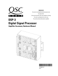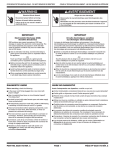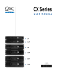
1
Film-Tech
The information contained in this Adobe Acrobat pdf
file is provided at your own risk and good judgment.
These manuals are designed to facilitate the
exchange of information related to cinema
projection and film handling, with no warranties nor
obligations from the authors, for qualified field
service engineers.
If you are not a qualified technician, please make no
adjuatments to anything you may read about in these
Adobe manual downloads
www.film-tech.com
CM16
MultiSignal
Processor
HARDWARE
MANUAL
Rev. B
2 0 M I P S D I G I TA L C O N T R O L M O N I TO R I N G P R O C E S S O R
C M 16
M U LT I S I G N A L P R O C E S S O R
▼
CM16
123456789012345678901234567890
123456789012345678901234567890
123456789012345678901234567890
123456789012345678901234567890
123456789012345678901234567890
123456789012345678901234567890
123456789012345678901234567890
123456789012345678901234567890
123456789012345678901234567890
123456789012345678901234567890
123456789012345678901234567890
19
Table of Contents
CM16 MultiSignal Processor User Manual
I.
INTRODUCTION .......................................................................................................................................... 3
Physical characteristics ................................................................................................................................. 3
Functional description ................................................................................................................................... 5
Network description ...................................................................................................................................... 6
II.
INSTALLATION .......................................................................................................................................... 10
Location considerations ............................................................................................................................... 10
Mounting the CM16 MultiSignal Processor ............................................................................................... 10
Connecting to AC power ............................................................................................................................. 11
Connecting to amplifiers ............................................................................................................................. 11
Connecting audio and logic cabling ............................................................................................................ 11
Program inputs ............................................................................................................................................. 11
Page .............................................................................................................................................................. 11
Monitor chain ............................................................................................................................................... 12
Contact closures .......................................................................................................................................... 12
Isolated contact outputs .............................................................................................................................. 12
III. SPECIFICATIONS ....................................................................................................................................... 13
IV. ARCHITECT’S AND ENGINEER’S SPECIFICATIONS ........................................................................... 16
V.
APPENDIX: Ethernet cabling; Data port pinout ................................................................................ 17
VI. QSC ADDRESS AND TELEPHONE INFORMATION .............................................................................. 18
1
EXPLANATION OF GRAPHICAL
SYMBOLS
The lightning flash with arrowhead symbol, within an equilateral triangle, is
intended to alert the user to the presence of uninsulated “dangerous voltage” within the product’s enclosure
that may be of sufficient magnitude to
constitute a risk of electric shock to
humans.
CAUTION
RISK OF ELECTRIC SHOCK
DO NOT OPEN
CAUTION: To reduce the risk of electric shock, do not
remove the cover. No user-serviceable parts inside.
Refer servicing to qualified service personnel.
WARNING: To prevent fire or electric shock, do not
expose this equipment to rain or moisture.
The exclamation point within an equilateral triangle is intended to alert
the users to the presence of important operating and maintenance (servicing) instructions in the literature
accompanying the product.
EXPLICATION DES SYMBOLES
GRAPHIQUES
Le symbole éclair avec point de flèche
à l’intrérieur d’un triangle équilatéral
est utilisé pour alerter l’utilisateur de la
presence à l’intérieur du coffret de
“voltage dangereux” non isolé
d’ampleur suffisante pour constituer
un risque d’elétrocution.
Le point d’exclamation à l’intérieur
d’un triangle équilatéral est employé
pour alerter les utilisateurs de la
présence d’instructions importantes
pour le fonctionnement et l’entretien
(service) dans le livret d’instruction
accompagnant l’appareil.
ERKLÄRUNG DER GRAPHISCHEN
SYMBOLE
Der Blitz nach unten zeigendem Pfeil in
einem gleichseitigen Dreieck weist den
Benutzer auf das Vorhandensein einer
unisolierten, gefährlichen Spannung“
”
im Gehäuse hin, die stark sein kann,
einer Person einen elektrischen Schlag
zu versetzen.
Das
Ausrufzeichen
in
einem
gleichseitigen Dreieck weist den
Benutzer auf wichtige Betriebs- und
Wartungs- vorschriften in den
beiliegenden Unterlagen des Gerätes
hin.
DECLARATION OF CONFORMITY
for all CX and CXT models
We declare as our sole responsibility that this
product is in compliance with the EMC Directive 89/336/EEC and conforms to the requirements of the Harmonized Product Standards
EN 55013 (Product Emissions), and EN 55020
(Product Immunity).
2
AVIS
RISQUE DE CHOC ÉLECTRIQUE
NE PAS OUVRIR
ATTENTION: Pour eviter les risques de choc électrique,
ne pas enlever le courvercle. Aucun entretien de
pièces intérieures par l’usager. Confier l’entretien au
personnel qualifié.
AVIS: Pour eviter les risques d’incendie ou
d’électrocution, n’exposez pas cet article à la pluie ou
a l’humidité.
VORSICHT
GEFAHR EINES ELEKTRISCHEN
SCHLAGES. NICHT ÖFFNEN!
VORSICHT: Um das Risiko eines elektrischen Schlages
zu vermindern, Abdeckung nicht entfernen! Keine
Benutzer Wartungsteile im Innern. Wartung nur durch
qualifiertes Wartungspersonal.
WARNUNG: Zur vermeidung von Feuer oder
elektrischen Schlägen, das Gerät nicht mit Regen
oder Feuchtigkeit in Berührung bringen!
SAFEGUARDS
Electrical energy can perform many useful functions. This unit has been engineered and manufactured to assure your personal safety. Improper use
can result in potential electrical shock or fire hazards.
In order not to defeat the safeguards, observe the
following instructions for its installation, use and
servicing.
PRECAUTIONS
L’énergie électrique peut remplir de nombreuses
fonctions utiles. Cet appariel a été conçu et réalisé
pour assurer une sécurité personnelle entiére. Une
utilisation impropre peut entraîner des risques
d’électrocution ou d’incendie. Dans le but de ne pas
rendre inutiles les mesures de sécurité, bien observer les instructions suivantes pour l’installation,
l’utilisation et l’entretien de l’appareil.
FEDERAL
COMMUNICATIONS
COMMISSION (FCC)
INFORMATION
NOTE: This equipment has been
tested and found to comply
with the limits for a Class A
digital device, pursuant to Part
15 of the FCC Rules. These
limits are designed to provide
reasonable protection against
harmful interference in a commercial installation. This
equipment generates, uses,
and can radiate radio frequency
energy and, if not installed and
used in accordance with the
instructions, may cause harmful interference to radio communications. Operation of this
equipment in a residential area
is likely to cause harmful interference, in which case the
user will be required to correct
the interference at his or her
own expense.
I. INTRODUCTION
The QSC CM16 MultiSignal Processor offers powerful amplifier management in a QSControl2 networked audio
system, using Ethernet networking technology to communicate with the host computer/system controller.
The system controller computer itself uses application software to operate the networked audio system, including
the CM16s and their amplifiers. The software operates on the Windows 95 operating system and can be
customized using Microsoft Visual Basic Professional Edition®. See the software manual or help file for more
information on software usage and functions.
The CM16 MultiSignal Processor performs control and monitoring functions for up to eight dual-channel
amplifiers, each equipped with a Data Port—either built-in or on a DP1 Data Port Module. QSC PowerLight Series
amplifiers (except for early models not equipped with data ports) have built-in Data Ports for this purpose, while
CX, EX, and MXa Series amplifiers require a DP1 accessory (available from QSC or an authorized QSC dealer)
installed in the Open Input Architecture slot. PowerLight amplifiers have full control and monitoring functionality,
while the number of control and monitoring functions available through the DP1 depends on the amplifier series
used. MXa and CX Series amplifiers have somewhat fewer available control and monitoring functions than the
EX Series; for more information consult the documentation included with the DP1.
The Data Port uses an HD15 connector, which is the same type that standard VGA computer monitors and video
cards use. This allows you to use a standard VGA cable for interconnecting an amplifier and a CM16 unit.
A CM16 unit controls and monitors as many as eight amplifiers; they are designated in this manual and on the
rear panel of the unit as Amp A through Amp H. A network may have multiple CM16’s, providing remote
management for systems ranging from a few up to hundreds of amplifiers.
PHYSICAL CHARACTERISTICS
Each CM16 unit is two rack spaces in height and has an internal AC power supply. Its chassis depth is 41.9 cm,
or 16.5 inches, plus 1-inch (2.54 cm) rear support tabs.
The rear panel has a female RJ-45 jack for connecting to an Ethernet using 10BASE-T wiring. An AUI interface
allows you to use an appropriate transceiver for 10BASE-F (fiber optic), 10BASE-5 (thick coaxial cable, also called
ThickNet), 10BASE-2 (thin coaxial cable, such as RG-58 or equivalent, also known as Thin Ethernet, ThinNet, or
CheaperNet), or other Ethernet media. The raw data rate is 10 Mbps.
3
Figure 1 shows the front panel of a CM16 unit, including the AC power switch and several LED indicators:
2 0 M I P S D I G I TA L C O N T R O L M O N I TO R I N G P R O C E S S O R
Figure 1
CM16 MultiSignal
Processor front
panel
C M 16
M U LT I S I G N A L P R O C E S S O R
Figure 2 shows the rear panel of a CM16 unit and its features:
1
Figure 2
CM16 MultiSignal
Processor rear
panel
PROGRAM INPUTS
AMP A
AMP B
2
3
4
G
G
AMP A
1
2
5
PROGRAM INPUTS
AMP C
AMP D
6
7
8
6
6
6
11
PROGRAM INPUTS
AMP G
AMP H
13
14
15
16
G
G
AMP D
7 DSP 8
5
1
6
10
15
6
11
CONTACT
CLOSURES
IN1
G
IN2
IN3
AMP H
16
15
5
6
11
LINK STATUS
XMT
RCV
AUI
10BASE T
1
6
10
15
11
One RJ-45 jack for connecting to a 10BASE-T Ethernet computer network
One AUI connector for connecting a transceiver to use with other Ethernet media
One IEC connector for a detachable AC power cord (included)
Four contact closure inputs for remote sensing
Four SPDT relay contact outputs for remote switching
Three LED indicators to show network communication status
“Euro-style” detachable terminal strips for line-level audio inputs, monitor chain input and output, contact closure
logic inputs, and relay contact outputs
AC power
Each CM16 device is factory-configured to operate on 100, 120, or 230 volts, 50 or 60 Hz; a label on the bottom
of the unit shows the correct operating voltage. Make sure you connect the CM16 unit only to the correct voltage;
otherwise, you might damage it and also create a dangerous situation for yourself and others. The detachable
power cord attaches to the CM16 unit via the IEC connector on the rear panel. A front panel LED, located above
4
RISK OF SHOCK
DO NOT OPEN
6
Eight HD-15 connectors for connecting to data ports of amplifiers A through H
the power switch, indicates when the CM16 is powered up.
CAUTION
WARNING: TO REDUCE THE RISK OF ELECTRIC SHOCK DO NOT REMOVE COVER.
NO USER SERVICEABLE PARTS INSIDE. DO NOT EXPOSE THIS EQUIPMENT TO
RAIN OR MOISTURE. REFER SERVICING TO QUALIFIED SERVICE PERSONNEL.
AVERTISSEMENT:RISQUE DE CHOC ELECTRIQUE-NE PAS OUVRIR.
ISOLATED CONTACT OUTPUTS
QSC AUDIO
IN4
RLY1
RLY2
RLY3
RLY4
PRODUCTS INC.
NC NO C NC NO C NC NO C NC NO C
MADE IN U.S.A.
1
10
15
1
10
15
AVIS
RISQUE DE CHOC
ELECTRIQUE NE
PAS OUVRIR
PAGE
G
11
AMP G
13
14
5
1
10
15
G
11
AMP F
11
12
5
1
PROGRAM INPUTS
AMP E
AMP F
10
11
12
AMP C
5 DSP 6
5
1
11
AMP E
10
9
10
15
9
G
10
15
11
5
G
AMP B
3
4
5
1
10
15
5
ETHERNET
MONITOR CHAIN
OUT
IN
G
Amp A (Ch 1 & 2)
PROGRAM
INPUTS
Input Source:
Normal / Page
Bridge
Mode
Detect
Meter
Gain Control
Mute
Polarity
Mon 1
Input
Sensitivity:
+4 / -10 dBu
Power
Status
Detect
Meter
Input Source:
Normal / Page
Mon 2
Meter
Meter
Gain Control
Mute
Polarity
Mon 1
Amplifier
Model
Detect
Standby/
Operate
Gain
Adj for
each
tap
Mon 2
Detect
Protect
status
Meter
Operating
Temp
Detect
Clip
Detect
Protect
status
Meter
Operating
Temp
Detect
Clip
Mon 1
Mon 2
Mon 3
Off
Ch 1
Detect
Output
short
Detect
Output
Open
Meter
Output
Amps
Meter
Output
Volts
Detect
Output
short
Detect
Output
Open
Meter
Output
Amps
Meter
Output
Volts
Mon 3
Meter
Mon 3
Gain
Adj for
each
tap
Mon 1
Mon 2
Mon 3
Off
Ch 2
Meter
POWER AMPLIFIER
DATAPORT INTERFACE
Input
Sensitivity:
+4 / -10 dBu
Amps B through H (same as Amp A)
PAGING
INPUT
MONITOR
INPUT
(summing)
AUI
10BASE-T
MONITOR
OUTPUT
MONITOR MODULE
+
CONTACT CLOSURE INPUT/OUTPUT
TRIGGER
OUTPUTS
TRIGGER
INPUTS
INTERNAL
MICROCONTROLLER
Paging Input
Sensitivity:
+4 / -10
ETHERNET
PAGING INPUT
Functional block diagram of the CM16 MultiSignal Processor
FUNCTIONAL DESCRIPTION
The CM16 performs control and monitoring functions remotely between the amplifiers and the host computer.
EX
(w S e r i
ith
e
DP s
-1
ca
rd)
MX
a
(w
S
ith erie
DP s
-1
ca
rd)
CX
,
(w CXt
ith
S
DP eries
-1
*
ca
rd)
Po
we
rLi
gh
t S
eri
es
This matrix indicates which control functions are available for various models of QSC amplifiers.
Channel signal gain
•
•
•
•
Channel signal mute
•
•
•
•
Channel signal polarity
•
•
•
•
Channel input sensitivity select
(+4 dBu or -10 dBV)
•
•
•
•
Remote power on/standby
•
•†
•†
•†
Paging or normal input select
•
•
•
•
*Except CX4 and CX4T
†Units with RPC only
5
Note that the PowerLight models are the only ones with built-in remote turn-on/turn-off capability; certain other
models require the installation of an appropriate RPC remote power control card. Contact the QSC Technical
Services department for information on what amplifier models can receive this upgrade.
CM16 input gain metering
(pre-fader)
•
CM16 output/amp input gain
metering (post-fader)
EX
(w Seri
ith
e
DP s
-1
ca
rd)
MX
a
(w
S
ith erie
DP s
-1
ca
rd)
CX
,
(w CXt
ith
S
DP eries
-1
*
ca
rd)
Po
we
rLi
gh
t S
eri
es
This matrix indicates which monitoring functions are available for various QSC amplifier models.
•
•
•
•
•
•
•
Power status detect
•
•
•
•
Bridge mode detect
•
•
•
•
Amplifier model detect
•
•
•
•
Protect status detect
•
•
•†
•
Heat sink temperature metering
•
•
Clip detect
•
•
•†
•
Output short detect
•
Output open detect
•
Amplifier channel output metering
(voltage and current)
•
V only
V only
V only
Source-selectable signal monitor
•
•
•
•
*Except CX4 and CX4T
†Except MX3000a
There are also four discrete floating relay contact closure outputs for remotely switching external devices, up
to 250 mA (500 mA steady-state) per contact pair. Four discrete single-ended logic inputs allow for sensing
external events or switches; these inputs have internal sense voltage sources, so they are compatible with both
logic devices and switches.
NETWORK DESCRIPTION
QSC CM16 MultiSignal Processors are designed to operate on a standard IEEE 802.3 Ethernet, and each one
operates as a respective node on its network. Each unit contains a unique Ethernet hardware address in nonvolatile memory, and will therefore present no conflict with any other node on the same network. You can even
use CM16 devices on a network shared with other networked devices, such as servers, workstations, and other
computers, although these other devices may affect network performance if their rate of network utilization is
very high. Ethernet devices such as hubs, repeaters, and routers will usually afford you the flexibility
to configure the network as needed.
Any system controller computer on the network must have an Ethernet-compatible network interface
card (NIC) installed. To allow you to operate the network even during power interruptions, it might
be a good idea to use an uninterruptible power supply (UPS) with the host computer(s) and any hubs
or repeaters.
A female RJ-45 connector on the rear panel allows a direct connection to a 10BASE-T network. Use
Category 3 or better unshielded twisted pair (UTP) Ethernet cable. (Most ready-made Ethernet patch
6
Connecting to Ethernet
cables available today are rated at least Category 5, so they would be perfectly suitable for the application.) For
use with other Ethernet medium, such as 10BASE-2, 10BASE-5, 100BASE-T, 100BASE-F, etc., the rear panel also
has an attachment unit interface (AUI) connector, to which you would attach a suitable transceiver.
Selecting AUI or 10BASE-T network connections
10BASE T
ETHERNET
A pushbutton switch next to the RJ-45 connector allows you to switch the network connection between the 10BASE-T
Ethernet connection—provided by the RJ-45 connector—and a transceiver connected to the AUI
connector. If the switch is in the in position, the RJ-45 connection is active; if the switch is out, the AUI is.
AUI/10BASE-T pushbutton selector switch
IN = 10BASE-T
OUT = AUI
Network status and diagnostic LED indicators
For diagnostic purposes, there are LED indicators on both the front and rear panels of the CM16.
The ones on the rear are located next to the multi-pin AUI connector and are labeled LINK STATUS, XMT, and
RCV.
LINK STATUS
XMT
RCV
A
LINK STATUS—When lit, this LED indicates that the CM16 is connected to an operating Ethernet network. If
it is unlit, there is probably some problem in the network cabling between the CM16 and the hub, or
possibly a fault in the hub. This LED only indicates a link via the RJ-45 connector, not via an AUI (most
AUI transceivers have their own LED indicators for status, transmit, and receive).
XMT—This LED lights to indicate that the CM16 is transmitting data over the network.
RCV—This LED lights up whenever the CM16 receives data from over the network.
The status LEDs on the front panel are labeled DIAGNOSTIC, LINK STATUS, and NETWORK ACTIVITY. The
POWER LED is also on the front panel, although it really isn’t a network status indicator;
nevertheless, if it isn’t lit, the CM16 is either turned off or disconnected from the AC source,
so you wouldn’t see any network activity anyway.
DIAGNOSTIC—This LED performs several functions. When the CM16 is powered up, the LED
flashes to indicate that the unit is first performing a self-diagnostic test and then loading the current
settings the onboard flash memory. This takes several seconds, and if the LED stays on longer than
that, it indicates an internal hardware fault.
During operation, the CM16 continually performs a reduced set of self-diagnostic functions, including
a background memory check. If it detects a memory fault, the LED will flash at a rate of about 2 Hz;
if some other hardware fault is found, the LED will light continuously.
Also during operation, the operator can turn the LED on and off using a custom Visual Basic application
on the network’s system controller computer. This is useful for identifying individual CM16s on the
network.
LINK STATUS—This LED has the same function as the one on the rear panel, which is described above. This
LED only indicates a link via the RJ-45 connector, not via an AUI.
NETWORK ACTIVITY—This LED combines the functions of the rear-panel XMT and RCV LEDs, i.e., it lights
whenever the CM16 is transmitting or receiving data. If you want to think of it as a Boolean expression,
then NETWORK ACTIVITY = XMT or RCV.
7
Sample network topologies
AMP
The simplest network configuration
AMP
would be a single system controller com-
AMP
puter and a CM16, with a single network
AMP
cable connecting them. In this situation,
a normal Ethernet cable would not work;
instead, you would need an Ethernet
crossover cable, which is somewhat
analogous to a null-modem cable. The
Standard VGA cables
between CM16 and
amp data ports
CM16
C M 16
M U LT I S I G N A L P R O C E S S O R
AMP
RJ-45–RJ-45 Crossover cable
Category 3 or better
< 100 m (330 ft)
AMP
AMP
AMP
maximum cable length is 100 meters, or
330 feet.
For distances longer than 100 meters, you
AMP
need a repeater and standard category 3
AMP
or better UTP Ethernet cables. Instead of
a repeater, you can also use an active
hub—one which “cleans up” and retransmits the network traffic as a re-
AMP
AMP
AMP
peater does, only with multiple ports—
AMP
to allow for future expansion.
AMP
AMP
If there are two or more
CM16s in the network, or
there are other networked
devices present, use a hub to
create a star topology.
8
Standard VGA cables
between CM16 and
amp data ports
CM16
C M 16
M U LT I S I G N A L P R O C E S S O R
Repeater
or hub
RJ-45–RJ-45 Ethernet cable
Category 3 or better
< 100 m (330 ft)
AMP
Up to 8
amplifiers
Standard VGA cables
between CM16 and
amp data ports
CM16
C M 16
M U LT I S I G N A L P R O C E S S O R
Hub
RJ-45–RJ-45 Ethernet cable
Category 3 or better
< 100 m (330 ft)
AMP
To create the more complex
distributed star topologies necessary for larger systems, use
AMP
additional hubs. Some hubs
have special uplink ports for
Up to 8
amplifiers
CM16
connecting to other hubs via a
C M 16
M U LT I S I G N A L P R O C E S S O R
AMP
standard Ethernet cable; if the
hubs don’t have an uplink port,
AMP
CM16
Hub
C M 16
M U LT I S I G N A L P R O C E S S O R
Up to 8
amplifiers
use an Ethernet crossover cable
to link the hubs via their normal
ports.
AMP
AMP
Up to 8
amplifiers
AMP
AMP
CM16
C M 16
M U LT I S I G N A L P R O C E S S O R
CM16
C M 16
M U LT I S I G N A L P R O C E S S O R
Up to 8
amplifiers
AMP
9
II. INSTALLATION
LOCATION CONSIDERATIONS
The physical limitations of the Ethernet, the placement of the amplifiers, and the locations of the system operators
are the guiding points in determining where the CM16 devices and host computers should be installed. In turn,
their placement will determine the specific routing of the Ethernet cabling.
The system controller computer, naturally, should be located someplace convenient for the system operator.
Physically, each CM16 device must be located near the amplifiers to which it is connected. Typically, they would
be in the same or adjacent equipment racks. The connection between CM16 and amplifier is via a readily available
standard 15-conductor shielded VGA cable, which carries control and monitoring data to and from the amplifier,
and also carries two channels of audio signals to the amplifier. Standard, off-the-shelf VGA cables are typically
two to three meters long (about 6 to 10 feet).
The maximum length of any 10BASE-T Ethernet network segment—that is, the cabling between any node and
the next node, hub, or repeater—is 100 meters, or 328 feet, so you will need to place the hubs and/or repeaters
accordingly. If that is impractical because of very long distances, use appropriate AUI transceivers and
fiber optic cabling; this offers the possibility of segments up to 5 kilometers (approximately 16400
feet, or 3.1 miles) long for 10BASE-F networking. The AUI connector is located on the rear
panel, next to the RJ-45 jack. For larger networks, you might need
to use Ethernet routers.
MOUNTING THE CM16 MULTISIGNAL PROCESSOR
Use four screws to secure the front of the CM16 to the equipment
rack. For mobile, touring, or portable applications, provide a rear
support also; QSC’s Technical Services department stocks kits for
installing rear mounting ears.
The CM16 uses fan-drawn air for cooling. Its intake is on one side
panel of the chassis, and the exhaust slots are on the other side. Be
careful not to obstruct
these openings, and allow ample open space around them,
in order to maintain a free flow of air.
NOTE: The CM16’s recommended ambient operating
temperature is 0°–50° C (32°–122° F).
Do not install the unit in an environment that exposes it to temperatures outside thus range.
10
CONNECTING AC POWER
The CM16 uses a detachable power cord for connecting to a grounded AC source. Each unit is configured at the
factory to use a particular line voltage (100, 120, or 220–240 volts AC); that voltage is printed on the serial number
label affixed to the underside of the CM16 chassis. Make sure the power cord is suitable for the unit’s operating
voltage; connecting the CM16 to the wrong voltage is dangerous and may damage the unit.
A CM16 can be reconfigured to work with a different line voltage. Consult the QSC Technical Services department
for more information.
CONNECTING TO AMPLIFIERS
Use standard, off-the-shelf VGA cables to connect between the amplifiers’ data ports and their respective HD15 ports on the rear panel of the CM16 unit. The amplifier ports are labeled A through H on the CM16 rear panel.
All necessary data and audio signals to and from the amplifier pass through the VGA cable.
The CM16 automatically identifies the amplifier models attached to its ports. It provides this information over
the network to the QSControl2 software in the system controller computer, which can indicate on-screen the
models of amps A through H attached to each particular CM16 device. The CM16 and the software also use the
model identification information to set appropriate ranges for the amplifier output voltage and current metering.
CONNECTING AUDIO AND LOGIC CABLING
The terminal block portions of the barrier strip inputs and outputs detach for ease of service; it also allows you
to pre-wire the rack even before the CM16 is installed in the rack.
The diagram at left shows how to connect wire to a detachable
terminal strip.
The rear panel is labeled to designate the proper connections.
For audio inputs and outputs, the shields connect to the ground
terminal, labeled “G,” as shown here.
PROGRAM INPUTS
Connect signal inputs for the CM16 to the terminal strip labeled PROGRAM INPUTS, which has 16 balanced
signal inputs.
PAGE
This is a single-channel balanced input for a paging signal, which can be inserted into any of the amplifiers. Like
the CM16’s other functions, it selects the signal source following commands from the system controller computer.
11
MONITOR CHAIN
The CM16 provides three monitor points for each of the 16 individual amplifier signal paths: pre-fader, postfader, and amplifier output. These points are selectable via the QSControl2 software on the system controller
computer, and each has a separate gain adjustment, also controlled via the system controller computer.
A line-level balanced monitor signal appears at the OUT terminals of the MONITOR CHAIN terminal strip. You
can cascade multiple CM16 devices by connecting the monitor chain output of one to the monitor chain input
of the next. The monitor signal would typically feed an auxiliary return on a mixing board, or a single-channel
amplifier input, for remote monitoring purposes.
CONTACT CLOSURES
14
15
G
16
PAGE
G
Four switch-logic inputs on the CM16 allow remote sensing, signalling,
or whatever you wish to program them as in a custom Visual Basic
CONTACT
CLOSURES
IN1
IN2
IN3
PAS OUVRIR
DO NOT OPEN
WARNING: TO REDUCE THE RISK OF ELECTRIC SHOCK DO NOT REMOVE COVER.
NO USER SERVICEABLE PARTS INSIDE. DO NOT EXPOSE THIS EQUIPMENT TO
RAIN OR MOISTURE. REFER SERVICING TO QUALIFIED SERVICE PERSONNEL.
AVERTISSEMENT:RISQUE DE CHOC ELECTRIQUE-NE PAS OUVRIR.
ISOLATED CONTACT OUTPUTS
QSC AUDIO
IN4
RLY1
RLY2
RLY3
RLY4
PRODUCTS INC.
NC NO C NC NO C NC NO C NC NO C
MADE IN U.S.A.
application on the system controller computer.
ISOLATED CONTACT OUTPUTS
LINK STATUS
XMT
RCV
AUI
10BASE T
The CM16 has four relay outputs for actuating and controlling auxiliary devices via a custom Visual Basic
application on the system controller computer. Each output set has a normally-closed (NC), a normally-open (NO),
and a common terminal.
12
ETHERNET
III. SPECIFICATIONS
CM16 MultiSignal Processor
Input signal processing
Frequency response 20 Hz–20 kHz ±0.5 dB
Distortion
<0.002% THD @ +4 dBu out
Dynamic range
>112 dB unweighted
22 Hz–22 kHz
Data Port noise floor -90.5 dBu
Polarity
In-phase or inverted
Gain control range
0–86 dB in 0.5 dB steps
Precision attenuator better than 112 dB below
transients (“zipper” maximum output
noise)
Mute
Inputs
Program inputs
Paging inputs
Monitor bus input
Connector type
Type
Grounding
Nominal level
Maximum level
>86 dB attenuation
16
1
1
“Phoenix-style” (a.k.a.
“Euro-style”) detachable barrier
strips
Electronically balanced
All shield terminals connected to
chassis
+4 dBu/-10 dBV selectable
+21 dBu
Impedance
25 kW balanced
Common-mode rejection
>70 dB, 20 Hz–20 kHz
Crosstalk (inter<75 dB separation, 20 Hz–20 kHz
channel within
Data Port pair)
Crosstalk (intra<108 dB separation, 20 Hz–20 kHz
channel between
Data Port pairs)
Outputs
Program outputs
Connector type
Type
Monitor output
Connector
16 (via HD15)
8 HD15 data port connections
Special
1
“Phoenix-style” (a.k.a.
“Euro-style”) detachable barrier
strips
Type
Electronically balanced
Grounding
Shield terminal connected to
chassis
Nominal level +4 dBu
Maximum level +21 dBu
Output impedance
75W balanced
Output load
600W minimum
Power amplifier output processing
Power amplifier output monitoring
Output short detect*
Senses load <1W for Stereo/
Parallel modes; <2W in Bridged
Mono mode
Output open detect*
Senses load >60W
Output voltage meter
Range automatically matches to
amplifier model used
Output current meter
Range automatically matches to
amplifier model used
*Signal level must be higher than -32 dB, referenced to
maximum output of amplifier
13
Power amplifier management
Power amplifier interface
Compatibility
QSC PowerLight models and other
DP-1 compatible amplifiers
Connector and cable
HD15 VGA cable, 2 meters length
qualified, maximum length TBD
Channels
16 discrete channels (up to 8
dual-channel amplifiers)
Amplifier status monitor
Clip indicator
Senses channel clipping
Protect indicator
Temperature meter
Senses amplifier protect status
Reports amplifier operating
temperature
AC power control
AC mode control
Switches amplifier between
normal and standby mode
(PowerLight models and DP-1compatible models equipped with
RPC [Remote Power Control] only)
AC power indicator Indicates operate, standby, or
power-down mode
Control room foldback monitoring
Signal monitoring buses
(per CM16)
1
Internal signal tap points
Pre-fader input signal
16
Post-fader input signal
16
Power amplifier output
16
Monitor input
Mixed with tap point signal at
unity gain
Nominal level
+4 dBu
Maximum level
+21 dBu
Input impedance
25 kW balanced
Configuration
Active balanced, shield connected
to chassis
Common-mode rejection
>75 dB 20 Hz–20 kHz
Output
Sum of Monitor input and
signal from internal monitor
tap point
Frequency response 20 Hz–20 kHz ±0.5 dB
Distortion
<0.05% THD @ +4 dBu out
Noise floor
-90.5 dB
Nominal level
+4 dBu
Maximum level
+21 dBu
Output impedance 75W balanced
Output load
600W minimum
Configuration
Active balanced
Gain
Adjusts amplitude of signal from
tap point
Monitor in to monitor out
0 dB, ±1 dB
Control range
0 to -86 dB in 0.5 dB steps
Contact closure inputs and outputs
Inputs
4 discrete inputs
Configuration
Single-ended input
Resistance for closure detect
<10 W max
Resistance for open detect
>1 kW min
Sense current
1.5 mA maximum
Ground limits (“-” input terminal)
Potential to case: 3V maximum
Resistance to case: 100W
14
Outputs
Configuration
4 discrete outputs
Electromechanical relay contacts,
floating
Maximum steady-state current
0.5 A
Maximum switched current
0.25 A
Ground isolation
70 volts maximum
Connector
“Phoenix-style” (a.k.a.
“Euro-style”) detachable barrier
strips
Network Interface
Physical network
Raw data rate
Frame format
Connectors
Ethernet types
Cable type
Max cable length
Grounding
Ethernet
Transport network
TCP/IP family
10 megabits per second
Internetwork protocol
D.I.X. (Ethernet)
IP
RJ-45 female
Transport protocol UDP
AUI
Application protocol QSC24
10BASE-T (via RJ-45)
Version
1
one Media Attachment Unit (MAU)
Revision
7
10BASE-T: twisted pair
MAU (including but not limited to):
10BASE-F: optical fiber
10BASE-2: 50W coax
10BASE-T: 100 m to hub
10BASE-F: 5 km
10BASE-2: 635 m total
Floating
General
Physical
Height
Width
Depth
3.5” (2 RU)
19” (standard rack mount)
16.75” (42.5 cm), plus 1” (2.5 cm)
rear supports
Weight
22 lbs (10 kg)
Mounting
Rear support recommended for
portable or mobile use
Operating temperature
0 to 50° Celsius
AC Power
Voltage
Current
Frequency
Disconnect
75–110 VAC (labeled for 100V)
95–135 VAC (labeled for 120V)
200–255 VAC (labeled for 230V)
1.1 A RMS (@ 100V)
1 A RMS (@ 120V)
0.5 A RMS (@ 230V)
50 or 60 Hz
Detachable power cord with IEC
connector
15
IV. ARCHITECT’S AND ENGINEER’S SPECIFICATIONS
The CM16 Power Amplifier Controller shall provide
monitor signals. A monitor gain control shall
input, output, and status control for Data Port equipped
be provided for each monitor tap point to
QSC power amplifiers in an Ethernet-TCP/IP based
adjust the individual levels of the channel
network audio system. Sixteen independent channels
monitor signals prior to their being mixed
shall be provided, grouped in pairs to support eight
with the monitor input signal.
dual-channel power amplifiers.
Contact Closure I/O—The CM16 shall provide four
Amplifier Input Control and Monitoring—For each
trigger contact-closure sense inputs which
of the sixteen power amplifier input signals,
shall also be TTL signal compatible, and four
the CM16 shall provide gain, mute and polarity
dry-contact floating SPDT relay outputs.
control, pre and post fade signal level metering
and audio monitoring, and selectable +4 dBu/
-10 dBV input sensitivity. The CM16 shall
provide a page input, separate from the normal
program inputs, whose signal may preempt the
program signal of any or all of the sixteen
program channels. This input shall have selectable +4 dBu/-10 dBV sensitivity.
Data Network—All CM16 functions shall be controlled and monitored via an Ethernet digital
control network using the TCP/IP transport
protocol and the QSC24 control and monitoring application protocol. Rear-panel connections shall be provided for 10BASE-T Ethernet,
and an Ethernet AUI (Attachment Unit Interface) connector shall also be provided to
Amplifier Output Monitoring—For each of the six-
interface with other Ethernet media. Other
teen power amplifier outputs, the CM16
than the AC power switch and a network
shall provide clipping detection, short and
media type selector switch, the CM16 shall
open circuit detection, voltage and current
have no manual controls.
metering, and audio monitoring of the voltage signal.
Amplifier Interface—The CM16’s interface to each
power amplifier Data Port shall be via an
Amplifier Management—For each of the eight dual-
HD15 connector. The amplifier interface shall
channel power amplifiers, the CM16 shall
use a standard personal computer Video
provide AC standby/operate mode control,
Graphics Adapter (VGA) CRT monitor cable.
AC power state indication, temperature
This interface shall transmit two amplifier
metering, and protect status detection.
input audio signals as well as all control and
Audio Monitoring Chain—For each of the sixteen
program channels, the CM16 shall provide
three monitor points as follows: (1) pre-fader
gain control, (2) post-fader gain control, or (3)
monitoring signals. Special signal conditioning and grounding techniques shall be used
in this interface to ensure negligible levels of
noise and crosstalk.
power amplifier output. A channel’s monitor General—All audio inputs and outputs shall be baloutput may be selected from one of these
anced with a nominal input level of +4 dBu
three signals, or it may be switched off. The
and maximum level of +21 dBu. Input connec-
signal at the CM16’s monitor output connec-
tors shall be of the “Phoenix” detachable
tor shall be the sum of the signal at its monitor
terminal strip type.
input connector and the sixteen channel
16
V. APPENDIX
ETHERNET CABLING
This diagram shows the pinout for standard unshielded twisted-pair (UTP) network cable. Both ends of the cable
are wired identically.
RJ-45 pinout for a standard
Ethernet patch cable (both ends
indentical)
A crossover cable has the RX and TX wire pairs switched around at one end. There are only two likely situations
that would require a crossover cable: to connect a single system controller computer directly to a single CM16
device; and to cascade hubs that don’t have uplink ports.
RJ-45 pinout for an Ethernet
crossover cable
DATA PORT PINOUT
5 4 3 2 1
10 9 8 7 6
15 14 13 12 11
1
Audio to Channel 1 (+)
2
Standby control
3
VMON Channel 1 plus encode 1
4
IMON Channel 1 plus encode 2
5
Clip/protect Channel 1
6
Hard ground
7
Audio to Channel 1 (ground)
DP-1
8
Audio to Channel 2 (ground)
encode 1
Temperature, Channel 1
9
unused
PowerLight
encode 1
Bridge mode & power detect
encode 2
Temperature, Channel 1
encode 3
Standby mode detect
encode 4
Temperature, Channel 2
encode 2
Amp ID voltage
10 Amp reference ground
encode 3
Temperature, Channel 2
11 Audio to channel 2 (+)
encode 4
Bridge mode & power detect
12 Amp IDR (model ID)
13 VMON Channel 2 plus encode 3
14 IMON Channel 2 plus encode 4
15 Clip/protect Channel 2
17
V. QSC ADDRESS & TELEPHONE INFORMATION
Address:
QSC Audio Products, Inc.
1675 MacArthur Boulevard
Costa Mesa, CA 92626-1468 USA
Telephone Numbers:
Main Number
(714) 754-6175
Sales Direct Line
(714) 957-7100
Sales & Marketing
(800) 854-4079
(toll-free in U.S.A. only)
Technical Services (714) 957-7150
(800) 772-2834
(toll-free in U.S.A. only)
Facsimile Numbers:
Sales & Marketing FAX
(714) 754-6174
Technical Services FAX
(714) 754-6173
World Wide Web:
http://www.qscaudio.com
BBS/World Group:
QSC OnLine Technical Support
1200-14400 bps; 8N1
(714) 668-7567
(800) 856-6003
CompuServe:
GO QSCAUDIO
ID: 76702,2635 or QSC_AUDIO
18
1675 MacArthur Boulevard
20
Costa Mesa, California 92626 USA
PH: (714) 754-6175 FAX: (714) 754-6174
“QSC” and the QSC logo are registered with the U.S. Patent and Trademark Office