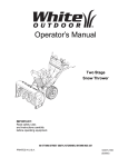
1
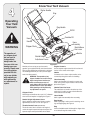
Safety • Assembly • Operation • Maintenance • Troubleshooting • Parts Lists • Warranty
OPERATOR’S MANUAL
Yard Vacuum/Chipper/Shredder with Vacuum/Hose
Model Series 060
IMPORTANT
READ SAFETY RULES AND INSTRUCTIONS CAREFULLY BEFORE OPERATION
Warning: This unit is equipped with an internal combustion engine and should not be used on or near any unimproved forest-covered, brushcovered or grass-covered land unless the engine’s exhaust system is equipped with a spark arrester meeting applicable local or state laws (if any).
If a spark arrester is used, it should be maintained in effective working order by the operator. In the State of California the above is required by law
(Section 4442 of the California Public Resources Code). Other states may have similar laws. Federal laws apply on federal lands. A spark arrester
for the muffler is available through your nearest engine authorized service dealer or contact the service department, P.O. Box 361131 Cleveland,
Ohio 44136-0019.
CUB CADET LLC, P.O. BOX 361131 CLEVELAND, OHIO 44136-0019
PRINTED IN U.S.A.
FORM NO. 769-02570
6/1/2006
This Operator’s Manual is an important part of your new yard vacuum. It will help you assemble, prepare
and maintain the unit for best performance. Please read and understand what it says.
Table of Contents
Customer Support............................................... 2
Safety Labels....................................................... 3
Safe Operation Practices.................................... 4
Setting Up Your Yard Vacuum............................. 6
Operating Your Yard Vacuum.............................. 8
Maintaining Your Yard Vacuum......................... 12
Troubleshooting................................................. 14
Parts List............................................................ 16
Warranty..............................................Back Cover
Finding and Recording Model Number
BEFORE ASSEMBLING YOUR NEW EQUIPMENT, please
locate the model plate on the equipment and copy the information to the sample model plate provided to the right. You
can locate the model plate by standing at the operating position and looking down at the rear of the deck. This information
will be necessary to use the manufacturer’s web site, to obtain
assistance from the Customer Support Department, or when
contacting an authorized service dealer.
Model Number
Serial Number
CUB CADET LLC
P. O. BOX 361131
www.cubcadet.com CLEVELAND, OH 44136
DEALER LOCATOR PHONE NUMBER: 877-282-8684
Customer Support
If you have difficulty assembling this product or have any questions regarding the controls, operation, or maintenance of this
unit, you can contact the dealer you purchased the unit from or choose from the options below:
3.The engine manufacturer is responsible for all enginerelated issues with regards to performance, power-rating,
specifications, warranty and service. Please refer to the
engine manufacturer’s Owner’s/Operator’s Manual, packed
separately with your unit, for more information.
1. Visit www.cubcadet.com for many useful suggestions.
Click on Customer Service or the Service Locator to find
the nearest Cub Cadet service dealer in your area.
2.To reach the Customer Dealer Referral Line, please call
1-877-282-8684.
1
Safety
Labels
$!.'%2
34/0
+EEP HANDS OUT OF INLETS WHILE
ENGINE IS RUNNING 2OTATING
BLADESAREINSIDE
&2/.47(%%,6!#55-./::,%(%)'(4
!$*534%2
()'(
,/7
&ORUSEIN
GRASSTOPICK
UPLEAVES
ANDDEBRIS
4OPICKUPWET
MATERIALPINE
CONESACORNS
ORMATERIALON
PAVEMENT
$!.'%2
4/!6/)$3%2)/53).*529
s 2%!$/0%2!4/2g3-!.5!,
s +%%0(!.$3/54/&).,%4!.$$)3#(!2'%/0%.).'37(),%-!#().%)3
25..).'2/4!4).'",!$%3!2%).3)$%
s 452. %.').% /&& !.$ !,,/7 )-0%,,%2 4/ #/-% 4/ #/-0,%4% 34/0
"%&/2%2%-/6).'"!'
s $/./4!44%-044/#,%!2!#,/'/2*!-7)4(4(%%.').%25..).'
s $/ ./4 /0%2!4% 5.)4 7)4(/54 "!' /2 /04)/.!, ",/7%2 #(54% ).
0,!#%
s $/./434!.$/27!,+).&2/.4/&",/7%2#(54%/2!)-)4!4"934!.$%23
/"*%#434(2/7./54/&$)3#(!2'%#!.#!53%0%23/.!,).*529
s $/./4/0%2!4%7(%.#(),$2%./2/4(%23!2%!2/5.$
s 7%!2!002/6%$3!&%49',!33%3
WARNING
This symbol points
out important safety
instructions which, if
not followed, could
endanger the personal
safety and/or property
of yourself and others.
Read and follow all
instructions in this
manual before attempting to operate
this machine. Failure
to comply with these
instructions may result
in personal injury. When
you see this symbol.
HEED ITS WARNING!
Your Responsibility
Restrict the use
of this power machine
to persons who read,
understand
and follow the warnings
and instructions
in this manual
and on the machine.
2
Safe
Operation
Practices
WARNING
This symbol points
out important safety
instructions which, if
not followed, could
endanger the personal
safety and/or property
of yourself and others.
Read and follow all
instructions in this
manual before attempting to operate
this machine. Failure
to comply with these
instructions may result
in personal injury. When
you see this symbol.
WARNING: Engine Exhaust, some of its constituents, and certain vehicle components contain or emit chemicals known to State of California to cause cancer and
birth defects or other reproductive harm.
DANGER: This machine was built to be operated according to the rules for safe operation in this
manual. As with any type of power equipment, carelessness or error on the part of the operator can
result in serious injury. This machine is capable of amputating hands and feet and throwing objects.
Failure to observe the following safety instructions could result in serious injury or death.
Training
Preparation
1. Read, understand, and follow all instructions on the machine and in the manual(s) before attempting to assemble
and operate. Keep this manual in a safe place for future
and regular reference and for ordering replacement parts.
2. Be familiar with all controls and their proper operation.
Know how to stop the machine and disengage them
quickly.
3. Never allow children under 16 years old to operate this
machine. Children 16 years old and over should read and
understand the operation instructions and safety rules in
this manual and should be trained and supervised by a
parent.
4. Never allow adults to operate this machine without proper
instruction.
5. Keep bystanders, helpers, pets, and children at least
75 feet from the machine while it is in operation. Stop
machine if anyone enters the area.
6. Never run an engine indoors or in a poorly ventilated area.
Engine exhaust contains carbon monoxide, an odorless
and deadly gas.
7. Do not put hands and feet near rotating parts or in the
feeding chambers and discharge opening. Contact with
the rotating impeller can amputate fingers, hands, and
feet.
8. Never attempt to unclog either the feed intake or discharge opening, remove or empty vacuum bag, or inspect
and repair the machine while the engine is running. Shut
the engine off and wait until all moving parts have come
to a complete stop. Disconnect the spark plug wire and
ground it against the engine.
1. Thoroughly inspect the area where the equipment is to
be used. Remove all rocks, bottles, cans, or other foreign
objects which could be picked up or thrown and cause
personal injury or damage to the machine.
2. Always wear safety glasses or safety goggles during operation or while performing an adjustment or repair, to protect
eyes. Thrown objects which ricochet can cause serious
injury to the eyes.
3. Wear sturdy, rough-soled work shoes and close-fitting
slacks and shirts. Loose fitting clothes or jewelry can be
caught in movable parts. Never operate this machine
in bare feet or sandals. Wear leather work gloves when
feeding material in the chipper chute.
4. Before starting, check all bolts and screws for proper tightness to be sure the machine is in safe working condition.
Also, visually inspect machine for any damage at frequent
intervals.
5. Maintain or replace safety and instructions labels, as
necessary.
6. To avoid personal injury or property damage use extreme
care in handling gasoline. Gasoline is extremely flammable
and the vapors are explosive. Serious personal injury can
occur when gasoline is spilled on yourself or your clothes
which can ignite. Wash your skin and change clothes
immediately.
a. Use only an approved gasoline container.
b. Extinguish all cigarettes, cigars, pipes, and other
sources of ignition.
c. Never fuel machine indoors.
d. Never remove gas cap or add fuel while the engine is hot
or running.
e. Allow engine to cool at least two minutes before refueling.
f. Never over fill fuel tank. Fill tank to no more than 1/2
inch below bottom of filler neck to provide space for fuel
expansion.
g. Replace gasoline cap and tighten securely.
h. If gasoline is spilled, wipe it off the engine and equipment. Move machine to another area. Wait 5 minutes
before starting the engine.
i. Never store the machine or fuel container inside where
there is an open flame, spark, or pilot light (e.g. furnace,
water heater, space heater, clothes dryer, etc.).
j. To reduce a fire hazard, keep machine free of grass,
leaves, or other debris build-up. Clean up oil or fuel
spillage and remove any fuel soaked debris.
k. Allow machine to cool at least 5 minutes before storing.
HEED ITS WARNING!
Your Responsibility
Restrict the use
of this power machine
to persons who read,
understand
and follow the warnings
and instructions
in this manual
and on the machine.
Operation
Maintenance & Storage
1. Do not put hands and feet near rotating parts or in the
feeding chambers and discharge opening. Contact with the
rotating impeller can amputate fingers, hands, and feet.
2. Before starting the machine, make sure the chipper chute,
feed intake, and cutting chamber are empty and free of all
debris.
3. Thoroughly inspect all material to be shredded and remove
any metal, rocks, bottles, cans, or other foreign objects
which could cause personal injury or damage to the
machine.
4. If the impeller strikes a foreign object or if your machine
should start making an unusual noise or vibration,
immediately shut the engine off. Allow the impeller to come
to a complete stop. Disconnect the spark plug wire, ground
it against the engine and perform the following steps:
a. Inspect for damage.
b. Repair or replace any damaged parts.
c. Check for any loose parts and tighten to assure
continued safe operation.
5. Do not allow an accumulation of processed material to build
up in the discharge area. This can prevent proper discharge
and result in kickback of material through the feed opening.
6. Do not attempt to shred or chip material larger than
specified on the machine or in this manual. Personal injury
or machine damage could result.
7. Never attempt to unclog either the feed intake or discharge
opening while the engine is running. Shut the engine off,
wait until all moving parts have stopped, disconnect the
spark plug wire and ground it against the engine before
clearing debris.
8. Never operate without vacuum bag and discharge chute
properly attached to the machine. Never empty or change
vacuum bag while the engine is running. Zippered end
of vacuum bag must be kept closed at all times during
operation.
9. Never operate without either the inlet nozzle or optional
hose attachment properly attached to the machine. Never
attempt to attach or change either attachment while the
engine is running.
10.Keep all guards, deflectors and safety devices in place and
operating properly.
11.Keep your face and body back and to the side of the chipper
chute while feeding material into the machine to avoid
accidental kickback injuries.
12.Never operate this machine without good visibility or light.
Always be sure of your footing and keep a firm hold on the
handles.
13.Do not operate this machine on a gravel surface.
14.Do not operate this machine while under the influence of
alcohol or drugs.
15.Muffler and engine become hot and can cause a burn. Do
not touch.
16.Never pick up or carry machine while the engine is running.
1. Never tamper with safety devices. Check their proper
operation regularly.
2. Check bolts and screws for proper tightness at frequent
intervals to keep the machine in safe working condition.
Also, visually inspect machine for any damage and repair,
if needed.
3. Before cleaning, repairing, or inspecting, stop the engine
and make certain the impeller and all moving parts have
stopped. Disconnect the spark plug wire and ground it
against the engine to prevent unintended starting.
4. Do not change the engine governor settings or overspeed
the engine. The governor controls the maximum safe
operating speed of the engine.
5. Maintain or replace safety and instruction labels, as
necessary.
6. Follow this manual for safe loading, unloading, transporting, and storage of this machine.
7. Never store the machine or fuel container inside where
there is an open flame, spark or pilot light such as a water
heater, furnace, clothes dryer, etc.
8. Always refer to the operator’s manual for proper instructions on off-season storage.
9. If the fuel tank has to be drained, do this outdoors.
10.Observe proper disposal laws and regulations for gas, oil,
etc. to protect the environment.
Do not modify engine
To avoid serious injury or death, do not modify engine in any
way. Tampering with the governor setting can lead to a runaway
engine and cause it to operate at unsafe speeds. Never tamper
with factory setting of engine governor.
Notice regarding Emissions
Engines which are certified to comply with California and
federal EPA emission regulations for SORE (Small Off Road
Equipment) are certified to operate on regular unleaded gasoline, and may include the following emission control systems:
Engine Modification (EM) and Three Way Catalyst (TWC) if so
equipped.
Your Responsibility
Restrict the use of this power machine to persons who read,
understand and follow the warnings and instructions in this
manual and on the machine.
2
Safe
Operation
Practices
WARNING
This symbol points
out important safety
instructions, which if
not followed, could
endanger the personal
safety and/or property
of yourself and others.
Read and follow all
instructions in this manual before attempting to
operate this machine.
Failure to comply with
these instructions may
result in personal injury.
When you see this
symbol.
HEED IT’S WARNING!
Your Responsibility
Restrict the use
of this power machine
to persons who read,
understand
and follow the warnings
and instructions
in this manual
and on the machine.
3
Wing Nut
Upper Hose
Handle Bracket
Cable Guide
Rope Guide
Setting Up
Your Yard
Vacuum
NOTE: This Operators Manual covers a range of product
specifications for various models. Characteristics and features discussed and/or illustrated in this manual may not
be applicable to all models. Cub Cadet reserves the right
to change product specifications, designs and equipment
without notice and without incurring obligation.
IMPORTANT: This unit is shipped without gasoline or oil
in the engine. Be certain to service engine with gasoline
and oil as instructed in the separate engine manual
before operating your machine.
Handle Knobs
Lower Hose
Handle Bracket
Carriage
Screws
Lower Handle
NOTE: Reference to right and left hand side of the Yard
Vacuum is observed from the operating position.
Wing Nuts
Opening Carton
1. Cut each corner of the carton vertically from top to
bottom.
Bag
2. Remove all loose parts.
IMPORTANT
This unit is shipped
without gasoline or
oil in the engine. Be
certain to service
engine with gasoline
and oil as instructed
in the separate engine
manual before operating your machine.
3. Remove loose packing material.
Safety Glasses
Removing Unit From Carton
Hose
Assembly
Bottle of Engine Oil
1. Lift unit from the rear to detach it from underlying
carton material and roll unit out of carton.
Blower Chute
2. Check carton thoroughly for any other loose parts.
(if equipped)
NOTE: Make sure not to crimp cables while removing
loose parts or the entire unit from the carton.
Operator’s Manual
Loose Parts In Carton (See Figure 3-1)
Figure 3-1
a. Upper and Lower Handle
b. Hose Assembly
NOTE:
Reference to right
and left hand side of
the Yard Vacuum is
observed from the
operating position.
c. Safety Glasses
d. Engine Oil (May be located in bag)
e. Bag
f. Blower Chute (If Equipped)
g. Operator’s Manual
3
Attaching The Handle
1. Remove the hairpin clips from the handle brackets and
remove the carriage screws and wing nuts from the
lower handle.
a. Place the bottom holes in lower handle over the
pins on the handle brackets and secure with
hairpin clips. See Figure 3-2.
b. Insert carriage screws through upper hole in lower
handle from the inside and secure with wing nuts.
See Figure 3-2.
Setting Up
Your Yard
Vacuum
B
2. a.Unfold the upper handle until it aligns with lower
handle. Make sure the rope guide is on the right
side of upper handle. See Figure 3-3.
A
IMPORTANT: Make sure the cables are routed outside
the lower handle. Also, do not crimp the cables while
lifting up the handles.
Figure 3-2
b.Secure the two handles by tightening the handle
knobs (carriage bolts must be seated properly into
the handle). See Figure 3-3.
3. Pull the two cable ties attached to the cables tight
approximately 8 inches from each cable end and place
the cables into the cable guide.
Rope Guide
4. Loosen the wing nut that secures the rope guide to the
right side of upper handle.
B
a. Pull the starter rope out of the engine slowly. See
Figure 3-4.
A
b. Slip the starter rope into the rope guide. Tighten
the wing nut. See Figure 3-4.
Figure 3-3
B
A
Figure 3-4
IMPORTANT
Make sure the cables
are routed outside the
lower handle. Also, do
not crimp the cables
while lifting up the
handles.
3
Attaching The Hose Assembly
5. a.Slide hose adapter of hose assembly into the
base adapter located on the left front of the Yard
Vacuum. See Figure 3-5.
b. Pull spring loaded pin out on the base and align pin
with the first hole (closest to the end of the tube) in
the hose adapter.
c. Release the pin to lock the hose in place.
6. a.Snap the hose handle first into the upper hose
handle bracket and then into the lower hose handle
bracket. See Figure 3-6.
b. Lay hose tubing on hanger bracket next to chipper
chute.
A
Setting Up
Your Yard
Vacuum
Align pin
with this
hole.
B
Attaching The Bag
7. Grasp bag handle with one hand and slide locking rod
on mounting bracket with other hand toward engine.
Use the end of mounting bracket as leverage when
sliding the locking rod.
Figure 3-5
NOTE: The bag/chute
switch button attached
to the mounting
bracket must be fully
depressed by the tip of
front tab on bag handle
when securing the bag
or engine will not start.
a. Slip bag over the rim of the discharge opening and
release locking rod to secure bag in place. See
Figure 3-7.
b. Snap bag clip to the top of the lower handle.
c. Place the lower straps on the bag over the top
of lower handle, hooking them on the studs. See
Figure 3-7.
A
NOTE: The bag/chute switch button attached to the
mounting bracket must be fully depressed by the tip of
front tab on bag handle when securing the bag or engine
will not start.
B
Figure 3-6
B
A
C
Figure 3-7
3
Attaching The Blower Chute
(If Equipped)
NOTE: The bag must be removed before installing the
blower chute.
8. a.Grasp blower chute with one hand and slide locking
rod on mounting bracket with other hand toward
engine. Use the end of mounting bracket as leverage when sliding the locking rod. See Figure 3-8.
b.Slip blower chute over rim of discharge opening
and release locking rod to secure chute in place.
c. Raise the nozzle height to the highest setting when
using the blower chute. Refer to nozzle height
adjustment in the MAINTENANCE section in this
manual.
B
A
Setting Up
Your Yard
Vacuum
NOTE: The bag/chute switch button attached to the
mounting bracket must be fully depressed by the tip of
front tab on the blower chute or engine will not start.
Figure 3-8
NOTE: The bag must
be removed before
installing the blower
chute.
Know Your Yard Vacuum
4
Starter Handle
Bag
Operating
Your Yard
Vacuum
Bag Handle
Oil Fill
Gasoline Fill
Hose
Handle
WARNING
The operation of
any chipper shredder can result in
foreign objects
being thrown into
the eyes, which can
damage your eyes
severely. Always wear
the safety glasses
provided with this
unit or eye shields
while operating or
while performing
any adjustments or
repairs.
Hose
Assembly
Chipper Chute
Nozzle/Hose
Vac Lever
Nozzle
Nozzle Height
Adjustment Lever
Figure 4-1
Engine Controls
Now that you have set up your yard vacuum for
operation, get acquainted with its controls and features. See the separate engine manual for the location and
These are described below and illustrated on this page. function of the controls on the engine.
This knowledge will allow you to use your new equipNozzle
ment to its fullest potential.
Yard waste such as leaves or pine needles can be
vacuumed up through the nozzle for shredding.
WARNING: The operation of any
chipper shredder can result in foreign
objects being thrown into the eyes,
which can damage your eyes severely. Always wear the safety glasses
provided with this unit or eye shields
while operating or while performing
any adjustments or repairs.
Hose Assembly
Used as an alternative to the nozzle to vacuum yard
waste such as leaves or pine needles in hard to reach
places. See Figure 9.
Chipper Chute
Allows twigs and small branches up to 1-1/2” in diameter
to be fed into the impeller for chipping. See Figure 9.
Nozzle Height Adjustment Lever
Used to adjust the nozzle ground clearance ranging
approximately from 5/8” to 4 1/8”. See Figure 9.
Throttle Control Lever (Not Shown)
The throttle control lever is located on the engine. It
controls the engine’s speed and stops the engine. See
separate engine manual packed with unit for details.
Nozzle/ Hose Vac Lever
The nozzle/hose vac handle is located on top of the
nozzle. Use it to switch vacuum suction between the
nozzle and the hose assembly.
Hose Handle
Used to guide hose assembly when vacuuming.
Bag Handle
Used to grasp bag in order to assist in attaching, removing, and emptying bag. See Figure 9.
Bag
Collects shredded material fed through the chipper chute
or vacuumed through the nozzle or hose.
10
Blower Chute
When attached to unit, the blower chute is used to blow
or scatter yard waste such as leaves, pine needle, or
small twigs across yard.
WARNING: The operation of the Yard Vacuum can
result in foreign objects being thrown into the eyes,
which can damage your eyes severely. Always
wear the safety glasses provided with this unit or
eye shields before chipping or blowing and while
performing any adjustments or repairs.
Gas And Oil Fill-Up
6. Pull rope with a rapid, continuous, full arm stroke.
Keep a firm grip on starter handle. Let rope rewind
slowly.
7. Repeat previous steps until engine fires. When
engine starts, move choke control (if equipped)
gradually to RUN position.
WARNING: Never run the engine indoors or in a
poorly ventilated area. Engine exhaust contains
carbon monoxide, an odorless and deadly gas.
Stopping Engine
Service the engine with gasoline and oil as instructed
in the separate engine manual packed with your Yard
Vacuum. Read instructions carefully.
1. Move throttle control lever to STOP or OFF position.
WARNING: Never fill fuel tank indoors with engine
running or until the engine has been allowed to cool
for at least two minutes after running.
To Empty Bag
Starting Engine
1. Attach spark plug wire to spark plug. Make certain the
metal cap on the end of the spark plug is
fastened securely over the metal tip on the
spark plug.
2. Make sure safety switch wire is connected to engine and properly grounded.
3.
4
Operating
Your Yard
Vacuum
2. Disconnect spark plug wire from spark plug and
ground against the engine.
1. a.Unhook bag straps from the lower handle.
b. Unsnap bag clip from the top of lower handle. See
Figure 4-2.
c. Grasp bag handle with one hand and pull lock
rod on mounting bracket with other hand toward
engine to release.
d.Lift bag off back of unit.
2. Twist the two buttons on the back of the bag to unlock and empty contents. See Figure 4-3. Hold bag
handle and bag clip while emptying the contents.
Engines with choke lever:
3. Compress bag opening and fold
inner flap over opening.
Move choke lever on engine to CHOKE
position. (A warm engine may not require
4. Fold outer flap over inner flap and
insert buttons on the bag through metal
outlets. See Figure 4-3.
choking).
Engines with primer:
Prime engine as instructed in separate engine manual. 5. Twist the buttons to lock bag. Place bag back onto
unit as instructed on page 8.
4. The throttle control is located on the engine. Move
engine throttle control lever to FAST or ON position.
5. Stand behind unit, grasp starter
handle and pull rope out slowly until engine
reaches start of compression cycle (rope
will pull slightly harder at this point).
11
WARNING
Never fill fuel tank
indoors with engine
running or until the
engine has been
allowed to cool for
at least two minutes
after running.
Never run the engine
indoors or in a poorly
ventilated area. Engine exhaust contains
carbon monoxide, an
odorless and deadly
gas.
To Remove Blower Chute
4
1. Grasp blower chute with one hand and pull lock rod
on mounting bracket with other hand toward engine to
release. Refer to Figure 8 on page 9.
B
2. Remove blower chute from rim of the discharge
opening.
Operating
Your Yard
Vacuum
D
C
Yard waste such as leaves and pine needles can be
vacuumed up for shredding. After material has been
shredded by the flail blades on the impeller assembly,
it will be discharged into catcher bag or through blower
chute. Do not attempt to shred or chip any material other
than vegetation found in a normal yard (i.e. branches,
leaves, twigs, etc.) Avoid fibrous plants such as tomato
vines until they are thoroughly dried out. Materials such
as stalks or heavy branches up to 1-1/2” in diameter may
be fed into the chipper chute.
A
WARNING: Do not attempt to shred,
chip, or vacuum any material larger
than specified on the machine or in this
manual. Personal injury or damage to
the machine could result.
Figure 4-2
IMPORTANT
Move the speed
control only when the
engine is running.
Changing the speed
control setting with the
engine off can damage
the yard vacuum.
IMPORTANT: The flail screen is located inside the
housing in the discharge area. If the flail screen becomes
clogged, remove and clean as instructed in the Maintenance section on page 16. For best performance, it is
also important to keep the chipper blade sharp.
WARNING: Do not at any time make
any adjustments without first stopping
engine and disconnecting spark plug
wire.
"UTTONS
)NNER
&LAP
/UTER&LAP
Figure 4-3
Figure 4-4
12
Using The Hose Assembly
4
1. Place nozzle/hose vac handle in the bottom position
on the nozzle to redirect vacuum to the hose assembly. See Figure 4-5.
2. The spring loaded pin must be in the second hole of
the hose adapter to operate the hose assembly.
3. Unhook the hose from upper handle bracket and
grasp the hose handle to guide while vacuuming yard
waste such as leaves or pine needles in hard to reach
places.
Operating
Your Yard
Vacuum
Figure 4-5
WARNING
Do not attempt
to shred, chip, or
vacuum any material
larger than specified
on the machine or in
this manual. Personal
injury or damage to
the machine could
result.
Do not at any time
make any adjustments without first
stopping engine and
disconnecting spark
plug wire.
13
5
4. Nozzle/Hose Vac Lever: Lubricate the nozzle/hose
vac lever on top of nozzle once a season with light oil.
Refer to Figure 4-1.
5. Engine: Follow the separate engine manual packed
with your unit for lubrication instructions.
Engine Care
Maintaining
Your Yard
Vacuum
Refer to the Maintenance section of the Briggs & Stratton
Owner/Operator manual packed with your unit. Read and
follow instructions carefully.
1. Check engine oil level before each use as instructed
in the separate engine manual.
2. Clean air cleaner’s precleaner every 25 hours under
normal conditions. Clean every few hours under
extremely dusty conditions. To service the air cleaner,
refer to the separate engine manual.
Figure 5-1
3. The spark plug should be cleaned and the gap reset
once a season. Refer to the separate engine manual
for correct plug type and gap specifications.
Removing The Flail Screen
WARNING
If the discharge area becomes clogged, remove the flail
screen and clean area as follows:
1. Stop the engine and make certain the Yard Vacuum
has come to a complete stop.
Always stop engine,
disconnect spark
plug, and ground
against engine before
cleaning, lubricating
or doing any kind of
maintenance on your
machine.
2. Disconnect and ground the spark plug wire to the
retaining post.
3. Remove the bag from the unit as instructed in the
OPERATING YOUR YARD VACUUM section to obtain
access to flail screen.
4. Remove self-tapping screw on right side of unit that
attaches to the fail screen. It may be necessary to
remove the hose bracket hanger to get access to the
hex screw. See Figure 5-1.
5. Remove hex screw on top of rear housing mounting
bracket and the flange lock nut that secures flail
screen. See Figure 5-1.
Figure 5-2
WARNING: Always stop engine,
disconnect spark plug, and ground
against engine before cleaning,
lubricating or doing any kind of
maintenance on your machine.
Lubrication
1. Wheels: Lubricate each wheel shoulder screw
(rear wheel) and pivot arm axle (front wheel) once a
season with light oil. See Figure 5-3.
2. Nozzle height adjustment levers: Lubricate the
pivot points of the nozzle height adjustment levers
once a season with light oil. Refer to Figure 7.
3. Locking Rod: Lubricate the locking rod with light oil
to ease the application of attaching on or removing
bag. Refer to Figure 6.
6. Remove and clean the screen by scraping or washing
with water. See Figure 5-2.
7. Reinstall the flail screen.
Sharpening Or Replacing Chipper
Blade
Because the engine on this unit has a tapered crankshaft,
a special impeller tool (part number 753-0900) is required
to remove the impeller assembly. For further assistance,
contact your local service dealer.
NOTE: When tipping the unit, empty the fuel tank and
keep spark plug side up.
1. Disconnect and ground the spark plug wire to retaining post.
2. Remove hose assembly and bag assembly.
14
3. Remove the front hubcaps, flange lock nuts, front
wheels, and wave washers that attach to the pivot arm
assemblies. See Figure 5-3.
5
Front Support Brace and Lock Nut
Pivot Arm Assembly
4. Remove the shoulder screws, thrust and bell washers
that go through the pivot arms to the front support
brace. The front support brace and lock nut can be
removed at this time as well. See Figure 5-3.
Bell Washer
Thrust Washer
Shoulder Screw
5. Remove the three screws on the upper housing that
secure the nozzle cover and the nine screws that
secure the lower housing to the upper housing. See
Figure 5-4.
Wave
Washer
6. Remove flange lock nut that secures flail screen to the
lower housing. The flail screen does not have to be
removed. Refer to Figure 5-1.
7. Remove the hex bolt, lock washer, and flat washer that
secure the impeller assembly to the crankshaft. See
Figure 5-5.
Lock Nut
Maintaining
Your Yard
Vacuum
Wheel
Figure 5-3
8. Apply lubricant to the threads of impeller removal
tool and then thread the tool into the crankshaft.
Stop when the impeller assembly can move on the
crankshaft.
WARNING
9. Remove the impeller assembly from the crankshaft.
Unthread the impeller removal tool from the impeller
assembly.
The chipper blade is
sharp. When sharpening blade, wear
leather work gloves
to protect your hands
and follow the original angle of grind.
10.Remove the blade using a 3/16” allen wrench on the
outside of the blade and 1/2” wrench on the impeller
assembly.
11.Replace or sharpen chipper blade. The blade can be
sharpened with a file or on a grinding wheel.
WARNING: The chipper blade is sharp.
When sharpening blade, wear leather
work gloves to protect your hands and
follow the original angle of grind.
Figure 5-4
12.Reassemble by performing the previous steps in the
opposite order and manner of removal.
IMPORTANT
Make certain chipper
blade is reassembled
with the sharp edge
facing upward. Tighten
blade screws to
between 210 in.-lbs.
and 250 in.-lbs. and
the impeller bolt to
between 375 in.-lbs.
and 425 in.-lbs.
IMPORTANT: Make certain chipper blade is reassembled with the sharp edge facing upward. Tighten
blade screws to between 210 in.-lbs. and 250 in.-lbs and
the impeller bolt to between 375 in.-lbs. and 425 in.-lbs.
Storing Your Yard Vacuum
1. Clean the equipment thoroughly.
2. Wipe equipment with an oiled rag to prevent rust.
3. Refer to engine manual for correct engine storage
instructions.
4. Store unit in a clean, dry area. Do not store next to
corrosive materials such as fertilizer.
Figure 5-5
15
6
Problem
Engine fails to start
Trouble
Shooting
Cause
1. Throttle lever not in correct starting
position.
1. Move throttle lever to FAST or
START position.
2. Spark plug wire disconnected.
2. Connect wire to spark plug.
3. Choke not in CHOKE position (if
equipped).
3. Move choke lever to CHOKE
position.
4. Fuel tank empty or stale fuel.
4. Fill tank with clean, fresh gasoline.
5. Engine not primed (if equipped).
5. Prime engine as instructed in
Engine Manual.
6. Faulty spark plug.
6. Clean, adjust gap, or replace.
7. Safety switch not depressed.
7. Safety switch must be depressed
by the front tab on the bag handle
when securing the bag.
8. Safety switch wire is not connected to
engine or not properly grounded.
Engine runs erratic
For repairs beyond
the minor adjustments
listed here, contact
an authorized service
dealer.
Engine overheats
Occasional skips
(hesitates) at
high speed
Excessive
Vibration
Unit does not
discharge
Rate of discharge
slows considerably
or composition of
discharged material
changes
Remedy
8. Connect safety switch wire to
engine connector and ground to
mounting bracket.
1. Spark plug wire loose.
1. Connect and tighten spark
plug wire.
2. Unit running on CHOKE (if equipped).
2. Move choke lever to OFF position.
3. Blocked fuel line or stale fuel.
3. Clean fuel line; fill tank with clean,
fresh gasoline.
4. Low engine RPM.
4. Always run engine at full throttle.
5. Water or dirt in fuel system.
5. Drain fuel tank. Refill with
fresh fuel.
6. Dirty air cleaner.
6. Refer to engine manual.
7. Carburetor out of adjustment.
7. See authorized service dealer.
1. Engine oil level low.
1. Fill crankcase with proper oil.
2. Dirty air cleaner.
2. Refer to engine manual.
3. Carburetor not adjusted properly.
3. See authorized service dealer.
1. Spark plug gap too close.
1. Adjust gap to .030”.
2. Carburetor idle mixture adjustment
improperly set.
2. See authorized service dealer.
1. Loose parts or damaged impeller.
1. See authorized service dealer.
1. Discharge area clogged.
1. Stop engine immediately and
disconnect spark plug wire. Clean
flail screen and inside of discharge
opening.
2. Foreign object lodged in impeller.
2. Stop engine and disconnect spark
plug wire. Remove lodged object.
3. Low engine RPM.
3. Always run engine at full throttle.
4. Vacuum bag is full.
4. Empty bag.
1. Low engine RPM.
1. Always run engine at full throttle.
2. Chipper blade dull.
2. Replace chipper blade or see your
authorized service dealer.
16
NOTES:
Use this page to make
notes and write down
important information.
To order replacement
parts, contact your
local Cub Cadet dealer;
or call our dealer
locator number at
1 (877) 282-8684;
or log onto
www.cubcadet.com
17
NOTES:
Use this page to make
notes and write down
important information.
To order replacement
parts, contact your
local Cub Cadet dealer;
or call our dealer
locator number at
1 (877) 282-8684;
or log onto
www.cubcadet.com
18
NOTES:
Use this page to make
notes and write down
important information.
To order replacement
parts, contact your
local Cub Cadet dealer;
or call our dealer
locator number at
1 (877) 282-8684;
or log onto
www.cubcadet.com
19
Model Series 060
2
6
3
34
8
9
5
11
34
23
10
7
22
A
12
17
36
50
14
4
13
7
15
27
25
26
33
A
40
21
37
39
44
42
52
46
41
28
16
38
24
20
18
43
40
1
50
45
29
48
51
47
30
50
49
31
32
20
35
19
7
Ref. Part No.
Description
Ref. Part No.
Description
1.
731-0982A
Radial Spoke Hubcap
28. 723-0295
Adjustment Clamp
2.
749-04172
Upper Handle
29. 749-1270
Nozzle Handle
3.
720-0279
Knob
30. 764-0648
Vacuum Hose
Handle Grip
4.
710-0599
Screw, 1/4-20 x.500
31.
5.
710-1205
Eye Bolt
32. 731-2292
Hose Adapter
6.
781-1056
Upper Handle Bracket
33. 712-0442
Cap Lock Nut, 1/4-20
7.
710-0726
Hex Cap Screw 5/16-12 x.750
34. 710-1611B
TT Screw, 5/16-18 x .750
8.
720-04072
Star Knob 5/16-18
35. 781-04082
Front Wheel Support Brace
9.
710-1174
Carriage Bolt
36. 781-04081
Rear Wheel Support Brace
10. 731-04911
Nozzle Handle Clip
37.
681-0156A
Handle Bracket Ass’y RH
11.
Lower Handle
681-0155A
Handle Brkt Ass’y LH (Not Shown)
749-04165
07071
12. 711-1293
Studs
38. 714-0104
Cotter Pin
13. 710-0703
Carriage Screw 1/4-20 x.75
39. 736-0105
Bell Washer.401 ID x.870 OD
14.
Wing Nut 1/4-20
40. 736-0232
Wave Washer.531 ID x.781 OD
15. 710-0751
Hex Cap Screw 1/4-20 x.620
41.
Shoulder Screw 3/8-16
16. 681-0195
Hose Base Adapter Assembly
42. 741-0751
Height Adjustment Bearing
(Incl. Ref.# 17-19)
43. 687-02094
Pivot Arm Assembly
E Ring.500 Dia
44. 720-0426
Height Adjustment Knob
18. 732-3035
Compression Spring
45. 732-1026
Spring Lever
19.
Clevis Pin
46. 687-02051
Height Lever Assembly
17.
712-0397
716-0104
711-1571
738-1015
(Incl. Ref.# 44-45)
20. 736-3020
Flat Washer.271 ID x.630 OD
21.
Upper Flail Housing
47.
22. 681-0122
Chipper Chute Assembly
48. 738-1172
Shoulder Screw,.750 x.500
23. 781-1058
Hose Hanger Bracket
49. 734-2004A
Wheel 8 x 2.125
24. 712-04064
Flange Lock Nut, 1/4-20
50. 712-0431
Flange Lock Nut, 3/8-16
25. 748-0457
Spacer
51.
Thrust Washer.375 ID x.70 OD
26. 731-2478
Hose Nozzle
52. 734-04007
27.
Hex Cap Screw 1/4-20 x 2.625
781-04071
710-3288
21
736-0741
736-0314
Bell Washer.760 ID x.25 OD
Wheel 9 x 2.125
Parts List
To order replacement
parts, contact your
local Cub Cadet dealer;
or call our dealer
locator number at
1 (877) 282-8684;
or log onto
www.cubcadet.com
Model Series 060
34
37
35
36
1
38
30
39
40
42
41
43
48
44
44
46
28
29
B
47
49
45
11
2
3
4
15
11
*
10
9
7
8
32
B
13
5
31
33
16
18
19
6
22
23
A
A
24
14
12
25
26
21
20
27
22
17
7
Ref. Part No.
Description
Ref. Part No.
Description
1.
664-0095
Bag Assembly
26.
732-1151A
Nozzle Door Torsion Spring
2.
681-0154
Screen Assembly
27.
731-2294A
Nozzle Door
3.
710-1054
Hex Screw 5/16-24 x 1.0
28.
764-0632A Bag
4.
781-0490
Chipper Blade
29.
664-04029
Chute Assembly
5.
781-0735
Pin Clip
30.
710-0726
Hex Index Screw, 5/16-12 x.750
6.
719-0329
Flail
31.
736-0247
Flat Washer.375 ID x 1.25 OD
7.
715-0166
Spiral Pin
32.
736-0217
Lock Washer 3/8
8.
711-1401
Clevis Pin
33.
710-0818
Hex Cap Screw 3/8-24 x 2.0
9.
712-0411
Lock Nut, 5/16-24
34.
725-1700
Switch Cover
10.
736-0119
Lock Washer, 5/16
35.
725-3166
Safety Switch
11.
681-0152
Impeller Assembly
36.
731-1613
Safety Switch Cover
(Incl. Ref.# 3 – 10)
37.
710-0224
Hex Washer Screw #10-16 x.50
12.
710-1650
Shoulder Screw, #12-24 x.30 x.46
38.
629-0920A Wire Harness
13.
781-0721B
Lower Flail Housing
39.
714-0104
Cotter Pin
14.
712-04063
Flange Lock Nut 5/16-18
40.
732-0962
Compression Spring
15.
710-0607
Screw, 5/16-18 x.500
41.
781-0778A
Mounting Bracket
16.
747-04297
Hinge Pin
42.
747-1153
Lock Rod
17.
731-2293A
Nozzle
43.
710-3195
Hex Cap Screw 5/16-18 x 4.5
18.
781-1064
Base Adapter Door
44.
710-3025
Hex Cap Screw 5/16-18 x.625
19.
732-1156
Torsion Spring
45.
710-0502A
Hex Washer Screw 3/8-16 x 1.25
20.
726-0106
Cap Speed Nut 1/4
46.
710-1220
Screw, #12-16 x.750
21.
711-1551
Pivot Rod
47.
710-0351
Screw #10 - 16 x.500
22.
731-04967
Nozzle Door Lever
48.
736-0607
External L-Washer 5/16
23.
710-1256
Hex Screw, #8-18 x 1.25
49.
726-0139
Speed Nut
24.
750-1294
Shoulder Spacer
—
723-0400
Safety Glasses (Not Shown)
25.
732-3118
Extension Spring
23
Parts List
To order replacement
parts, contact your
local Cub Cadet dealer;
or call our dealer
locator number at
1 (877) 282-8684;
or log onto
www.cubcadet.com
MANUFACTURER’S LIMITED WARRANTY FOR
The limited warranty set forth below is given by Cub Cadet LLC with
respect to new merchandise purchased and used in the United States, its
possessions and territories.
“Cub Cadet” warrants this product against defects in material and
workmanship for a period of two (2) years commencing on the date of
original purchase and will, at its option, repair or replace, free of charge,
any part found to be defective in materials or workmanship. This limited
warranty shall only apply if this product has been operated and maintained
in accordance with the Operator’s Manual furnished with the product, and
has not been subject to misuse, abuse, commercial use, neglect, accident,
improper maintenance, alteration, vandalism, theft, fire, water, or damage
because of other peril or natural disaster. Damage resulting from the
installation or use of any part, accessory or attachment not approved by
Cub Cadet for use with the product(s) covered by this manual will void
your warranty as to any resulting damage.
Normal wear parts are warranted to be free from defects in material and
workmanship for a period of thirty (30) days from the date of purchase.
Normal wear parts include, but are not limited to items such as: batteries,
belts, blades, blade adapters, grass bags, rider deck wheels, seats, snow
thrower skid shoes, shave plates, auger spiral rubber and tires.
HOW TO OBTAIN SERVICE: Warranty service is available, WITH
PROOF OF PURCHASE, through your local authorized service dealer.
To locate the dealer in your area, check your Yellow Pages, or contact
Cub Cadet LLC at P.O. Box 361131, Cleveland, Ohio 44136-0019, or call
1-877-282-8684, or log on to our Web site at www.cubcadet.com.
This limited warranty does not provide coverage in the following cases:
a. The engine or component parts thereof. These items may carry a separate manufacturer’s warranty. Refer to applicable
manufacturer’s warranty for terms and conditions.
b. Log splitter pumps, valves, and cylinders have a separate one year
warranty.
c. Routine maintenance items such as lubricants, filters, blade
sharpening, tune-ups, brake adjustments, clutch adjustments, deck
adjustments, and normal deterioration of the exterior finish due to use
or exposure.
e. Replacement parts that are not genuine Cub Cadet parts.
f. Service completed by someone other than an authorized service
dealer.
g. Transportation charges and service calls.
No implied warranty, including any implied warranty of merchantability of fitness for a particular purpose, applies after the applicable
period of express written warranty above as to the parts as identified. No other express warranty, whether written or oral, except as
mentioned above, given by any person or entity, including a dealer
or retailer, with respect to any product, shall bind Cub Cadet. During
the period of the warranty, the exclusive remedy is repair or replacement of the product as set forth above.
The provisions as set forth in this warranty provide the sole and
exclusive remedy arising from the sale. Cub Cadet shall not be liable
for incidental or consequential loss or damage including, without
limitation, expenses incurred for substitute or replacement lawn care
services or for rental expenses to temporarily replace a warranted
product.
Some states do not allow the exclusion or limitation of incidental or
consequential damages, or limitations on how long an implied warranty
lasts, so the above exclusions or limitations may not apply to you.
In no event shall recovery of any kind be greater than the amount of the
purchase price of the product sold. Alteration of safety features of the
product shall void this warranty. You assume the risk and liability for
loss, damage, or injury to you and your property and/or to others and their
property arising out of the misuse or inability to use the product.
This limited warranty shall not extend to anyone other than the original
purchaser or to the person for whom it was purchased as a gift.
HOW STATE LAW RELATES TO THIS WARRANTY: This limited warranty gives you specific legal rights, and you may also have other rights
which vary from state to state.
IMPORTANT: Owner must present Original Proof of Purchase to obtain
warranty coverage.
d. Cub Cadet does not extend any warranty for products sold or exported
outside of the United States, its possessions and territories, except
those sold through Cub Cadet’s authorized channels of export distribution
Cub Cadet LLC, P.O. BOX 361131 CLEVELAND, OHIO 44136-0019; Phone: 1-877-282-8684