1
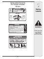
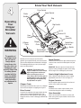
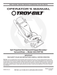
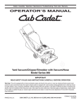
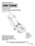
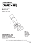
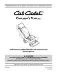
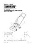
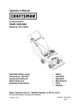
Safety • Assembly • Operation • Maintenance • Troubleshooting • Parts Lists • Warranty
OPERATOR’S MANUAL
Self Propelled Yard Vacuum/Chipper/Shredder/
Vacuum/Hose — Model Series 070
IMPORTANT
READ SAFETY RULES AND INSTRUCTIONS CAREFULLY BEFORE OPERATION
Warning: This unit is equipped with an internal combustion engine and should not be used on or near any unimproved forest-covered, brushcovered or grass-covered land unless the engine’s exhaust system is equipped with a spark arrester meeting applicable local or state laws (if any).
If a spark arrester is used, it should be maintained in effective working order by the operator. In the State of California the above is required by law
(Section 4442 of the California Public Resources Code). Other states may have similar laws. Federal laws apply on federal lands. A spark arrester
for the muffler is available through your nearest engine authorized service dealer or contact the service department, P.O. Box 361131 Cleveland,
Ohio 44136-0019.
PRINTED IN U.S.A.
TROY BILT LLC, P.O. BOX 361131 CLEVELAND, OHIO 44136-0019
FORM NO. 769-01295C
5/31/2007
This Operator’s Manual is an important part of your new chipper shredder vacuum. It will help you assemble, prepare and maintain the unit for best performance. Please read and understand what it says.
Table of Contents
Customer Support............................................... 2
Safety Labels....................................................... 3
Safe Operation Practices.................................... 4
Setting Up Your Chipper Shredder Vacuum...... 6
Operating Your Chipper Shredder Vacuum..... 10
Maintaining Your Chipper Shredder Vacuum.. 14
Troubleshooting................................................. 18
Parts List............................................................ 20
Warranty............................................... Back Page
Finding and Recording Model Number
BEFORE YOU START ASSEMBLING
YOUR NEW EQUIPMENT,
please locate the model plate on the equipment and copy
the information to the sample model plate provided to the
right. You can locate the model plate by standing behind the
unit and looking down at the frame below the engine. This
information will be necessary to use the manufacturer’s web
site and/or obtain assistance from the Customer Support
Department or an authorized service dealer.
www.troybilt.com
TROY-BILT LLC
P. O. BOX 3 6 1 1 3 1
CLEVELAND, OH 44136
330-558-7220
800-828-5500
Customer Support
Please do NOT return the unit to the retailer from which it was
purchased, without first contacting Customer Support.
If you have difficulty assembling this product or have any questions regarding the controls, operation, or maintenance of this
unit, you can seek help from the experts. Choose from the options below:
1. Visit troybilt.com. Click on the Support tab.
2.Phone a Customer Support Representative at 1 (800) 828-5500.
3.The engine manufacturer is responsible for all engine-related issues with regards to performance, power-rating, specifications, warranty and service. Please refer to the engine manufacturer’s Owner’s/Operator’s Manual, packed separately with
your unit, for more information.
Safety Labels Found On
Your Chipper Shredder
Vacuum
DANGER
STOP
Keep hands out of inlets while
engine is r unning.
Rotating
blades are inside.
FRONT WHEEL / VACUUM NOZZLE HEIGHT
ADJUSTER
HIGH
1
Safety
Labels
LOW
To pick up wet
material, pine
cones, acorns
or material on
pavement.
For use in
grass to pick
up leaves
and debris
DANGER
TO AVOID SERIOUS INJURY
• READ OPERATOR'S MANUAL.
• KEEP HANDS OUT OF INLET AND DISCHARGE OPENINGS WHILE MACHINE
IS RUNNING. ROTATING BLADES ARE INSIDE.
• TURN ENGINE OFF AND ALLOW IMPELLER TO COME TO COMPLETE STOP
BEFORE REMOVING BAG.
• DO NOT ATTEMPT TO CLEAR A CLOG OR JAMWITH THE ENGINE RUNNING.
• DO NOT OPERATE UNIT WITHOUT BAG OR OPTIONAL BLOWER CHUTE IN
PLACE.
• DO NOT STAND ORWALK IN FRONT OF BL
OWER CHUTE OR AIM IT
AT BYSTANDERS.
OBJECTS THROWN OUT OF DISCHARGE CAN CAUSE PERSONAL INJURY.
• DO NOT OPERATE WHEN CHILDREN OR OTHERS ARE AROUND.
• WEAR APPROVED SAFETY GLASSES.
DANGER
• KEEP HANDS OUT OF DISCHARGE OPENING.
• DO NOT STAND OR WALK IN FRONT OF
DISCHARGE OPENING OR AIM IT AT
BYSTANDERS. OBJECTS THROWN OUT OF
CHUTE CAN CAUSE PERSONAL INJURY
.
. S 30270
• KEEP CHILDREN AND OTHERS AWAY
WARNING
DO NOT remove safety
(or any) labels from
chipper shredder
vacuum for any reason.
2
Safe
Operation
Practices
WARNING
This symbol points
out important safety
instructions which, if
not followed, could
endanger the personal
safety and/or property
of yourself and others.
Read and follow all
instructions in this
manual before attempting to operate
this machine. Failure
to comply with these
instructions may result
in personal injury. When
you see this symbol.
WARNING: Engine Exhaust, some of its constituents, and certain vehicle components contain or emit chemicals known to State of California to cause cancer and
birth defects or other reproductive harm.
DANGER: This machine was built to be operated according to the rules for safe operation in this
manual. As with any type of power equipment, carelessness or error on the part of the operator can
result in serious injury. This machine is capable of amputating hands and feet and throwing objects.
Failure to observe the following safety instructions could result in serious injury or death.
Training
Preparation
1. Read, understand, and follow all instructions on the machine and in the manual(s) before attempting to assemble
and operate. Keep this manual in a safe place for future
and regular reference and for ordering replacement parts.
2. Be familiar with all controls and their proper operation.
Know how to stop the machine and disengage them
quickly.
3. Never allow children under 16 years old to operate this
machine. Children 16 years old and over should read and
understand the operation instructions and safety rules in
this manual and should be trained and supervised by a
parent.
4. Never allow adults to operate this machine without proper
instruction.
5. Keep bystanders, helpers, pets, and children at least
75 feet from the machine while it is in operation. Stop
machine if anyone enters the area.
6. Never run an engine indoors or in a poorly ventilated area.
Engine exhaust contains carbon monoxide, an odorless
and deadly gas.
7. Do not put hands and feet near rotating parts or in the
feeding chambers and discharge opening. Contact with
the rotating impeller can amputate fingers, hands, and
feet.
8. Never attempt to unclog either the feed intake or discharge opening, remove or empty vacuum bag, or inspect
and repair the machine while the engine is running. Shut
the engine off and wait until all moving parts have come
to a complete stop. Disconnect the spark plug wire and
ground it against the engine.
1. Thoroughly inspect the area where the equipment is to
be used. Remove all rocks, bottles, cans, or other foreign
objects which could be picked up or thrown and cause
personal injury or damage to the machine.
2. Always wear safety glasses or safety goggles during operation or while performing an adjustment or repair, to protect
eyes. Thrown objects which ricochet can cause serious
injury to the eyes.
3. Wear sturdy, rough-soled work shoes and close-fitting
slacks and shirts. Loose fitting clothes or jewelry can be
caught in movable parts. Never operate this machine
in bare feet or sandals. Wear leather work gloves when
feeding material in the chipper chute.
4. Before starting, check all bolts and screws for proper tightness to be sure the machine is in safe working condition.
Also, visually inspect machine for any damage at frequent
intervals.
5. Maintain or replace safety and instructions labels, as
necessary.
6. To avoid personal injury or property damage use extreme
care in handling gasoline. Gasoline is extremely flammable
and the vapors are explosive. Serious personal injury can
occur when gasoline is spilled on yourself or your clothes
which can ignite. Wash your skin and change clothes
immediately.
a. Use only an approved gasoline container.
b. Extinguish all cigarettes, cigars, pipes, and other
sources of ignition.
c. Never fuel machine indoors.
d. Never remove gas cap or add fuel while the engine is hot
or running.
e. Allow engine to cool at least two minutes before refueling.
f. Never over fill fuel tank. Fill tank to no more than 1/2
inch below bottom of filler neck to provide space for fuel
expansion.
g. Replace gasoline cap and tighten securely.
h. If gasoline is spilled, wipe it off the engine and equipment. Move machine to another area. Wait 5 minutes
before starting the engine.
i. Never store the machine or fuel container inside where
there is an open flame, spark, or pilot light (e.g. furnace,
water heater, space heater, clothes dryer, etc.).
j. To reduce a fire hazard, keep machine free of grass,
leaves, or other debris build-up. Clean up oil or fuel
spillage and remove any fuel soaked debris.
k. Allow machine to cool at least 5 minutes before storing.
HEED ITS WARNING!
Your Responsibility
Restrict the use
of this power machine
to persons who read,
understand
and follow the warnings
and instructions
in this manual
and on the machine.
Operation
Maintenance & Storage
1. Do not put hands and feet near rotating parts or in the
feeding chambers and discharge opening. Contact with the
rotating impeller can amputate fingers, hands, and feet.
2. Before starting the machine, make sure the chipper chute,
feed intake, and cutting chamber are empty and free of all
debris.
3. Thoroughly inspect all material to be shredded and remove
any metal, rocks, bottles, cans, or other foreign objects
which could cause personal injury or damage to the
machine.
4. If the impeller strikes a foreign object or if your machine
should start making an unusual noise or vibration,
immediately shut the engine off. Allow the impeller to come
to a complete stop. Disconnect the spark plug wire, ground
it against the engine and perform the following steps:
a. Inspect for damage.
b. Repair or replace any damaged parts.
c. Check for any loose parts and tighten to assure
continued safe operation.
5. Do not allow an accumulation of processed material to build
up in the discharge area. This can prevent proper discharge
and result in kickback of material through the feed opening.
6. Do not attempt to shred or chip material larger than
specified on the machine or in this manual. Personal injury
or machine damage could result.
7. Never attempt to unclog either the feed intake or discharge
opening while the engine is running. Shut the engine off,
wait until all moving parts have stopped, disconnect the
spark plug wire and ground it against the engine before
clearing debris.
8. Never operate without vacuum bag and discharge chute
properly attached to the machine. Never empty or change
vacuum bag while the engine is running. Zippered end
of vacuum bag must be kept closed at all times during
operation.
9. Never operate without either the inlet nozzle or optional
hose attachment properly attached to the machine. Never
attempt to attach or change either attachment while the
engine is running.
10.Keep all guards, deflectors and safety devices in place and
operating properly.
11.Keep your face and body back and to the side of the chipper
chute while feeding material into the machine to avoid
accidental kickback injuries.
12.Never operate this machine without good visibility or light.
Always be sure of your footing and keep a firm hold on the
handles.
13.Do not operate this machine on a gravel surface.
14.Do not operate this machine while under the influence of
alcohol or drugs.
15.Muffler and engine become hot and can cause a burn. Do
not touch.
16.Never pick up or carry machine while the engine is running.
1. Never tamper with safety devices. Check their proper
operation regularly.
2. Check bolts and screws for proper tightness at frequent
intervals to keep the machine in safe working condition.
Also, visually inspect machine for any damage and repair,
if needed.
3. Before cleaning, repairing, or inspecting, stop the engine
and make certain the impeller and all moving parts have
stopped. Disconnect the spark plug wire and ground it
against the engine to prevent unintended starting.
4. Do not change the engine governor settings or overspeed
the engine. The governor controls the maximum safe
operating speed of the engine.
5. Maintain or replace safety and instruction labels, as
necessary.
6. Follow this manual for safe loading, unloading, transporting, and storage of this machine.
7. Never store the machine or fuel container inside where
there is an open flame, spark or pilot light such as a water
heater, furnace, clothes dryer, etc.
8. Always refer to the operator’s manual for proper instructions on off-season storage.
9. If the fuel tank has to be drained, do this outdoors.
10.Observe proper disposal laws and regulations for gas, oil,
etc. to protect the environment.
Do not modify engine
To avoid serious injury or death, do not modify engine in any
way. Tampering with the governor setting can lead to a runaway
engine and cause it to operate at unsafe speeds. Never tamper
with factory setting of engine governor.
Notice regarding Emissions
Engines which are certified to comply with California and
federal EPA emission regulations for SORE (Small Off Road
Equipment) are certified to operate on regular unleaded gasoline, and may include the following emission control systems:
Engine Modification (EM) and Three Way Catalyst (TWC) if so
equipped.
Your Responsibility
Restrict the use of this power machine to persons who read,
understand and follow the warnings and instructions in this
manual and on the machine.
2
Safe
Operation
Practices
WARNING
This symbol points
out important safety
instructions, which if
not followed, could
endanger the personal
safety and/or property
of yourself and others.
Read and follow all
instructions in this manual before attempting to
operate this machine.
Failure to comply with
these instructions may
result in personal injury.
When you see this
symbol.
HEED IT’S WARNING!
Your Responsibility
Restrict the use
of this power machine
to persons who read,
understand
and follow the warnings
and instructions
in this manual
and on the machine.
3
Upper Handle
Drive Control
Speed Control
Wing Nut
Upper Hose
Handle Bracket
Cable Guide
Rope Guide
Setting Up
Your
Chipper
Shredder
Vacuum
Star Knob
Lower Hose
Handle Bracket
Carriage
Screw
Lower Handle
Wing Nut
Bag
IMPORTANT
This unit is shipped
without gasoline or
oil in the engine. Be
certain to service
engine with gasoline
and oil as instructed
in the separate engine
manual before operating your machine.
NOTE: Reference to
right and left hand
side of the Chipper/Shredder Vacuum
is observed from the
operating position.
Safety Glasses
Hose
Assembly
Bottle of Engine Oil
Blower Chute
Operator’s Manual
Figure 3-1
IMPORTANT: This unit is shipped without gasoline or oil
in the engine. Be certain to service engine with gasoline
and oil as instructed in the separate engine manual
before operating your machine.
Removing Unit From Carton
NOTE: Reference to right and left hand side of the Chipper/Shredder Vacuum is observed from the operating
position.
NOTE: Make sure not to crimp cables while removing
loose parts or the entire unit from the carton.
1. Lift unit from the rear to detach it from underlying
carton material and roll unit out of carton.
2. Check carton thoroughly for any other loose parts.
Loose Parts In Carton (See Figure 3-1)
Opening Carton
a. Upper and Lower Handle
1. Cut each corner of the carton vertically from top to
bottom.
b. Hose Assembly
c. Safety Glasses
2. Remove all loose parts.
d. Engine Oil (May be located in bag)
3. Remove loose packing material.
e. Bag
f. Blower Chute (If Equipped)
g. Operator’s Manual
3
Attaching The Handle
1. Remove the hairpin clips from the handle brackets and
remove the carriage screws and wing nuts from the
lower handle.
a. Place the bottom holes in lower handle over the
pins on the handle brackets and secure with
hairpin clips. See Figure 3-2.
b. Insert carriage screws through upper hole in lower
handle from the inside and secure with wing nuts.
See Figure 3-2.
Setting Up
Your
Chipper
Shredder
Vacuum
2. a.Unfold the upper handle until it aligns with lower
handle. Make sure the rope guide is on the right
side of upper handle. See Figure 3-3.
IMPORTANT: Make sure the cables are routed outside
the lower handle. Also, do not crimp the cables while
lifting up the handles.
Figure 3-2
b.Secure the two handles by tightening the star
knobs (carriage bolts must be seated properly into
the handle). See Figure 3-3.
3. Pull the two cable ties attached to the cables tight
approximately 8 inches from each cable end and place
the cables into the cable guide.
Rope Guide
4. Loosen the wing nut that secures the rope guide to the
right side of upper handle.
B
a. Pull the starter rope out of the engine slowly. See
Figure 3-4.
A
b. Slip the starter rope into the rope guide. Tighten
the wing nut. See Figure 3-4.
Figure 3-3
B
A
Figure 3-4
IMPORTANT
Make sure the cables
are routed outside the
lower handle. Also, do
not crimp the cables
while lifting up the
handles.
3
Attaching The Hose Assembly
5. a.Slide hose adapter of hose assembly into the
base adapter located on the left front of the Yard
Vacuum. See Figure 3-5.
b. Pull spring loaded pin out on the base and align pin
with the first hole (closest to the end of the tube) in
the hose adapter.
c. Release the pin to lock the hose in place.
6. a.Snap the hose handle first into the upper hose
handle bracket and then into the lower hose handle
bracket. See Figure 3-6.
b. Lay hose tubing on hanger bracket next to chipper
chute.
A
B
Setting Up
Your
Chipper
Shredder
Vacuum
Align pin
with this
hole.
Figure 3-5
NOTE: The bag/chute
switch button attached
to the mounting
bracket must be fully
depressed by the tip of
front tab on bag handle
when securing the bag
or engine will not start.
A
B
Figure 3-6
3
Attaching The Bag
7. Grasp bag handle with one hand and slide locking rod
on mounting bracket with other hand toward engine.
Use the end of mounting bracket as leverage when
sliding the locking rod.
A
a. Slip bag over the rim of the discharge opening and
release locking rod to secure bag in place. See
Figure 3-7.
B
b. Snap bag clip to the top of the lower handle.
c. Place the lower straps on the bag over the top
of lower handle, hooking them on the studs. See
Figure 3-7.
C
NOTE: The bag/chute switch button attached to the
mounting bracket must be fully depressed by the tip of
front tab on bag handle when securing the bag or engine
will not start.
Attaching The Blower Chute
Setting Up
Your
Chipper
Shredder
Vacuum
Figure 3-7
(If Equipped)
NOTE: The bag must be removed before installing the
blower chute.
8. a.Grasp blower chute with one hand and slide locking
rod on mounting bracket with other hand toward
engine. Use the end of mounting bracket as leverage when sliding the locking rod. See Figure 3-8.
b.Slip blower chute over rim of discharge opening
and release locking rod to secure chute in place.
c. Raise the nozzle height to the highest setting when
using the blower chute. Refer to nozzle height
adjustment in the Operating Your Chipper/
Shredder Vacuum section.
NOTE: The bag must
be removed before
installing the blower
chute.
NOTE: The bag/chute switch button attached to the
mounting bracket must be fully depressed by the tip of
front tab on the blower chute or engine will not start.
Figure 3-8
4
Know Your Yard Vacuum
Drive Control
Speed Control
Starter
Handle
Bag
Operating
Your
Chipper
Shredder
Vacuum
Bag Handle
Oil Fill
Gasoline Fill
Hose
Handle
† Blower
Chute
Hose
Assembly
Chipper
Chute
Nozzle/Hose
Vac Lever
Nozzle
Nozzle Height
Adjustment Lever
WARNING
The operation of
any chipper shredder can result in
foreign objects
being thrown into
the eyes, which can
damage your eyes
severely. Always wear
the safety glasses
provided with this
unit or eye shields
while operating or
while performing
any adjustments or
repairs.
† If Equipped
Figure 4-1
Speed Control
Now that you have set up your yard vacuum for
operation, get acquainted with its controls and features.
These are described below and illustrated on this page.
This knowledge will allow you to use your new equipment to its fullest potential.
Located on the left side of the upper handle, the speed
control is used to select the forward speed of the yard
vacuum.
IMPORTANT: Move the speed control only when the
engine is running. Changing the speed control setting
with the engine off can damage the yard vacuum.
WARNING: The operation of any
chipper shredder can result in foreign
objects being thrown into the eyes,
which can damage your eyes severely. Always wear the safety glasses
provided with this unit or eye shields
while operating or while performing
any adjustments or repairs.
Nozzle Height Adjustment Lever
Used to adjust the nozzle ground clearance ranging
approximately from 5/8” to 4 1/8”. See Figure 4-1.
Engine Controls
See the separate engine manual for the location and
function of the controls on the engine.
Chipper Chute
Allows twigs and small branches up to 1-1/2” in diameter
to be fed into the impeller for chipping. See Figure 4-1.
Drive Control
Located on the underside of the upper handle, the drive
control is used to engage/disengage wheels. Fully
squeeze the drive control against the upper handle to
engage the wheels; release to disengage. (DO NOT slip
clutch).
Nozzle
Yard waste such as leaves or pine needles can be
vacuumed up through the nozzle for shredding.
Hose Assembly
Used as an alternative to the nozzle to vacuum yard
waste such as leaves or pine needles in hard to reach
places. See Figure 4-1.
10
Nozzle/ Hose Vac Lever
The nozzle/hose vac handle is located on top of the
nozzle. Use it to switch vacuum suction between the
nozzle and the hose assembly.
Throttle Control
Hose Handle
Choke Control
Used to guide hose assembly when vacuuming.
Bag Handle
4
Operating
Your
Chipper
Shredder
Vacuum
Used to grasp bag in order to assist in attaching, removing, and emptying bag. See Figure 4-1.
Bag
Collects shredded material fed through the chipper chute
or vacuumed through the nozzle or hose.
Blower Chute (If Equipped)
When attached to unit, the blower chute is used to blow
or scatter yard waste such as leaves, pine needle, or
small twigs across yard.
Figure 4-2
4. The throttle control is located on the engine. Move
WARNING: Use extreme care when hanengine throttle control lever to FAST or ON position.
dling gasoline. Gasoline is extremely
See Figure 4-2.
flammable and the vapors are explosive.
5. Stand behind unit, grasp starter handle and pull rope
Never fuel machine indoors or while
out slowly until engine reaches start of compression
the engine is hot or running. Extinguish cigarettes,
cycle (rope will pull slightly harder at this point).
cigars, pipes, and other sources of ignition.
6. Pull rope with a rapid, continuous, full arm stroke.
Keep a firm grip on starter handle. Let rope rewind
Gas And Oil Fill-Up
slowly.
1. Check oil level and add oil if necessary. Follow engine
manual for this. See Figure 4-1 for location of the oil
7. Repeat the previous steps until engine fires. When
fill.
engine starts, move choke control (if equipped)
gradually to RUN position.
2. Service the engine with gasoline as instructed in the
engine manual. See Figure 4-1 for location of gas fill.
8. If engine falters, move choke control back toward the
throttle control and repeat steps 5 through 7.
WARNING: Never fill fuel tank indoors
9. ALWAYS keep the throttle control in the START/RUN
with engine running or until the engine
position when operating the Chipper shredder
has been allowed to cool for at least two
Vacuum.
minutes after running.
Starting Engine
WARNING: Never run the engine
indoors or in a poorly ventilated area.
Engine exhaust contains carbon
monoxide, an odorless and deadly
gas.
MPORTANT: The bag/chute switch button must be fully
depressed by the tip of front tab on bag handle or blower
chute for engine to start.
1. Attach spark plug wire to spark plug.
Stopping Engine
2. Make sure safety switch wire is connected to engine
and properly grounded.
1.
3. Engines with choke lever:
2.
Move choke lever on engine to CHOKE position. (A
warm engine may not require choking). See Figure
4-2.
3.
Engines with primer:
Prime engine as instructed in separate engine manual.
Move throttle control lever to slow (turtle) position.
Whenever possible, gradually reduce engine speed
before stopping engine.
Move throttle control lever to STOP or OFF
position.
Disconnect spark plug wire and ground it to the
retaining post to prevent accidental starting while
the equipment is unattended.
NOTE: See your engine manual packed with your unit
for more detailed instructions.
11
WARNING
Use extreme care when
handling gasoline.
Gasoline is extremely
flammable and the
vapors are explosive.
Never fuel machine
indoors or while
the engine is hot or
running. Extinguish
cigarettes, cigars,
pipes, and other
sources of ignition.
Never fill fuel tank
indoors with engine
running or until the
engine has been
allowed to cool for
at least two minutes
after running.
Never run the engine
indoors or in a poorly
ventilated area. Engine exhaust contains
carbon monoxide, an
odorless and deadly
gas.
To Empty Bag
4
Operating
Your
Chipper
Shredder
Vacuum
B
D
1. a.Unhook bag straps from the lower handle.
b. Unsnap bag clip from the top of lower handle. See
Figure 4-3.
c. Grasp bag handle with one hand and pull lock rod
on mounting bracket with other hand toward engine
to release.
d.Lift bag off back of unit.
2. Twist the two buttons on the back of the bag to unlock
and empty contents. See Figure 4-4. Hold bag handle
and bag clip while emptying the contents.
3. Compress bag opening and fold inner flap over
opening.
4. Fold outer flap over inner flap and insert buttons on
the bag through metal outlets. See Figure 4-4.
C
5. Twist the buttons to lock bag. Place bag back onto
unit as instructed in SETTING UP YOUR CHIPPER
SHREDDER VACUUM.
A
Figure 4-3
To Remove Blower Chute
1. Grasp blower chute with one hand and pull lock rod
on mounting bracket with other hand toward engine
to release. Refer to Figure 3-8 in SETTING UP YOUR
CHIPPER SHREDDER VACUUM.
IMPORTANT
Move the speed
control only when the
engine is running.
Changing the speed
control setting with the
engine off can damage
the chipper/shredder
vacuum.
2. Remove blower chute from rim of the discharge
opening.
Using The Nozzle Vacuum
Buttons
Inner
Flap
Outer Flap
Figure 4-4
Yard waste such as leaves and pine needles can be
vacuumed up through the nozzle for shredding. After
material has been shredded by the flail blades on the
impeller assembly, it will be discharged into catcher bag
or through blower chute. Do not attempt to shred or chip
any material other than vegetation found in a normal yard
(i.e. branches, leaves, twigs, etc.) Avoid fibrous plants
such as tomato vines until they are thoroughly dried out.
Materials such as stalks or heavy branches up to 1-1/2” in
diameter may be fed into the chipper chute.
1. Place nozzle/hose vac lever in the top position on the
nozzle to vacuum through nozzle. See Figure 4-5.
2. The spring loaded pin must be in the first hole (closest
to the end of the tube) of the hose adapter to operate
the nozzle vac.
3. Place both hands on top of the upper handle and fully
lift the drive control against the upper handle to propel
the unit over yard.
4. Use the speed control to choose either the high or low
speed. The speed control may be moved either while
the unit is propelling or before engaging the wheels.
IMPORTANT: Move the speed control only when the
engine is running. Changing the speed control setting
with the engine off can damage the chipper/shredder
vacuum.
Figure 4-5
12
WARNING: Do not attempt to shred,
chip, or vacuum any material larger
than specified on the machine or in this
manual. Personal injury or damage to
the machine could result.
4
IMPORTANT: The flail screen is located inside the
housing in the discharge area. If the flail screen becomes
clogged, remove and clean as instructed in MAINTAINING YOUR Chipper shredder VACUUM. For best
performance, it is also important to keep the chipper
blade sharp.
WARNING: Do not at any time make
any adjustments without first stopping
engine and disconnecting spark plug
wire.
Figure 4-6
Operating
Your
Chipper
Shredder
Vacuum
Using The Hose Assembly
1. Place nozzle/hose vac handle in the bottom position
on the nozzle to redirect vacuum to the hose assembly. See Figure 4-6.
2. The spring loaded pin must be in the second hole of
the hose adapter to operate the hose assembly.
WARNING
3. Unhook the hose from upper handle bracket and
grasp the hose handle to guide while vacuuming yard
waste such as leaves or pine needles in hard to reach
places.
Nozzle Height Adjustment
The nozzle can be adjusted to any six positions, ranging from 5/8” to 4 1/8” ground clearance. The nozzle
height has to be adjusted according to chipper shredder
conditions.
1. Depress nozzle height adjustment lever towards
wheel. See Figure 4-7.
Figure 4-7
2. Move the height adjustment lever forward or backward
to adjust the nozzle upwards or downwards. Make
sure both levers are in the same position.
Do not attempt
to shred, chip, or
vacuum any material
larger than specified
on the machine or in
this manual. Personal
injury or damage to
the machine could
result.
Do not at any time
make any adjustments without first
stopping engine and
disconnecting spark
plug wire.
3. Release lever towards deck.
NOTE: In general, raise the nozzle height to vacuum
a thick layer of leaves. Lower the nozzle height for
smoother surfaces.
13
•
A
5
•
•
A
Maintaining
Your
Chipper
Shredder
Vacuum
B
C
Equipment Care
•
•
•
B
Locking Rod: Lubricate the locking rod with light oil
to ease the application of attaching on or removing
bag.
Nozzle/Hose Vac Lever: Lubricate the nozzle/hose
vac lever on top of the nozzle once a season with
light oil.
Engine: Follow the separate engine manual packed
with your unit for lubrication instructions.
Clean the chipper/shredder vacuum thoroughly after
each use.
Wash bag periodically with water. Allow to dry
thoroughly in shade.
If the flail screen becomes clogged, remove and
clean as instructed below.
NOTE: Cleaning with a forceful spray of water is not
recommended as it could contaminate the fuel system.
Engine Care
WARNING
Figure 5-1
Always stop engine,
disconnect spark
plug, and ground
against engine before
cleaning, lubricating
or doing any kind of
maintenance on your
machine.
WARNING: Always stop engine,
disconnect spark plug, and ground
against engine before cleaning,
lubricating or doing any kind of
maintenance on your machine.
General Recommendations
•
•
•
•
Always observe safety rules when performing
any maintenance.
The warranty on this chipper/shredder vacuum
does not cover items that have been subjected
to operator abuse or negligence. To receive full
value from warranty, operator must maintain the
equipment as instructed here.
Some adjustments will have to be made periodically to maintain your unit properly.
Periodically check all fasteners and make sure
these are tight.
Lubrication
•
•
Wheels: Lubricate each wheel shoulder screw
(rear wheel) and pivot arm axle (front wheel) once
a season with light oil.
Nozzle height adjustment levers: Lubricate the
pivot points of the nozzle height adjustment levers
once a season with light oil.
Refer to the Maintenance section of the Engine Owner/
Operator manual packed with your unit. Read and follow
instructions carefully.
•
Check engine oil level before each use as
instructed in the separate engine manual.
•
Clean or replace air cleaner every 25 hours under
normal conditions. Clean every few hours under
extremely dusty conditions. To service the air
cleaner, refer to the separate engine manual.
•
The spark plug should be cleaned and the gap
reset once a season. Refer to the separate engine
manual for correct plug type and gap specifications.
•
Clean engine regularly with a cloth or brush. Keep
area around engine clean to permit proper air
circulation. Remove all grass, dirt and combustible
debris from muffler area.
Drive Control Cable Adjustment
Adjust the drive control cable if the yard vacuum does
not self propel with the drive control engaged, or if the
unit hesitates while the engine maintains the same speed
after approximately 20 hours of use.
To move the z-fitting of the drive control cable from its
factory set position in the front hole of the drive control to
the rear hole, proceed as follows:
1. a.Push the right side of the control out of the right
hole in the upper handle. See Figure 5-1A.
b. Pivot control down towards the lower handle.
c. Pivot straight up to remove it from the left hole in
the upper handle. See Figure 5-1A.
2. There is now sufficient slack in the drive control cable
to grasp the z-fitting with your hand and move it from
the front hole to the rear hole of the drive control. See
Figure 5-1B.
14
IMPORTANT: Make sure to insert the z-fitting into the
rear hole as it was inserted in the front hole, that is from
the outside of the drive control.
5
3. You may now carefully reinstall the drive control by
performing the previous steps in the opposite order
and manner of removal.
IMPORTANT: Once assembled and prior to restarting,
make sure that the cable is properly adjusted. With the
drive control disengaged, the unit should freely pull in
reverse.
Maintaining
Your
Chipper
Shredder
Vacuum
WARNING: Before performing any type
of maintenance on the machine, wait for
all parts to stop moving and disconnect
the spark plug wire. Failure to follow this instruction
could result in personal injury or property damage.
Figure 5-2
Removing the Flail Screen
If the discharge area becomes clogged, remove the flail
screen and clean area as follows:
1. Stop the engine. Make certain the chipper/shredder
vacuum has come to a complete stop.
2. Before unclogging the discharge chute, disconnect
and ground the spark plug wire to retaining post.
3. Remove the vacuum bag from the unit as instructed
in the OPERATION section to obtain access to flail
screen.
4. Remove the three self tapping screws securing the
belt cover, and remove belt cover. See Figure 5-2.
5. Remove self tapping screw on right side of unit that
attaches to the flail screen. It may be necessary to
remove the hose bracket hanger to get access to the
screw. See Figure 5-3.
6. Remove hex screw on top of rear housing near
mounting bracket and the flange lock nut that
secures flail screen. See Figure 5-3.
7. Remove and clean the screen by scraping or washing with water. See Figure 5-4.
8. Reinstall the screen.
WARNING
Figure 5-3
Figure 5-4
15
Before performing any type of
maintenance on the
machine, wait for all
parts to stop moving
and disconnect the
spark plug wire.
Failure to follow this
instruction could
result in personal
injury or property
damage.
Sharpening or Replacing Chipper
Blade
5
NOTE: When tipping the unit, empty the oil and fuel tank
and keep engine spark plug side up.
1.
Maintaining
Your
Chipper
Shredder
Vacuum
2.
3.
4.
5.
Figure 5-5
6.
Front Support Brace and Lock Nut
Pivot Arm Assembly
Bell Washer
Thrust Washer
Shoulder Screw
Wave
Washer
Lock Nut
Wheel
Figure 5-6
Figure 5-7
16
Disconnect and ground the spark plug wire to
retaining post.
Remove bag assembly or blower chute.
Remove the three hex cap screws holding the hose
hanger bracket and chipper chute to the upper
housing. See Figure 5-5.
Remove the flange lock nuts, front wheels, and wave
washers that attach to the pivot arm assemblies.
See Figure 5-6.
Remove the shoulder screws, thrust washers, and
bell washers that go through the pivot arms to the
front support brace. The front support brace and lock
nut can be removed at this time as well.
Remove the four screws on the upper housing that
secure the nozzle cover. See Figure 5-7.
7.
Carefully tilt and support the unit up to provide
access underneath to the nozzle mounting hardware
and impeller. Remove the three shoulder bolts
securing the black plastic lower flail housing to the
lower housing. Refer to Figure 5-8.
8. Tilt top of black plastic lower flail housing toward the
engine to remove.
9. Using a 3/16” allen wrench, remove the flat head cap
screws that hold the chipper blade to the impeller.
These screws are accessible through the opening
created when the chipper chute was removed earlier.
See Figure 5-9.
10. The nuts on the flat head cap screws can be
reached from underneath using a 1/2-inch socket,
universal, and extension. See Figure 5-10.
11. Replace or sharpen chipper blade. The blade can be
sharpened with a file or on a grinding wheel.
5
Black Plastic
Nozzle
Maintaining
Your
Chipper
Shredder
Vacuum
Shoulder Screws
Figure 5-8
WARNING: The chipper blade is sharp.
When sharpening blade, wear leather
work gloves to protect your hands and
follow the original angle of grind.
12. Reassemble by performing the previous steps in the opposite order and manner of removal.
Flat Head Cap Screws
NOTE: Tighten blade screws to 210 - 250 in-lbs. Make
certain chipper blade is reassembled with the sharp edge
facing upward.
WARNING
Off Season Storage
•
•
•
•
•
When storing the chipper/shredder vacuum in an
unventilated or metal storage shed, care should be
taken to rustproof the non-painted surfaces. Using
a light oil or silicone, coat the equipment, especially
any springs, bearings, and cables.
Remove all dirt from exterior of engine and equipment.
Follow lubrication recommendations.
Refer to engine manual for correct engine storage
instructions.
Store equipment in a clean, dry area. Do not store
in an area where equipment is present that may use
a pilot light or has a component that can create a
spark.
Chipper Blade
Figure 5-9
Impeller
Nuts
Figure 5-10
17
The chipper blade is
sharp. When sharpening blade, wear
leather work gloves
to protect your hands
and follow the original angle of grind.
6
Problem
Engine fails to start
Trouble
Shooting
Cause
1. Throttle lever not in correct starting
position.
1. Move throttle lever to FAST or
START position.
2. Spark plug wire disconnected.
2. Connect wire to spark plug.
3. Choke not in CHOKE position (if
equipped).
3. Move choke lever to CHOKE
position.
4. Fuel tank empty or stale fuel.
4. Fill tank with clean, fresh gasoline.
5. Engine not primed (if equipped).
5. Prime engine as instructed in
Engine Manual.
6. Faulty spark plug.
6. Clean, adjust gap, or replace.
7. Safety switch not depressed.
7. Safety switch must be depressed
by the front tab on the bag handle
when securing the bag.
8. Safety switch wire is not connected to
engine or not properly grounded.
Engine runs erratic
For repairs beyond
the minor adjustments
listed here, contact
an authorized service
dealer.
Engine overheats
Occasional skips
(hesitates) at
high speed
Excessive Vibration
Unit does not
discharge
Rate of discharge
slows considerably
or composition of
discharged material
changes
Unit fails to propel itself
or slips when drive
control is engaged
Remedy
8. Connect safety switch wire to
engine connector and ground to
mounting bracket.
1. Spark plug wire loose.
1. Connect and tighten spark
plug wire.
2. Unit running on CHOKE (if equipped).
2. Move choke lever to OFF position.
3. Blocked fuel line or stale fuel.
3. Clean fuel line; fill tank with clean,
fresh gasoline.
4. Low engine RPM.
4. Always run engine at full throttle.
5. Water or dirt in fuel system.
5. Drain fuel tank. Refill with
fresh fuel.
6. Dirty air cleaner.
6. Refer to engine manual.
7. Carburetor out of adjustment.
7. See authorized service dealer.
1. Engine oil level low.
1. Fill crankcase with proper oil.
2. Dirty air cleaner.
2. Refer to engine manual.
3. Carburetor not adjusted properly.
1. Spark plug gap too close.
3. See authorized service dealer.
1. Adjust gap to .030”.
2. Carburetor idle mixture adjustment
improperly set.
2. See authorized service dealer.
1. Loose parts or damaged impeller.
1. See authorized service dealer.
1. Discharge area clogged.
1. Stop engine immediately and
disconnect spark plug wire. Clean
flail screen and inside of discharge
opening.
2. Foreign object lodged in impeller.
2. Stop engine and disconnect spark
plug wire. Remove lodged object.
3. Low engine RPM.
3. Always run engine at full throttle.
4. Vacuum bag is full.
1. Low engine RPM.
4. Empty bag.
1. Always run engine at full throttle.
2. Chipper blade dull.
2. Replace chipper blade or see your
authorized service dealer.
1. Drive control cable out of adjustment.
1. Follow adjustment procedure
in Servicing Your Yard Vacuum
section of manual.
2. Drive belt worn or damaged.
18
2. See authorized service dealer.
NOTES
Use this page to make notes and write down important information.
19
Model Series 070
2
28
66
39
15
27
16
5
B
3
14
71
24
4
43
78
77
45
25
40
9
14
76
42
8
29
80
69
7
6
42
75
79
10
74
26
11
A
64
65
13
15
19
B
48
15
20
18
44
73
46
50
68
55
41
6
72
23
82
58
51
30
22
49
54
70
81
A
12
53
16
17
52
57
59
61
35
65
62
52
31
33
56
65
67
60
63
32
36
34
37
20
38
47
21
Ref. Part No.
Description
Ref. Part No.
Description
1.
736-0451
Saddle Washer, .320 x.93
43.
710-1650
Shoulder Screw, #12-24 x .30 x .46
2.
749-04163
Upper Handle
44.
710-1220
Screw, #12-16 x .750
3.
720-0279
Knob
45.
711-04245
Impeller Hub
4.
710-1205
Eye Bolt
46.
715-0221
Dowel Pin
5.
781-1056
Upper Handle Bracket
47.
781-04082
Front Wheel Support Brace
6.
710-0726
Hex Cap Screw 5/16-12 x.750
48.
781-04081
Rear Wheel Support Brace
7.
720-04072
Star Knob
49.
714-0104
Cotter Pin
8.
710-1174
Carriage Bolt
50.
716-0104
E-Ring
9.
731-04911
Nozzle Handle Clip
51.
736-0258
Flat Washer, .385 x 1.00 x .135
10.
749-04165
Lower Handle
52.
736-0232
Wave Washer.531 ID x.781 OD
11.
711-1293
Studs
53.
738-1015
Shoulder Screw 3/8-16
12.
710-0703
Carriage Screw 1/4-20 x.75
54.
734-04018
Wheel, 8 x 2.125
716-0865
Snap Ring
13.
712-0397
Wing Nut 1/4-20
55.
14.
710-1611B
TT Screw, 5/16-18 x .750
56.
741-0751
Height Adjustment Bearing
15.
710-0599
Screw, 1/4-20 x .500
57.
687-02094
Pivot Arm Assembly
16.
712-0442
Cap Lock Nut, 1/4-20
58.
720-0426
Height Adjustment Knob
17.
710-0751
Hex Cap Screw 1/4-20 x.620
59.
732-1026
Spring Lever
18.
681-0195
Hose Base Adapter Assembly
60.
736-0741
Bell Washer.760 ID x.25 OD
(Incl. Ref.# 19-21)
61.
738-1172
Shoulder Screw,.750 x.500
62.
687-02051
Height Lever Assembly
19.
716-0104
E Ring.500 Dia
20.
732-3035
Compression Spring
21.
711-1571
Clevis Pin
63.
734-04033
Wheel 8 x 2
22.
736-3020
Flat Washer.271 ID x.630 OD
64.
710-1652
Screw, 1/4-20 x .625
23.
781-04069
Upper Flail Housing
65.
712-04065
Flange Lock Nut, 3/8-16
24.
746-04156
Drive Control Cable
66.
731-04879
Belt Cover
25.
731-1820
Cable Guide
67.
736-0314
Thrust Washer.375 ID x.70 OD
26.
681-0122
Chipper Chute Assembly
68.
731-2522
Wheel Cover
27.
746-04155
Speed Control Cable
69.
732-04217
Extension Spring,.375 x 2.95
736-0369
Flat Washer,.508ID x1.00OD x.020
(Incl. Ref.# 58-59)
28.
710-1122
Hex Screw, 1/4-20 x 2.50
70.
29.
781-1058
Hose Hanger Bracket
71.
738-0930
Shoulder Screw,.560 x.165
30.
712-04064
Flange Lock Nut, 1/4-20
72.
741-04108
Drive Axle Bushing
31.
748-0457
Spacer
73.
781-04078
Transmission Mounting Bracket
32.
731-2478
Hose Nozzle
74.
710-0597
Screw, 1/4-20 x 1.00
33.
710-3288
Hex Cap Screw 1/4-20 x 2.625
75.
712-04064
Flange Lock Nut, 1/4-20
34.
723-0295
Adjustment Clamp
76.
741-0124
Ball Bearing
35.
749-1270
Nozzle Handle
77.
750-1050
Flange Spacer,.260 x.659 x.517
36.
764-0648
Vacuum Hose
78.
754-0369
Belt, 3/8 x 32.5
37.
07071
Handle Grip
79.
781-04077
Idler Bracket
38.
731-2292
Hose Adapter
80.
782-7598
Belt Keeper
39.
747-04305
Drive Control
81.
717-1762
Spur Gear - RH
40.
725-0157
Cable Tie
—
717-1761
Spur Gear - LH (Not Shown)
41.
618-04175
Transmission Assembly
82.
681-0156A
Handle Bracket Ass’y RH
42.
681-04027
Idler Assembly (Incl. Ref.# 74-80)
—
681-0155A
Handle Brkt Ass’y LH (Not Shown)
21
7
Parts List
To order replacement
parts, contact
1-800-828-5500,
1-330-558-7220
or visit
www.troybilt.com.
Model Series 070
34
37
35
36
38
49
39
40
1
51
42
41
43
47
32
44
49
45
27
28
B
46
48
33
11
2
3
4
14
11
10
9
7
8
30
B
12
5
29
31
15
17
18
6
21
22
A
A
23
13
50
24
25
20
19
26
22
16
Ref. Part No.
Description
Ref. Part No.
Description
1.
664-04031
Bag Assembly
27.
664-04029
Bag
2.
681-0154
Screen Assembly
28.
631-0083
Chute Assembly
3.
710-1054
Hex Screw 5/16-24 x 1.0
29.
736-0247
Flat Washer.375 ID x 1.25 OD
4.
781-0490
Chipper Blade
30.
736-0217
Lock Washer 3/8
5.
781-0735
Pin Clip
31.
710-1273
Hex Cap Screw, 3/8-24 x 2.75
6.
719-0329
Flail
32.
631-04118
Engine Spacer Assembly
7.
715-0166
Spiral Pin
33.
710-1008
Screw, 3/8-16 x 1.875
8.
711-1401
Clevis Pin
34.
725-1700
Switch Cover
9.
712-0411
Lock Nut, 5/16-24
35.
725-3166
Safety Switch
10.
736-0119
Lock Washer, 5/16
36.
731-1613
Safety Switch Cover
11.
681-0152
Impeller Assembly
37.
710-0224
Hex Washer Screw #10-16 x.50
(Incl. Ref.# 3 – 10)
38.
629-0920A Wire Harness
12.
781-0721B
Lower Flail Housing
39.
714-0104
Cotter Pin
13.
712-04063
Flange Lock Nut 5/16-18
40.
732-0962
Compression Spring
14.
710-0607
Screw, 5/16-18 x.500
41.
781-0778A
Mounting Bracket
15.
747-04297
Hinge Pin
42.
747-1153
Lock Rod
16.
731-2293A
Nozzle
43.
710-3195
Hex Cap Screw 5/16-18 x 4.5
17.
781-1064
Base Adapter Door
44.
710-3025
Hex Cap Screw 5/16-18 x.625
18.
732-1156
Torsion Spring
45.
710-1220
Screw, #12-16 x.750
19.
726-0106
Cap Speed Nut 1/4
46.
710-0351
Screw #10 - 16 x.500
20.
711-1551
Pivot Rod
47.
736-0607
External L-Washer 5/16
21.
731-04967
Nozzle Door Lever
48.
726-0139
Speed Nut
22.
710-1256
Hex Screw, #8-18 x 1.25
49.
710-0726
Hex Index Screw, 5/16-12 x.750
23.
750-1294
Shoulder Spacer
50.
710-1650
Shoulder Screw, #12-24 x .30 x .46
24.
732-3118
Extension Spring
51.
631-0090†
Blower Chute
25.
732-1151A
Nozzle Door Torsion Spring
—
723-0400
Safety Glasses (Not Shown)
26.
731-2294A
Nozzle Door
† If Equipped
23
7
Parts List
To order replacement
parts, contact
1-800-828-5500,
1-330-558-7220
or visit
www.troybilt.com.
MANUFACTURER’S LIMITED WARRANTY FOR
The limited warranty set forth below is given by Troy-Bilt LLC with
respect to new merchandise purchased and used in the United States
and/or its territories and possessions, and by MTD Products Limited
with respect to new merchandise purchased and used in Canada
and/or its territories and possessions (either entity respectively,
“Troy-Bilt”).
c. Routine maintenance items such as lubricants, filters, blade
sharpening, tune-ups, brake adjustments, clutch adjustments,
deck adjustments, and normal deterioration of the exterior finish
due to use or exposure.
“Troy-Bilt” warrants this product (excluding its Normal Wear Parts
and Attachments as described below) against defects in material and
workmanship for a period of two (2) years commencing on the date
of original purchase and will, at its option, repair or replace, free of
charge, any part found to be defective in materials or workmanship.
This limited warranty shall only apply if this product has been
operated and maintained in accordance with the Operator’s Manual
furnished with the product, and has not been subject to misuse,
abuse, commercial use, neglect, accident, improper maintenance,
alteration, vandalism, theft, fire, water, or damage because of other
peril or natural disaster. Damage resulting from the installation or
use of any part, accessory or attachment not approved by Troy-Bilt
for use with the product(s) covered by this manual will void your
warranty as to any resulting damage.
e. Troy-Bilt does not extend any warranty for products sold or
exported outside of the United States and/or Canada, and their
respective possessions and territories, except those sold through
Troy-Bilt’s authorized channels of export distribution.
Normal Wear Parts are warranted to be free from defects in material
and workmanship for a period of thirty (30) days from the date of
purchase. Normal wear parts include, but are not limited to items
such as: batteries, belts, blades, blade adapters, tines, grass bags,
wheels, rider deck wheels, seats, snow thrower skid shoes, friction
wheels, shave plates, auger spiral rubber and tires.
Attachments — Troy-Bilt warrants attachments for this product
against defects in material and workmanship for a period of one (1)
year, commencing on the date of the attachment’s original purchase
or lease. Attachments include, but are not limited to items such as:
grass collectors and mulch kits.
HOW TO OBTAIN SERVICE: Warranty service is available, WITH
PROOF OF PURCHASE, through your local authorized service dealer.
To locate the dealer in your area:
In the U.S.A.
Check your Yellow Pages, or contact Troy-Bilt LLC at P.O. Box 361131,
Cleveland, Ohio 44136-0019, or call 1-866-840-6483,
1-330-558-7220 or log on to our Web site at www.troybilt.com.
In Canada
Contact MTD Products Limited, Kitchener, ON N2G 4J1, or call 1-800668-1238 or log on to our Web site at www.mtdcanada.com.
This limited warranty does not provide coverage in the following
cases:
a. The engine or component parts thereof. These items may carry a
separate manufacturer’s warranty. Refer to applicable manufacturer’s warranty for terms and conditions.
d. Service completed by someone other than an authorized service
dealer.
f. Replacement parts that are not genuine Troy-Bilt parts.
g. Transportation charges and service calls.
h. Troy-Bilt does not warrant this product for commercial use.
No implied warranty, including any implied warranty of
merchantability of fitness for a particular purpose, applies after
the applicable period of express written warranty above as to the
parts as identified. No other express warranty, whether written or
oral, except as mentioned above, given by any person or entity,
including a dealer or retailer, with respect to any product, shall
bind Troy-Bilt. During the period of the warranty, the exclusive
remedy is repair or replacement of the product as set forth above.
The provisions as set forth in this warranty provide the sole and
exclusive remedy arising from the sale. Troy-Bilt shall not be liable
for incidental or consequential loss or damage including, without
limitation, expenses incurred for substitute or replacement lawn
care services or for rental expenses to temporarily replace a
warranted product.
Some states do not allow the exclusion or limitation of incidental
or consequential damages, or limitations on how long an implied
warranty lasts, so the above exclusions or limitations may not apply
to you.
In no event shall recovery of any kind be greater than the amount of
the purchase price of the product sold. Alteration of safety features of
the product shall void this warranty. You assume the risk and liability
for loss, damage, or injury to you and your property and/or to others
and their property arising out of the misuse or inability to use the
product.
This limited warranty shall not extend to anyone other than the
original purchaser or to the person for whom it was purchased as a
gift.
HOW STATE LAW RELATES TO THIS WARRANTY: This limited
warranty gives you specific legal rights, and you may also have other
rights which vary from state to state.
IMPORTANT: Owner must present Original Proof of Purchase to
obtain warranty coverage.
b. Log splitter pumps, valves, and cylinders have a separate oneyear warranty.
Troy-Bilt LLC, P.O. BOX 361131 CLEVELAND, OHIO 44136-0019; Phone: 1-866-840-6483, 1-330-558-7220
MTD Canada Limited - KITCHENER, ON N2G 4J1; Phone 1-800-668-1238
GDOC-100020 REV. A