1
YAMAHA
AUTHORIZED
PRODUCT MANUAL
DX7
DIGITAL PROGRAMMABLE
ALGORITHM SYNTHESIZER
YAMAHA
Digital Programmable
Algorithm Synthesizer
OPERATION MANUAL
PRECAUTIONS
Location
Avoid placing the DX7 in direct sunlight or close to a
source of heat. Also, avoid locations in which the instrument is likely to be subjected to vibration, excessive
dust, cold, or moisture. Extreme temperatures can ruin
the LCD display
Handling
Avoid applying excessive force to the slide knobs,
dropping or rough handling. While the internal circuitry
is of reliable, solid state design, the DX7 is nonetheless a
fine instrument that should be treated with care.
Power Cord
Always grip the plug directly when removing it from
an AC receptacle. Removing the plug from the AC
receptacle by pulling the cord can result in damage to
the cord, and possibly a short circuit. It is also a good
idea to disconnect the DX7 from the AC receptacle if
you don't plan to use the instrument for an extended
period of time.
Relocation
If you plan to move the DX7 once it has been set up,
first be sure to disconnect all cables that connect it to
other equipment. This will help prevent accidental damage to the instrument or shorting of the cables.
Connections
Carefully follow the "Setup" instructions in this manual when you set up the DX7. Improper connection of
cables can lead to serious damage of the instrument,
amplifier, and/or speakers.
Cartridge Care
The RAM (user programmable) and ROM (factory
preset) cartridges have no moving parts, other than their
memory protect or bank selector switches, nor do they
have batteries. They should, however, be kept clean and
dry to protect their connectors. They should also be kept
away from strong electrostatic fields, as produced by
sparking electric motors and solenoids, fluorescent
lights, and so forth; as with all electronic memories, the
data (voices) could be accidentally altered. As a further
precaution against voice loss in the event of a synthesizer malfunction, it is a good idea to remove the RAM
cartridge from its slot in the DX7 before you turn power
on or off.
Cleaning
Use only a mild detergent on a cloth, and dry with a
soft cloth. Never use solvents (such as benzine or thinner) since they can melt or discolor the instrument.
Electrical Storms (Lightning)
Computer circuitry including that in the DX7, is sensitive to voltage spikes. For this reason, the DX7 should
be turned off and unplugged from the AC receptacle in
the event of an electrical storm. This precaution will
avoid the chance that a high voltage spike caused by
lightning will damage the instrument.
Electromagnetic Fields
Computer circuitry is also sensitive to electromagnetic
radiation. Television sets, as well as radio receivers,
transmitters and transceivers, and wireless microphone
or intercom systems are all potential sources of such
radiation, and should be kept at least several feet from
the DX7 to avoid possible interference or random "errors."
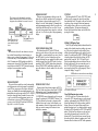
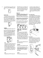
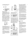
If The Sound is Too Quiet
Check the FOOT CONTROL. There are two foot controller jacks, VOLUME and MODULATION. Two additional jacks are for foot switches, SUSTAIN and
PORTAMENTO. If the foot controller is plugged into the
SUSTAIN or PORTAMENTO jack, it will not work. Also,
when the controller is plugged into the VOLUME jack
and is tilted forward, there will be little or no sound
regardless of how you set the VOLUME control on the
front panel.
Some voices are inherently quieter than others. Often
this is due to the amount of touch sensitivity which may
be programmed into a voice. If the voice is programmed
so that the note will become louder if you press the key
harder, or if you press it faster, then a less vigorous playing style will result in a quieter note. Played the same
way another voice which is less touch sensitive will
sound louder. The voice which is initially louder, however, may not become much louder (if at all) as you play
the notes harder. These qualities are user-programmable, even for the preset voices, as explained elsewhere
in this manual.
Save This Manual
The information in this manual is likely to be useful
for future reference. Even if you feel reasonably familiar
with the instrument, save this manual; reviewing it a
few months from now, after you have had considerable
experience with the DX7, may prove to be very informative.
INTRODUCTION
The DX7 is the world's first fully user programmable
and preset FM digital synthesizer. If you're used to conventional synthesizers, one look at the DX7 will tell you
that something unique has happened. There are no
knobs: just two linear controls, one of which is for volume, an LED digital display a small alphanumeric liquid
crystal display (LCD), and a number of flat panel membrane switches. There are no voltage controlled oscillators, amplifiers or filters (VCOs, VCAs, or VCFs), nor are
there any conventional envelope generators (EGs).
Instead, the DX7 utilizes a totally unique method to
create the richest, most naturally expressive sound available in any electronic keyboard. This special sound
generation technology is called FM Digital Synthesis. FM
Digital Synthesis enables the DX7 to create the overtones that would be present in an actual acoustic instrument, and to vary them over time in a precise,
controllable manner to produce uncanny realism when
you're playing an acoustic voice — or to produce incredible fantasy sounds — the possibilities are without limit.
Because the DX7 creates sounds differently than conventional analog or purely digital synthesizers, you'll
have to spend some time re-educating yourself with the
aid of this manual. After you've become familiar with
the panel, a few new terms, and the general concept of
FM digital synthesis, you'll love the precision and tremendous versatility at your disposal. If you're already an
experienced synthesist, you will soon be able to go right
for a particular sound. Whether you're a beginner or a
world class performer, you can enjoy the large library of
preset sounds that come with the DX7.
The DX7 is delivered ready to play, loaded with 32
beautifully voiced, useful, factory preset sounds. These
sounds can be instantly changed, or can be replaced by
additional factory-supplied sounds from a library of 128
that are supplied on special solid state cartridges. Literally hundreds of exciting sounds can be at your fingertips with just the press a few selector buttons. You don't
have to program a single thing... unless you want to.
Presets won't handle every job, and there's nothing that
says you have to use ours. You can make your own
voices.
The compact size and relatively few controls of the
DX7 can be deceiving. Almost every button and knob
have multiple functions (depending on the selected
operating mode) so that a total of some 168 parameters
can be altered. In fact, the DX7 has more programmability than any synthesizers Yamaha has ever before
offered to the public, providing greater control over the
sound than large or modular systems.
The DX7 keyboard is fully polyphonic with 16-note
simultaneous capability, so the sustain of previous notes
will not be cut short when you're playing with all 10
fingers. It is also highly responsive to player expression.
The harder or faster a key is played, the louder the
initial attack of the note — just like a piano. Unlike a
piano, however, the degree of touch response is programmable... both in sensitivity to the speed (velocity) at
which the key is pressed, and in sensitivity to how hard
you press after the kit hits the stop (after touch).
You can program voices from scratch (using a voice
initialize function). If you like an existing voice, you can
edit it to make subtle changes, or transform its character
completely.
Because the DX7 employs unique FM tone generation
techniques and lets you program them with the precision and repeatability of digital control, you'll be able to
create voices that are a giant step beyond the capability
of former synthesizers. Pure sounds. Richly textured
sounds. Outer space sounds. Bold, heavy sounds. Subtle, delicate sounds. Uncannily accurate acoustic sounds.
All are possible with the high fidelity that FM digital
tone generation can provide.
Once you've edited a voice or created an entirely new
one, you can store it in the internal memory and/or in
special solid state cartridges. A battery prevents loss of
memory — even after the instrument is unplugged from
the AC receptacle.
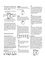
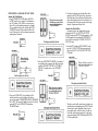
voices 1-32 in Bank A or 1-32 in Bank B — access for
playing, editing, or loading into the synthesizers internal
memories. Before the DX7 is shipped, 32 of the 128
voices called the "Master Group" are loaded from the
bank A of the #3 ROM cartridge into the synthesizer's
internal memories. This means that a cartridge does not
have to be installed in order for you to open the carton,
plug in headphones or an amplifier/speaker system,
turn on power, and begin playing.
You can edit the preset voices, or make voices from
scratch, but you cannot permanently store your own
voices on the ROM cartridges. For this purpose, a third
storage method is provided: an EEPROM (Electrically
Eraseable Programmable Read Only Memory) cartridge
which, for simplicity, we call a RAM cartridge (Random
Access Memory). The RAM cartridges go in the same
slot as the ROM cartridges, and superficially they look
the same. However, because of the added complexity of
RAM memory, only 32 voices will fit in one of these cartridges. The slide switch on the RAM cartridge is actually
an additional "write protect" feature that prevents acccidental erasure of voices you have stored; it is not a bank
A-B selector.
This arrangement lets you have a total of 96 voices at
your fingertips since you can have any 32 voices you
wish loaded in the internal memories, then install one
of the 64-voice ROM cartridges. You switch between
internal and cartridge voices with the press of a button,
and between cartridge banks A & B with a slide switch.
Of course, if you allow for changing cartridges, which
takes just a second, your live performance voice library
is really unlimited.
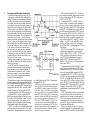
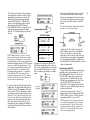
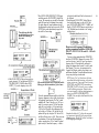
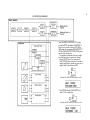
Up to 96 Voices Can Be "On Line" Ready for
Instant Recall
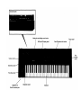
NOTE Portions of the front panel are used to illustrate
Voices (sounds or ''instruments") may be saved in 3
the text throughout this manual; it should be relatively
different ways with the DX7. As mentioned above, the
easy to see where these "spot" illustrations fit in the consynthesizer has 32 internal voice memories that can
text of the entire instrument if you are reading the manhold any combination of factory preset sounds or voices ual with the DX7 in front of you. If the instrument is not
you create. In addition to the internal memories, one of handy we suggest opening this cover fully revealing an
two types of memory cartridges may be inserted in the
overall front panel illustration that will remain visible as
instrument for additional "on line" memory. Pushbuttons you flip through the inside pages. Originally ROM carenable you to select from the internal and cartridge
tridges were numbered #1 & 2. Later models were
voices.
shipped with ROM cartridges #3 & 4 instead. Both sets
A total of 128 factory preset voices are provided. Obvi- have similar voices.
ously they all cannot fit in the 32 internal memories at
once; these voices are actually supplied to you stored in
2 solid state ROM (Read Only Memory) cartridges that
each hold 64 voices, arranged in two banks of 32. You
move a slide switch on the cartridge to gain access to
NOTE FOR SYNTHESIZERS SOLD BY THE U.S.A.
2
Internally, the DX7 generates signals in the radio frequency spectrum. If the instrument is installed
in the immediate proximity of some types of audio or video devices (within ten feet), interference
may occur.
Federal Communications Commission (FCC) Rule Part 15, Subpart J, establishes design and
manufacturing standards that will provide a reasonable level of protection against the possibility
that two electronic devices, operating simultaneously, might interfere with each other.
The DX7 has been type tested and found to be in compliance with the design and manufacturing
standards established for "Class B" computing devices. Compliance with the standards established
by the FCC does not guarantee that interference will be eliminated. If your instrument is suspected
of causing interference with other electronic devices, verification can be made by turning your
instrument on and off. If the interference continues when your instrument is off, the instrument is
not the source of the interference. If your instrument does indeed appear to be the source of the
interference, one or more of the following corrective measures should be tried.
(1) Relocate either the instrument or the electronic device that is being affected by the interference.
(2) Utilize power outlets for the instrument and the device being affected that are on different branch
circuits (different circuit breakers or fuses), or install AC line filters.
(3) In the case of radio or TV interference, relocate the antenna; if the antenna lead-in wire is 300
ohm ribbon lead, change it to 75 ohm co-axial type cable (utilizing the necessary transformer/
adaptors at either end, as required to match the cable).
If these corrective measures do not produce satisfactory results, please ask for suggestions or
seek corrective measures by contacting your Authorized Yamaha Dealer or:
Music Marketing Group
Service Division
Yamaha International Corporation
6600 Orangethorpe Avenue
P.O. Box 6600
Buena Park, CA 90622
If, for any reason, you should need additional information relating to radio or TV interference, you
may find helpful a booklet prepared by the FCC: "How to Identify and Resolve Radio-TV Interference
Problems." This booklet, (stock number 004-000-00345-4) is available from:
U.S. Government Printing Office
Washington, DC 20402
INTRODUCTION
Inside front cover
PRECAUTIONS
Inside front cover
CONVENTIONS
3
"QUICK" BASIC FEATURES
4
SETUP
Audio Output
External Foot Controller Jacks
Breath Controller
MIDI Connectors
AC Power
Installation of Music Rack
Additional Technical Installation Notes
12
12
12
12
12
12
12
13
PLAYING THE FACTORY PRESET VOICES
Playing the Internal Voices
Playing the Cartridge Voices
14
14
14
FUNCTION MODE: SETTING OVERALL
PERFORMANCE PARAMETERS
Data Entry
Function
Poly/Mono
Pitch Bend Range & Step
Portamento Functions
Portamento & Glissando in Poly Mode
Sustain: Key Pitch Retain
Sustain: Key Pitch Follow
Glissando (Key Pitch Retain & Key Pitch Follow)
Portamento & Glissando in Mono Mode
Fingered Portamento (and Glissando)
Full Time Portamento (and Glissando)
MIDI
Edit Recall
Voice Initialize
Cartridge Format
Battery Check
Modulation Wheel
Foot Control
Breath Control
After Touch
15
15
15
16
17
17
18
18
18
19
19
19
19
20
20
20
20
20
21
21
21
21
HOW THE DX7 CREATES SOUNDS
Operators
Carriers, Modulators and FM
Algorithms
The relationship between algorithms and the sound
Feedback is available in every algorithm
Envelopes and Envelope Generators
23
23
23
24
24
25
26
PROGRAMMING VOICES: A TUTORIAL
Two basic approaches to creating your own sounds on
the DX7
Programming a voice "from scratch"
Voice Initialization
What is initialization?
How to interpret the display
Looking at the initial EG settings
Experimenting with the EG
Learning to change the operator FREQUENCY settings
How to create Frequency Modulation: getting acquainted
with the OPERATOR SELECT OUTPUT LEVEL
and ON-OFF edit features
Additional editing features: ALGORITHM SELECT
KEYBOARD RATE SCALING and LEVEL SCALING
LFO Modulation: The relationship between the "LFO"
settings and the "MOD SENSITIVITY" settings, and
how to program these
Programming the remaining 4 operators
Programming velocity sensitivity
Naming and storing the newly created voice
Edit Recall "Emergency Voice Recovery" instructions
27
EDITING A VOICE
Analyzing and keeping a record of voices
27
27
27
28
28
28
29
31
33
38
40
44
45
45
46
47
48
THE INTERNAL AND CARTRIDGE MEMORIES
Memory Protect
Storing individual voices to RAM cartridge
Saving all 32 internal memory voices to RAM cartridge
Loading all 32 ROM or RAM cartridge voices to internal
memory
Transfering a single voice from one location to another in
the RAM cartridge or internal memory
ADVANCED PROGRAMMING NOTES
Playing style and programming of dynamic control
Additional envelope considerations
Delayed turn-on using the envelopes
How to select an algorithm
Leam to program by studying how acoustic instruments
work
There is more than 1 way to create a pitch
Ensemble voices may differ from solo voices
Breath controller applications and hints
Special effects from [DATA ENTRY] while in PLAY mode
Reference sources on FM synthesis
49
49
49
49
49
49
51
51
51
51
51
52
52
53
53
53
54
MIDI: A STANDARD INTERFACE FOR REMOTELY
PLAYING AND/OR PROGRAMMING MULTIPLE
SYNTHESIZERS
MIDI connections
Transmitting 32 voices from the Master to the Slave
Playing the Slave from the Master
Transmitting individual voices from the
Master to the Slave
Using DX7 RAM cartridges to save DX9 voices
Programming remotely with MIDI
Escaping from MIDI control
A special setup with two Masters and no Slave
More information on MIDI
56
57
57
57
57
57
MAINTENANCE AND TROUBLESHOOTING
Cleaning
Internal Memory Battery Backup
If something goes wrong
58
58
58
58
DX SYNTHESIZER GLOSSARY
59
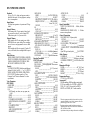
SPECIFICATIONS
63
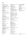
INDEX
64
55
55
56
56
CONVENTIONS
Nearly every button on the DX7 has several functions.
Typically, the editing parameters are labeled in violet,
the overall instrument functions are labeled in brown,
and yet other functions are labeled in white or by
reversing out the color of the button. Since this manual
is not printed in full color, we have adopted the following conventions when referring to buttons. First, even
though the button has several labels, we name only the
button label which applies to the particular step being
discussed. That button name will be bracketed to denote
a button. In addition, in many cases we actually illustrate
the button so there is no confusion as to which control
is being discussed.
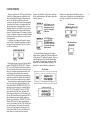
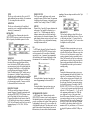
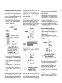
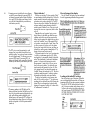
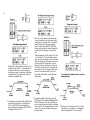
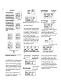
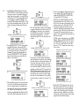
Lets look at a few examples to illustrate the conventions. Find the 32 numbered green buttons, and look at
the upper left corner of that area. This is how we illustrate the first two buttons:
Both buttons are part of a group of 6 that are labeled
in violet "OPERATOR ON-OFF/EG COPY". When the
DX7 is in the EDIT mode, this label indicates that two
different functions can be selected or activated by each
button: (a) turning the output of an operator on or off,
and (b) copying an envelope from one operator to
another. Don't worry about what this means right now;
we describe operators and envelopes and so forth later.
Suffice it to say there are multiple uses for the buttons.
To continue, when we are discussing the left button in
the context of (a) above, the printed reference to the
button looks like this: [OPERATOR ON-OFF 1]. The
same button, used in context (b), is described like this:
(EG COPY 1]. When the DX7 is in the FUNCTION
mode rather than the EDIT mode, the brown label
below it applies instead of the violet label above it. In
this case, the identical button now prepares the DX7 so
that its master tuning can be adjusted, and the text
describes the button like this: (MASTER TUNE ADJ.).
When the DX7 is in PLAY mode, the green buttons
serve as Voice Selectors. The label "Voice Selector" does
not actually appear on the front panel, but when the
text asks you to play internal or cartridge voice #1 by
pressing Voice Selector [1], the #1 green button is the
correct choice. As you can see, the text reference
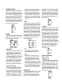
changes to suit whichever of the button's several functions is under discussion, yet the button is always illustrated the same way:
In EDIT mode, press the
[OPERATOR ON-OFF 1]
illustrate two or more adjacent panel buttons, whereas
in other cases we illustrate just one; the multiple buttons
are to help you identify the one button we are discussing.
This illustration
button once to turn off
operator #1 and again
to turn it on.
In FUNCTION mode,
press the [MASTER
TUNE ADJ] button to set
the [DATA ENTRY] slider
so it can alter the tuning
of the keyboard.
We alternate between showing you the complete
display window, including the LED voice number readout, and just the LCD portion of the display. There is no
particular signficance to this; the abbreviated display
saves space on the printed page, and when we don't
consider the voice number readout significant for an
instruction, we omit it. Similarly in some cases we
This illustration
is the same as this one
is the same as this one
3
"QUICK" BASIC FEATURES
4
This section is provided for reference so you
can quickly locate a control or access a function.
It is meant more for review than as a learning
tool. If this is your first time reading the manual,
we suggest you either skim this section, or skip
it altogether and go on to the section titled "Playing the Factory Preset Voices".
The DX7 has 3 basic operating modes:
• PLAY (MEMORY SELECT) Mode
This is the "normal" performance mode in which preprogrammed voices can be selected.
•EDIT mode
This mode is used to edit an existing voice or to create
an entirely new voice. Some of the "editing" functions
do not alter the structure of the voice directly yet can
have a major effect on the sound: for example, changing the sensitivity of a given voice to various modulation sources, transposing the voice, or changing the
keyboard scaling.
• FUNCTION mode
This mode is used to adjust parameters that affect
more than 1 voice, including the effect of the Modulation Wheel, Foot Controller, Breath Controller and
After Touch (pressure sensitivity). FUNCTION mode
also provides access to certain utility functions such as
loading voices from a cartridge, saving voices onto a
cartridge, checking the internal backup battery voltage, and initializing the instrument when you want to
program a voice "from scratch" (which then automatically places the instrument in EDIT mode).
The DX7 front panel is unlike any conventional synthesizer. There are many more functions than buttons. It
is important to bear in mind that the [DATA ENTRY]
controls are assignable by means of the other buttons on
the DX7. They take the place of the many knobs and
sliders on conventional synthesizers. Another thing to
remember is that, depending on the operating mode,
the front panel controls may be used in different groupings. For example, in one place we may refer to VOICE
SELECT button [1]. This is the same physical button as
[OPERATOR ON-OFF 1] and the [MASTER TUNE]
function selector. The 2 rows of 16 buttons at the right of
the synthesizer are, among other things, the [VOICE
SELECT] buttons. They include large white numerals
[1] to [32], which apply when the buttons are used to
select voices from the correspondingly numbered internal or cartridge memories. Many of the buttons include
a small letter, number, or word at the right, inside edge.
These are used for labeling voices, as explained in the
[VOICE NAME] button description.
NOTE Refer to the illustration in the foldout front
cover to identify the following features.
Rear panel connectors
These jacks include the line level output from the
DX7 to an amplifier, foot control jacks, and MIDI interface
connections. Refer to the "Setup" and "MIDI" sections of
this manual for details.
Volume and Data Entry Controls
VOLUME
This adjusts the overall output level at the rear panel
OUTPUT jack and the front panel HEADPHONE jack.
Some presets are inherently louder than others, and this
can be used to compensate, or to do overall fades. If
volume is too low, and the foot controller is plugged into
the VOLUME jack, make sure the pedal is tilted flat for
maximum level. It is also possible that amplitude modulation sensitivity has been programmed into a voice, in
which case, to make the voice play louder, you may
want to use the MODULATION WHEEL, BREATH CONTROLLER, FOOT CONTROLLER (plugged into the
MODULATION jack), or the AFTER TOUCH (pressing
harder after the key hits bottom). See the FUNCTION
mode information on page 10 for more information on
these modulation controls.
For example, if the DX7 asks you "are you sure", you
can reply [NO] or [YES] with the left and right buttons.
If you want to turn the glissando or some other programming function on or off, the [OFF] and [ON] labels
apply — same buttons. If you want to change the frequency ratio or some other programming value by one
unit at a time, the [-1] and [ +1] labels apply. If you just
want to move the cursor to a different position when
naming a voice, the [<] (move left) and [>] (move right)
labels apply Usually you will be able to get the same
effect by moving the adjacent slider up and down.
These controls are used primarily in the FUNCTION
and EDIT modes, but also continue to modify the last
selected FUNCTION parameter after returning to the
PLAY mode (MEMORY SELECT INTERNAL or CARTRIDGE).
These buttons are for increas-
ing or decreasing the values by
1, for turning a function on or
off, and for moving the cursor
when writing a voice name.
This slider is used for rapid or large changes. Moving it
all the way down and up covers the full range available
for each parameter.
Mode Select and Editing Control Section
These buttons let you see & change the MEMORY
PROTECT status -
DATA
This group of a slider and two buttons serve as the
main programming controls for the DX7. The two green
buttons are single-step increment/decrement controls
that do the same thing as the slider; the slider is faster
for large changes and the buttons are better for small
adjustments.
Each of the buttons has four different labels. The
specific labels apply to different programming functions.
This button is used for
copying EG data and for
storing individual voices on
an internal or RAM cartridge memory
This button selects the
current operator (the one
being adjusted) when the
synthesizer is in edit mode
These buttons select the internal or cartridge
memory and activate the PLAY mode; they also
designate where individual voices may be stored
This button selects the
EDIT mode and compares edited to original
voices
OPERATOR SELECT
When you are programming or editing a voice, this
button lets you select the operator which is to be modified, as shown in the upper right corner of the LCD
display. (It sets the "current operator".) Remember that
some programming parameters affect the overall voice,
in which case this button will have no effect. You can
only select from operators that are turned on, as shown
by the six 1's or 0's in the top line of the programming
display.
FUNCTION
This button places the DX7 in the FUNCTION mode,
which is used to program the entire keyboard rather
than individual voices. This mode is also used for checking battery voltage, storing all the internal memories
onto cartridge at once, and vice-versa, and a few other
specialized functions. The functions designated by
brown labels beneath other buttons are available after
pressing this button.
EDIT/COMPARE-CHARACTER
This button places the DX7 in the EDIT mode,
wherein you can edit any of the preset voices to change
them slightly, or create completely new voices. Once in
the EDIT mode, if you have changed a preset, then
pressing this button lets you compare the edited version
with the original. Once in the EDIT mode, if you have
pressed the [VOICE NAME] button, then pressing this
button [CHARACTER] and holding it enables you to
press other buttons to enter the name of the voice in the
display
LED & LCD Display Panel
The LED (Light Emitting Diode) window indicates the
number of the selected internal or cartridge voice memory. If the voice being played is in the midst of being
edited, a decimal point appears to the right of the voice
number. If you then press the [EDIT/COMPARE] button
to hear the original voice before the editing, the LED
numbers blink on and off. The LCD (Liquid Crystal
Display) window displays the current status of the synthesizer, which may be the voice name and source, or
the FUNCTION or EDIT mode parameter which was
most recently selected. Refer to the paragraph "How to
interpret the display," on page 28.
LCD synthesizer stains and voice name display
This button selects the
FUNCTION mode
STORE
This button can be used to store whatever voice you
have selected from cartridge or internal memory, or
whatever voice you have just programmed. A voice can
be stored into any of 32 internal memories or into any
of the 32 memories in a RAM cartridge (provided the
memory protect is turned off). This button is also used
in conjunction with the [EG COPY] buttons for copying
envelopes from one operator to another.
MEMORY PROTECT
This pair of buttons enable you to set the internal and
cartridge memories so that voices cannot be accidentally
erased. When you press one of the buttons, the display
shows you whether the associated memories are
protected or not, and you can use the[DATA ENTRY]
controls to change the status. Remember, however, that
even if you turn off the cartridge memory protect, you
still cannot save a voice on a ROM cartridge, nor can
you save a voice if the On/Off switch on the RAM cartidge itself is set to the ON position.
MEMORY SELECT- PLAY
Pressing either of these buttons prepares the DX7 to
PLAY any of the voices that are stored in the 32 INTERNAL memories, or in 32 memories of whatever CARTRIDGE is installed. Once the [INTERNAL] or
[CARTRIDGE] source is designated, specific voices are
accessed by pressing the VOICE SELECT buttons [1] to
[32]. These buttons are also used to designate where
individual voices can be stored, in the internal or cartridge memories, either after being created or edited, or
when you want to rearrange the location of voices
within these memories.
Voice number LED display
Voice/Edit/Function select section
In PLAY mode. these 32 buttons select either the
voices in the DX7's internal memory or on the external
cartridge, as determined by the [MEMORY SELECT]
buttons and indicated by the large numbers inside the
buttons. However, these same buttons actually have
multiple functions (up to 5 per button) which are accessible when the DX7 is placed in the FUNCTION and EDIT
modes. All labels on these buttons are color and position coded: white numbers on the inside left of the
buttons for PLAY mode, dark brown (reversed) type on
the inside right of the buttons for naming voices, violet
characters above the buttons for EDIT mode parameters,
5
6
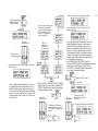
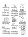
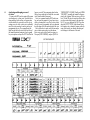
and light brown characters below the buttons for FUNCTION mode parameters. A brief example for two buttons
is shown here, with the specific references for these two
buttons noted in parentheses:
ALGORITHM
In EDIT mode, this button activates the [DATA
ENTRY] section so its controls can be used to select any
of the 32 available algorithms.
Violet EDIT mode parameters (Pitch and Amplitude
Modulation Sensitivity)
White PLAY mode
voice number (15
&16)
Reverse printed
EDIT mode Voice
Name character
(E&F)
Brown FUNCTION mode parameters (SAVE all 32
voices from internal memory to cartridge, or LOAD 32
voices from cartridge to the internal memory)
To simplify the presentation, we have further subdivided these buttons into the EDIT (violet) and FUNCTION (brown) groupings. Therefore, if you don't see the
operational description that applies to what you're doing
with a particular button as you read through the paragraphs on the EDIT parameters, check the corresponding button in the FUNCTION parameter descriptions
(and vice-versa).
Edit Parameter Selection (violet labels)
OPERATOR ON/OFF-EG COPY (1-6)
These buttons have two functions, (a) to turn individual operators on and off while you are programming a
voice, and (b) to designate the operator into which you
wish to copy an envelope. When you are in the EDIT
mode, the top center portion of the LCD display shows 6
number 1's or 0's, corresponding to the 6 operators:
1 =ON, and 0=OFF To toggle operator's output on or
off, press the corresponding [OPERATOR ON-OFF]
button. To copy the envelope, set the operator whose
envelope you wish to copy as the current operator using
[OPERATOR SELECT], then press [STORE] and hold
it while pressing [EG.COPY] button for operator 1 to 6;
all 4 rates and levels are instantly copied.
FEEDBACK
In EDIT mode, this button activates the [DATA
ENTRY] section so its controls can be used to alter the
amount of feedback in whatever algorithm is displayed
from none (0) to a maximum value (7).
LFO
In EDIT mode, these 6 buttons each activate the
[DATA ENTRY] section so it can be used to program or
edit individual voices with regard to Low Frequency
Oscillator modulation. When the modulation is used to
change the pitch, vibrato can be obtained. When it is
used to change the amplitude of a carrier, tremolo may
result; changing the amplitude of a modulator can create
"wah-wah."
WAVE
This lets you set the LFO waveform to any of the
following: triangle, sawtooth down, sawtooth up,
square, sine, sample & hold.
SPEED
This lets you adjust the LFO frequency in a 100 step
range, 0 being the slowest and 99 the fastest.
DELAY
This lets you set the LFO so modulation does not
begin until after a specified time after you press the
key, 0 being no delay, and 99 the maximum delay.
PMD
This lets you set the Pitch Modulation Depth. This is
the amount of modulation that will be applied to shift
the pitch of whatever notes are played (according to
the set waveform and speed). However, the modulation can only affect the note if the pitch modulation
sensitivity is set to a value greater than zero (see
[MOD SENSITIVITY-PITCH]).
AMD
Like PMD, this button lets you set the Amplitude
Modulation Depth, the amount of modulation that
will be applied when you play but it affects the
amplitude (level), not the pitch. Likewise, the modulation can only affect the note if the Amplitude modulation sensitivity is set to a value greater than zero
(see [MOD SENSITIVITY-AMPLITUDE]). The same
LFO speed and waveform controls both the [PMD]
and [AMD].
SYNC
This lets you turn on or off the LFO Key Synchronization. When Sync is ON, the LFO is automatically
reset to the beginning of the selected waveform each
time you play a note. When sync is OFF the LFO
waveform continues, and when you play a note, the
result will vary depending on where the LFO is in
the cycle. The effect can be easily detected at low
LFO frequencies (SPEED settings below 10).
MOD SENSITIVITY
In EDIT mode, this pair of buttons activate the [DATA
ENTRY] section so it can be used to set the sensitivity
of individual voices to LFO modulation. The modulation
sensitivity is like a master control for all the modulation,
whether it is "built into" the voice with the adjacent
[AMD] and/or [PMD] buttons, or whether it comes from
the "real time" modulation controls such as the Modulation Wheel, the Foot Control, the Breath Control or the
keyboard After Touch. If the Pitch or Amplitude Modulation Sensitivity is set at zero, then none of the external
controllers can affect the voice, regardless of how much
Depth is set with their FUNCTION mode controls.
PITCH
This lets you set the sensitivity of the voice to LFO
pitch modulation from no sensitivity (0) to maximum
(7). One setting affects the overall voice.
AMPLITUDE
This lets you set the sensitivity of the individual
operators in a voice to amplitude modulation from no
sensitivity (0) to maximum (3).
OSCILLATOR
In EDIT mode, these 4 buttons each activate the
[DATA ENTRY] section so it can be used to program or
edit the frequency of individual operators in a voice.
MODE/SYNC
The DX7 toggles between two different programming
functions when you press this button successive
times. One function, MODE, enables you to set the
current operator so it tracks the keyboard pitch (this
is Frequency Ratio Mode), or so the keyboard does
not affect that operator's frequency (Fixed Pitch
Mode). The other function, SYNC, enables you to set
the operator so its "oscillator" begins at the start of
the sine wave cycle each time you play a note. When
Oscillator Key Sync is OFF, the sine wave continues
so that subtle differences will occur even when you
play the same note repeatedly. You may not be able
to hear much difference in some voices.
FREQUENCY COARSE
This lets you make large changes in the current
operator's frequency It operates in conjunction with
the adjacent [FREQUENCY FINE] button. Assuming the Fine setting is all the way down, then in
Frequency Ratio mode the ratio increases from 0.50
to 1.00 and then by integer values to a maximum of
31.00. In Fixed Frequency mode, this lets you set the
beginning frequency to 1 Hz, 10 Hz, 100 Hz, or
1000 Hz.
FREQUENCY FINE
This lets you make small changes in the current
operator's frequency With this control, the maximum
available increase in frequency is just under the next
available "Coarse" setting (1.99 times "F COARSE").
DETUNE
Detune is like a "super fine" frequency adjustment for
each operator. You can shift the frequency over a
range of -7 to +7. Mild detuning can enrich the
harmonic structure and more closely simulate the
imperfect nature of a real acoustic instrument. Maximum detuning between carriers can be used to cause
"beating" within a voice to help simultate chorusing
or multiple instrument effects.
EG
In EDIT mode, this pair of Envelope Generator buttons activate the [DATA ENTRY] section so it can be
used to program or edit the envelopes of individual
operators in a voice. 4 parameters are programmable
with each button, and the range of adjustment is from
the minimum of 0 to a maximum of 99 (100 steps).
RATE
Pressing this button 4 successive times gives you
access to programming the 4 rates in the EG.
LEVEL
Pressing this button 4 successive times gives you
access to programming the 4 levels in the EG.
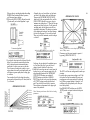
KEYBOARD LEVEL SCALING
In EDIT mode, these 3 buttons each activate the
[DATA ENTRY] section so it can be used to program or
edit individual operators so their output levels change as
you play up and down the keyboard. Each operator can
be programmed to have any of 4 curves on either side
of an adjustable break point. The scaling can be used to
make the tone and/or volume change as you move to
different octaves, for more realistic acoustic instrument
simulations. Extreme settings can also be used for "split
keyboard" effects.
BREAK POINT
The level can be scaled up or down differently on
either side of the Break Point in the curve. You can
set this break point from 1-1/3 octaves below the
lowest key on the keyboard (A -1) to 2 octaves above
the highest note on the keyboard.
CURVE
Pressing this button successive times gives you access to programming the scaling curve for the left or
right side of the break point. Either curve may then
be set to any of four characteristics: negative linear,
negative exponential, positive exponential, positive
linear. The linear curves will give you a more exaggerated boost or cut in level at any given depth setting as you play up and down the keyboard, where as
the exponential curves tend to give more natural
sounding scaling.
DEPTH
Pressing this button successive times gives you access to programming the depth of the selected left or
right curve. At a minimum setting (0), there is no
scaling, and you can increase or decrease the level
up to a maximum of 99. To increase the level, there
has to be some "headroom," some operator output,
level available for increase. For example, if the OPERATOR OUTPUT LEVEL is set at 90, and a positive
(+) curve is set, the greatest curve depth that can be
achieved is 9. This is because 90 + 9 = 99, and 99
is the maximum possible output level. While the
curve depth can be set to a value greater than 9.
there will be no more effect than if it were set at 9; if
you want more boost as you move up or down the
keyboard, then you'll have to set the Operator Output Level at a lower value so that more "headroom"
is available for the scaling to boost the level to the
maximum of 99. For your reference, a -L1N curve set
to a depth of 99 produces a roll-off of 22 dB per octave.
7
8
KEYBOARD RATE SCALING
In EDIT mode, this button activates the [DATA ENTRY] section so its controls can be used to program or
edit each operator so its envelope rates become faster as
you move up the keyboard. The minimum setting (0)
produces no scaling, so rates Rl, R2, R3 and R4 are the
same on all keys, whereas the maximum setting (7)
speeds up the rates more and more as you move from
the lowest to the highest notes. The scaling is useful for
simulating the natural scaling of envelope rates that
characterizes many acoustic instruments.
OPERATOR
In EDIT mode, this pair of buttons activate the [DATA
ENTRY] section so its controls can be used to change
the output level of each of the 6 operators.
OUTPUT LEVEL
This button gives you "direct" programming access to
setting the output level of each operator from no
output (0) to maximum (99). Remember that the
[OPERATOR ON- OFF] buttons only have an effect
while you are programming a voice so if you want to
keep an operator turned off when you store a voice
(because you don't need its effect), then you have to
set its output level to zero. The scaling is such that
half the numerical value (i.e. 50 instead of 99)
produces much less than half the audible volume.
KEY VELOCITY SENSITIVITY
This button lets you program the velocity "touch"
sensitivity of each operator so that the faster you
press a key the greater the output level. This function
interacts with the [OUTPUT LEVEL] function so
that, if you set a maximum [KEY VELOCITY SENSITIVITY] of 7, and then press a key very slowly
there will be virtually no output from the operator;
press that key fast, and you'll get the maximum
output level you have set with [OUTPUT LEVEL]. If
the operator is a carrier, this function causes the
notes to be louder when you play faster, whereas if
the operator is a modulator, the timbre changes as
you play faster. This is the parameter that determines
why some preset voices have touch sensitivity and
others do not.
PITCH EG
In EDIT mode, this pair of buttons activate the [DATA
ENTRY] section so its controls can be used to change a
special envelope generator that alters the frequency of
each note you play. The Pitch EG affects all 6 operators
equally. The "shape" of the envelope follows the same
rules as the individual operators' level envelopes, with
four rates and four "levels", although the levels actually
refer to frequency excursions. The Pitch EG can be used
for automatic pitch bending effects, including the slight
pitch changes that occur with plucked strings. However,
the 8 octave range of this feature permits all sorts of
special effects to be achieved.
so that middle C (C3) is 262 Hz. When you press [KEY
TRANSPOSE], the first key you then press becomes
the pitch which is produced when you play middle C
(you won't hear anything until you play a subsequent
note). The transposition range is great enough that middle C can be set to sound the pitch of any note for 2
octaves up or down.
VOICE NAME
In EDIT mode, this button DOES NOT RELY ON THE
[DATA ENTRY] section either. Instead, it converts the
[EDIT/COMPARE] button to the (CHARACTER] button so you can enter up to 10 letters, numbers, spaces
or punctuation marks to name a voice. Once you've
pressed [VOICE NAME], you hold down the [CHARACTER] button and then press each character you wish
to enter (indicated by the reversed dark brown type in
the right corner of most buttons). A flashing "cursor"
shows you the position of the character you are about to
enter, and you can move the cursor without entering a
character by pressing the [<] and [>] buttons. You can
"write" new-characters on top of previous names, or
erase a name by using the [CHARACTER] and
[SPACE] buttons.
RATE
Pressing this button 4 successive times gives you
access to programming the 4 rates in the EG.
LEVEL
Pressing this button 4 successive times gives you
access to programming the 4 "levels" in the EG. If
you don't want any pitch bend, then all 4 levels
should be programmed to a value of 50. When you
set a level below 50, the pitch decreases (a zero value
is down 4 octaves from the note you play), and when
you set it above 50, the pitch increases (a 99 value is
up 4 octaves). The [PITCH] wheel can further add 1
octave above or below this "automatic" pitch bend.
KEY TRANSPOSE
In EDIT mode, this button DOES NOT RELY ON THE
[DATA ENTRY] section. Instead, it activates the keyboard so it can be used to transpose the pitch of the
entire voice. The "normal" pitch of the keyboard is set
Function Control Parameters
(light brown labels)
MASTER TUNE ADJ
In FUNCTION mode, this button activates the [DATA
ENTRY] slider so it can be used to tune the overall
pitch of the keyboard plus or minus 75 cents. (The [-1]
and (+1] DATA ENTRY buttons are not used in this
case because the tuning adjustment is already very fine.)
Larger pitch shifts can be programmed into a voice by
using the [KEY TRANSPOSE] button or by resetting
the frequencies of all operators.
POLY/MONO
In FUNCTION mode, this button activates the [DATA
ENTRY] section so its controls can set the keyboard to
play polyphonically (up to 16 notes simultaneously) or
monophonically (one note at a time).
PITCH BEND
In FUNCTION mode, this pair of buttons activate the
[DATA ENTRY] section so its controls can program the
range and "smoothness" of the [PITCH] wheel. If the
RANGE is set to zero, the [PITCH] wheel will have no
effect.
RANGE
This lets you program the maximum amount of pitch
bend from no effect (0) to plus or minus an octave
(12 semitones). The numbers in the programming
display indicate how many semitones the wheel can
change the pitch in each direction. The [RANGE]
may only be adjusted when the [STEP] is set to zero.
If [STEP] is at 1 or higher, the [RANGE] is automatically fixed at 12 semitones. Remember that a zero
setting turns off the pitch bend.
STEP
This permits you to set the size of the increments by
which the wheel changes the pitch. A setting of zero
(0) will cause perfectly smooth pitch bending. Each
unit above zero represents the number of semitones
by which the pitch will "jump" as you move the
wheel. The maximum setting of 12, for example, will
cause the wheel to change the pitch in a single,
1 octave jump.
PORTAMENTO
In FUNCTION mode, these 3 buttons activate the
[DATA ENTRY] section so its controls can be used to
set portamento (glide) and glissando (stepped glide)
effects, and to control certain sustain characteristics of
the keyboard. The particular effects available will
change, depending on whether the DX7 is in Poly or
Mono mode.
MODE
When the keyboard is in Mono mode, this lets you
select "FINGERED PORTA" or "FULL TIME PORTA"
functions. Fingered Portamento is a glide that occurs
only when you hold one key down and then press
another while holding the first. Full Time Portamento
gives you the glide from one note to the next even
when you release one key before pressing the next.
When the keyboard is in Poly mode, this lets you
select "SUS-KEY P FOLLOW" or "SUS-KEY P
RETAIN". In Sustain-Key Pitch Follow mode, if you
play a note or chord and then play another note or
chord, the sustain from the original note/chord glides
to the pitch of the most recently played note/chord.
In Sustain-Key Pitch Retain mode, the pitch of the
new note or chord glides from that original pitch(es)
without disturbing the sustain of the original note or
chord.
GLISSANDO
When the Glissando feature is turned ON, the glide
in pitch occurs in discrete steps. This effect is best
heard with a slower rate and when two widely separated notes are played one after the other. When
Glissando is turned OFF then normal Portamento
(continuous glide) is available.
TIME
This sets the time of the Portamento or Glissando
effect. A setting of 0 produces no effect, while a setting of 99 produces the longest (slowest) pitch
changes. This is contrary to the operation of most DX7
rate controls whose fastest setting is 99. You don't
have to change the Time to zero to turn the effect off.
Instead, once an effect is selected, it can also be
turned On and Off by plugging an FC-4 or FC-5 foot
pedal into the PORTAMENTO jack on the rear panel;
stepping on the pedal then turns ON the portamento.
NOTE: For [MIDI] information, see page 55.
EDIT RECALL
This button activates the DATA ENTRY [YES] and
[NO] buttons so they can be used to recall a voice that
you had been editing in the event you inadvertently
leave the editing mode and select another voice to play
To "recapture" or recall the edited voice, press [FUNCTION], then [EDIT RECALL], then answer [YES] to the
two display prompts "Edit Recall?" and "Are You Sure?"
VOICE INIT
The Voice Initialize button lets you create a neutral
starting point for programminq a new voice. After you
select VOICE INIT from the FUNCTION mode by pressing the button and then answering [YES] to the two
display prompts, the DX7 sets itself to the EDIT mode. A
neutral "voice" then exists with no modulation, algorithm 1, operator 1 output level at 99 and all others off,
"square" envelopes, and all frequency ratios at 1.00.
CART FORM
NOTE: Since the format of a RAM cartridge used for
other purposes, such as DX1 performance memories,
will vary' from that of a cartridge used for voice memories, make sure you observe the following procedure
when storing or saving DX7 internal voices into such a
cartridge.
The Cartridge Format button lets you "initialize" all
the voices in a RAM cartridge much like you initialized
the single voice in the edit buffer using the [VOICE
INIT] button. It is like a cartridge "eraser." To use this
function you first have turn off the hardware memory
protect switch on the cartridge, then turn off the software [MEMORY PROTECT-CARTRIDGE] function
on the DX7. Then press [CART FORM] and answer
[YES] to the two displayed prompts. THINK BEFORE
YOU DO THIS; IF THERE WERE ANY VOICES YOU
WANTED ON THAT CARTRIDGE, THEY WILL BE
GONE FOREVER. (You can load one or more cartridge
9
10
voices into the DX7 internal memory and then format if
you like.) You cannot format a ROM (factory preset) cartridge.
BATTERY CHECK
In function mode, this button causes the display to
show the voltage level of the battery which preserves
the DX7 internal voice and programming memories
when power is turned off. The acceptable range is 2.3 to
3.5 volts. If the battery is below 2.2 volts, contact your
Yamaha dealer to arrange for replacement; this is NOT a
do-it-yourself repair.
CARTRIDGE
This pair of buttons sets the DX7 to transfer a full 32
voices between the internal and the cartridge memory
Before voices can be transferred TO a cartridge or TO
the DX7, the corresponding (MEMORY PROTECT)
features must be turned off. (Individual voices can be
transferred by first using the Play mode to "pick" the
voice, then pressing the [STORE] button and whatever
Voice Selector you like from 1 to 32.)
SAVE
Pressing this button in FUNCTION mode stores all 32
internal memories to a RAM cartridge. You have an
opportunity to cancel the command by answering
[NO] to either displayed prompt; otherwise any
voices in the cartridge will be erased when the tranter occurs. The display shows "Under Writing" for 20
seconds while the voices are being "written" to the
cartridge.
LOAD
Pressing this button in FUNCTION mode loads 32
RAM or ROM cartridge voices into the DX7 internal
memories. Again, you have to answer [YES] twice
before the voices are loaded (which erases any existing voices in the internal memories). The actual
transfer occurs instantaneously
MODULATION
The bottom row of 16 Function buttons is used to set
the Modulation available from 4 control sources: the
MODULATION WHEEL, FOOT CONTROL, BREATH
CONTROL and key AFTER TOUCH. Since the 4 groups
are identical in nature, we'll cover the buttons just once.
Pressing any of these buttons activates the [DATA ENTRY] section so you can program different settings.
NOTE: if the Amplitude or EG Bias is turned On, with a
low Range setting, certain voices may be inaudible or
nearly so due to their high modulation sensitivity.
level with the corresponding modulation control
(Foot, Breath, etc.). In this case, the LFO is not involved. Again, this will produce changes in brilliance
or volume or "wah" depending on the amplitude
sensitivity programmed into each operator in the
voice.
Voice Cartridge socket
This socket accepts the ROM cartridges which each
hold 64 pre-programmed voices (two are supplied with
the DX7), or the RAM cartridges which each hold 32
user-programmed voices. A protective door automatically swings away when a cartridge is inserted. The
cartridges have a slot in their end connector, and the
socket has a keyway so that the cartridges can only be
inserted fully when properly oriented. If a cartridge does
not seat properly turn it around and try again. DO NOT
FORCE a cartridge into place.
RANGE
This lets you program the amount of modulation
from none (0) to a maximum value (99). Bear in
mind, however, that the Pitch and Amplitude modulation "range" may be zero (off) even if this control is
set at 99 unless the particular voice being played
includes some modulation sensitivity. Since sensitivity Power Switch
This rear panel switch turns power on, permitting
differs between voices, the identical Range setting
the DX7 to be played and/or programmed. The intermay produce different results with different voices.
nal voices are preserved even when power is turned
PITCH
off, so long as the internal battery can deliver at least
This lets you turn On LFO modulation of the voice's
2.3 volts (which can be verified by selecting the
pitch for vibrato-like effects.
FUNCTION/Battery Check mode).
AMPLITUDE
This lets you turn On LFO modulation of the amplitude (level) of those individual operators within a
voice that are programmed to be sensitive to it. The
effect may therefore be tremolo-like, or wah-like
depending on whether a carrier or modulator is
being modulated.
EG BIAS
This lets you directly control the operator output
Keyboard
This is a 61-key keyboard which has initial (velocity) and after (pressure) sensitivity, although these
parameters must be programmed into the voice in
order to be useable. The keyboard has 16-note polyphonic capability or can be switched to monophonic
mode. The overall keyboard pitch produced can be
altered + 75 cents using the Master Tune Adjust
parameter in FUNCTION mode, and the pitch of a
particular voice can be transposed over a 4 octave
range using the Key Transpose parameter in EDIT
mode. Each voice also may have an inherently
higher or lower pitch depending on the frequency
settings of components within the voice (the Operators).
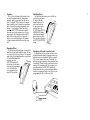
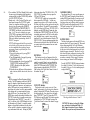
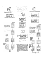
Pitch Bend Wheel
The Pitch Bend wheel permits you to shift the keyboard pitch up and down;
the range of this shift
depends on how far the
wheel is deflected from
the spring-return center
position, and on the
FUNCTION mode [PITCH
BEND RANGE] setting,
with a maximum range of
plus or minus one octave.
The smoothness depends on
the [PITCH BEND STEP]
setting.
Modulation Wheel
The Modulation wheel permits you to introduce LFO
modulation of pitch and/or amplitude and/or EG bias
as you move the wheel away from you. The range and
nature of the effect obtained depends on several factors
(1) how the Modulation Wheel
parameters are set in
FUNCTION mode, and (2)
whether the voice has modulation sensitivity programmed
into it; if either factor is
not set appropriately the
wheel will have no effect.
Headphone & Breath Controller Jacks
The Headphone jack lets you listen without an external amplifier/speaker system by plugging in almost any
pair of mono or stereo headphones that has a standard
1/4" (6.3 mm) diameter phone plug. The Breath Controller jack accepts the miniature stereo phone plug from
a Yamaha BC-1 Breath Controller, which may be used to
introduce LFO modulation or EG bias into most voices
depending upon how the FUNCTION mode Breath
Control parameters are set, and on whether modulation
sensitivity is programmed into the voice. (If they are not
set appropriately the BC-1 will have no effect.)
11
SETUP
12
NOTE: Do not turn power On until all other connections
have been made.
goes into the BREATH CONT. jack on the front of the
DX7; DO NOT plug anything else into this jack.
Audio Output
The DX7 has a built in headphone amplifier, so
stereo headphones may be plugged into the front
panel jack. However, the instrument does not have a
built in power amplifier, and thus requires an external amplifier/speaker system. The OUTPUT jack is
suitable for connection to any unbalanced, low line
level input. This includes the input of the self-powered speaker systems, and the 600 ohm or higher
impedance line inputs of any Yamaha mixer. Remember (hat the audio output level not only depends on
the VOLUME setting, but also on the selected voice,
the playing style, and the position of the foot control
if it is plugged into the VOLUME jack.
Use a single conductor shielded cable with a standard
1/4" (6.3 mm) tip/sleeve phone plug. Coiled guitar
cords are not recommended since they typically degrade
the high frequency response more than a straight cord.
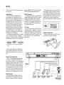
MIDI Connectors
These multi-pin DIN connectors are for the Musical
Instrument Digital Interface system (MIDI), a standard
adopted by several leading synthesizer manufacturers. MIDI allows the DX7 to remotely control (or be
controlled by) other keyboards, sequencers and computer interfaces. See the "MIDI" section of this manual for additional information.
Standard guitar cord, 20 feet maximum recommended
length.
The low impedance XLR inputs of Yamaha mixers
may be used with an adaptor cable or a "direct box," as
explained in the technical notes at the end of this section.
External Foot Controller Jacks
There are 4 phone jacks designed for use with external foot controls. The VOLUME and MODULATION
jacks each accept a Yamaha FC-3A foot pedal, which has
a tip/ring/sleeve (stereo type) phone plug. The PORTAMENTO and SUSTAIN jacks each accept a Yamaha FC-4
or FC-5 foot switch, which has a tip/sleeve phone plug.
None of these jacks needs to be used for normal operation of the DX7, but if the foot controllers are used, be
sure you plug in the proper type of controller. The pictorial diagrams on the rear panel should make this clear.
Breath Controller
The optional Yamaha BC-1 Breath Controller is a
pressure transducer that is designed for use with this
synthesizer. Its miniature tip/ring/sleeve phone plug
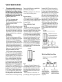
AC Power
Plug the DX7 power cord into any 120 volt, 50 or 60
Hz grounded (3-prong) AC receptacle. It draws 40 watts
maximum. When using the DX7 with an amplifier or
mixer that has an unbalanced input, it is a good idea to
plug both units into the same AC receptacle box or the
same "leg" of the AC service. This will reduce the
chance of hum.
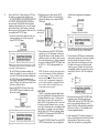
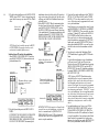
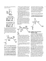
After all connections have been made, turn down the
mixer or amplifier volume as a precaution. Then turn
ON the POWER switch located at the rear of the instrument (on the right side viewed from the keyboard). The
display panel will look like the illustration here for a few
seconds, and will then change to display the mode
which had been engaged before the DX7 was last turned
off.
Installation of Music Rack
The music rack which comes with the DX7 fits into
two sockets on the rear panel (see diagram).
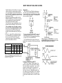
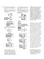
Additional Technical Installation Notes
When connecting the DX7 to an amplifier or mixer, a
maximum unbalanced cable length of 20 feet will
reduce susceptibility to hum, noise, and high frequency
losses; if a longer cable is needed, utilize a "direct box"
which uses a transformer or amplifiers to convert the
output to a balanced line, and then run 2- conductor
shielded cable with XLR-3 or 1/4" Tip/Ring/Sleeve
phone plugs to a balanced input on the mixer or amplifier.
If the cable length is under 20 feet, but the mixer or
amplifier input requires an XLR connector, a direct box
may not be necessary; a simple adaptor cable will often
do the job, so long as complex grounding problems
don't cause excessive hum. To adapt the phone jack
OUTPUT of the DX7 to an XLR input, first check the
manual on the other equipment to see which pin of its
XLR is the "hot" or "signal" pin. In Yamaha equipment,
pin 2 is "hot." Cut the phone plug off one end of a standard guitar-type cable, and connect the center conductor
to XLR's "hot" pin. Then wire the shield to the other two
pins of the XLR; if hum is a problem, cut the shield
connection to pin 1 of the XLR.
Phone-to-XLR adaptor cable.
The nominal output level is -20 dBm (77.5 mV),
although the actual level depends on the voice, the
VOLUME setting, and how many notes are being played
at once. The OUTPUT jack will drive low impedance
(600 ohm) or higher impedance inputs. Maximum output may be considerably higher; since power amplifiers'
nominal input levels are those levels that drive the
amplifier to maximum power, an amplifier rated at 0
dBm or +4 dBm input level may be well matched to
the DX7 output. Mixers with adjustable input sensitivity
may have to be set anywhere from -20 to +4 dBm
nominal, depending on the selected voice, the playing
style, and the DX7 VOLUME setting.
As is the case with any electric or electronic instrument, the AC power receptacle should be checked for
correct voltage and polarity. To find out what to do about
operation with power mains that do not meet these
specifications, contact a Yamaha dealer or authorized
Yamaha DX service center.
13
PLAYING THE FACTORY PRESET VOICES
14
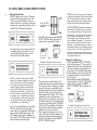
Playing the Internal Voices
1. If the DX7 happens to be on, turn it off. Then turn it
back on while observing the display window. This
will let you see the initial displays we are about to
describe. (In the future, you won't have to turn off the
instrument just to change modes.) When you first turn
on the DX7, the LCD display will briefly show:
NOTE Don't worry if you try to play a chord and the
keyboard acts monophonically rather than polyphonically This simply means the synthesizer is in monophonic mode, and the change to polyphonic mode is
described in the following section of this manual.
Set the VOLUME so
you'll be able to hear
something
3. Enter the PLAY mode by pressing the [MEMORY
SELECT-INTERNAL] button, then select the #1
internal memory by pressing the [1] button.
The number 88 may or may not appear in the LED
voice number display; in any case, after a few seconds, the display will change. However, we don't
know what it will show when it changes.
Press this...
Then...
Press this
The display will change to show the new voice
NOTE: A voice number will be shown in the RED
window, but its number will depend on the voice that
was last selected before the DX7 was turned off; we
have used question marks even though an actual
number will appear. Similarly we placed question
marks in the LCD display because we don't know
what will show in that window... it could be an internal (INT) voice name, a cartridge (CRT) voice name,
or a function; again, it depends on that which was
last used before power was turned off. In order that
you can explore the internal voices and find out for
yourself what they are, do the following:
2. If you are using an amplifier/speaker system with the
DX7, make sure that system is turned on and its
volume controls are set appropriately Whether you're
using an external amplifier/speaker system, or the
DX7 headphone jack and a pair of headphones, be
sure to set the DX7 VOLUME control so there is some
output; mid scale is a good starting point.
There won't be question marks. However, the 32
internal memories may have been loaded with any of
the 4 factory preset banks, something you or another
musician left in memory or something the dealer
placed there during checkout of your instrument prior
to delivery Therefore, we don't know what voice
name will appear. The LCD display "INT 1" is really
redundant here; it tells you that internal voice 1 is
selected, which you can read from the top line of the
LCD window and the red LED voice number display
(Later, when you are editing voices, the "INTERNAL
VOICE" and "INT 1" areas will have different labels,
and the red LED display will become an important
reminder of the voice you have selected.)
4. Play the keyboard, and explore this voice. In fact,
explore all the voices in the internal memories. You
can do this by simply pressing selector buttons [1]
through [32]. You don't have to press [MEMORY
SELECT- INTERNAL] each time.
AVOID FRUSTRATION Although we encourage you to
explore all of the DX7 features on your own, please
try not to jump ahead and press buttons other than
voice selectors 1 to 32 at this time. This can place the
DX7 in a different operating mode so try to resist.
There's nothing wrong with pressing any buttons —
you can't damage the instrument — but if you do go
off on your own, these instructions may no longer
make sense. You may think something is wrong with
the instrument, and to get back to anything recognizeable you will have to start all over again. Bear with
these step by step instructions the first few times, and
then after you really know what the controls do, you
can go ahead and have fun.
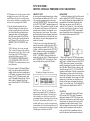
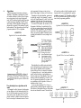
Playing the Cartridge Voices
1. Locate the cartridge labeled "DX7 VOICE ROM" on
the top, with a large numeral "3" on one side of the
cartridge. Slide the switch on that cartridge upward
(away from the connector) to gain access to the 32
voices in bank A. These are labeled "Master Group".
2. Insert the cartridge into the slot near the right side of
the keyboard, orienting it so its switch faces away
from the keyboard.
3. Select the cartridge voice called "BRASSHORNS",
which is in location #A-5 of the DX7 VOICE ROM #3
cartridge. Do this by pressing the [MEMORY
SELECT-CARTRIDGE] button and then the [5]
button.
Press this...
Then press this
The display will change to show the new voice
FUNCTION MODE:
SETTING OVERALL PERFORMANCE PARAMETERS
NOTE Yamaha reserves the right to continue to refine
and update factory preset voices. For this reason,
some ROMs may have this voice in a different location, or may have a different voice altogether. Refer to
the notes which are packaged with the ROMs.
4. Play the keyboard, and explore this voice.
Observe the change in the sound when you
press the key gently and when you hit it hard
(not all voices have this touch sensitivity programmed into them). You'll probably want to
play all the voices in Bank A of this ROM cartridge. You can do this by pressing selector buttons [1] through [32]; you don't have to press
[MEMORY SELECT-CARTRIDGE] each
time.
NOTE At this point, the voice may not sound
"fight" or some of the features of the synthesizer
may not appear to work. This is likely to be due
to the settings of the FUNCTION controls, as
explained in the following section. WHAT
YOU'VE HEARD SO FAR MAYBE DRAMATICALLY CHANGED BY MOVING JUST A FEW
CONTROLS. This is demonstrated in the next section of the manual.
5. If you want to explore the "Keyboard & Plucked
Group" voices that are stored in Bank B of this
cartridge, slide the switch on the cartridge down
to "B" position, and again press the voice selector
buttons [1] to [32]. The same procedures apply
to the "Orchestral & Percussive Group" voices in
Bank A, and the "Complex & Effects Group"
voices in Bank B of the DX7 VOICE ROM #2 cartridge.
IMPORTANT NOTE
In order to provide meaningful examples as we explain
the various buttons and functions on the DX7, we will
refer to specific pre-programmed voices that are provided in the "MASTER GROUP", which is found in bank
A of the DX7 VOICE ROM #3 cartridge that comes with
the instrument. (These procedures are virtually the same
for the internal voices, but since we don't know what
particular voices are loaded in the instrument, we are
using a known set of voices for now. Then our examples should match what your instrument actually does.)
Some control functions have no effect unless the voice
with which they are used is already programmed to be
sensitive to the control.
To play the voice we are using in this portion of the
manual as an example, you will need to set the DX7 to
select the cartridge voice called "ELEC PIANO 1" (Electric Piano 1), which is in location A-8 of the DX7 VOICE
ROM #3 cartridge. From the previous instuctions we'll
assume that cartridge is installed, the [MEMORY
SELECT- CARTRIDGE] button has already been
pressed and the top line of the LCD display already indicates "CARTRIDGE VOICE" (if not, do so now). Therefore you should only have to press the [8] button.
Press this
The display will change to show the voice
NOTE There is no "right way" or "wrong way" to
approach programming of the DX7, although some
methods may be rather inefficient. This chapter is provided to familiarize you with the use of some of the
programming functions. If something isn't perfectly clear
to you at first, don't spend too much time on it; it will
eventually make sense as you play the instrument and
become familiar with its basic features and functions. We
suggest you re-read these instructions after you've gained
a certain degree of confidence with the DX7.
[DATA ENTRY]
A slider and two buttons at the left side of the control
panel are marked [DATA ENTRY]. This group of controls is used for adjusting the settings of almost all the
programmable levels and modes. Moving the slider
down and up may turn one item OFF and ON, set
another for a level of from 0 to 7, and set still another
for a level or rate of from 0 to 99, and so on. For now,
just remember that [DATA ENTRY] is an assignable
group of controls that you use to change whatever you
have selected with other controls on the DX7.
Whatever EDIT mode or FUNCTION mode programming parameter value happens to be displayed may suddenly "jump" to a different value as soon as the [DATA
ENTRY] slide control is operated, or it may change
gradually, depending on the specific value and the position of the slider. Think of the slider as having a scale
(from bottom to top) of 0-3, 0-7, 0-12, 0-99 or OFF-ON,
depending on the function. If the slider is positioned at a
different point on its relative scale than the value displayed in the LCD window, then as soon as the slider is
moved at all, the displayed value will jump to the sliderposition value. In most cases, the two buttons next to
the slider will increment or decrement the displayed
value by 1 unit, with no "jump." The last selected FUNCTION parameter can be adjusted while in the PLAY
mode.
[FUNCTION]
There are 3 main modes of operation: PLAY mode,
EDIT mode and FUNCTION mode. The parameters
which can be adjusted in FUNCTION mode are those
that affect the overall sound, no matter which voice you
select (provided, in some cases, that the voice itself is
programmed to accept the function control). This includes such parameters as the tuning of the keyboard,
whether or not the portamento is active and how it
works, and the effects of the modulation wheel, foot
control, breath control, and the pressure sensitivity of
15
16
the keys (After Touch). Velocity sensitivity is NOT set in
3. While playing a note or chord, move the [DATA
this mode; it is programmed into individual voices.
ENTRY] slider up and down. The pitch will move
ALL THE PERFORMANCE PARAMETERS AFFECTED
with the slider because you have selected MASTER
BY FUNCTION MODE ARE MARKED IN BROWN on
TUNE mode.
the control panel. The Edit Recall and Voice Initialize
functions are also marked in brown, as are the Cartridge
Store/Load and Battery Check functions; even though
these items do not affect the sound of all the voices, they Move slider up to
raise the pitch,
are accessible from FUNCTION mode.
1. In order to examine and/or change the various per-orformance parameters, you first have to press the
Move it down to
brown [FUNCTION] button.
lower the pitch
and forth between polyphonic and monophonic
modes.
Press this
The display will now look like this
Press this
And you will see this
(The message on the second tine of the display could be
one of many It doesn't matter now.)
The red LED diplay will continue to indicate the
selected voice number (#8), and you can still play that
voice, but the LCD display will change to indicate that
the FUNCTION mode has been selected. As with
voice selection, the particular FUNCTION that appears
in the LCD display will be the last one selected, so we
don't know exactly what that is.
2. Press the [MASTER TUNE] button. This sets the
[DATA ENTRY] slider so it can adjust the overall
pitch of the keyboard.
Press this
The display will now look like this
unless MONO mode had last been selected in which
4. The two buttons next to the (DATA ENTRY] slider
normally serve as "fine" adjustments to do the same
thing the slider does as a "coarse" adjusment. In this
particular case, however, the slider by itself is enough
to tune the instrument since it is already programmed
to have fine resolution in MASTER TUNE mode. Tune
the DX7 to A = 440 Hz (slider approximately centered).
NOTE: This function is primarily for tuning the synthesizer to other instruments. By limiting the adjustment
to a narrow range (+ 75 cents), we make it easier to
tune precisely with the slider. However, since each
voice can, itself, be programmed to a unique pitch...
or can be easily transposed (as explained elsewhere),
there is really no limit to the actual pitch you can
create when you press a given key
POLY/MONO
The DX7 is a polyphonic instrument capable of playing 16 notes simultaneously This means that while you
are playing additional notes, up to 16 of them can sustain at one time. As soon as all 16 notes have been
played, the DX7 will drop the first of the 16 notes when
the next one is played. Sometimes, however, you may
wish to have the instrument act as a monophonic (single
note) synthesizer... for example, when you're playing a
lead line. When FUNCTION mode is selected, pressing
the [MONO/POLY] button sets the DATA ENTRY controls so you can make the choice.
1. Press the [POLY/MONO] button. This sets the [DATA
ENTRY] slider and buttons so they can toggle back
case the bottom line will indicate "MONO MODE".
2. If it is not already in MONO mode, set the instrument
to that mode by pressing the [>] button (or by pushing
the slider to the top) and see how the keyboard
reacts. Observe that if you hold down one key then
hit a higher or lower note, you will hear the most
recent key you press. Thereafter, the keyboard is set
correspondingly to high or low note priority until you
release all keys. There is no "fixed" low or high note
priority.
Press
this
And see
this
3. Experiment with moving the [DATA ENTRY] slider
up and down. Notice the display toggle between
"MONO MODE" (slider up) and "POLY MODE" (slider
down). Now try pressing the adjacent [<] and [>]
buttons. Notice they do the same thing as moving the
slider down (<) and up (>). This relationship is true
for most programming functions.
4. Set the instrument to POLY mode by pressing the [<]
button or by pulling the slider to the bottom. See how
the keyboard reacts. Observe that you can play
chords, and if you hold one key pressing another
does not cancel the original note. Leave the instrument set to POLY mode for the time being.
Then use either of these
PITCH BEND RANGE & STEP
The PITCH bend wheel located at the far left side of
the keyboard can be used to "bend" notes or chords,
provided the Pitch Bend Range is set to some non-zero
value. The wheel is spring-loaded to return to center
from either direction.
The maximum pitch bend range is adjustable from 0
(no pitch bend) to a as much as 12 semitones in either
direction (plus or minus an octave). Additionally the
PITCH wheel can be programmed for a smooth, continuous bend, or the change can occur in "steps" of a size
you set (from 0 to 12 semitones). The RANGE adjustment works only when the step size is set to 0; when
discrete steps are selected, the maximum range is 1
octave, with the step size determining the highest and
lowest pitch actually available.
1. Press the [PITCH BEND-STEP] button first. This sets
the [DATA ENTRY] slider and buttons so they can
adjust the size of the steps that will be produced when
you operate the PITCH bend wheel. Try it — move
the [DATA ENTRY] slider (or press the adjacent [<]
and [>] buttons) — then play a note and move the
PITCH wheel.
Since the RANGE function works only when the step
size is zero (continuous glide), move the [DATA
ENTRY] slider, or instead press the adjacent [-1] button as many times as may be necessary to obtain a
step size of zero.
When the DX7 is set for a pitch bend step size of
zero, the display should look like this:
2. Press the [PITCH BEND-RANGE] button and move
the [DATA ENTRY] slider up and down to get different range values displayed in the window. Play a note
or chord and use the PITCH wheel to try each setting.
When you've experimented, leave the system set for a
maximum 12 semitone pitch bend range. (As soon as
you select a [STEP] size other than zero, the
[RANGE] is automatically reset to 12 semitones.)
Then use either of these
When the DX7 is set for a pitch bend range of plus or
minus an octave, the display should look like this:
3. Notice that if you hold a key and hold the PITCH
wheel at a given position, moving the [DATA
ENTRY] slider will not have an effect. You have to
release the wheel first and then play to hear the effect
of the new pitch bend range setting. (This "set-thentest" rather than "set-while-testing" function characterizes many of the DX7 programming controls.)
4. Go back and experiment with different step sizes by
pressing [PITCH BEND-STEP] and moving the
slider and/or pressing the [+1] and [-1] buttons. The
bend was continuous with the step size at 0. A step
size of 1 enables you to hear each semitone as you
move the wheel, and, at the other extreme, a step
size of 12 means you'll hear the note or chord "jump"
a full octave.
Any step size above 0 sets the range to 12, but specific step sizes affects the maximum available range; it
may not always be as much as plus or minus an
octave. For example, if you choose a step size of 5
steps, and move the PITCH wheel slightly you'll get a
jump up or down of 5 semitones. Full deflection of
the wheel from its resting position will cause the pitch
to jump up or down a total of 10 semitones... and
that's it. A range of 6 steps, however, would allow for
an octave of pitch "bend" in 2 increments.
PORTAMENTO FUNCTIONS
NOTES
Several related functions are qrouped under the
FUNCTION heading "PORTAMENTO." The actual
effects obtained will depend upon more than the
PORTAMENTO settings.
What you hear will change when the synthesizer is
set to POLY or MONO mode. We initially explore the
PORTAMENTO and GLISSANDO effects in POLY
mode since that is the mode to which we have.
already set the DX7.
Specific effects also change based on the inherent
sustain programmed into a given voice, and whether
or not you use the SUSTAIN foot pedal. We recommend that you have the FC-4 or FC-5 foot switch
plugged into the rear panel SUSTAIN jack in order to
fully benefit from these instructions. If a footswitch is
not plugged into the PORTAMENTO jack, then the
portamento will be ON.
17
PORTAMENTO & GLISSANDO IN POLY MODE
Sustain: Key Pitch Retain
1. Press [PORTAMENTO TIME] and use the [DATA
ENTRY] controls to set a time of 80, as indicated in
the LCD window. (If the TIME is set at or near zero,
there will be no discernable portamento or glissando
effect, regardless of what you do with the other PORTAMENTO functions. Higher values than 80 are OK,
but will take more of your time than necessary when
exploring these functions.)
Then, if necessary, move the
slider down or press this button so the display indicates
"GLISSANDO=OFF"
The display should look like this
4. Now play several notes, one after the other, whilestepping on the SUSTAIN pedal. Play a bass chord,
then a high note. Observe that the pitch glides from
the previously played note(s) to the next note(s), but
the sustain of the earlier notes remains at their original pitch. Experiment with this effect.
Sustain: Key Pitch Follow
Assuming you have just completed the previous
instructions, the DX7 is in "SUSTAIN: KEY PITCH
RETAIN" mode, with SUSTAIN mode engaged (i.e., GLISSANDO turned off), and a moderate PORTAMENTO
time of 80. Now let's explore "SUSTAIN: KEY PITCH
FOLLOW" mode.
1. Since the DX7 is already in PORTAMENTO mode,
press the [>] DATA ENTRY button or push up the
slider to set the DX7 to SUSTAIN-KEY PITCH FOLLOW mode.
Then adjust this
slider or the adjacent buttons
3. Now press [PORTAMENTO-MODE] to see which of
two possible modes is engaged; the display will indicate either "SUS-KEY P FOLLOW" or "SUS-KEY P
RETAIN." Lets make sure it is set to "SUS-KEY P
RETAIN."
Push up the slider or press this
button so the display indicates
"SUS-KEY P FOLLOW"
Until the display looks like this
The display should look like this
2. Now press [GLISSANDO] to see whether the Glissando is turned on or not; the display will indicate
one of two modes ,"GLISSANDO=ON"or "GLISSANDO = OFF." For now let's make sure it off , which
means the DX7 is in PORTAMENTO rather than
GLISSANDO mode.
Then, if necessary, move the
slider down or press this button so the display indicates
"SUS-KEY P RETAIN"
2. Now play several widely spaced notes or chords, one
after the other, while stepping on the SUSTAIN pedal.
Observe that the pitch again glides from the previously played note(s) to the next note(s), but the sustain of the earlier notes also moves up to the latest
note or chord played (FOLLOWS) instead of RETAINING the original pitch.
Glissando (Key Pitch Retain & Key Pitch Follow)
Glissando is similar to the Portamento effects you just
explored, with this exception; the pitch glide in Portamento is continuous, whereas in Glissando it moves up
or down in 1/2 step increments. Glissando works with
cither the "Follow" or "Retain" functions.
1. Press [PORTAMENTO/GLISSANDO], and then
press the DATA ENTRY [ON] button to place the
instrument in glissando mode.
MODE], you no longer have a choice of "RETAIN" or
"FOLLOW" functions; instead, you can choose between
"FINGERED PORTA" and "FULL TIME PORTA" (where
"PORTA" refers to portamento or glissando); These differences are explained below.
Fingered Portamento (and Glissando)
1. It is OK to leave the Portamento Time at 80, but for
now, let's turn off glissando by pressing [GLISSANDO] and then the DATA ENTRY [OFF] button.
2. Set the DX7 to MONO mode by pressing [POLY/
MONO] and then the DATA ENTRY [>] button.
at the new one, whereas if you continue holding the
first key and release the second key, the pitch glides
back to the original.
5. Now play several notes in succession, releasing one
before playing the nest. Notice that there is no portamento. THIS EXPLAINS "FINGERED PORTA" MODE:
you only get portamento when one key is pressed
while another is still being held down.
6. You can obtain a "Fingered Glissando" effect in much
the same way (with stepped pitch shift instead of a
continuous glide); just press (GLISSANDO) and then
the DATA ENTRY [ON] button.
Full Time Portamento (and Glissando)
1. It is OK to leave the [PORTAMENTO TIME] at 80,
although interesting effects can be obtained at lower
values, too. Leave the keyboard in MONO mode, with
glissando turned off.
2. Select the full time portamento mode by pressing
[PORTAMENTO-MODE] and then the DATA ENTRY
[>] button.
Then move the slider up or
press this button so the display
indicates "GLISSANDO =ON"
3. Select the Fingered Portamento mode by pressing
[PORTAMENTO-MODE] and then the DATA ENTRY
[<] button.
2. Again play several widely spaced notes or chords
while stepping on the SUSTAIN pedal. Observe how
the pitch moves to the most recent note(s) in 1/2 step
increments. The speed can be changed by pressing
[PORTAMENTO-TIME] and adjusting [DATA
ENTRY].
3. The instrument is still in "FOLLOW" mode, so the
glissando effect cancels the sustain of previous notes.
Now try the effect in "RETAIN" mode by pressing
[PORTAMENTO-MODE] and the DATA ENTRY [<]
button.
PORTAMENTO & GLISSANDO IN MONO MODE
When the DX7 is placed in MONO mode rather than
POLY mode, the available portamento/glissando effects
change somewhat. When you press [PORTAMENTO
4. Observe that if you hold down one key, then press a
second key that is a higher or lower note, you will
hear the pitch from the original note move to the new
pitch. If you then release the first key the pitch stays
3. The portamento will work the same as in FINGERED
PORTA mode if you hold a key and then press a
second key However, if you now play several notes in
succession, releasing one before playing the next,
you'll find the portamento remains active. THIS
EXPLAINS "FULL TIME PORTA" MODE; you always
get portamento. even if one key is released before the
next one is pressed down.
NOTE If a foot switch is plugged into the Portmento
jack, it will have no effect in the FINGERED PORTA
mode. In FULL TIME PORTA mode, the foot switch
can be used to turn the effect on and off.
19
20
4. You can obtain a "Full Time Glissando" effect in much
the same way (with stepped pitch shift instead of a
continuous glide); just press [GLISSANDO] and then
the DATA ENTRY [ON] button.
5. Enough work — take a fun break! Now that you've
been exposed to some of the FUNCTION control
features, try using them with other voices. You can
select any voice by pressing either [MEMORY
SELECT-INTERNAL] or [MEMORY SELECTCARTRIDGE] and then any voice selector button
from 1 to 32. Once you've selected a voice, press
[FUNCTION] to experiment with the Master Tuning,
Poly/Mono, Pitch Bend and Portamento functions.
When you've finished experimenting, select the "E.
PIANO 1" voice again.
NOTE The following modes should be reset as indicated so that the rest of the instructions in this section
can be accomplished without confusion from any
portamento, glissando, or pitch bend effects. Press
[FUNCTION], then:
A. Return to polyphonic mode by pressing [POLY/
MONO] and then [<].
B. Turn off glissando mode, if engaged, by pressing
[GLISSANDO] and [OFF].
C. Set the portamento time to zero by pressing [PORTAMENTO TIME] and pulling the [DATA
ENTRY] slider down so the display indicates
"PORTATIME=0".
D. It doesn't make any difference which portamento
mode is set since, with the time at zero, there is no
effect.
MIDI
MIDI is an acronym for Musical Instrument Digital
Interface. The MIDI connectors on the back of the DX7
permit 16 channels of digital information to be shared
with other synthesizers, sequencers, and computer controllers. MIDI permits two or more synthesizers to be
played from one keyboard, as well as remote-controlled
voice selection and even remote-controlled voicing
within the DX series. Voice selector button [8], the
[MIDI] button, actually selects multiple functions in the
FUNCTION mode when it is pressed successive times.
When the display shows "MIDI CH ?" you use the [<]
and [>] to select any of the 16 MIDI channels for receiving information: only Channel 1 is needed to remotely
program or play multiple synthesizers (the other channels are reserved for sequencers, computer interface and
as yet undetermined future uses). Pressing the [MIDI]
button again shows either "SYS INFO AVAIL" or "SYS
INFO UNAVAIL", depending on how you press the
[YES] and [NO] buttons.
"SYS INFO AVAIL" enables you to program other
devices connected by MIDI cable — to send every
parameter for one voice or all 32 internal voices from
the Master to the Slave, and you can also select and play
voices on the Slave(s). To send all 32 voices to another
DX7 (or 20 of them to a DX9), once "SYS INFO AVAIL" is
displayed, press the MIDI button [8] again and, when
the display asks "MIDI TRANSIT?" press the [YES] button (memory protect must be OFF in the other synthesizer). Individual voices or parts of voices can also be
transferred. If you set the instrument so it displays "SYS
INFO UNAVAIL," then you can change programs (select
different voices) and play the Slave from the Master, but
you cannot transfer voice parameters from one instrument to the other.
EDIT RECALL
This function is used as an "emergency backup" to
recall a voice that was "lost" while it was being edited or
created from scratch. Please do not press this button
right now; if you already have, just press [NO] or another FUNCTION button, like [BATT CHECK]. This
button's operation is described in the "FUNCTION
Mode" portion of the "Quick Basic Features" section of
this manual. See page 9.
VOICE INTT (Initialize)
This function is used to create a new voice "from
scratch," and pressing it is the first step of an alternative
method of entering the EDIT mode. Please do not press
this button right now; if you already have, the display
shows "VOICE INIT?"; press [NO] or any other FUNCTION button to cancel the mode. This button's operation
is described in the "FUNCTION mode" portion of the
"Quick Basic Features" section of this manual. See page
9.
CARTRIDGE FORMAT
Voice selector button [11] serves a special purpose in
the FUNCTION mode. Pressing this button selects the
cartridge FORM (format) function. Formatting erases all
the voices in a RAM cartridge. Don't experiment with
this feature unless you're willing to loose the voices on
the RAM. Instead, read the description in the "FUNCTION mode" portion of the "Quick Basic Features" section of this manual. See page 9.
BATTERY CHECK
The battery backup preserves the internal RAM voice
memories when the AC power is turned off. The normal
battery voltage ranges from 2.3 to 3.5 volts. If the battery
voltage is too low, the synthesizer will operate normally
but any voices in the internal memories may be lost or
altered when power is turned off. Therefore, it is advisable to check the battery voltage prior to turning off the
instrument and, if it is low, be sure the internal voices
are saved on a cartridge. (Refer to page 49 for instructions on storing your voices in the RAM cartridges.)
Press the [BATTERY CHECK] button and examine
the voltage. If it is below 2.2 volts, the battery must
be replaced; if it is over 3.6 volts, something may be
wrong with the DX7.
The voltage should be between 2.3 and 3.5
CAUTION The battery is a long-life Lithium
type, and when it is exhausted (below 2.2
volts) it must be replaced by your Yamaha
dealer. Be sure you save any internal voice on
a RAM cartridge before submitting the instrument for a new battery or repair. See page 49
for Cartridge Save and Load descriptions and
directions. Please do not try to change the
battery yourself ; expensive damage that is not
covered by your Warranty may result.
MODULATION WHEEL
FOOT CONTROL
BREATH CONTROL
AFTER TOUCH
When we arrange these four groups of FUNCTION
controls above one another on this page (for the Modulation Wheel, Foot Control, Breath Control and After
Touch), you can see the groups are essentially identical.
There are three main components of a voice to which
LFO modulation can be applied: to the PITCH, to the
AMPLITUDE, or to the EG (envelope generator) BIAS.
(Actually each operator or "sub-component" of a voice
may or may not be internally programmed to be sensitive to these modulation sources.) The fourth button,
RANGE, lets you set the maximum amount of modulation that can be applied to each of the adjacent three
voice components.
The only difference between the four groups of four
FUNCTION controls is the means you use to control the
LFO modulation. It can be introduced:
A) when you move the modulation wheel at the left of
the keyboard,
B) when you tilt an FC-3A foot controller plugged into
the MODULATION jack,
C) when you blow into the BC-1 breath controller
plugged into the BREATH CONT jack, or
D) when you press hard on a key (or keys) to activate
the after touch sensors within the keyboard.
Because the four groups of modulation controls all
operate similarly we will concentrate primarily on just
one modulation source: the MODULATION WHEEL.
2. For now, the object is to turn off all modulation.
Therefore, if the display shows "WHEEL
PITCH = ON", use [DATA ENTRY] to turn if off.
First, make sure all modulation is OFF
NOTE While you may not be using a given source of
modulation, it can still affect the voice if its FUNCTION control parameters are inappropriately set.
SOME SETTINGS COULD RESULT IN LITTLE OR NO
AUDIBLE OUTPUT FROM THE SYNTHESIZER.
Therefore, to simplify the operation as we go through
the following explanations, we first instruct you to turn
off all the modulation sources except the MODULATION WHEEL. Later when you actually play the
instrument, you can turn on the modulation as you
wish.
1. If the instrument is not still in FUNCTION mode
(upper line of the LCD display showing "FUNCTION
CONTROL), press the [FUNCTION] button. Then
press [MODULATION WHEEL-PITCH] and see
whether the modulation is on.
3. Repeat steps 1 and 2 above, but instead of pressing
[MODULATION WHEEL PITCH], press [MODULATION WHEEL- AMPLITUDE] and then [MODULATION WHEEL-EG BIAS]. In each instance, use
[DATA ENTRY] as required to turn OFF the modulation.
(The ??? will either be "OFF" or "ON")
More slider down or press this
button to turn off the modulation
And press this if necessary to
ensure all the modulation
sources are turned off
4. Now repeat steps 1 through 3 above for the Pitch,
Amplitude and EG Bias functions of the FOOT CONTROL, BREATH CONTROL, and AFTER TOUCH
groups; in each case. make sure the LCD display
indicates the function is OFF or else use (DATA ENTRY] to turn it off.
NOTE It is not necessary to press the [RANGE] buttons to set the range for any of these modulation
sources because the range has no effect when the
modulation is turned off.
21
22
5. Play the keyboard and then move the MODULATION
WHEEL toward "MAX". Notice it does not change the
sound; that's because you just turned OFF the Wheel's
effect.
Set this wheel
at maximum
modulation achieved with the wheel will depend not
only on the setting of the wheel itself, but also on the
set Range, and on the Pitch Modulation Sensitivity of
individual voices.
3. Set the MODULATION Wheel at maximum (notch in
the wheel toward the back of the instrument). Then
press [MODULATION WHEEL-RANGE] and use
the [DATA ENTRY] slider to set different values from
0 (no modulation) to 99 (maximum modulation) while
playing the keyboard. IF YOU DON'T HEAR THE
MODULATION, BE SURE YOU'RE HOLDING DOWN
THE KEYS FOR AT LEAST A FEW SECONDS.
NOTE You will now be asked to turn on the MODULATION WHEEL effects and see how they can be
used to alter the sound of different voices.
Selectively turn ON and try the modulation
1. Press [MODULATION WHEEL-PITCH] and then
press the DATA ENTRY [ON] button to activate the
pitch modulation effect.
And set this wheel to take
advantage of the maximum set
modulation
Then move slider up or press
this button to turn on the
modulation
Then move this slider up to
achieve the maximum possible
range of modulation
And see this
2. Play the keyboard and operate the MODULATION
WHEEL.
AT THIS POINT YOU MAY OR MAY NOT HEAR THE
PITCH CHANGE IN A VIBRATO-LIKE FASHION.
THERE REMAIN SEVERAL VARIABLES WHICH WE
HAVE NOT YET DISCUSSED. The amount of pitch
IMPORTANT NOTE At this point it is still possible that
you won't hear any pitch modulation, even when the
wheel is at maximum and the [MODULATION
WHEEL-RANGE] is set to 99. This is because the
voice itself must first have been programmed to be
sensitive to pitch modulation.
4. If you don't hear pitch modulation with the "WHEEL
PITCH = ON", the Wheel at MAX, and the "WHEEL
RANGE = 99", leave these controls set, and try other
voices. Other voices may be programmed to be sensitive to pitch modulation.
From this point, you can access other voices by pressing [MEMORY SELECT-INTERNAL] or [MEMORY
SELECT-CARTRIDGE]. Then press each voice selector button, [1] through [32], and move the MODULATION WHEEL back and forth to test these voices.
When you find a voice that sounds interesting with
the pitch modulation, again press the [FUNCTION]
button and try moving the [DATA ENTRY] slider to
change the modulation RANGE so you can hear how
the wheel works at other than maximum available
range.
5. Now that you've explored the Modulation Wheel
PITCH modulation, try applying AMPLITUDE modulation.
To work without confusing two types of modulation,
you'll want to turn ON only one effect at a time.
Therefore first turn OFF Pitch modulation by pressing
[MODULATION WHEEL-PITCH] and then DATA
ENTRY [OFF]. Then turn ON Amplitude modulation
by pressing [MODULATION WHEEL-AMPLITUDE]
and DATA ENTRY [ON].
NOTE Applying AMPLITUDE modulation makes
individual operators (voice sub-components) louder
and softer, which can affect the volume or the tone or
both, depending on the particular voice's internal
structure. Once again, the voice must be programmed
to be sensitive to the type of modulation. The voice we
have been using as an example, "E.PIANO 1 " is sensitive to pitch modulation, but not to amplitude modulation, so the wheel will not have any effect on the voice
with only amplitude modulation turned on. Try the
other voices to find one which is sensitive to amplitude
modulation; a saxophone voice would be a likely
choice.
6. In a similar fashion to step 5 above, turn OFF the
[MODULATION WHEEL-AMPLITUDE] and turn
ON the [MODULATION WHEEL- EG BIAS]. The
EG bias does not utilize LFO modulation, but instead
it varies the amplitude of any envelopes whose Modulation Sensitivity is programmed to a value greater
than zero. As a result, you can use the MODULATION
Wheel (or any modulation controller such as the
HOW THE DX7 CREATES SOUNDS
Breath Controller or Foot Controller) to turn notes up
and down within the existing envelopes, provided
you are also playing the notes on the keyboard. The
more EG bias, the less amplitude is present when you
play a note; the level increases when you add EG bias
by advancing the Wheel.
7. When you've experimented with [MODULATION
WHEEL-EG BIAS], turn it OFF, and try each of the 3
types of modulation with the other sources (Foot
Control, Breath control and After Touch).
Each of the above sources of modulation can be programmed to function differently, so this is not necessarily a redundant system. For example, you might
use the after touch to add pitch modulation, the modulation wheel to add amplitude modulation, and the
breath controller to alter EG bias (blowing notes,
provided you first hold down the key(s)) for a given
voice.
8. After you've explored all the modulation functions,
we recommend that you go through them and set
them in a way that will be useful as you work
through other sections of this manual. Therefore,
please set the modulation as follows:
CONTROLLER
Operators
The Yamaha DX Series FM digital synthesizers use
pure tones (sine waves) that interact to create all the
overtones needed for any voice. Each sine wave oscillator has its own envelope generator. The combination of
the two is called an "operator."
The primary functional circuit in the DX7 is comprised
of the digital SINE WAVE OSCILLATOR plus a digital
ENVELOPE GENERATOR with multiple inputs and just
one output. This is called an OPERATOR.
If you could look inside an operator (which is just a
digital circuit), you might see a block structure that looks
like this:
FUNCTION
RANGE
PITCH
AMPLITUDE
EG BIAS
MODULATION WHEEL
50
ON
OFF
OFF
FOOT CONTROL
51)
ON
OFF
OFF
BREATH CONTROL
50
ON
OFF
OFF
AFTER TOUCH
50
ON
OFF
OFF
(These settings are not ideal for all voices. If, for instance. you're playing the voice called "SAX - BC1", you
will want to turn ON the Breath Controller EG bias, and
perhaps set Us range to 99.)
Carriers, Modulators and FM
The DX7 has 6 operators. When the output of one
operator is connected to the input of another, modulation occurs. Harmonics are generated — up to a whole
spectrum of frequencies that are the equivalent of a
triangle wave or a sawtooth or a square wave, etc. — all
from a pair of sine waves. Additionally, operator's sine
wave outputs can be mixed together. The two processes,
mixing and modulating (whereby the sine waves interact and produce complex sounds), are called FM synthesis.
When the output of one OPERATOR is "patched" to the
input of another Operator, the result is a complex waveform. This is the essence of FM SYNTHESIS.
24
Algorithms
Different arrangements of operators are known as
"algorithms." An algorithm is something like a "patch"
on a modular synthesizer; it defines the way the operators are interconnected, only instead of using patch
cords, the DX synthesizers digitally switch the operators
to make up the various algorithms. The DX7 lets you
select among 32 different algorithms. Referring to the
diagrams on the top panel of the synthesizer, the small
boxes numbered 1-6 are the operators, and each "map"
pf operators (numbered 1-32) is an algorithm:
ALGORITHM #1
Algorithm 1 has 2 carriers and 4 modulators
stack of
3 modulators
& 1 carrier
A given arrangement of OPERATORS is called an ALGORITHM. The available Algorithms are numbered.
Illustrated here is Algorithm #1, which happens to have
2 parallel STACKS, one with 2 operators, and the other
with 4 operators.
The relationship between algorithms and the
sound
By changing the relative frequencies of each operator,
you can change not only the fundamental pitch of the
note, but also the frequencies present in the note's harmonic structure. Thus, the timbre of the voice can be
precisely controlled. In addition, because each operator
has its own envelope, the harmonic structure of a note
can be programmed to change over time, just as a
plucked string changes its overtones as the note decays.
Depending on the selected algorithm, operators can
be stacked up vertically ("series connected"), arranged
side by side ("parallel connected") or both. In the vertical
arrangement, when the output of one operator is connected to the input of the next, the result is modulation
— the essence of FM synthesis. By convention, we call
the operator at the bottom of a vertical stack the "carrier", and any operators that are above and which feed
its input are known as "modulators." By increasing the
output level of the modulators) going into a given the
carrier, you increase the number of harmonics present,
extending the bandwidth of the voice (making it more
"brilliant").
The bottom operator of a
stack is called a CARRIER.
Any operators which are
connected to the carrier's
inputs are called MODULATORS. YOU CANT HEAR A
MODULATOR DIRECTLY,
but you hear its effect by
listening to the carrier's
altered (modulated) output.
A given operator can be
either a carrier or a modulator: the only difference is
how it is "connected" in a
given algorithm.
Most algorithms have multiple carriers and modulators. In one algorithm a given operator may be a carrier,
while in the next algorithm it may be a modulator —
the only difference is how it is connected. In algorithm
#5, for example, there are 3 vertical stacks connected in
parallel, and each stack has a single modulator connected to a single carrier. Thus algorithm 5 has an equal
number of carriers and modulators (3 of each). In contrast, all 6 operators in algorithm #32 are carriers... there
are no modulators, while in algorithm #16 there are 5
modulators and just 1 carrier.
As you move from algorithm #32 to #1, there is a
greater potential for increased harmonic complexity due
to the structure of the algorithm. However, the algorithm
alone does not determine the sound. The actual nature
of the sound you achieve is highly dependent upon the
frequencies and levels you program into the operators
(modulators and carriers). The 32 algorithms available in
the DX7 were selected because they offer a broad spectrum of useful programming possibilities.
ALGORITHM #5
Algorithm #5 has 3 carriers and 3 modulators
ALGORITHM #I6
1 carrier and 5 modulators.
Algorithm #16 has
ALGORITHM #32
has 6 carriers and no modulators.
Algorithm #32
The results of using different frequency ratios, as well
as different algorithms, are shown graphically in the
accompanying illustration. In the left column, you see
the resulting waveforms created by 1:1,2:1 and 3:1
frequency ratios when a modulator is stacked atop a
carrier — for example, operators 1 and 2 in Algorithm 5
or 16. In the right column you see the resulting waveforms from these same 3 frequency ratios when the two
operators are side-by-side, both serving as carriers so
there is no frequency modulation, but instead there is
additive synthesis.
Still more variations can be achieved by changing the
relative output levels between operators; the greater the
level of the modulator, the more harmonics are present.
Feedback is available in every algorithm
Notice that every algorithm includes one FEEDBACK
path. The feedback is usually "wrapped around" a single
operator, with a few exceptions noted below. The feedback returns a portion of the operators output back to
an additional
input on the same operator (except in
algorithms #4 & #6, where the feedback is returned to
the top modulator on the "stack". In effect, the operator
is modulating itself when feedback is used. While the
feedback paths are part of every algorithm, feedback is
not used in every voice; an editing function permits the
amount of feedback to be set to any of 8 values from
none (0) to a maximum (7).
Often, the only difference between two algorithms is
the location
of the feedback loop. This is true with algorithms #3 and #4, and with algorithms #5 and #6, as
illustrated. If you were to switch between either of the
two algorithms in a pair with the feedback level at 0,
there would be no difference in the sound, whereas
with the feedback at a higher setting, the sound could
differ significantly.
If FEEDBACK is at 0, these two algorithms become
identical
25
26
Envelopes and Envelope Generators
Consider what happens when you play a note. The
volume goes up to some value, then eventually falls to
nothing, with some sort of reasonably well defined pattern that is characteristic of the particular instrument.
For example, a low note on a pipe organ starts slowly
when you press a key due to the time the column of air
takes to build up in the long pipe, and the note takes a
while to die away as the column of air collapses in the
pipe. In contrast, a note played on a wood block starts
quickly as the mallet strikes the block, and dies quickly
as the block stops resonating. The overall pattern of the
volume when you play a note — how loud the note
becomes at any instant, and how long it takes to change
in level — is known as the "volume envelope." Organs
and wood blocks have very different envelopes. With
some unusual "synthesizer" voices, a note may not end
at zero volume, so the next note won't start at zero
volume. In some cases, notes can start at maximum,
then go to zero when you press a key then come back
to maximum level when you release the key; These are
exceptions to the rule, and such notes still have envelopes, even if they are inverted.
Similarly, changes in timbre occur from the onset of a
note to the time it dies away; these changes can also be
defined by an envelope.
In the DX7, each of the 6 operators can be programmed with its own envelope. Generally speaking, if
an operator acts as a carrier in a given algorithm, its
envelope controls the volume of the note. If an algorithm acts as a modulator, its envelope controls the
timbre. (This is a useful conceptual model, although
somewhat of an over simplification.)
Illustrated here is a copy of the envelope diagram near
the upper right corner of the synthesizer front panel. We
have a few additional notes of explanation. The illustration is an aid to visualizing the DX7 envelope settings as
you program or edit a voice. There are actually trillions
of possible envelopes you can define with these EGs.
Each envelope generator in the DX7 permits you to
set 4 different LEVELs and to set 4 specific RATEs at
which the envelope moves from each level to the next.
We use the term "level" rather than "volume" or "tonal
value" because the envelope of the operator you're
adjusting could affect the volume or timbre depending
on the operator's location within the algorithm.
LEVEL 1 (L1) is the level to which the operator begins
moving as soon as you press down the key The operator may reach L1 almost instantaneously, or it may take
over a half a minute to reach LEVEL 1, depending on
the setting of RATE 1 (R1).
NOTE If you are familiar with analog synthesizers that
have Attack-Decay-Sustain-Release envelope generators (ADSR EGs), you may recognize the line defined
by R1 and L1 as the "attack" portion of the envelope.
There are parallels between a conventional ADSR EGs
and the DX7's EGs. However the DX7 envelopes are
much more flexible than ADSR types because the DX7
offers 8 precisely programmable parameters (R1, L1,
R2,L2. R3,L3, R4, L4) instead of 4 (A-D-S-R). I t ' s not
really important for you to understand ADSR envelopes when you're programming the DX7, but if you
already do and are curious about the comparison, see
the envelope discussion in the Advanced Programming Notes section of this manual.
When the operator reaches LEVEL 1, it doesn't stay
there. Instead it immediately begins moving toward the
next level in the envelope, LEVEL 2, and it moves to
LEVEL 2 at RATE 2 (R2).
The change from LEVEL 1 to LEVEL 2 can be an
increase in level, or a decrease in level, depending on
the values you have chosen for these points in the envelope. If, for example, you set LEVEL 1 at the mid point,
and LEVEL 2 at maximum, when you play a note, the
level of the operator will increase to LEVEL 1 and continue increasing to LEVEL 2. If RATE 1 and RATE 2 are
similar, you won't hear two distinct envelope segments.
Instead there will be one smoothly increasing sound.
Suppose, however, that RATE 1 and RATE 2 are quite
different — say RATE 1 is slow and RATE 2 is fast. In
that case, you'll hear a distinct "knee" as the sound
slowly reaches LEVEL 1 and then jumps to LEVEL 2 at
the faster rate.
If LEVEL 2 is lower than LEVEL 1, then the sound
will begin decreasing in level as soon as it reaches
LEVEL 1. falling to LEVEL 2 at RATE 2. If LEVEL 1 and
LEVEL 2 are both set to the same level (other than
zero), RATE 2 has no meaning since the sound is
already at LEVEL 2 the instant it reaches LEVEL 1;
therefore set it to 99. In any case, the sound continues
to move on to LEVEL 3.
The sound moves from LEVEL 2 to LEVEL 3 (which
may be higher, lower or the same as LEVEL 2); the
transition occurs at RATE 3. You may see the similarity
between the second and third segments of the DX7
envelope illustrated (LEVEL 1 to LEVEL 2 and LEVEL 2
to LEVEL 3) and the decay portion of a standard ADSR.
If LEVEL 1 is the highest level in the envelope, LEVEL 2
is lower, and LEVEL 3 is still lower, you have a 2-stage
decay to LEVEL 3. If, on the other hand, LEVEL 3 is set
higher than LEVEL 2, then only the LEVEL 1 to LEVEL
2 segment is a decay, and the LEVEL 2 to LEVEL 3
segment becomes a secondary attack (at RATE 3) to the
higher level.
LEVEL 3 is different than the first two because when
it is reached, the sound does not automatically move
toward the next level. Instead, the sound remains at
LEVEL 3 for as long as you hold down the key.. or if a
sustain pedal is used, for as long as you step on the
pedal. LEVEL 3 thus corresponds to the sustain level in
a conventional ADSR envelope.
When you stop pressing on a key (or lift your foot
from the sustain pedal), the sound immediately begins
moving toward LEVEL 4 at RATE 4. It makes no differ-
PROGRAMMING VOICES: A TUTORIAL
ence whether the envelope had reached LEVEL 3 and
was sustaining, had just reached LEVEL 2, or had not
yet reached LEVEL 1. Whatever the level when you
release the key, the sound immediately moves toward
LEVEL 4 at RATE 4. At the slowest setting for RATE 4,
the sound can linger for so long that you think the note
is stuck (up to 3 minutes). Typically LEVEL 4 is set at
zero (minimum or "off") so that the note eventually turns
off. RATE 4 is analogous to the release time in a standard ADSR.
A major advantage of the DX7 envelope is that each
of the 8 parameters can be set to any of 100 values, providing precision and repeatability The maximum value
of each LEVEL setting is 99, with a minimum value of
zero (off). Similarly, the maximum rate is also 99 (fastest
change in level). Mathematically, this works out to provide something over 1,000,000,000,000,000 different
envelopes (that's right, 15 zeroes!).
NOTE: If you program a carrier envelope so LEVEL 4
is greater than 0, the sound will not die. If you program RATE 4 at or new 0, the sound will seem to last
"forever" Even if you then reset LEVEL 4 to 0 and
RATE 1 to 99, the sound will continue until you play
16 notes, the 16th note cancels the last "lingering" note
that was programmed with the previous settings.
Two basic approaches to creating your
own sounds on the DX7.
There are two basic approaches to programming the
DX7. First, you can run through all the available preset
voices, choose one that is close to the sound you want,
and then edit that voice to create the sound you want.
Second, you can "initialize" the editing buffer of the DX7
and create a voice "from scratch," one that does not rely
at all upon any previously created voice.
The first method, editing a preset voice, is generally a
much more efficient approach, provided the sound you
want is close to something that already exists. (We don't
mean to say that you can't edit an existing voice into
something radically different, but the knowledge and
effort required to do that in a predictable fashion are
formidable.) If you are looking for a unique voice that is
totally unlike any preset, it is probably best to start "from
scratch." The decision about which approach to use will
become easier as you gain experience with the DX7.
Initially we urge you to read this section and follow
instructions carefully as we give you a "guided tour" of
the DX7 and show you how to program a voice "from
scratch." This may seem more difficult, but it is actually
a much better way for you to learn how each of the
editing parameters (functions) really works. In the beginning, it may seem almost overwhelming due to the
unfamiliar terminology and technology. However, as you
become familiar with the instrument and gain a working
knowledge of envelopes, frequency ratios, keyboard
scaling, and so forth, you'll find creating a voice "from
scratch" will become much easier, and editing an existing voice (a preset or one of your own prior creations)
will become a fast, relatively simple process.
Programming a voice "from scratch"
In order to begin programming a voice "from scratch,"
you'll want to have a clear memory location so that
when you've completed working on the voice, you can
save it. Actually, any of the DX7 internal memories can
be used. Nothing is erased while you are creating a
voice, but when you're done and you store the new
voice in one of the memories, whatever voice had been
in that memory will be erased.
CAUTION If you are using the synthesizer after
someone else has been programming voices,
make sure those voices have first been stored
on a RAM cartridge before proceeding. Otherwise you might accidentally "erase" or change
someone else's efforts.
In this section of the manual, we present information
27
in an order which should make it possible for you to
achieve immediate, audible and satisfying results as you
learn to program a voice. To aid in organization of the
information, we have used subheadings that often use
the name of the button, or that describe the use of several buttons which, together, achieve the programming
function being discussed. Many of these subheads
include their own step-by-step instructions. We intentionally restart with Step 1 for each subhead so that you can
later review a single subhead and follow the steps for
programming that particular parameter. Once you have
become familiar with the DX7, there is no "rule" that
you have to follow this order. For now, however, please
read and follow these instructions as presented.
NOTE If you do jump ahead and "get lost" or should
you accidentally program one parameter when you
thought you were working on something else, an
"emergency bail out" is always available: return to the
[VOICE INIT] function presented here at Ihe beginning
of this section. Turning power off and on will NOT
reset your voice.
VOICE INITiaIization
When you want to program a voice "from scratch,"
you do it by initializing a voice. That is, regardless of
which voice you are currently playing, you reset all its
parameters to a starting point which is about the simplest setting that will still produce a sound. This could
take many minutes of button pushing if you had to
manually check each programmable item. To save time,
you can instead use the [VOICE INIT] function.
Although you gain access to "Voice Initialize" from the
FUNCTION mode, the actual voice is not programmed
with the DX7 in FUNCTION mode. As soon as you have
performed the steps below to initialize the voice, the
DX7 is automatically placed in the EDIT mode, and then
the programming begins.
1. To gain access to the "Voice Initialize" function, press
[FUNCTION], and then [VOICE INIT], and answer
the displayed prompts.
28
2. Assuming you want to initialize the voice edit memory (buffer), answer affirmative by pressing [YES]. (If
you changed your mind and don't want to initialize a
voice, press [NO]; the display won't change, but the
voice will not be initialized and you can select any
other function you wish.)
3. The DX7 gives you one last opportunity to avoid
wiping out any voice which you might have been
creating by asking "are you sure you want to initialize
the voice editing memory?" In this case you are sure,
so answer [YES] again. (If you answer [NO], the
display won't change, but the voice will not be initialized and you can select any other function you wish.)
4. The memory number in the LED display will be
whatever had been last selected, but this has no effect
here. Also, the particular operator displayed at the top
right, and the editing parameter displayed on the
bottom line may vary because the DX7 will show the
last used functions or settings. However, it will always
initialize to algorithm 1 with all 6 operators enabled
(turned on).
What is intialization?
What have you just done? You have created a "blank"
in a special memory called the editing buffer. That buffer
memory normally contains the same cartridge or internal memory voice you have selected to PLAY or EDIT
However, once you have "initialized" the editing buffer, it
no longer contains the same information. Instead, it
contains a special "initialized" voice. That voice is nothing more than a sine wave (a pure tone) which is either
on or off.
Remember there are 6 operators. Again, you can
think of these as 6 individually pre-settable sine wave
oscillators each with its own envelope generator that
defines how the operator level changes when you play a
note. In the "initialized" voice, all the operator's EG are
set to produce an envelope with a "square" shape. That
is, when you press a key to play a note, the operator
(the sine wave carrier in this case) is on, and when you
release the key and the operator is immediately off. Try
playing a few notes and hear for yourself.
All operators' output levels are set at 0 except operator
1, which is set at maximum output level (99). In this
case, algorithm 1 is automatically selected by the initialization. This algorithm has 2 carriers and 4 modulators:
operator 1 is a carrier (at the bottom of one stack).
Because operator 1's output level is fully on, you can
hear the sine wave it produces. You hear only a pure
tone because the other operator's levels are at 0, effectively turning them off even though the operators are
"available" because their envelopes are "on". Thus there
is nothing to modulate operator 1, nothing to produce
the harmonics which might create various timbres.
The pitch of each operator is set to frequency ratio
mode at 1.00, so when you play a "C" you hear a corresponding pitch, as explained in one of the following subsections. There is no transposition, keyboard scaling,
detuning of the operators, feedback, etc. In other words,
all "enhancements" are turned off.
How to Interpret the display
Now let's "decode" the display so you can understand
the useful programming information being presented.
Looking at the initial EG settings
Since the envelope is one of the primary factors that
you use to distinguish different sounds, we'll begin programming with the EG (envelope generator) parameters.
1. Press the [EG LEVEL] button, and observe the display You can now examine and/or change one level
at a lime in the envelope for whichever operator is
the "current" operator. DO NOT PRESS ANY OTHER
BUTTONS OR MOVE ANYTHING UNTIL YOU FOLLOW THE NEXT STEP.
This envelope, with all maximum levels (except Level
4) and maximum rates defines a "square" envelope
that turns on to maximum level the instant you press
a key and turns off completely the instant you release
the key If you could see the envelope, it would look
like this:
The "current" operator is that one whose parameters
are being displayed, and which is ready to be reprogrammed. You can see which one is current (OP1
through OP6) by looking at the upper right hand
comer of the LCD display A"?" is illustrated here
because we don't know which operator is current
(that is not reset by the VOICE INIT function).
2. Press [OPERATOR SELECT] as many times as necessary until the upper right corner of the display
shows OP1; if OP is already displayed, you can skip
this step.
This is what the "initialized" envelope would look like if
you could see it. You can hear it, though.
ALG1 1 1 1 1 1 1 OP1
EG LEVELS =99
ALG1 1 1 1 1 1 1 OP1
EG LEVELS =99
NOTE At this point, operator 1, a carrier, is the only
ALG1 1 1 1 1 1 1 OP1
operator contributing to the sound because the output
EG LEVEL 4 = 0
levels of operators 2 through 6 were set at zero when
you initialized the voice. If you were to play the keyboard with the display showing "OP2" or any other 4. Lets look at the 4 envelope rates. Press the [EG
RATE] button, and the display will now show you
operator you would be hearing only operator 1. If you
Rate 1. Press it 3 additional times to see the remainwere to then go ahead and adjust the envelope of an
ing 3 rates. Both EG Rate and EG Level work like
operator other than OP1, you would not hear anythis, in a continuous cycle through the 4 available
thing change because only operator 1 is contributing
points.
to the sound in the DX7's current status. This step,
selecting the "current operator" to be OP1, is necessary
so that you will hear the results of the adjustments we
ask you to make in subsequent steps.
3. Lets just look at the 4 levels for this envelope without
changing them. The display should already show you
that Level 1 is set at 99 (the maximum), as illustrated
above. Press [EG LEVEL] 3 additional times, examining the display each time you press the button. Notice
that Level 1, Level 2, and Level 3 are all set at 99, but
Level 4 is at zero. Normally Level 4 will be set to zero
because if it is at a non-zero point the sound will not
fall to silence when you release the key (A Level 4
value higher than zero is something like latching the
Voltage Controlled Amplifier (VCA) open in a conventional synthesizer.)
And watch
the display
Actually, since L1 and L2 and L3 are the same, R2
and R3 should be set to 99 here to avoid anomalies.
This rate does not affect the "square" envelope;
because the level does not have to change in this part
of the envelope, the rate of change is inconsequential.
R1 (where the sound first builds to L1) and R4 (where
the sound falls to L4) do have an effect, as we are
about to demonstrate.
Experimenting with the EG
Now lets alter the initial envelope to cause the volume
to gradually work up to the maximum (the L1/L2/L3
level), and then gradually reduce to zero (the L4 level)
1. Press EG RATE as many times as required so the
display shows Rate 1 (it should be just once if you
followed the previous instructions to the letter.) Then
move the [DATA ENTRY] slider until the rate
changes from 99 to 25, stopping several times to play
the same note so you can hear the changes that recur
at slower and slower rates.
You may find it easier to press the [<] and/or [>]
buttons to precisely set the rate after using the [DATA
ENTRY] slider to get close to 25. When you're done
experimenting with Rate 1, leave it set at 25.
NOTE The slower the rate, the longer it takes for the
note to build to the maximum level. You can experiment with rates below 25, but you 'll have to wait a
long time for each note to develop. \Vhen Rate 1 is 0
and Level 1 is 99, the sound will take about 40 seconds to reach maximum intensity;
29
30
With all levels at the maximum of 99 (except Level 4,
which is at 0) and with Rate 1 at 25 instead of the 99
to which the other rates are set, the note builds up
slowly when you press a key and turns off the instant
you release the key If you could see the envelope, it
would look something like this:
3. Press a key, wait for the note to build to maximum
volume, release the key and observe how long the
sound lingers. At the slowest rate (0), it takes about 3
minutes for the sound to decrease to complete
silence. (You'll need to push the DX7 [VOLUME]
slider up and/or turn up the volume of the amplifier
in order to hear the last portion of-a long release
time.)
With all maximum levels at 99 (except Level 4), Rate
1 at 25 and Rate 4 at 25, the note builds up slowly
when you press a key and turns off even more slowly
when you release the key This points out an interesting fact about the DX7 envelope rates. Given any
setting (25 in this case), the actual rate of change in
level will be faster when the level is increasing, and
slower when the level is decreasing. In other words,
the actual rate is dependent on the relative levels.
If you could see the envelope, it would look something like this:
2. To change the envelope so the sound gradually falls to
silence when you release the key you must lower
Rate 4. Press [EG RATE] 3 times so that Rate 4
appears in the display and then use [DATA ENTRY]
to change the rate from 99 to 25.
4. To explore the middle of the envelope, press [EG
LEVEL] until Level 3 is displayed, then adjust [DATA
ENTRY] to obtain a Level 3 value of 80. When you
now play a note, observe that it builds to a maximum
value (L1 and L2=99), then instantly drops to a lower
value (L3=80), where it will remain as long as you
hold down the key.
5. The drop to Level 3 from the peak at Level 1 (which
is the same as Level 2 right now), is very abrupt due
to the fast setting of Rate 3. To slow it, press [EG
RATE] as required so you can use [DATA ENTRY] to
adjust Rate 3 to a value of 50.
NOTE If you are familiar with ADSR envelope generators, you'll probably see the similarity between this
envelope and the typical ADSR envelope. However, we
have not yet "used" Level 2, and it can significantly
alter the situation, as you ' l l now learn.
6. Press [EG LEVEL] until LEVEL 2 appears in the
display then adjust [DATA ENTRY] for a value of 45.
Then press [EG RATE] until RATE 2 appears in the
display and adjust [DATA ENTRY] for a value of 50.
Play a note and hold the key down for a full minute,
then release the note.
When you play the note, observe how the sound
builds to a maximum, then falls to almost nothing, then
builds to the intermediate sustain level and stays there
until you release the key after which the sound slowly
fades. This "double" note is made possible by the 4segment envelope which, if it were visible, would look
something like this:
When you play a note, observe how the sound builds
to a maximum, then falls to the sustain level at a
moderate rate and stays there until you release the
key, after which the sound slowly fades. If you could
see this new envelope, it would look something like
this:
*The DX7 envelope rates are internally programmed so that each
segment of the envelope behaves similarly. A level of 99, whether it
is LEVEL I , 2, 3 or 4, is always the same. However, as mentionned
in the preceeding text, when a given rate is used for moving from a
lower to a higher level, that rate will be faster than if the envelope
is moving from a higher to a lower level. This is done because
naturally occuring "attack" times are typically faster than "decay"
or , "release" times. If all rates were scaled identically you might
have to work with the highest numbers for attacks and the lowest
numbers for decay or release. Instead, the DX7's "smart" programming lets you maintain a full 100 step resolution within the range
you need it. This explains why even though Rate 1 and Rate 4 are
both 25 in this case. Rate 1 is faster; it is an upward moving rate.
7. At this point, you're ready to see one more "fine
point" about how the envelope functions. We showed
you how Rate 4 adjusts the release of the note as it
fades from Level 3 (the sustain level) to Level 4 (the
final level) which was set at zero. In fact. Rate 4 sets
the release time from whatever level the envelope has
achieved at the instant you release the key
This may seem a subtle distinction, but you can hear
it by experimenting with the envelope you have just
created.
8. Hold down the key until the note is well info Level 3
(the sustain level). Then release the key, and listen to
the length of time it takes for the sound to decay Play
several more notes, and compare that time to the
rather short time it takes for the sound to fall from the
initial peak at Level 1 to the low point at Level 2. The
difference is because Rate 2 is 50, which is considerably faster than Rate 4, which is 25.
9. Now play a note and let go of the key just as the
sound reaches the first peak at Level 1. Notice how
long it takes for the sound to die away. Even though
Rate 2 and Level 2 are the next segment programmed
in the envelope, the sound is not moving toward
Level 2. Instead, because you released the key the
sound moves from Level 1 directly toward Level 4.
That's why Rate 4 (the slower rate) applies.
Remember, what you hear is coming from the same
EG settings you had established in Step 6 above. If
you could see what happens when you "prematurely"
let go of the key. the envelope might look like this.
Learning to change the operator
FREQUENCY settings
The frequency of the sine wave produced by each
operator can be set so it follows the keyboard. This
characteristic is set with the [OSCILLATOR-MODE/
SYNC] button, and is called "Frequency Ratio" mode
because the frequency produced when you play a key is
not necessarily tuned to the pitch of that key; it can be
multiplied by almost any number you wish by using the
[OSCILLATOR-FREQUENCY COARSE] and [OSCILLATOR-FREQUENCY FINE] adjustments to reprogram the operator. For most voices, the DX7 is set to
this ratio mode. (The Voice Intialize function also-sets
the DX7 to ratio mode.)
The frequency does not have to follow the keyboard,
however. Instead, it can be set to a single frequency that
does not change regardless of which key you play. The
"REFS WHISTL" voice of the "Master Group" on the #3
DX7 VOICE ROM uses this "Fixed Frequency" mode.
While you can adjust the frequency characteristics of
operator 1 (fixed/ratio mode and actual frequency) using
the envelope you just created, we recommend changing
the envelope. The sustain level (Level 3) is now at 80,
and if you hold down a key to experiment with the frequency settings, you will not hear it at full volume.
31
32
Instea d of taking the time to reprogram the envelope ,
we ask you to again use the Voice Initialize feature.. . it
save s time .
1. To gai n acces s to the "Voice Initialize" function , press
[FUNCTION], and then [VOICE INIT], and answer
the displayed prompts .
know , the "initialized" envelop e has all rates a t 99 .
Play a note an d you'll hear the DX7 is back to the
"square " envelope .
3. Now press [OSCILLATOR-FREQUENCY COARSE ]
and operat e the [DATA ENTRY] slide r and/or but ton s while playin g a note . Watch the display a s you
listen to the pitch change.
Then use the slider and/or
these buttons while continuing
to play Middle C
2. Then press [YES] twice to initialize the edit memory
(buffer).
The display shows "EG RATE 2 = 99 " for two rea sons. First , the programming paramete r displayed is
whateve r paramete r you had last adjusted . In this
case , going back to Ste p 6 of the previous instructions ,
you had set Rate 2 a t 50 , so "RAT E 2" is diplayed . The
value , however , is not 50 , bu t is 99 , since, a s you
CAUTION Don't turn up the volume too high
or hold a note very long at the higher frequency ratios or you can easily damage the
high frequency driver (tweeter) in your
speaker system. There's nothing "wrong" with
the synthesizer for "letting you" program such
high frequencies. The very high frequencies
are useful at low levels as part of a voice, or
for modulating with other frequencies in order
to produce lower frequencies that are clearly
audible. Unless you're programming dog whistles or ultrasonic alarm simulations, you
won't ever use a ratio near 31.00 as a fundamental pitch tor a carrier.
NOTE The pitches you hear as you move the [DATA
ENTRY ] slider constitute the Harmonic Series of the
note you are playing. When the diplay indicates "F
COARSE= 1.00" the "1.00" part is the frequency ratio.
The "FCOARSE" part merely tells you that the adjustments you make will be coarse. With the exception of
the "0.50" ratio, all COARSE adjustments are integer
multiples of the fundamental frequency of the note.
That is. "1.00" is the fundamental, "2.00" is 2 times
the fundamental frequency and so forth. If you play a
middle C, "1.00" is 262 Hz, "0.50" is 131 Hz (262 x
0.5), "2.00" is 524 Hz (2 x 262), and "31.00" is 8.122
Hz (31 x 262). The reason we suggest playing Middle
C is that if you play notes at the higher end of the
keyboard, by the time you increase to a ratio of
31.00, you will not be able to hear the pitch because
it will be above the range of human hearing. Speaker
performance is also a factor at these very high frequencies. If you play the A which is normally 440 Hz
when the ratio is "1.00" but change the ratio to
"31.00", the actual frequency is 13,640 Hz. That is
near or beyond the point where many speaker systems "roll off," so even if your ears are good, you may
have difficulty hearing it. Play an A one octave lower
and the frequency is cut in half, so you'll have no
trouble hearing this same 31.00 ratio.
4. Adjust [DATA ENTRY] so the ratio is 1.00 again.
5. Now press [OSCILLATOR-FREQUENC Y FINE]
and operate the [DATA ENTRY] slider and/o r
buttons while playing a not e Watch the display a s
you listen to the pitc h change .
Then slowly move this slider
up and down fully, or use these
buttons while continuing to
play a note
6. Slide [DATA ENTRY] all the way down so the frequency returns to 1.00, and then press [OSCILLATOR-FREQUENCY COARSE] and use DATA
ENTRY [+1] to set the frequency ratio to 2.00.
7. Press [OSCILLATOR-FREQUENCY FINE] again,
and slowly move the (DATA ENTRY] slider all the
way up. The increments you get with the Fine adjustment will depend on the beginning Coarse setting.
The pitch change will seem continuous when the
Fine adjustment is selected and you move the [DATA
ENTRY] slider, rather than discretely stepped, as it
does with the Coarse setting.
If the ratio does not quite reach 3.98 when you push the
slider up, press the increment button [>] once or more.
Notice the maximum increase available with the Fine
frequency adjustment is always a little less than twice
the beginning Coarse frequency The "Fine" control
multilplies the "Coarse" value by up to 1.99. For example, if you start at a ratio of 1.00, the Fine adjustment will go only as high as 1.99 (just under twice
1.00). Start at 2.00, and the Fine adjustment will go
only as high as 3.98. Start at 3.00, and the Fine adjustment will go only as high as 5.94. Start at 31.00,
and Fine will take you up to 61.69. Thus you can use
a combination of Coarse and Fine adjustments to
achieve anywhere from 1/2 the "normal" keyboard
pitch to nearly 62 times that frequency — which is
too high to be audible on all but the lowest notes of
the keyboard.
8. Slowly bring the [DATA ENTRY] slider all the way
down so the pitch returns to a ratio of 2.00. Then
press [OSCILLATOR-FREQUENCY COARSE] and
then the [-1] DATA ENTRY button to reset the ratio to
1.00. (This should now be identical to the "starting"
initialized voice.)
How to create Frequency Modulations
getting acquainted with the OPERATOR
SELECT, OUTPUT LEVEL and ON - OFF edit
featurec
Up to now you have manipulated only OPERATOR 1
which, in ALGORITHM 1, happens to be a carrier. We'll
now leave Operator 1 set at the "square" envelope at a
frequency ratio of 1.00 (as initialized), and begin exploring what happens when Operator 2 is used to modulate Operator 1. For review, we again point out the
Operator On/Off display (which you are about to use)
and illustrate Algorithm 1, but with additional information you may now begin to understand.
NOTE If you 're "lost" or if it has been a while since
you read and followed the instructions in the previous
sections, you can start "from scratch" here by pressing
[FUNCTION], then [VOICE INIT], then answering
[YES] [YES]. The DX7 will now be set as we assume
it is for the following instructions. The display however, may not match: if a different editing parameter is
shown, press [OSCILLATOR-FREQUENCY
COARSE]. Now your diplay should match the following illustration.
Remember the display of 6 1 's tell you the corresponding 6 operators are turned ON at this point in the programming process. The On/Off "switches" are shown in
the following algorithm diagram.
33
34
ALGORITHM #I
These bracketed numbers
show you where the on/off
switching is done in the algorithm. Operators can be disabled (turned Off) using the
[OPERATOR ON/OFF] buttons,
but they remain Off only while
programming. Stored voices
have all operators On. The
reason you have heard only
Operator 1 in the "intialized"
voice even though all Operators are On, is that all output
levels are set to 0, except
Operator 1, whose output level
is at 99.
And watch the current operator change: 1-2-3-4-5-6-1-23 etc.
Leave the display showing OP3.
Since you're only going to be working with operators
1 and 2 at first, this can be annoying if you have to
move from operator 2 to operator 1; it requires that
you cycle through 3, 4, 5 and 6 to get back to 1. In
subsequent steps we show you how to speed the
process of selecting the current operator.
2. Since you will not yet be using operators 3, 4, 5 or 6,
you can turn them OFF by pressing the corresponding [OPERATOR ON/OFF] buttons once. You won't
hear any change in the sound as you play because
those operators are not contributing to the sound
(their output levels are set to zero).
As you can see, the DX7 automatically performs the
OPERATOR SELECT function if you turn OFF an
operator that is set as the current operator.
3. Now press [OPERATOR SELECT] several times and
observe that the display only moves between OP1
and OP2. Leave it set to OP2.
Press each of these buttons once and watch the display
change
The heavy line shows which operators contribute to the
sound: Operator 1 alone in this case
1. Press [OPERATOR SELECT] to change the operator
which is set as the "current" operator. The current
operator is the one whose parameters are displayed,
and which you can program with the DATA ENTRY
controls. Even when several operators are turned ON
and are contributing to the sound, only one at a time
can be adjusted or examined by selecting it as the
current operator.
Each time you press the [OPERATOR SELECT]
button, the current operator increments by one, and
then jumps from 6 to 1 and continues.
As soon as you turn off
OP 3, it cannot be adjusted
So the current OP# automatically goes to the next
operator which is On
When you then turn off
OP4, it cannot be adjusted
So the current OP# goes
to the next operator
which is turned On
4. In the last 3 steps you have pressed a lot of buttons,
but if you bothered to play any notes, you will have
noticed that the sound did not change. In order to
modulate operator 1 and create harmonics, you have
to bring up the output level of operator 2.
Press [OPERATOR-OUTPUT LEVEL] and then
move the [DATA ENTRY] slider up to increase the
level from 0 to 99. Play the note repeatedly as you
increase the settings. You probably won't hear much
until the level is up near 50.
Only the frequency should change in the display
Press this button (Don't
confuse it with [EG
LEVEL], button 22)
Just to review the changes you
have made, notice that the
right hand stack (Operators 3
to 6) are turned off, while
Operator 2's output level is
now increased to 99.
From a minimum of 0.50 to a maximum of 31.00.
Listen to each ratio.
You are changing the entire harmonic structure of t h e
sound by changing the frequency of the modulator.
However, because the modulator output level is at
maximum, the bandwidth of the harmonics is great
(there are a lot of very high frequencies caused by a
lot of modulation). Musically, most of these sounds are
"extreme". You can achieve rather different sounding
results by simply reducing the amount ot modulation,
as demonstrated in the next step.
6. Press [OPERATOR-OUTPUT LEVEL] and thin
This is the
modulator
which creates
the harmonics
Then move this
slider upward slowly
move the [DATA ENTRY] slider down to decrease
And repeatedly play notes until the display shows maximum output level
the level from 99 to 69 Then press [OSCILLATORFREQUENCY COARSE] and again try playing notes
as you adjust the modulator frequency.
Make sure OP2 is current
If you are familiar with analog synthesizers, you may
see a parallel between this sound and that of a sawtooth wave which is going through a filter that has a
lot of resonance. In fact you are frequency modulating
one sine wave with another sine wave; both are set to
the same frequency and the same level. There are no
filters involved.
35
5. Press the [OSCILLATOR-FREQUENCY COARSE]
button and play a note while slowly adjusting [DATA
ENTRY]. In fact play several notes at each frequency
setting, and observe the sound.
And see this
Then move this slider
down slowly or press the
[-1] button
Then move this slider down
and gradually raise it or use
the [-1] and [ +1] buttons while
playing
Until the display shows this output level
36
And again adjust [DATA ENTRY] to hear the results of
different frequency ratios as you play
7. To compare what the sound is like with and without
modulation, you don't have to turn down the output
level of operator 2; you can simply turn it off. Press
[OPERATOR ON/OFF 2] to turn off the modulator,
play a few notes, then press the button again to turn
the modulation back on.
And see the display change from this
Leave Operator 2 set to a frequency ratio of 2.00
The sound you now hear will
be simitar to that of a square
wave in a conventional synthesizer. In this case, it is created
by sine wave modulation of
the carrier by another sine
wave at twice the frequency,
and at a somewhat lower level
than the carrier.
This is the
modulator
which creates
the harmonics
Note that the current operator has
automatically switched to OP1;
remember it can only be set to an
operator that is on.
And see the
display change
to this
Note the current operator stays at
OP1. If you again want to adjust
any parameters for Operator 2, you
will have to press the [OPERATOR
SELECT] button.
8. Now lets see what happens when we leave the modulator (Operator 2) set at a frequency ratio of 2.00, and
change the frequency ratio of the carrier (Operator 1).
Since the current operator automatically switched to
OP1 when you turned off OP 2 above, you can just
press the [OSCILLATOR-FREQUENCY COARSE]
button and play a note while slowly adjusting [DATA
ENTRY].
Then move [DATA ENTRY] while playing a note (or
several)
Listen and watch the display as the ratio changes from
a minimum of 0.50 to a maximum of 31.00
In this case, the effect you get
as you move [DATA ENTRY] is
similar to sweeping a high
pass filter in an analog synthesizer. You're not moving a
filter, of course, but instead
you are controlling the entire
harmonic structure of the note
by changing the carrier frequency relative to a particular
modulator frequency.
9. To compare what the sound is like with and without
the carrier, you don't have to turn down the output
level of operator 1; you can simply turn it off. Press
[OPERATOR ON/OFF 1] to turn off the carrier, and
try to play few notes. (Don't adjust anything else right
now.)
And see the display change from this
NOTHING HAPPENS! NO
SOUND! That's because you
just turned off the carrier, and
you cannot hear a modulator
(Operator 2) directly; you can
only here its effect on a carrier.
With the carrier shut off, there
is no sound.
10. Press [OPERATOR ON/OFF 1] again to turn on
operator 1 and restore the sound.
In the previous Step, the reason we asked you not to
adjust anything is that the current operator changed
to operator 2, and if you were to try pressing edit
buttons and moving the slider you would be reprogramming the modulator without realizing it. You
would not hear what you were doing.
11. Now press [OPERATOR SELECT] to set operator 1
as the current operator (the one to be adjusted), and
adjust its frequency to be 0.50 using the [OSCILLATOR- FREQUENCY COARSE] parameter.
The display should look like this
12. To make the sound more interesting, you'll want to
change the envelopes of the two operators. Beginning with the current operator (1), change its initial
attack rate (Rate 1) and its release rate (Rate 4) using
the [EG RATE] button.
Play a few notes and see how the sound is somewhat more clarinet-like. The square envelope of the
modulator causes the note to become "pure" when
you release the key We'll correct that situation next.
(There is no need to change the EG levels for now.)
Initialized levels
Operator 1 levels
for Operator 1
remain unchanged
EG LEVEL 1 = 99
EG LEVEL 1 = 99
EG LEVEL 2 = 99
EG LEVEL 2 = 99
EG LEVEL 3 = 99
EG LEVEL 3 = 99
EG LEVEL 4= 0
EG LEVEL 4 = 0
13. Now change the envelope of operator 2 the same
way so that the modulator has the same envelope as
the carrier. This is not necessarily desirable in all
voicing. In fact the modulators usually have different
envelopes. However, right now we want to show you
something.
You could press [OPERATOR SELECT], then press
the [EG LEVEL] button and adjust the [DATA ENTRY] slider all over again, but there's an easier way.
Use the [EG COPY] function by holding down the
[STORE] button and then pressing the [EG COPY
2] button. (The 6 Operator ON/OFF buttons are also
EG COPY buttons that you use to designate which
operator will receive the envelope which is being
copied.)
EG COPY copies the entire envelope of the current
operator (the one displayed in the corner of the
window) into whatever other operator or operators
you specify. BE SURE YOU START WITH OP1 in the
upper right corner of the display.
That's it, let go of both buttons. You have just transferred 4 levels and 4 rates from operator 1 to operator 2. Play a few notes. Now the timbre doesn't go
"pure" as soon as you release the key
NOTE There are still many more editing functions to
explore, and we'll use the settings you've just created
as a point of departure for the additional functions. If
you are ready to go on, please continue, ffyou want
to take a break and relax or have some fun with the
37
38
preset voices, you can do so without "losing" this
voice. There are two approaches to this.
(A) You can store this voice in its current state on
a RAM cartridge by following the instructions on
page 49, or...
(B) You can press the [MEMORY SELECT-INTERNAL] or [MEMORY SELECT-CARTRIDGE]
button and then play any preset voices you like.
Later, even if you've turned power off and then on
again, you can return to this voice by doing the
following; press [FUNCTION], the [EDIT RECALL], then [YES] [YES].
Additional editing features: ALGORITHM SELECT, KEYBOARD RATE SCALING, and KEYBOARD LEVEL SCALING
At this point you have programmed Operators 1 and
2, which serve respectively as a carrier and modulator
(as arranged in Algorithm 1), so the frequency modulation creates a woodwind-like character. You have also
modified the initialized "square" envelopes to more
closely resemble a woodwind instrument. We have not
yet created a particularly realistic or even pleasing voice,
but that's not the object for now. We are more concerned
with showing you how the DX7 may be programmed.
Some of the settings we suggest are calculated to most
clearly present concepts to you, not to produce the
"best" voice. This will continue to be the case as we go
on to show you a number of ways to refine the voice.
We ask that you continue to use the settings we recommend. Otherwise, future instructions may not make
any sense — sometimes a slight difference in one setting
will cause another setting to have no effect or far too
much effect. After you've learned how the instrument
works, you'll be able to program voices that are pleasing
to you.
NOTE These instructions assume you have followed
the instructions in the previous section, and that the
DX7 is in the EDIT mode. Before you go on, the display should appear as shown here, and Operators 1
and 2 should be programmed as indicated in the
chart.
If Operators 3 through 6 are ON (display 111111), turn
them off for now (display 110000)
Operator 1 should be
the current operator,
as shown here
This parameter doesn't matter for now because you're
about to select another one anyway
This chart represents what you have programmed so
far:
EDIT mode
PARAMETER
OUTPUT LEVEL
FREQUENCY RATIO
EG RATE 1
EG RATE 2
EG RATE 3
EG RATE 4
EG LEVEL 1
EG LEVEL 2
EG LEVEL 3
EG LEVEL 4
In these fragments of several algorithms, operator 2 is
always modulating operator 1. This is characteristic of
Algorithms 1-19 and 28:
OPERATOR
1
2
99
0.50
43
99
99
50
99
99
99
0
69
2.00
43
99
99
50
99
99
99
0
1. The difference between algorithms is the difference in
the way operators are arranged. Let's try switching the
two operators that are turned on and see what happens to the sound. Press the [ALGORITHM] button
and then press the DATA ENTRY [ +1] button repeatedly to step through algorithms 1 through 32 (or
move the slider up slowly). Play a few notes each
time you press [>] so you can hear how each algorithm affects the sound.
To move from algorithm 1 through
algorithm 32. Be sure to play and
listen to each one.
Surprised? You can get JUST TWO sounds from the 32
algorithms! This is predictable if you look at the algorithm diagrams; in all cases, operator 2 either feeds
into operator 1 (is modulating it) or is adjacent to it (so
the sine waves add instead of causing FM synthesis).
In these fragments of two algorithms, operators 1 and
2 are always adding together. This is characteristic of
algorithms 20-27 and 29-32:
When you later try switching algorithms after adding
FEEDBACK and activating the other 4 operators,
you'll hear much more variation.
2. Pull down the [DATA ENTRY] slider and/or use the
[-1] button until you've selected algorithm 1 again.
Use either
of these
controls
To return to algorithm 1
Alternately play very low and then very high notes
and listen to the envelope attack and release rates.
Then press the [KEYBOARD RATE SCALING]
button, and, for the most noticeable effect, push the
[DATA ENTRY] slider all the way up so you get a
maximum rate scaling value of 7. Then play the same
notes again and listen to the rates. The low notes will
not change much, but the highest notes will have
significantly shorter times. The scaling is not continuously changing with each note, but instead changes
the rates for each group of 3 keys on the keyboard.
When you've tried the maximum, reset the scaling to
a value of 4.
And push up [DATA ENTRY]; leave it set like this
39
KEYBOARD LEVEL SCALING
*With a (-) linear curve set to a depth of 99, the attenua-
tion is 22 dB per octave.
5. If necessary, reset the current operator to operator 1
by pressing (OPERATOR SELECT).
3. It you play the lowest note on the keyboard, then the
highest, you can hear the same attack and release
time. In a natural, acoustic instrument the times
would tend to be faster as you move up the scale.
This is because a vibrating reed or string, or a resonating column of air can be excited more quickly and
will stop moving more rapidly when the string, pipe,
etc. is shorter.
You can achieve this effect by scaling the envelope
rates across the keyboard to any of 8 values (from 0 to
7), as illustrated.
KEYBOARD RATE SCALING
In this case, the rate scaling for the modulator (operator 2) will have little effect, so you don't have to
change it from the "initialized" value of zero.
4. Much like the envelope rates can be varied across the
keyboard, so, too, can the operator output levels. By
using the multiple functions of the 3 KEYBOARD
LEVEL SCALING buttons, you can obtain 99
[DEPTH] settings on either side of a [BREAK
POINT] that you select, and you can also choose any
of 4 [CURVE] settings on each side of that break
point. You can do this for each of the 6 operators.
These selections are diagrammed at the upper right
corner of the synthesizer.
These 3 buttons provide access So all the level scaling
parameters
The DX7 is still in rate scaling mode from the previous step.
6. In order to show you an extreme setting, we will "split
the keyboard" so that this woodwind-like voice component appears on the upper portion of the keyboard
only (When we program operators 3 through 6, we'll
scale them so they work primarily on the lower portion of the keyboard.)
Press [BREAK POINT] and then move the [DATA
ENTRY] controls as required to obtain a break point
ofE4.
40
In this case scaling operator 2 is not necessary so you
can omit the process of setting its break point (which
would be done by pressing [OPERATOR SELECT]
and adjusting the value as desired).
Now play some scales and notice that the sound is
still reasonably uniform across the keyboard. That's
because, while we have selected a break point for the
carrier, we have not yet assigned any depth to the
curves on either side of the break point.
7. Basically there are two types of level scaling curves,
LINEAR and EXPONENTIAL. Linear curves seem to
cause a more rapid boost or cut and are useful for
exaggerated scaling effects, such as keyboard splitting.
Exponential curves are similar to the inherent logarithmic sensitivity of our ears and therefore seem
more "natural". These curves are useful for simulating
the natural changes in level that occur across the
range of an acoustic instrument. Of course, the depth
and break point make a big difference, as does the
operator to which the scaling is applied (modulator or
carrier).
Press [CURVE] and observe the display It will either
show the curve set for the left or the right side of the
break point. If necessary press the button a second
time to ensure that the LEFT curve is displayed. Then
adjust [DATA ENTRY], if necessary, to select a "-LIN"
curve.
Now play some scales and notice how the sound
"goes away" as you move down the keyboard. While
the break point is set at E4, you probably won't hear
the sound getting quieter until you get to C4. By the
time you reach middle C, however, the level is down
about 22 dB. That's about 1/14 as loud. As you move
down the keyboard, the sound disappears. This is an
extreme example of level scaling, and a useful one as
you will hear. Lets leave the lower portion of the
keyboard "rolled off" for now.
9. As you play the highest notes on the keyboard, you
may find the sound to be unnaturally loud. In order
to scale this portion of the sound, you can set the
right curve and depth as follows:
Press the [CURVE] button to see what curve is set for
the right side, and adjust [DATA ENTRY], if necessary to obtain a (-) exponential curve. Then press
[DEPTH] once or twice to see the RIGHT scaling
value and adjust [DATA ENTRY] to get a value of 80.
And adjust the [DATA ENTRY]
controls to see this
8. Set the depth of the left curve (the slope at which the
sound will roll off below the break point). Do so by
pressing [DEPTH] and observing the display which
will either indicate the LEFT or RIGHT depth; if necessary press the button a second time to ensure that
the LEFT depth setting is displayed. Then push up
[DATA ENTRY] to obtain a maximum depth setting
of 99.
Now play up the scale from E4 and hear how you
have removed just a bit of volume from the highest
notes.
NOTE In the examples just given, the keyboard level
scaling may seem to have an effect mostly at the
higher number values, but that's because you were
adjusting a carrier Modulator levels tend to be more
critical, and you'll hear a greater difference in some
voices than others, depending on the algorithm, the
particular location of the modulator within the "stack",
and the actual output level setting of the operator
Remember, also, that if you are "boosting" the level
with a positive (+) linear or exponential curve, you
have to begin with an Operator Output Level that is
less than 99; the lower the Operator Output Level
setting, the more range available for Keyboard Level
Scaling boost.
10. Press [OPERATOR SELECT], then use the KEYBOARD LEVEL SCALING buttons and [DATA ENTRY] to set operator 2 to a [BREAK POINT) of E4
with a "LIN" left [CURVE] and a left [DEPTH] of 99.
LFO Modulation: The relationship
between the "LFO" settings and the
"MOD SENSITIVITY" settings, and how
to program these
The LFO section enables you to set the waveform
[WAVE] and frequency [SPEED] of a sub-audible oscillator. The LFO section has a button [PMD] that permits
you to preset the voice so a portion of that modulation is
applied to change the pitch of the voice (for anything
from vibrato-like effects to exaggerated, continuous pitch
bending). Simultaneously or instead, the same LFO
wave can be assigned to modulate the amplitude (level)
of each operator by using the [AMD] button. Amplitude
modulation can produce tremolo when applied to a
carrier, or "wah-wah" effects when applied to a modulator — among other effects.
A critical concept to grasp is that the modulation you
select with these LFO buttons does not go directly to the
operators. It does not necessarily do what you've set it to
do unless you "open the gates" for the amplitude and/or
pitch modulation output of the LFO to get to the operators.- These "gates" are the Modulation Sensitivity adjust-
41
LFO SECTION BLOCK DIAGRAM
ments. One MODULATION SENSITIVITY control is
provided for PITCH, and another for AMPLITUDE. In
order for you to hear the result of any LFO PMD or
AMD settings, the corresponding [MOD SENSITIVITYPITCH] or [MOD SENSITIVITY-AMPLITUDE] parameter must be greater than zero.
Lets program a small amount of sine wave modulation of the pitch to give the sound some ''character"
1. Press the [WAVE] button. You can now use the
[DATA ENTRY] section to select any of 6 waveforms.
triangle, sawtooth down, sawtooth up, square, sine, or
sample & hold. Set the waveform to SINE.
And adjust the [DATA ENTRY] controls to see this
2. Press [SPEED] and adjust [DATA ENTRY] for a
speed of 50 as a starting point.
And adjust the [DATA ENTRY] controls to sec this
42
3. Press [PMD] (Pitch Modulation Depth), and adjust
[DATA ENTRY] for a value of 50, again, just to begin.
Now play a few notes. You probably won't hear any
change from when you started... even with [PMD] set
at the maximum of 99! That's because while the LFO
is now generating a reasonably fast (SPEED = 50)
waveform (SINE) at a high intensity (DEPTH = 50) for
use by the pitch modulation circuitry the "gate" is still
closed to the frequency shifting inputs of the operators.
And adjust the [DATA ENTRY] controls to see this
4. Press [MOD SENSITIVITY PITCH], and now slowly
raise the PMod Sensitivity value using the [DATA
ENTRY] controls as you play a note. As the sensitivity value ranges from 0 (none or "closed gate") to 7
(maximum), the sound can quickly become weird.
Leave the [MOD SENSITIVITY- PITCH] set at the
lowest value that still gives you a noticeable effect,
which is a value of about 2.
Try all values of [DATA ENTRY] while playing, then set
at 2
5. This is probably giving you far too much pitch modulation, but if you reduce the sensitivity further, there
may not be enough sensitivity for modulation from
other controls (like the after touch, breath controller,
etc.). Therefore, leave the sensitivity set at 2, and
instead lower the Pitch Modulation Depth in the LFO
section. Press [PMD] and then adjust the value to 15.
And adjust the [DATA ENTRY] controls to see this
6. This is an improvement, assuming you're attempting
to program a clarinet-like voice (we are for now), but
the modulation is still much too fast to be natural.
Press [SPEED] and then adjust the LFO speed to a
more natural-sounding frequency... a value of 27
should be about right. Play a few notes and see how
it sounds.
And adjust the [DATA ENTRY] controls to see this
8. There are several additional, related controls we have
not yet explored: [SYNC] and [AMD] in the LFO
section, and [MOD SENSITIVITY-AMPLITUDE].
Lets begin with the [SYNC] function.
[SYNC] lets you use [DATA ENTRY] to turn LFO
Key Synchronization ON or OFF When Sync is ON,
the LFO wave form starts at the beginning of its cycle
each time you play a note. When Sync is OFF the
LFO just keeps running, and each note you play
"catches" the modulating waveform wherever it happens to be in its cycle. This effect is difficult to hear at
the moderate LFO speed and depth you have programmed, so let's temporarily increase the depth and
slow down the speed.
NOTE By now you should know how to set [SPEED],
[DELAY], [PMD] and [MOD SENSITIVITY-PITCH]
so TEMPORARILY change these values. Set a Speed
of 3, a Delay of 0, a Depth of 99 and a Pitch Mod
Sensitivity of 7. This "swooping" may sound strange,
but bear with us.
Temporarily reset these values as shown
7. You have now set the LFO section to automatically
add a small amount of vibrato to the voice, simulating
the natural vibrato in a reed instrument. However, the
effect is there all the time, whereas in a "real" instrument the vibrato might begin a short time after the
note first becomes audible. This delayed onset of LFO
modulation is available in the DX7 by using the LFO
[DELAY] button; press it and set the delay value to 75
with the [DATA ENTRY] controls. Now play, a few
notes and listen after you press a key to the elapsed
time before the vibrato commences. This is probably
a bit too much delay so readjust it to a value of 55 for
now.
And adjust the [DATA ENTRY] controls to see this
9. Press the LFO [SYNC] button and observe the display The Sync should be ON. Play a note and hold
the key down long enough to hear the modulation
"swing" as the LFO wavform repeats. Then play the
same note several times, holding the key down for a
very brief time, and hear how each note starts changing pitch from the same initial frequency.
"open the gate" for each operator that you want the
modulation to affect.
The display should look like this. Play several brief
notes
And adjust the [DATA ENTRY] controls to see this
10. Now use [DATA ENTRY] to turn the sync OFF
Again, play the same brief note several times, and
listen to the pitch each time. You'll hear the initial
pitch of each note change slightly as the randomly
timed notes interact with the regularly oscillating
LFO. With less exaggerated settings, leaving the LFO
Sync OFF will cause minor changes from note to
note that result in a more natural simulation of an
acoustic instrument.
Then adjust [DATA ENTRY] so the display looks like
this, and again play several brief notes
13. Press [MOD SENSITIVITY-AMPLITUDE] and then
press [OPERATOR SELECT] to set Operator 2 as
the current operator. Then use [DATA ENTRY] to
bring up the sensitivity to a maximum of 3. Play a
note, and listen to the timbre change. This modulation will be very pronounced, so you'll probably
want to lower the sensitivity to about 1. The timbre
changes because the LFO is modulating the modulator which produces the harmonics.
And the display should look like this
The two amplitude modulation functions, LFO [AMD]
and [MOD SENSITIVITY-AMPLITUDE], work similarly
to the pitch modulation depth and sensitivity, except that
the amplitude sensitivity can be programmed separately
for each operator. The SAX-BC1 voice in the Master
Group is a good example of the use of LFO amplitude
modulation, where the breath controller can be used to
change the level of several operators.
To see how the amplitude modulation works, lets turn
off the pitch modulation temporarily and turn on the
amplitude modulation.
11. Turn LFO Sync ON again by pressing [SYNC] and
the [ON] button. Then set the pitch modulation
depth at 0 by pressing [PMD] and pulling down the
[DATA ENTRY] slider.
12. Press [AMD] and bring the amplitude modulation
depth up to a high value (from 50 to 99), and play a
note on the upper section of the keyboard. (Remember that the Keyboard Level Scaling has "rolled off"
this sound on the lower part of the keyboard). Notice
there is no amplitude modulation yet. You need to
to select OP2, and adjust [DATA ENTRY] to 3 first, then
to 1
of the carrier through which all the sound in the
stack must travel. Now reduce the sensitivity to 1.
and adjust [DATA ENTRY] to maximum (3) then (1)
15. The amount of amplitude modulation is probably
still much too high, but we may want some amplitude modulation SENSITIVITY for use by an external
modulation source (like the wheel or breath controller). Therefore, leave the sensitivity settings alone.
Instead, press [AMD] and use [DATA ENTRY] to
bring the amplitude modulation depth down to
about 10 (very little depth compared to the maximum of 99).
And adjust the [DATA ENTRY] controls to see this
16. Add some pitch modulation depth (it should be at
zero) to obtain a pleasing frequency variation for
some interest. Press [PMD] and set it to 15. Then
press [DELAY] and set it to 55, press [SYNC] and
turn off the key sync, and press [SPEED] and reset
it to 27.
Now reset all these
parameters for a
more natural
sound
Now lets see what happens when you modulate the
carrier's level.
14. Press [OPERATOR SELECT] as needed to select
operator 1, and then adjust its amplitude sensitivity
to the maximum (3). Play a note in the upper part of
the keyboard, and hear the wide deviations in volume. The wide deviations in volume occur because
the LFO is being applied to change the output level
43
44
Programming the remaining
4 operator*
So far we have used just 2 of the 6 available operators
within the algorithm to create the voice you are hearing.
The remaining 4 operators can be used to add to the
voice and richen it. However, for the purpose of demonstration, we'll show you how to program a completely
different sound with them. Then, by using Keyboard
Level Scaling, you can roll off this second voice in the
upper part of the keyboard so you end up with a split
keyboard.
NOTE In this part of the manual, we'll assume you
are beginning to gain some familiarity with the DX7,
so we won't use quite as many illustrations, nor will
we always instruct you to use [DATA ENTRY] to
alter a value if it should be obvious that that's how the
value is changed. If we say "adjust the frequency ratio
to 3.00" we'll assume that you know how to push the
slider or use the [-1] and [ +1] buttons.
This segment of the voice will become a piano-like
sound. Remember that this is not supposed to be a
"great" sound, just one for learning. In fact, we're eager
for you to experiment with the voice after you create it
so you can make improvements.
1. Press [OSCILLATOR-FREQUENCY COARSE].
Turn ON operators 3, 4, 5 and 6, then turn OFF operators 1 and 2 by pressing the corresponding [OPERATOR ON-OFF] buttons.
The display will show
Note that the current operator automatically changes
to operator 3 (OP3) when you turn off the first two
operators.
2. Change the frequency of operator 3 to a ratio of 2.00.
Then press (OPERATOR SELECT] and adjust the
frequency of each remaining operator as follows:
OPERATOR
FREQUENCY
2.00
3
4
2.00
12.00
5
4.00
6
3. You won't hear anything yet because those operator
output levels are still set at the initialized value (zero).
Reset the levels as indicated below; first press [OPERATOR OUTPUT LEVEL], and adjust the level of the
current operator. Then press [OPERATOR SELECT],
and set the output level for the next operator, and so
forth.
OUTPUT LEVEL
OPERATOR
3
4
5
6
93
93
70
75
Play a few notes and listen to the sound. The "square"
envelopes can be altered, making a major improvement toward obtaining a sound like an electronic
piano.
4. If necessary, press [OPERATQR SELECT] until operator 3 is current. Then press [EG RATE] and adjust
[DATA ENTRY] for each of the 4 rates, setting them
as shown in the following chart. Then press [EG
LEVEL] and set the 4 levels for operator 3, also according to the chart.
OPERATOR 3 EG SETTINGS
RATE1 95
LEVEL 1 99
LEVEL 2 95
RATE 2 20
RATE 3 20
LEVEL 3 0
LEVEL 4 0
RATE 4 50
Play a few notes and observe how the sound now
resembles a hammer strike. This effect occurs because
you have a fast rate to maximum level (R1,L1) for the
"hammer strike", followed by a slow fall to an intermediate decay level (R2.L2), which has the effect of
"widening" the hammer strike and making less of a
"click". There is no sustain level (L3=0) because a
piano string will not sustain indefinitely However, it
will continue vibrating for a long time if you do not
release the key so a very slow rate is set for the fall to
Level 3 (Rate 3=20). If you release the piano key
shortly after striking the note, the sound will fall
rather quickly to zero due to the damper. For this
reason, Rate 4 is set to a moderately fast rate of 50.
Level 4 is, of course, zero so that the sound will eventually fall to silence.
5. You want to have a similar envelope for operator 4,
although a few of the rates can be changed so that the
harmonic structure changes at a different rate than
the overall volume.
You could press [OPERATOR SELECT] to set operator 4 as the current operator, then press [EG RATE]
and [EG LEVEL] 4 times each while using [DATA
ENTRY] to set the desired values. There is an easier
method, as you may recall; use the "EG COPY" function.
To copy the envelope FROM operator 3 to operator 4,
first make sure that operator 3 is still set as the current operator. Then press the [STORE] button and
hold it down while pressing the [4] button. This copies all rates and levels from operator 3 to operator 4.
There is one change to be made for operator 4 in that
Rate 2 must be set at 29 instead of 20, where it had
been for operator 3. Press [OPERATOR SELECT] to
set operator 4 as current. Then press [EG RATE] until
rate 2 appears in the display and adjust it with the
DATA ENTRY [+1] button. The envelopes for operators 3 and 4 now complement one another. The settings are shown below for operator 4:
OPERATOR 4 EG SETTINGS
LEVEL 1 = 99
RATE 1 = 95
LEVEL 2 = 95
RATE 2 = 29
LEVEL 3 = 0
RATE 3 = 20
LEVEL 4 = 0 .
RATE 4 == 50
6. The envelope for operator 6 will be set identically to
that of operator 4. Since OP4 is still set as the current
operator, just press and hold [STORE] and then press
[6] to copy the envelope from OP4 to OP6.
7. Similarly the envelope from operator 3 can be copied
to operator 5. Do so by pressing [OPERATOR SELECT] until OP3 is current. Then press down the
[STORE] button and hold it while pressing [5] to copy
the envelope to OP5.
8. Play a few notes, and observe how the sound has
improved, with much more of an electric piano feel to
it. The "piano" sound now appears across the entire
keyboard. Let's see what happens when the "clarinet"
sound is again introduced.
9. Press the (OPERATOR ON-OFF] buttons [1] and [2]
to turn on the clarinet-like sound. Now play from the
bottom of the keyboard to the top. Notice how there
is only piano sound on the bottom, and how the
clarinet enters in the top half of the keyboard due to
the previous keyboard level scaling of operators 1 and
2.
In this case, we do not want these two segments of
the voice (OP1-OP2 and OP3-OP6) to combine; we
want a "split" keyboard instead. (With another voice,
you might want the two voice segments to play together, complementing one another.) Since we don't
want the piano mixed with the clarinet, let's use the
keyboard level scaling feature to "roll off" the piano
(OP3-OP6).
10. If necesary press [OPERATOR SELECT] to set
operator 3 as current. Then press [BREAK POINT]
and use [DATA ENTRY] to set the break point as
shown below. Next press [OPERATOR SELECT] to
set operator 4 as current, and set its break point as
indicated in the chart. Operators 5 and 6 will not
need any level scaling because their effects will be
adequately contoured by operator 4 (through which
bath must travel).
BREAKPOINT
OPERATOR
3
A2
C3
4
(Doesn't matter)
5
(Doesn't matter)
6
11. Now that the break points are set, you'll need to
establish the curves for each of these operators.
Press [CURVE] and use [DATA ENTRY] to set operator 4 to a negative linear curve on the right side of
the break point. Remember you may have to press
[CURVE] once or twice to see the "R CURVE = ?"
display
12. Set operator 3 as the current operator, and then use
[DATA ENTRY] to set it to a -LIN Right curve.
13. Now set the depth of the right curves for operator 3
by pressing [DEPTH] once, to see the "R DEPTH =
?" display and adjusting [DATA ENTRY] to a value
of 99 (maximum roll off). Press [OPERATOR SELECT] to set operator 4 as current, and set its depth
to 99 also.
You can now play the keyboard and observe how
the sound changes from the piano-like voice on the
bottom to the clarinet-like voice at the top. It's all one
voice, but the component "stacks" of carriers and
modulators are uniquely programmed and scaled to
produce two distinct sounds.
14. To obtain a slightly altered harmonic structure, you
may want to shift the pitch just a little bit for operator 4, the primary modulator in the piano portion of
the voice. You can do this by pressing [DETUNE]
and adjusting [DATA ENTRY] to suit your taste
while playing the piano-like sound on the lower
portion of the keyboard. We recommend starting
with a Detune value of + 3 for OP4.
15. The entire keyboard can be transposed if you like.
Press the [KEY TRANSPOSE] button and then
press the key which you want middle C to become.
Now play and see what happens. If you want to
transpose again, press [KEY TRANSPOSE] again
and press the new "middle C" key This transposes
both portions of the voice.
Suppose, however, that you just want to transpose
the piano portion of the voice. To do this, you do not
use the transpose feature. Instead, you change the
frequency ratios of the operators in that part of the
voice (operators 3, 4, 5 & 6).
16. Press [OPERATOR SELECT] as many times as
needed to set operator 3 as current. Then press
[OSCILLATOR FREQUENCY COARSE] and
you'll see the ratio is now set at 2.00. To transpose
an octave, double this ratio to 4.00. At this point, the
voice will seem to "change" because the modulator
frequencies have not yet been transposed, so the
modulation will, in fact, be producing a different
effect.
17. To "correct" and completely transpose the piano-like
sound, double the frequency ratio of each of operators 4, 5 and 6 by pressing [OPERATOR SELECT]
and adjusting [DATA ENTRY]. Operator 4 increases
from 2.00 to 4.00, operator 5 from 12.00 to 24.00,
and operator 6 from 4.00 to 8.00. Now play across
the keyboard and listen to what has happened... two
lead voices!
Programming velocity sensitivity
The output level of each operator can be programmed
to increase based on how rapidly a key is pressed down.
This is accomplished with the [KEY VELOCITY SENSITIVITY] button. Since the maximum output level of
any operator is always 99, if an operator is already set to
99, it might seem that no further output can be achieved
using the velocity sensitivity. To get around this problem,
the DX7 is designed so that the nominal operator output
level decreases as you program the operator for more
key velocity sensitivity If an operator is programmed for
maximum key velocity sensitivity (7), and you play a
note very slowly, that operator will have a very low
output level; play the same note quickly, and the output
level will increase substantially
To illustrate this feature, lets program the piano-like
portion of the voice to get louder and more brilliant
when you press the keys faster. We'll do something
similar with the clarinet-like portion of the voice. (We'd
say "play harder," which is what we mean, but we don't
want to confuse this parameter with the After Touch
modulation that depends on the pressure you apply alter
the key "bottoms out.")
1. Press [KEY VELOCITY SENSITIVITY] and then
press [OPERATOR SELECT] as required to set operator 1 as the current operator.
and use (DATA ENTRY] to set OP1 like this
2. Then press (OPERATOR SELECT] and use [DATA
ENTRY] to set each of the other operators' for key
velocity sensitivities as shown in the accompanying
chart.
KEY VELOCITY SENSITIVITY
OPERATOR
VALUE
1
3
0
2
2
3
4
7
7
5
7
6
3. The resulting voice will change as you press keys
faster. If you experiment with different velocity sensitivity values, you may find that no combination is
"ideal." It may be necessary to go back and change
the operator output level settings,
Naming and storing the newly
created voice
1. Now that you've created the voice, perhaps you'd like
to give it a name all of your own. Press [VOICE
NAME] and you'll see a blinking cursor (a box) appear at the starting position of the 10 available character spaces for the name. To actually enter a name,
45
46
press and hold down the [CHARACTER] button,
then press individual buttons which correspond to the
letters, numbers, or punctuation you wish to use.
You can determine which buttons produce which
alphanumeric characters by looking at the small dark
brown "reversed" type in the right comer of each
button. If you want to correct a character, continue
holding [CHARACTER] and use the DATA ENTRY
[<] or [>] buttons to move the cursor to the position
you want to change. Then re-enter the new character
(or press [SPACE] to leave a blank space).
2. Now that the voice is reasonably complete, you may
wish to store it on a RAM cartridge, or to store it in an
internal memory If you're going to use the RAM
cartridge, make sure its On-Off slide switch is set to
OFF so that the memory is not protected. You will
then have to turn off the software memory protection
in the DX7 for the cartridge or internal memories by
pressing the corresponding [MEMORY PROTECT]
button and then pressing the [OFF] DATA ENTRY
button. The memory is now ready to accept the voice.
3. Press the [MEMORY SELECT-INTERNAL] or
[MEMORY SELECT- CARTRIDGE] button, depending on where you want to store the voice, then press
and hold down the [STORE] button. While holding
[STORE], press the voice selector button corresponding to the specific location (1-32) in which you want to
place the voice.
That's it. The voice is now stored.
NOTE If you accidentally press a voice selector button
without holding down the [STORE] button, you will
lose the voice you have just created and will. instead,
hear the newly selected internal or cartridge voice.
HAVE NO FEAR, you can recover the "lost" voice by
using the following "EDIT RECALL" procedure:
Edit Recall "Emergency Voice Recovery"
Instructions
a) Press the [FUNCTION] button to place the DX7 in
FUNCTION mode.
b) Press the [EDIT RECALL] button, then press the
[DATA ENTRY] [YES] button to answer the two
prompts "edit recall?" and "are you sure?".
c) You have now recovered the "lost" voice; repeat
step 3 to store the voice.
4. The voice is stored, but it is also still in the edit/play
buffer memory where you can continue to experiment with it. For example, press [EDIT/COMPARE]
to return to the editing mode, and then try adjusting
some parameters. One change we recommend is to
try the different algorithms. Press (ALGORITHM
SELECT] and then change from algorithm #1 to #9.
Notice the improvement in the piano portion of the
voice (at least we think it's an improvement), and the
change in the clarinet side of the voice.
Try all the algorithms to hear the differences they
make in the sound. You may want to experiment with
different EG settings, keyboard rate scaling, and so
forth. If you stumble across something you want to
keep, rename it and store it in another memory location.
5. When you're done with your editing session, press
whichever [MEMORY PROTECT] button you had
originally pressed to turn off the protection (cartridge
or internal), and use the [DATA ENTRY-ON] button
to restore protection so you or someone else cannot
accidentally erase any voices. If the RAM cartridge is
where you saved the voice, also remember to turn on
its hardware memory protect switch once again.
That covers just about all the basic programming
functions of the DX7. If you've mastered this information, you're ready to create any voice you wish. It may
take a bit of practice, but soon the instrument can become an "intuitive" extension of your creative mind.
Hint If you're playing on stage, either presets or voices
you've programmed on RAM, you may want to ID these
voices by applying a length of white masking tape (appropriate width) to the front panel and writing the voice
names next to the voice selector buttons.
Any of the preset voices can be edited to change them
slightly, or totally In fact, the term "primary voice" might
be better than "preset voice," since these voices are not
permanent like the presets of most other synthesizers. In
fact, all DX7 presets are completely programmable. So,
too, are any voices you may have created from scratch
or copied from another DX synthesizer.
A special EDIT mode is provided for editing the
voices, preset or personally programmed. We'll provide
a brief example of editing a preset voice, and you'll see
that the process is almost identical to that of programming from scratch, as previously detailed.
1. Select the Electric Piano 1 voice from the Master
Group of the DX7 voice ROM cartridge. Play the
voice. Lets suppose you want to change the timbre of
the sound so it becomes more penetrating... but not
alter any of the envelopes, fundamental pitches, modulation, or touch sensitivity.
The display should look like this
2. Press the [EDIT/COMPARE] button, and notice that
the display changes to show the last programming
function which had been used. If you've been going
straight through the manual, that function would be
"algorithm select," though it is not important really
3. From the diagram for algorigthm 5 (which the display
tells us is the algorithm of this voice), we see that
operator 2 is the modulator of one stack, and therefore increasing its output level may "brighten" the
voice. We won't know for sure until we try it. Press
[OPERATOR OUTPUT LEVEL] and then press
[OPERATOR SELECT] until operator 2 is set as the
You can see that this is exactly the same way you use
the controls to create a voice "from scratch" using the
current operator.
[VOICE INIT] function. In fact, [VOICE INIT) really
does nothing more than to set all parameters to a
default value, and then places the DX7 in the EDIT
mode. If you want to change any other parameters,
just press the appropriate selector butlon(s) and use
[DATA ENTRY] or any other buttons required to
program the new values. We strongly recommend
that you rename an edited voice by using the [VOICE
NAME] function.
6. If you wish to save the edited voice, you have several choices. If you have edited a preset ROM voice.
you cannot save that voice on a ROM... ROMs are
Read Only Memories. You can, however, save the
edited preset on a RAM (Random Access Memory)
cartridge or in an internal memory within the DX7.
So far, the only clue you have that you are in the Edit
If the "original" voice you edited was selected from
mode is that the LCD display shows editing functions
a RAM or an internal memory, you can over-store
such as "Algorithm Select" and "Output Level." You
the edited voice in the same place, or in a different
are about to see that another aspect of the display can
memory location so you retain the original and
show you whether anything has yet been changed.
edited versions. The method of storing the edited
(So far, you have not actually changed the voice.)
voice is identical to that for storing a voice you
4. Play a few notes, varying the velocity with which you
created "from scratch"; we repeat this below for
press the keys. Then move the [DATA ENTRY]
convenience.
slider to change the output level of operator 2 to 90.
7. You can store the edited voice on a RAM cartridge, or
Notice that the instant you change this parameter, a store it in an internal memory If you're going to use
decimal point appears to the right of the voice numthe RAM cartridge, make sure its On-Off slide switch
ber in the LED display This decimal is your clue that
is set to OFF so that the memory is not protected. You
the voice is no longer the same as the preset. Play a
will then have to turn off the software memory protecfew notes and hear for yourself.
tion in the DX7 for the cartridge or internal memories
by pressing the corresponding [MEMORY PROTECT] button and then pressing the [OFF] DATA
ENTRY button. The memory is now ready to accept
the voice.
8. Press the [MEMORY SELECT-INTERNAL] or
[MEMORY SELECT- CARTRIDGE] button, depending on where you want to store the voice, then press
and hold down the [STORE] button. While holding
Notice this decimal point appears
[STORE], press the voice selector button correspondwhen the output level changes
ing to the specific location (1-32) in which you want to
place the voice. If this is the same location where the
5. If you want to compare the newly edited sound to the
original
voice was located, the edited voice will erase
original sound, you can press the [EDIT/COMPARE]
(and replace) the original. The moment you store the
button once. Notice the decimal point in the LED
voice, the decimal point in the LED voice number
voice number display disappears, and the number
window disappears, and you are out of the EDIT
itself begins to flash. While the number is flashing,
mode.
you can play the original, unedited voice. Press
[EDIT/COMPARE] again and the edited voice reappears, decimal point and all.
47
48
Analyzing and keeping a record
of voices
You can use the EDIT mode to examine all the parameters of each preset... or of any voice. You don't have to
change anything, but the envelope or frequency ratios
or touch sensitivity of a voice may be useful to you in
creating a new voice. In the event a voice is accidentally
erased, the written record can be used to guide you in
reprogramming the voice. We recommend using the
handy form provided on the inside of the back cover of
this manual (unrestricted permission is hereby granted
for you to reproduce as many of the DX7 Voice Data List
forms as you wish). The accompanying form has been
filled out as you might do it to describe the voice created
in the Tutorial section of this manual.
In fact, we recommend using the EDIT mode to analyze and record the parameters of several preset voices
strictly as a learning tool for you. Play the voices, look at
the way the voice is programmed, and try to understand
how the settings affect the sound and touch of the voice.
Here's a hint on how to make useful edits on complex
voices without excessive analysis or trial-and-error.
Select a voice such as a flute, french horn, piano, etc.
Then press [EDIT/COMPARE], and press [OSCILLADX7 VOICE DATA LIST
TOR FREQUENCY-COARSE]. Finally press [OPERATOR SELECT] repeatedly and examine the frequency
ratios for the 6 operators. With most voices, you'll see a
lot of 1.00 and 2.00 ratios, but mixed in with these there
may be one ratio which is unusual, a fine-tuned ratio
like 1.53, or a a very high ratio like 24.00. If you then
adjust the [OUTPUT LEVEL] of that "unusual" operator's frequency ratio, or change its frequency ratio with
coarse or fine control, you can make interesting and
useful changes to the character of the sound.
THE INTERNAL AND CARTRIDGE MEMORIES
We have already described how to play voices that are
stored in the internal memories or cartridge memories.
As part of the tutorial, we have also described how to
store a single voice. The following instructions provide
additional detail on the use of these memories for
storing and rearranging voices. To remain consistent
with the panel labels on the DX7, we use the term
"Store" to describe the process of placing the currently
selected voice (the one which is being played or edited)
into any location (1-32) in the internal or cartridge memories. We use the term "Save" to describe the process of
simultaneously placing all 32 internal memory voices
into the correspondingly numbered cartridge memories.
We use the term "Load" to describe the process of transferring the 32 voices from one bank of a ROM cartridge,
or from a RAM cartridge, into the 32 internal memories.
Memory Protect
When you store a voice (or voices) into an internal or
cartridge memory, whatever voice had been in that
memory location is automatically erased... just like
recording new material over an old tape (although
recording tape is not involved). To help you avoid the
frustration and inconvenience of accidentally erasing
any voices, the DX7 is equipped with several types of
Memory Protection. The [MEMORY PROTECT] buttons provide independent "software" protection for the
internal and cartridge memories. In addition, the RAM
cartridges themselves have "hardware" memory protect
switches. You can always "read" or "load" a voice from a
memory regardless of memory protect status. However,
you cannot store a voice in any internal memory (or
load the RAM voices into the internal memories) unless
the internal memory protect is first disabled (turned
OFF). Similarly, you cannot store a voice in any internal
memory (or save the 32 internal voices to RAM cartridge) unless the cartridge's hardware memory protect
switch is OFF and the DX7's software memory protectcartridge feature is also OFF
The following instructions describe the procedure for
turning the memory protect off; they also instruct you to
turn ON the memory protect as soon as the voice(s)
have been stored. It is a good idea to always turn ON
the memory protect unless you specifically need to store
a voice. This habit may someday avoid accidental erasure of your voices.
Storing individual voices to RAM
cartridge
1. First make sure the Memory Protect switch on the
RAM cartridge is turned OFF (switch positioned away
from the connector).
2. Whether you have been playing an internal voice,
editing a voice, or creating one from scratch in the
VOICE INIT mode, turn off the software memory protect. Press [MEMORY PROTECT-CARTR1DGE],
and the display will indicate "MEMORY PROTECT
CARTRIDGE ???". If "???" is "OFF", the software protection is already off and you can go directly to Step 3.
If the"???" is "ON", then press the [OFF] button.
3. Press the [MEMORY SELECT-CARTRIDGE] button, and then press the [STORE] button and hold it
down while pressing the voice selector button (1-32)
which corresponds to the RAM cartridge memory in
which you wish to store the voice. The LCD display
will briefly indicate "Under Writing", and will then
return to the voice name and number, indicating the
voice has been stored.
NOTE: If you attempt this step with either the software
or hardware cartridge memory protection ON, the display will indicate "MEMORY PROTECTED" as soon
as you press [STORE]. If, when you release
[STORE], the voice name reappears, then the software memory protect is ON; perform Step 2 as above,
then Step 3 again. If, when you release [STORE], the
"MEMORY PROTECTED" message remains displayed, the hardware protect is ON; perform Step 1,
then Step 3 again.
4. Once the voice is stored, press [MEMORY PROTECT- CARTRIDGE] and [YES] to reactivate the
software memory protection, and then reset the
switch on the RAM cartridge to reactivate its hardware
memory protection.
Saving all 32 internal memory voices
to RAM cartridge
1. First make sure the Memory Protect switch on the
cartridge is turned OFF (switch positioned away from
the connector). Then turn off the software memory
protect by pressing [MEMORY PROTECT-CARTRIDGE] followed by [OFF].
2. Press [FUNCTION] to place the DX7 in FUNCTION
mode, and then press [SAVE]. When the display asks
"SAVE MEMORY ALL OF MEMORY?", press [YES]
(unless you change your mind, in which case you
should press [NO] and go on to whatever function
you wish).
3. Because you are about to erase whatever voices are in
the RAM cartridge, the DX7 gives you one more
opportunity to change your mind by asking "SAVE
MEMORY, ARE YOU SURE?" If you indeed want to
save the 32 internal voices in the RAM cartridge,
press [YES] this second time (if not, press [NO]).
4. The display will indicate "SAVE MEMORY, UNDER
WRITING!" for stout 20 seconds as the voices are
being written (saved) onto the cartridge. The d i s p l a y
will then indicated "SAVE MEMORY COMPLETED", at
which point you can select whatever mode y o u w i s h
5. Once the 32 voices are saved, press [MEMORY
PROTECT- CARTRIDGE] and [YES] to reactivate
the software memory protection, and then reset the
switch on the RAM cartridge to reactivate its hardware
memory protection.
Loading all 32 ROM or RAM cartridge
voices to internal memory
1. First turn off the internal memory protect. Press
[MEMORY PROTECT-INTERNAL], and the display will indicate "MEMORY PROTECT INTERNAL
???". If "???" is "OFF", the internal memory protection
is already off and you can go directly to Step 2. If the
"???" is "ON", then press the [OFF] button.
2. Press [FUNCTION] to place the DX7 in FUNCTION
mode, and then press [LOAD]. When the display
asks "LOAD MEMORY ALL OF MEMORY?", press
[YES] (unless you change your mind, in which case
you should press [NO] and go on to whatever function you wish). Because you are about to erase whatever 32 voices are in the internal memory, the DX7
gives you one more opportunity to change your mind
by asking "LOAD MEMORY, ARE YOU SURE?" If you
indeed want to load the 32 RAM voices into the internal memory press [YES] this second time (if not,
press [NO]). After a second or so, the message "LOAD
MEMORY COMPLETED" appears, telling you the
voices are loaded.
3. Once the 32 voices are loaded, press [MEMORY
PROTECT- INTERNAL] and [YES] to reactivate
the internal memory protection.
Transfering a single voice from one
location to another in the RAM
cartridge or internal memory
You may wish to rearrange the voices so they fall in a
particular order as, for example, when you are going to
49
50
play a live performance and you want memories 1-32 to
contain the voices you plan to play in numerical order.
This can be done either in the internal memory or in
the RAM cartridge memory Its best to have at least 1
"blank" or unwanted voice which you can erase when
doing this. If you need all 32 voices, but simply in a different order, make a copy of them (either by saving from
internal to RAM cartridge, or loading from RAM cartridge to internal, as appropriate).
1. Determine whether you want to work with the RAM
cartridge or internal memory and turn off the corresponding sofware memory protection by pressing
[MEMORY PROTECT-INTERNAL] or [MEMORY PROTECT-CARTRIDGE] and then pressing
[OFF]. If you're working with the RAM cartridge,
also be sure its hardware memory protect switch is
OFF.
2. Select a voice you wish to move by pressing [MEMORY SELECT-INTERNAL] or [MEMORY
SELECT-CARTRIDGE], and then the appropriate
voice selector button, from [1] to [32].
3a. Assuming you want to move the voice into a different position within the same memory area (internal
or RAM cartridge) from which you selected it, press
and hold [STORE]. Then press the voice selector
button corresponding to the memory location into
which you wish to move the voice. THIS NEW
LOCATION SHOULD BE BLANK, OR ONE YOU
DONT MIND ERASING, UNLESS YOU HAVE
ALREADY MADE A COPY OF ALL 32 VOICES AS
DESCRIBED PREVIOUSLY.
The voice has now been stored in the new location.
(It still exists in its original location.) Now you can
release the [STORE] button, press the voice selector
of the next voice you want to move, and then press
[STORE] and the voice selector of the memory in
which you wish to store this voice.
3b. If you want to move the voice into the same or a different position within the other memory area (i.e.,
from RAM cartridge memory 6 to internal memory
2), the procedure is similar. You have already pressed
[MEMORY SELECT-CARTRIDGE] and [6] to
select RAM cartridge voice number 6. To assign this
to internal memory 2, press [MEMORY SELECTINTERNAL], then press and hold [STORE] while
you press voice selector [2]. (If you want to move
from an internal location to a RAM cartridge location, substitute the opposite [MEMORY SELECT]
buttons for those in this example.)
To move the next voice from a RAM cartridge to an
internal location, repeat Step 2 and Step 3b.
4. The process can be continued, selecting a voice and
moving it to a new location. As you can see, its like
one of the puzzles where you have 15 numbered
squares and 1 blank space, and you have to rearrange the squares in numerical order — you always
have to use at least one memory location as the
"blank" square so you can shuttle the others around.
That's why we suggest making a copy of all 32 voices
if you plan to move them around within the internal
or cartridge memory. Once you've done most of the
rearranging, you can go to the copied voices and
transfer the "erased" voices back where you want
them using the procedure in Step 3b above.
5. As always, when you have completed the operation,
turn the memory protection back ON.
NOTE: If a "FORMAT CONFLICT "ID CONFLICT
or "READ PROTECT message is displayed during a
STORE or SAVE operation using a RAM cartridge, it
means the cartridge must be formatted. For details,
please refer to the CARTRIDGE FORMATTING section on page 9.
ADVANCED PROGRAMMING NOTES
Playing style and programming of
dynamic control
By now you should be familiar with some of the ways
the DX7's keyboard can be programmed to be touch
responsive. If you have read the programming instructions in this manual and tried to create or edit voices,
you are probably aware of the wide range of sensitivity
settings that are available to you. If not, you can still
experience a good deal of this flexibility by playing the
presets. Excellent preset examples can be found in the
DX7 VOICE ROM #3 Master Group, including Electric
Piano, and Jazz Guitar. Flexibility and variety in programming can be virtues, if used wisely When it comes
to programming the touch response of the instrument,
there is more to consider than "how wide a range can I
obtain?"
Consistency is a primary consideration. We speak of
consistency in terms of your playing style, not the sound
of the voice itself. Use your ears to determine how loud
or bright a sound is created in relation to how forcefully
you play the keyboard. If you strive to program your
voices so the keyboard "plays" similarly the DX7 will
take on a characteristic "feel." If you program each voice
independently you may never become accustomed to
the keyboard because it will behave like many different
instruments. You'll make your job much easier if you
program the DX7 to sound like many different instruments, but to play like one.
When you set out to create a voice that will have
touch sensitivity (Keyboard Velocity Sensitivity and/or
After Touch modulation sensitivity), we recommend that
you work on it while playing and listening at moderate
volume levels. Program the parameters for a mellow,
almost pianissimo sound. Then, when you hit the keys
hard, the voice will have "somewhere to go." Of course,
you have to use some judgement because if you set
things too low to begin with, you provide enough "head
room" in the instrument so that a vigorous "fortissimo"
chord could saturate a tape recording or damage a
speaker system.
The Keyboard Level Scaling is also an important
adjunct to dynamic playing style in that it can be used to
change the output level when you play with the same
touch at different areas of the keyboard. The human ear
tends to be more sensitive to higher frequencies, and
the DX7 normally creates equally intense sound across
its entire keyboard so the net result is that higher notes
can sound too loud or shrill. Therefore, it is often desirable to program a -EXP or -LIN curve on the right side of
the break point, and to use adequate scaling Depth to
"smooth out" the response.
One approach to achieving consistency is to first find
or create a few voices whose keyboard response you
like. Then document the FUNCTION mode modulation
settings as well as the EDIT mode's settings for LFO
(speed, PMD and AMD), Modulation Sensitivity (amplitude and/or pitch), Keyboard Rate Scaling, and Keyboard Velocity Sensitivity settings. Then try to use
settings in this same general range for most of your
voices. Naturally there will be exceptions, but at least
this will give you a framework which suits your own
playing style and taste.
The envelope generator (EG) settings can also have a
signficant effect on the playing response of the keyboard. If the envelope attacks are slow and you're playing a staccatto passage, the notes may not fully develop
— or you may find yourself tending to slow your playing
in order to hear the sound you want. In this case, it
would be worthwhile to reprogram the attack rate, or to
add some Keyboard Rate Scaling if the problem is primarily at the upper end of the keyboard.
All of the preceding suggestions may be completely
inappropriate if you are using the DX7 for creating special effects. Then you may want odd level scaling,
extreme touch sensitivity and so forth.
Additional envelope considerations
Two notes can be sounded from a single keystroke
(for double-tongued trumpet or mandolin like sounds) if
the envelope is programmed as follows:
L1 = 99 (high)
R1 = 99 (fast)
L2 = 20 Qow)
R2 = 35 (slow)
L3 = 95 (high)
R3 = 90 (fast)
L4 = 0 (off)
R4 = 50 (not critical)
The resulting envelope will have a rapid initial attack
upon pressing the key Then the sound begins falling to
Level 2, which will sound like zero even if it is set as
high as 30 or so. The sound then jumps rapidly to Level
3, at which it sustains as long as the key is held down.
However, if you release the key as soon as Level 3 is
attained, the sustain is truncated and you hear a "double
attack" sound. If Level 2 is set at an intermediate point,
say between 40 and 60, the double attack still works.
but the effect is as though Rate 2 and Rate 3 were sped
up. This apparent rate increase occurs because R2
doesn't have to fall to as low a level, and R3 doesn't
have as far to climb, so the time is reduced.
You can simulate an ADSR if you set the envelope as
follows: L1 =99, L2=99, L4=0, and R2=99. With these
settings, then R1 becomes Attack time, R3 is Decay
time, L3 is Sustain level, and R4 is Release time.
To get the "whap" sound of brass, try using [VOICE
INIT] Then, from the initialized voice, leave OP1 as it
is. Change from ALG 1 to ALG 2, change from Feedback=0 to Feedback=7. and then bring up the OP2
output level to 75. This produces the modulation you
need for brass, but not the "whap," Reset OP2 EG Rate 1
from 99 to 70, which causes the modulation to "ramp
up," rapidly increase the harmonics and produce the
characteristic brass attack sound.
Delayed turn-on usiing the envelopes
If you want the Operator attack to begin a while after
you press the key, there are two approaches. One way is
to set the first level (L1) to 99, and to set the attack rate
to a low number (0 to 30). This will result in a gradual
turn-on of the note, with almost no sound at first. If you
want an abrupt (fast) attack, but you don't want it to start
for a while after the key is pressed, you'll need to take a
second approach. Set EG Level 1 to 0; Rl should be set
to 99. Then set Level 2 to 0, and set Rate 2 to achieve
whatever delay time you want. Be sure you press the
key long enough while programming these delayed
turn-on envelopes... it can take over a half a minute
before you hear anything. Set Level 3 to 99 (or some
reasonably high level), and set Rate 3 for whatever
attack time you want on the note. Level 4 should be 0,
and Rate 4 can be set to whatever release rate you
desire.
How to select an algorithm
There are 32 algorithms; all have the same 6 operators and one feedback loop, yet each algorithm is capable of creating sounds that the others cannot. Sometimes
the differences between algorithms are negligible, yet at
times the difference can be dramatic. It may help you to
picture a voice as a the result of two interactive elements, (1) the algorithm, and (2) the frequencies and
relative level of the operators within that algorithm.
An algorithm is nothing more or less than an arrangement of operators. Ultimately, there are just two ways
that the operators can be connected: (1) side by side for
additive synthesis, and (2) one on top of the other for
frequency modulation. "Branching" where one operator
feeds or is fed by two or three other operators, is just a
51
52
variation of the second category. Another variation similar to category (2) is feedback, which creates frequency
modulation through regeneration.
If you were to set the 6 operators to any frequency
ratios you choose, and set their envelopes and output
levels to "typical" values (i.e., values like those found in
several preset voices), you would find that changing the
algorithm would change the sound very markedly
Notice that the 32 algorithms, as illustrated on the DX7
front panel, are sub-divided into 4 major groups (as
shown by the boxes). While we are about to make a
gross generalization, it can be useful in planning an
approach to programming.
The most complex algorithms are at the upper left (1
through 6). These are examples of straight FM synthesis
with two or three "stacks" of operators per algorithm.
Many of the piano voices or orchestra voices are done
with these algorithms because each stack can be programmed as though it were a separate voice within a
voice (hence multiple strings on a piano note, or brass,
bell and flute together).
A different type of complex algorithm appears in the
upper right (7 through 18). These are useful for voices
whose harmonic structure undergoes complex changes,
yet with fewer different "sub voices" within a voice (bass,
harp, and stringed instruments, for example). Of this
cateogry algorithms 7 through 15 include two carriers
each, one of which has multiple stacks of modulators
feeding it through two different carrier inputs (good for
electric pianos as an example). Algorithms 16 through
18 also have branching, but they all have a singe carrier
whose three inputs are fed by different stacks of modulators (good for brass sounds, as an example).
Less complex still are the algorithms pictured at the
lower left (19 through 25). Each includes one modulator
which feeds 2 or more carriers, and the number of carriers form a progression: algorithms 19 and 20 each have
3 carriers, 21 to 23 each have 4 carriers, 25 and 26 each
have 5 carriers. These are useful for sounds with more
discrete attacks and less harmonic complexity — a pipe
organ for example. Algorithms in the lower right (26
through 32) are arranged with a similar progression of 3,
4, 5 and 6 carriers, but these are the least complex
algorithms in terms of the amount of modulation available. They are useful for such sounds as electric organs,
simple wind instruments like a recorder, and so forth.
When you set out to create a given sound, you'll have
to find the group of algorithms that you feel may be able
to do the job; this judgement can be based on looking at
what algorithms the presets use, or by logical reasoning
(after you learn a little more about programming the
DX7.) Within a given group of algorithms, begin with
the least complex algorithm that you feel will do the job
— that is, the algorithm with the highest number. (We
realize that decision, in itself, requires a reasonable
amount of experience and insight... which should come
more quickly if you follow our guidelines.) You may also
find that it is sometimes possible to get precisely the
same results with different algorithms — it depends on
whether you're using feedback, and on the actual output
level settings of each operator. At other times, two or
more algorithms may at first seem to be the same, and
as you refine the voice, you find that only one algorithm
will do the job.
Algorithm Selection Hints:
Two carriers, side by side, can be functionally equivalent to having two distinct sound sources that are
simply added together. You can also program the two
carriers with nearly the same parameters for a "richer"
or "thicker" texture.
Regardless of the algorithm you select, use the fewest
number of operators you can when you begin to program. Turn off the others while programming by using
the [OPERATOR ON-OFF] buttons; if you want them
to remain off alter the voice is stored, turn their
[OPERATOR OUTPUT LEVEL] to zero.
Learn to program by studying how
acoustic Instruments work
It is important to consider how an acoustic instrument
creates sound, and to think about the relationship
between particular "patches" on the DX to the method of
sound generation in the acoustic instrument. For example, if you are trying to duplicate the sound of a piano,
you would observe that many piano keys cause a hammer to strike two or three strings. Therefore, you might
want to use an algorithm with two or three carrier/
modulator stacks. Each stack can then be programmed
to duplicate the sound of a different string, emulating the
2 or 3 strings struck by the hammer. There are other
considerations, such as the sound of the hammer itself.
You may program one stack to synthesize the sound of
the felt striking the string(s), and then use the remaining
stack(s) to create the string sound. The shifting harmonic
structure of the acoustic piano note can be simulated by
using different envelopes for each modulator. The inharmonicity (where harmonics are not in tune with the
fundamental) can be simulated by using the [DETUNE]
function, and thereby changing the modulator frequencies to be slightly "off" from the perfect integer ratios.
(Even though the frequency might still indicate something like "2.00", Detune causes it to be more like "2.001
or 1.998".)
If you're working on a bowed or plucked string sound,
you can probably visualize the string being stretched
initially then, as the vibration settles down, the note gets
quieter. The initial stretch not only leads to a louder
sound, it also raises the pitch, which then falls steadily
toward the "normal" pitch of the note as the amplitude
also falls. This effect can be simulated by using the Pitch
Envelope. Set it for a slight increase in pitch initially (L1
slightly higher than 50), and then set the pitch of the
rest of the voice to be "normal" (L2, L3 and L4 at 50). R1
should be at 99 so that the pitch initially starts at the
higher frequency and then R2 can be set to a moderate
rate so the pitch falls to normal at a rate resembling that
of the plucked or bowed string. LFO pitch modulation
can simulate vibrato, and so forth.
By following this logical approach, you should be able
to figure out how to program more complex sounds with
less guessing... or at least with more directed guessing.
This is not to say that other methods are invalid or will
not work — there are many ways to obtain a pleasing
sound. Some piano voices, for example, can be achieved
using Algorithm 19, which has just one carrier. The
multiple stacks of modulators which all affect that carrier
can be programmed to achieve the hammer strike and
string sounds.
There is more than 1 way to create
a pitch
There are many ways to achieve a given pitch within
a particular voice. At first, it may seem that the carrier
frequency determines the fundamental pitch of the
voice, and the modulator(s) affect primarily the harmonics or overtones. However, you will find this is not
necessarily the case. For example, changing the carrier
to a frequency ratio of 6.00 and the first modulator
above it to a ratio of 2.00 can produce tones that have a
fundamental pitch which is considerably lower than the
6.00 ratio would suggest. This is due to the strength of
the sum and difference products of modulation — the
so-called "sub harmonics" which are produced. When
you are trying to get a particular sound, take the time to
experiment with many different frequency ratios, not
just the "obvious" choice. Moreover, be sure to try differ-
ent modulator output levels for each combination of
frequencies, since this can make a world of difference in
the sound.
Ensemble voices may differ from
solo voices
When a musician plays an instrument as part of an
ensemble, whether 2 or 70 people are playing, the
sound of his instrument will interact with the other
sounds. There is a certain balance to be struck between
blending with the other instruments, yet retaining a
distinct identity. The need to retain an identity in the
midst of this complex group texture (even if the "group"
is nothing more than tape recorded Overdubs of the
same DX synthesizer) calls for a more "penetrating"
sound, sometimes one with more exaggerated LFO
modulation or a slightly "edgy" harmonic structure. The
same voice might sound too harsh or exaggerated in a
solo performance. When you are programming a voice,
be sure to evaluate it in the musical context where it will
be used. You may want to program and store two variations of the same voice, one for ensemble and one for
solo use. Some of the preset voices include the term
"ensemble" (ENS) in their title; these voices often work
better in an ensemble than as solo voices.
Breath controller applications
and hints
There are certain types of instruments that are difficult
to phrase or articulate with a keyboard, such as brass or
vocal sounds. The BC-1 breath controller may be used
to phrase and shape the envelope or to add modulation
of pitch and amplitude. The BC-1 is sensitive to pressure; the harder you blow into it, the more voltage it
applies to the synthesizer's Breath Controller input. This
voltage can be programmed to affect different aspects of
the voice. The changes it brings about can be made
very quickly — a great asset when performing. However,
in order to use the breath controller, various parameters
must be programmed into both the voice and the
FUNCTION mode of the instrument.
To explore the use of the breath controller, select a
voice which includes amplitude modulation sensitivity
such as the "SAX-BC1" voice from the Master Group.
Then plug in the Yamaha BC-1 breath controller.
Amplitude modulation with the BC-1
Press the [FUNCTION] button and then press
[BREATH CONTROL-RANGE] and set the range to
50. Then press [BREATH CONTROLLER-AMPLITUDE] and turn it ON. Within the voice itself, the
amplitude modulation sensitivity of one or more operators must be set to 1 or higher. In this case, the BC-1
may alter the volume, the timbre, or both depending on
whether the AM sensitivity is turned up on the carriers)
or modulator(s). Play the instrument and blow into the
BC-1 to hear what happens.
NOTE If you have to blow too hard while playing a
voice which is known to be modulation sensitive, you
may want to adjust the sensitivity of the BC-1 itself.
Use a small slot-blade screwdriver to turn the recessed
screw on the bottom of the unit. You can also cover up
the small vent hole in the BC-1 with your finger or
adhesive tape; this will increase the effectiveness of
your breath, but will restrict the playing style somewhat (it also quiets the BC-1).
EG BIAS modulation with the BC-1
When you turn up the EG bias (99 max), the actual
level of each operator whose AM sensitivity is above 0
will go down. With a maximum AM sensitivity of 3, and
EG BIAS of 99, the operator level will be zero. Then,
when you blow hard into the BC-1, the level comes
back up to the maximum level permitted by the envelope at any given instant; you must have played the
note first on the keyboard so that the EG bias is bringing
up the level within the programmed envelope. The rates
of the envelope remain unchanged, but the sound will
disappear instantly if the BC-1 is not blown.
For creating a voice like the "SAX - BC1" preset,
where you may want all the sound controlled by the BC1, you might set all the operators' amplitude modulation
sensitivities to 3, and the BC range to 99. In something
like the E.P-BRS BC (Electric piano-Brass Breath Controlled) voice in the complex & effects group, the piano
portion of the voice is not affected by the breath controller because these operators' AM sensitivities are at 0, but
the operators in the brass portion of the voice have their
AM sensitivities set at 3; the [BREATH CONTROLLER-RANGE] should be 99 for this voice.
With the "Sax - BC1" voice you may want to use the
BC-1 for phrasing (EG bias), use after touch for vibrato
(Pitch), and use the foot control for overall volume. The
Modulation Wheel can be used to apply LFO amplitude
modulation.
Pitch modulation with the BC-1
Turn on the pitch modulation (we assume the range is
still set between 50 and 99). You will also need to set the
pitch modulation sensitivity within the voice itself to a
value of 1 or higher (check this in EDIT mode, and
change if necessary). Hold down a key, and blow on the
breath controller. You should hear a vibrato effect — the
speed has nothing to do with how you blow since it is
set by the LFO speed which is programmed into the
voice — your breath affects the vibrato depth.
Breath controller techniques
You can use the breath controller several ways. Take it
into your mouth and grip it with your teeth. Touch a key
on the keyboard, and begin to blow gently If the voice is
set up for breath controller EG bias, the note will begin
to sound, and will become louder the harder you blow
If the voice is set up for pitch modulation, the vibrato
will increase as you blow harder. If the voice is set up for
amplitude modulation, the tremolo and/or wah-wah will
increase as you blow harder.
The EG bias is perhaps the most interesting modulation for the breath controller. When you blow normally.
the notes start softly By tongueing the note (forming the
breath with a "T" sound), you can get a harder edge. By
finishing the blowing with a "T" sound, you can get the
note to end abruptly Of course, you have to coordinate
the blowing with the playing of the notes on the keyboard. Given maximum EG bias modulation and maximum amplitude modulation sensitivity within the voice,
there will be no sound when you play a key; the sound
will come only when you hold the key and then blow
into the BC-1. It may take some practice to achieve the
proper coordination.
You can achieve a "growling" effect by humming into
the BC-1 while you are blowing. This can create an
occasionally useful "gritty" sound for playing saxophone.
for instance, or an overdriven lead guitar. You'll want to
experiment with combinations of humming, tongueing
by means of "T-ing", "D-ing" or "F-ing", and so forth. An
"F" or "CH" sound may be better for whistles, while a
"too-kah" sound may do the job for a birdsong. The
possibilities are particularly exciting when you blend the
breath controller effect with the pitch bend wheel or
other modulation sources.
Special effects from [DATA ENTRY] while
in PLAY mode
The DX7 [DATA ENTRY] section continues to be
53
54
"live" after you exit the FUNCTION mode by pressing
one of the [MEMORY SELECT] buttons (internal or
cartridge). The [DATA ENTRY] controls only change
the last used parameter prior to pressing the [MEMORY SELECT] button. This feature can be useful as an
additional live performance control. For example, you
might go into the EDIT mode and select [LFO
SPEED]. Then go back to the PLAY mode and you can
play any voice you like and change its LFO speed by
moving the [DATA ENTRY] controls. Similarly, you can
go into FUNCTION mode and adjust [MASTER
TUNE], then go back into PLAY mode and use [DATA
ENTRY] to tune a voice. One application of this characteristic is to achieve simulated "doppler shift" with the
train bell or whisltle (Doppler effect is the increase in
pitch that occurs as two objects move closer togther at a
rapid rate, and the decrease in pitch as they move
apart).
One of the most important parameters to access during performance is the POLY/MONO mode selection.
You can exit FUNCTION mode after first pressing
[POLY/MONO], and then toggle between these modes
while playing various voices.
The ability to change the last selected FUNCTION
parameter is particularly useful for changing the
portamento characteristics. For example, you can enter
FUNCTION mode and adjust the [PORTAMENTO
TIME], then play a voice and alter that time as you play.
A very useful "trick" relies upon the difference in portamento that occurs between polyphonic and mono
modes. As explained here, you can use [DATA
ENTRY] to switch between fingered portamento with a
mono keyboard (useful for a Fretless Bass voice), and no
portamento with a polyphonic voice (Electric Piano, for
example).
1. Wire a standard phone jack so its tip is shorted out to
its sleeeve (jumper from tip to sleeve). Insert this plug
in the Portamento Foot Switch jack on the back of the
DX7. It has the same effect as though you plugged in
a foot switch but did not step on it.
2. Enter FUNCTION mode. press [POLY/MONO], and
set the instrument for MONO operation.
3 Press [PORTAMENTO MODE] and select "FINGERED PORTA". You'll notice that fingered portamento is not sensitive to the portamento foot switch,
so it will work even though the shorted jack is
present.
4. Press [POLY/MONO] again before leaving FUNCTION mode so that the [DATA ENTRY] slider or
[ON] and [OFF] buttons will toggle the keyboard
between polyphonic and mono operation.
5. Press [MEMORY SELECT] (internal or cartridge) to
enter the PLAY mode.
When you select a voice like the Fretless Bass, push
up [DATA ENTRY] or press [>] to set the DX7 to
MONO mode. You can now use fingered portamento
(holding one key while pressing and releasing
another) to achieve a pitch bending glide to the next
note, or play notes sequentially to avoid portamento.
If you select another voice, such as Electric Piano, pull
down [DATA ENTRY] or press [<] to return to polyphonic operation; since the portamento jack is
shorted, there will be no portamento on that voice. If
you want, you can use a foot switch in the Portamento jack, in which case the portamento would be
active in POLY mode when you step on the pedal.
If you don't want to accidentally have a parameter
change whenever you're in PLAY mode, select a noncritical parameter before you exit the FUNCTION
mode. From FUNCTION mode, for example, you
might press [BATT CHECK] before going into PLAY
mode. This will avoid accidental, unexplained
changes while you are playing.
Reference Sources on FM Synthesis
FM digital synthesis, of the type used in the DX synthesizers, was pioneered by Dr. John M. Chowning and
his associates at Stanford University in the early 1970's.
A number of research papers have been published, and
offer the technically-inclined reader ample opportunity
to understand the theory and mathematics of FM synthesis.
John M. Chowning, "The Synthesis of Complex Audio
Spectra by Means of Frequency Modulation," Journal
of the Audio Engineering Society Vol. 21, #7 pp 526534 (Sept. 1973); reprinted in Computer Music Journal, Vol. 1, #1, pp 46-54 (April 1977).
John Grey, "An Exploration of Musical Timbre," PhD
Dissertation, Dept. of Psychology Stanford University
(Feb. 1975); distributed through the Dept. Music, Tech.
Rep. Stan-M2.
James A. Moorer, "The Synthesis of Complex Audio
Spectra by Means of Discrete Summation Formulas,"
Journal of the Audio Engineering Society, vol. 24, #9,
pp 717-727 (Nov. 1976).
James A. Moorer and John Grey, "Lexicon of Analyzed
Tones (analysis and plotting programs), Part I: A Violin
Tone," Computer Music Journal (Box E, Menlo Park,
CA 94025), 1(1): 39-45 (1977).
Bill Schottstaedt, "The Simulation of Natural Instrument Tones using Frequency Modulation with a Complex Modulating Wave," Computer Music Journal, pp
46-50 (Nov. 1977)
Marc LeBrun, "A Derivation of the Spectrum of FM
with a Complex Modulating Wave," Computer Music
Journal, pp 51-52 (Nov. 1977)
MIDI: A STANDARD INTERFACE
FOR REMOTELY PLAYING AND/OR PROGRAMMING MULTIPLE SYNTHESIZERS
MIDI is an acronym for Musical Instrument Digital
Interface, a specification which several manufacturers
have already agreed to use for designing equipment
which is compatible. MIDI is a non-proprietary "language" which allows different (or identical) synthesizers
to "talk" to each other. There are many, many parameters described by MIDI. MIDI-compatible instruments
made by any one manufacturer should generally be
capable of causing other manufacturers' MIDI compatible instruments to play and to switch from one voice to
the next. Computer or sequencer control of multiple
synthesizers will be possible using MIDI, and many
independent computer software and hardware concerns
are working on MIDI related products. Computers will
also be able to provide "hard copy" manuscript of an
improvisation or composition, and permit video synthesis to be integrated with music synthesis. Almost any
computer should be suitable, provided it is fitted with a
special hardware interface capable of communicating at
31.25 kilobaud (31,250 bits per second), and programmed to satisfy the MIDI specifications. The standard
MIDI interconnect utilizes 5-pin DIN male plugs (Switchcraft 05GM5M or equivalent) on twisted-pair shielded
cable (shield to pin 2 of both ends). To avoid data distortion due to cable capacitance, a maximum of 50 feet (15
meters) of interconnect cable may be used.
Some brands of MIDI-compatible instruments may be
able to cause other brands to bend pitch, tune the keyboard, and perhaps respond to touch sensitivity, but total
compatibility is not nececessarily guaranteed by the
label "MIDI". In fact, the very methods of sound generation differ between instruments that use MIDI, limiting
the remote programming capability. Within a single
manufacturer's product line, such as the Yamaha DX
series, MIDI can permit extensive programming of one
instrument through the controls of another by communicating so-called "system exclusive" information.
When dissimilar synthesizers are fed this type of information, they simply ignore it.
Yimaha utilizes extensive system information so,
within the DX series, you can perform most functions
from a single keyboard. For example, you can program
a voice on one DX7 and then transfer that voice to
another DX7. You can transfer part of a voice to the
other DX7, making it possible to merge parts you like in
different voices to create a new voice (this could be done
by manually programming each parameter, but MIDI
makes it faster and easier). You can transfer all 32 voices
from one DX7 to another. You can bend the pitch, tune
the keyboard, or adjust almost any FUNCTION mode
parameter remotely and, of course, you can play one
instrument from the other's keyboard.
With two or more DX synthesizers connected together,
you can use the controls on the Master to control the
Slave(s), yet each synthesizer retains its own sensitivity
and voice assignments. For example, moving the Master's MODULATION Wheel to full forward deflection
might cause a slight bit of LFO pitch modulation on that
instrument, while on the Slave there might be a large
amount of LFO amplitude modulation with a completely
different waveform — it depends on how the two instruments' voices and FUNCTION modes are programmed.
Similarly operating the Master's PITCH Wheel would
cause a change in each instrument's voice that depends
on the individually programmed Range and Step values.
This "differential" sensitivity can be helpful as an effect,
for example with a steel guitar voice; you can program
the same voice into both instruments, then play the
Master and use its PITCH Wheel to bend one "string"
(one note) on one DX, but not bend the same "string"
which MIDI is playing on the other DX. In other cases,
you could set the Master to move up in pitch in a continuous slide until, at full PITCH Wheel deflection, the
keyboard is up 1/5 octave; at the same time, the Slave
could be programmed to move up in pitch by 1/3 step
jumps until it reaches a full octave above the starting
pitch.
Many of these same .things can be done with a DX7
connected to a DX9; the interface automatically compensates for the different algorithms and different numbers
of operators. What's more, several synthesizers can be
"daisy chained" together for simultaneous playing, and
you can switch the voice memories on all of them by
pressing a single button. Individual voices on the various MIDI-connected instruments can then be "brought
out" or faded by using individual foot controls to adjust
the volume.
MIDI connections
To utilize MIDI, you'll need a suitable cable, available
from your Yamaha DX dealer. One instrument will be
designated as the Master, and the other instruments) as
the Slave(s). The Master is the DX which you primarily
use to play or program the other DX(s). In the simplest
setup, you connect the MIDI OUT jack of the Master to
the MIDI IN jack of the Slave.
Standard MIDI setup with two DX7s. You play and/or
program voices for both instruments from the Master
(which is the one whose MIDI OUT jack is used You
can also play the Slave directly if you wish.
In this setup, the Master (instrument #1) can be used to
play and/or program the first Slave (instrument #2)
However, the the second Slave, (instrument #3) cannot be
remotely controlled by the Master — the first Slave
(instrument #2) can control the second Slave (instrument #3). In other words, when MIDI IN/OUT jacks are
used to interconnect several instruments, remote playing or programming is possible only from one instrument to the next along the "chain." As always, each
instrument can be played or programmed locally
In this setup, the Master can be used to play or program
both Slaves. The difference, compared to the previous
setup, is that here the THRU connector of the first Slave
(instrument #2) is used to feed IN connector of the second Slave. Additional instruments can also be controlled by the Master by feeding from the THRU
connector of one to the IN connector of the next, and so
on.
NOTE One further MIDI connection diagram is shown at
the end of this section of the manual.
55
56
Transmitting 32 voices from the Master
to the Slave
For this discussion, we will assume the simple setup
shown with just two DX7 synthesizers. Basically, the
same procedure is used when playing more DX7s, or a
mixture of other DX synthesizers.
1. Load the 32 voices you wish to transmit into the Master's internal memory
2. Set the Master synthesizer to MIDI channel 1 by
pressing [FUNCTION], then press [MIDI] (button 8)
until the display shows "FUNCTION CONTROL, MIDI
CH= ?", where the question mark may be any number from 1 to 16. If it's at 1, go on to the next step, if
not. Use the [-1] DATA ENTRY button to set the
instrument so the LCD displays "FUNCTION CONTROL, MIDI CH= 1."
3. Now press [MIDI] once more and the LCD will probably display "FUNCTION CONTROL, SYS INFO
UNAVAIL". This means that the synthesizer's MIDI system communication on channel 1 is turned off. Press
the [ON] button, and the display will change to
"FUNCTION CONTROL, SYS INFO AVAIL". The Master synthesizer is now set to transmit voice data.
4. Now set the Slave to receive on MIDI channel 1 by
repeating Steps 2 and 3 above on that instrument.
5. From now on, most changes of the Master's EDIT or
FUNCTION mode programming controls will affect
the Slave.
6. Press [MIDI] once more on the Master, and its LCD
will display "FUNCTION CONTROL, MIDI TRANSMIT?" to which you answer [YES]. In about a second,
the 32 voices will be transmitted to the next DX synthesizer (the Slave). When the operation is over, the
Slave's LCD will display "FUNCTION CONTROL, MIDI
RECEIVED".
NOTE If the Slave is a DX9, only the first 20 voices
will be transmitted, and they will be truncated to the
closest sounding voice that can be achieved with 4
instead of 6 operators. Operators 3, 4, 5 and 6 are
transmitted to the DX9, but operators 1 and 2 are not.
This will affect some voices more than others. A similar translation will occur when moving voices from
DX9 to DX7.
If the Slave did not receive the voices, there are two
things to check. First, be sure its memory protection
was OFF. Second, be sure both synthesizers were set
to MIDI channel 1. (If one is not, you'll have to manually change it from the FUNCTION mode as described
in Step 2.)
Playing the Slave from the Master
1. Set the Master synthesizer to MIDI channel 1 by
pressing [FUNCTION], then press [MIDI] (button 8)
until the display shows "FUNCTION CONTROL, MIDI
CH = ?", where the question mark may be any number from 1 to 16. If it's at 1, go on to the next step; if
not, use the [-1] DATA ENTRY button to set the instrument so the LCD displays "FUNCTION CONTROL,
MIDI CH= 1."
2. Now set the Slave to communicate on MIDI channel 1
by repeating Step 1 on that instrument. It is not necesary to set "SYS INFO AVAIL" in order to play or select
voices via MIDI; the "system information" need be
available only when you are transmitting voices or
parts thereof from one instrument to the other.
3. Press [MEMORY SELECT-INTERNAL] or [MEMORY SELECT-CARTRIDGE] on the Master, and
do the same on the Slave, selecting whichever source
of 32 voices you wish to play on the particular instrument. That's it. Now, any time you press a voice selector (buttons 1-32), both instruments will go to that
numbered voice memory Both will play and will
respond to modulation controls (if the FUNCTION
mode programming is appropriately set in each
instrument).
CAUTION With or without MIDI, a DX synthesiser's [DATA ENTRY] section continues to be
"live" after you exit the EDIT mode or the
FUNCTION mode by pressing one of the [M EMORY SELECT] buttons (internal or cartridge).
This feature can, in some cases, be useful.
However, it can also cause problems when you
are using the MIDI system. For example, when
you set up the instruments to communicate via
MIDI, as they are now, the MIDI channel function may be the last FUNCTION mode operation you perform prior to entering PLAY mode.
If you then place the Master synthesizer in
EDIT mode to change its voice, the Slave
remains in PLAY mode. As soon as you press
the [YES] DATA ENTRY button on the Master
to change a voice parameter on that instrument, the same [YES] command is sent, via
MIDI, to the Slave. On the Slave, however, that
command is interpreted to change from MIDI
channel 1 to channel 2. The instant this
occurs, there is no more MIDI communication
between the two synthesizers, so pressing [NO]
on the Master cannot return the Slave to the
proper channel. You may not find out about
this inadvertent change until you again try to
play the two instruments together. The only
way to get the Slave back on Channel 1 is to
manually press its [NO] button.
This same effect can cause problems in Master
Tune mode, since editing a voice parameter on
the Master would throw the Slave out of tune.
In order to prevent such Inadvertent channel
switching or FUNCTION modification on the
Slave, it is a good idea to select an inconsequential FUNCTION mode parameter before
entering the PLAY mode - [BATT CHECK] is a
good choice. Then the [DATA ENTRY] controls
will have no effect so you cannot accidentally
switch the Slave(s) to an inoperative channel.
NOTE You can use the "live" [DATA ENTRY] controls to advantage. For example, you miqht go into the
FUNCTION mode and select [PORTAMENTO
TIME. Then go back to the PLAY mode and you can
play both instruments and change the time it takes to
glide from one note to the next (assuming the portamento effect is in use) through MIDI. This works with
multiple DX7s or with a DX7 MIDI connected to a
DX9. If you do not want the Slave voice to be modified when you alter the Master voice, select a FUNCTION mode parameter such as [BATT CHECK]
prior to selecting PLAY mode on the Slave.
Transmitting individual voices from the Master
to the Slave
You can transmit a voice to the Slave's internal or cartridge memory, provided you first turn OFF the corresponding protection.
1. Make sure that both Synthesizers are set to communicate on MIDI channel 1, as described in Steps 1 to 3
of the "Transmitting 32 voices..." instructions.
2. Turn OFF the memory protection on the Slave by
pressing the [MEMORY PROTECT] button corresponding to the memory area you wish to use
(INTERNAL or CARTRIDGE), and then pressing the
[OFF] button. If you're using a cartridge, be sure to
turn OFF its hardware memory protect switch, too.
3. Select the voice on the Master that you want to transmit by pressing [MEMORY SELECT-INTERNAL]
to create a voice "from scratch" then it doesn't matter
what voice is selected on the Slave. However, you can
program some parameters on the Master which will
then automatically be transmitted to the slave, while
other aspects of the Slave's selected voice will remain
as they were. In this way, components of two (or
more) different voices can be merged.
3. Press [EDIT/COMPARE] on the Master.
4. You can now transmit an operator's envelope, frequency ratio, or any EDIT mode information from 1
voice on the Master and apply it to another voice on
the Slave. As soon as you select or alter any EDIT
Using DX7 RAM cartridges to save
parameter on the Master, that value change is autoDX9 voices
matically transmitted to the Edit buffer of the Slave.
MIDI makes it possible to take voices from the DX9,
5. During this process, you can still play the Master keytransmit by MIDI to the DX7, and store them on the
board and listen to either the Master or the Slave by
DX7 RAM cartridge instead of on the DX9 tape. While the
selectively adjusting their VOLUME controls (which
RAM storage is more expensive than the tape, the carare not MIDI interconnected) or by using Volume foot
tridgcs are sometimes more convenient in live performcontrols, or by playing the Slave keyboard to hear just
ance situations — or if one's tape recorder fails. This
that instrument.
type of alternate storage can be done in the other direc6. When you wish to store the voice on the Slave, press
tion, storing DX7 programmed voices on DX9 cassette.
its [STORE] button and hold it while pressing the
You might wish to do this to save money or if you temappropriately numbered VOICE SELECTOR (1-32).
porarily run out of cartridge space. It is true that the DX9
MIDI DOES NOT PERMIT YOU TO PRESS THE MAStape storage cannot save some of the touch sensitivity
TERS [STORE] BUTTON AND STORE A VOICE 0N
parameters, and that the DX7's 6 operators will be trunTHE SLAVE. YOU HAVE TO PRESS THE SLAVE'S
cated to 4, but in some cases the loss of 2 operators will
[STORE] BUTTON.
not significantly alter the voice so you may wish to try
7. Turn the memory protection back ON.
this technique.
When going from a DX9 to a DX7, the key level scaling will always be set to the exponential curve, with a
value corresponding to whatever scaling value had been Escaping from MIDI control
set the DX9. You may wish to reprogram the voice to
You can "turn off" MIDI in any of several ways. The
have a linear curve after you transmit it to the DX7.
most immediate way is to unplug the cable, although
this is not always convenient, and can prematurely wear
Programming remotely with MIDI
out the connectors if you do it often. You can also enter
As already stated, you can remotely control FUNCthe FUNCTION mode on the Master or the Slave and
TION mode parameters by setting both instruments to
press the [MIDI] button (#8) and either change one
"MIDI CH 1" and setting them to "SYS INFO AVAIL". You instrument to a different channel (press [ +1] when the
can also remotely control EDIT mode parameters.
display shows "FUNCTION CONTROL. MIDI CH= 1). If
1. Turn OFF the memory protection on the Slave by
you just want to play remotely but not program
pressing the [MEMORY PROTECT] button correremotely set it so that system information is not availasponding to the memory area you wish to use
ble
(press [NO] when the display shows "FUNCTION
(INTERNAL or CARTRIDGE), and then pressing the
CONTROL, SYSTEM INFO AVAILABLE").
[OFF] button. If you're using a RAM cartridge, be
sure to turn OFF its hardware memory protect switch,
A special setup with two Masters and
too.
2. Select a voice on the Master that you wish to use as a
no Slave
If you are playing on stage and you wish to be able to
starting point for editing. You can, if you wish, select
play two DX synthesizers simultaneously, you could use
the same or a different voice on the Slave. If you plan
or [MEMORY SELECT-CARTRIDGE] and then
pressing the appropriate VOICE SELECTOR (1-32).
4. The voice you just selected on the Master is now
located in the edit buffer within the Slave. To save it,
press and hold the Slave's [STORE] button, and then
press the Slave's voice selector corresponding to the
memory number you wish to use (1-32). The voice is
now stored in that internal or cartridge memory
5. Turn the memory protection back ON unless you plan
to transmit additional voices.
the first connection shown, with one Master and one
Slave. However, you might wish to stack each DX atop
different keyboards, so it might be more convenient to
use one DX as the Master for part of your performance,
and the other DX as the Master for another part of your
performance. This can be done by using a second MIDI
cable as shown here. Then, by setting both synthesizers
to "MIDI CH= 1", you can use either synthesizer as the
Master. DO NOT USE THE THRU connector in this type
of setup unless you also want to control an additional
DX from either of the first two.
Special MIDI setup with two DX7s. You play and/or
program voices for both instruments from either one. If
you use the THRU connector of either synthesizer to
feed the MIDI IN connector of a third synthesizer then
either of these Masters will control all three instrumnets.
More information on MIDI
MIDI opens up an exciting new world to synthesists.
Because MIDI is relatively new, its full potential has yet
to be explored. Certainly, the DX7 is capable of more
MIDI operations than have been outlined in this text.
In addition, there is already a "MIDI users' group" to
share MIDI information. At the time this manual was
prepared, information was available from: IMA (International Midi Association), 8426 Vine Valley Drive, Sun
Valley, CA 91352, USA. Phone (213) 768-7448.
57
MAINTENANCE AND TROUBLESHOOTING
58
Cleaning
The DX7 should be cleaned with a soft, moistened
cloth. To remove more stubborn dirt, use a mild detergent solution on the cloth. Do not allow fluid to run into
the instrument, and do not use special cleaners since
solvents can mar the finish.
Internal Memory Battery Backup
If the internal battery voltage drops below 2.2 volts
(see [BATT CHECK] on page 20), the battery should be
replaced by an authorized Yamaha DX service center or
dealer. Make sure you have saved any internal voices on
a RAM cartridge before unplugging the instrument; there
is a chance the voices will be lost due to the low voltage
(or zero voltage while the battery is being changed).
Special lithium batteries are used, and this operation
should not be attempted by the owner. The battery life is
expected to be from 3 to 5 years.
If something goes wrong
The DX7 circuitry largely consists of a few very special
integrated circuits ("chips"). These are generally quite
reliable, although malfunctions can occur. If you do not
get sound out of the DX7, there is always a chance that
the circuitry is malfunctioning. More often, however, the
reason can be traced to something less drastic, like a
foot controller plugged into the VOLUME jack and set
for zero level.
IF THERE'S NO SOUND, OR ALMOST NONE
If you cannot get sound out of the instrument, first
recheck all connections to be sure they are made to the
proper jacks, including your amplifier and speaker system. Make sure all equipment is turned on, and that the
volume controls are set at a reasonable level. Check the
DX7 to be sure its foot controller, if plugged into the
VOLUME jack, is tilted flat so there is at least some
output volume, and, of course, make sure the DX7 front
panel VOLUME control is pushed up. If you still hear
nothing, unplug the cable from the DX7 output and plug
it into another instrument which is known to work, or
use a test oscillator, to verify that the cables and the
sound system are indeed working. If they are, there are
still other reasons why you may not be getting sound
from the DX7.
If the DX7 is in EDIT mode, make sure that all the
operators are turned ON by selecting a parameter which
shows you the algorithm number (such as [EG RATE])
and then look at the six digits in the top row of the LCD
display They should be "111111" indicating all operators
are turned ON. If there are zeros, that may be why you
hear nothing. Try pressing the [EDIT/COMPARE] button to get to the "original" voice and see if the sound
returns. Another possibility is that the operator output
level is turned down. Press [OPERATOR OUTPUT
LEVEL] and then press [OPERATOR SELECT] to look
at the level of at least the carriers. If the level is below
30, there will be almost no sound; try 99 and see if
things improve.
Another possibility is that you have selected a voice
which has a lot of amplitude modulation sensitivity
programmed into its carriers, and that one of the modulation controls is programmed with a significant amount
of amplitude modulation range. Lets say for example,
that the voice you are trying to play has its carriers set
for an [MOD SENSITIVITY-AMPLITUDE] value of 3
(the maximum), and that the keyboard AFTER TOUCH
section has been set, in FUNCTION mode, to a
[RANGE] of 99 and that the [AMPLITUDE] is ON. This
means that there will be absolutely no sound at all
when you play notes unless you begin to press hard on
the keys after they "bottom out". You can remedy the
situation by several means: turn OFF the AFTER
TOUCH amplitude response in the FUNCTION mode or
reduce the RANGE for that parameter, select a different
voice which does not have as much amplitude modulation sensitivity or reprogram the voice in EDIT mode to
have less amplitude modulation sensitivity The same
type of problem can occur if the voice has amplitude
modulation sensitivity and the DX7 BREATH CONTROL,
FOOT CONTROL or MOD WHEEL sections are programmed (from FUNCTION mode) to have an extreme
amount of amplitude modulation range.
IF THE KEYBOARD IS MONOPHONIC
The problem may simply be that the instrument is set
to MONO mode. Press [FUNCTION] then press [POLY/
MONO] and see if the display shows "MONO MODE"
— if it does, use the [DATA ENTRY] controls to change
to "POLY MODE."
IF THE PITCH WHEEL HAS NO EFFECT OR TOO
LITTLE RANGE
The PITCH Wheel can and must be programmed to
be effective. Press [FUNCTION] and then press [PITCH
BEND- RANGE] and use [DATA ENTRY] to set the
range to whatever maximum you wish. See page 17 for
more details.
IF THE DISPLAY SHOWS "GARBAGE", LOCKS
UP, OR SOME OTHER FUNCTION REFUSES TO
OPERATE PROPERLY
The DX7 is really a very sophisticated computer.
Sometimes a random power surge or static spark —
even a powerful single cosmic ray believe it or not —
can temporarily destroy information in a digital memory
When this occurs, the results are unpredictable. Such
malfunctions are known as "soft" errors because they
are not caused by actual component failure. Turning the
DX7 power switch OFF waiting a half minute, and then
turning the power back ON will usually clear this type of
"soft" malfunction.
IF THE LCD WINDOW REMAINS DARK
The Liquid Crystal Display (LCD) can be permanently
damaged by extreme heat or cold. A symptom is a dark
or non-operating display This problem calls for a
replacement display
WHEN ALL ELSE FAILS, READ THE
INSTRUCTIONS
The DX7 is a deceptively simple looking instrument,
one which has many functions that are not obvious at
first glance. We realize this is a long manual, and there
is a strong temptation to skim over portions of it or skip
them altogether. If you are having difficulty, we urge you
to spend a little time re-reading the appropriate sections
of this manual to make sure you understand how the
instrument is supposed to work. Then, if things still
don't seem right, contact your Yamaha DX dealer for
assistance.
DX SYNTHESIZER GLOSSARY
Break point In the DX7, the operator output level and
which, in turn, refers to the four controls provided on a con- the envelope rates may be scaled to increase or decrease
ventional synthesizer's envelope generators. While the DX
as notes are played across the keyboard. With the keysynlhesizers can simulate ADSR-type EGs, the DX EGs are
board level scaling in particular, almost any note may be
more complex. ADSR EGs have 4 variables, whereas DX EGs
chosen as the starting point for a boost or cut curve to
have 8 variables.
either side. This starting point is knon as the "break
After Touch The DX7 keyboard has pressure transduc- point." The break point for keyboard rate scaling is not
ers beneath the keys that permit the player to alter the
adjustable, and falls below the lowest note on the keysound based on how hard the key is pressed after it
board.
"bottoms out." This aspect of touch sensitivity is known
Carrier When an operator is at the bottom of a stack
as After Touch. It may be used to apply LFO modulation within
algorithm, where it contributes directly to the
to the pitch or amplitude, or to alter the envelope gener- output an
of
the
synthesizer, it is considered to be a carrier.
ator bias, depending on the way the DX7 FUNCTION
There
is
no
difference
between a carrier and a modulamode is programmed, and depending on the protor
in
that
both
are
operators;
their relative arrangement
grammed values within the particular voice.
within the algorithm is what differentiates the two.
Algorithm An algorithm is an arrangement of operaCartridge In the DX7, there are two types of nontors. It is roughly the equivalent of a "patch" in an older
volatile voice storage. One way to store a voice is on the
style, modular synthesizer. The DX7 has 32 different
internal memory, which, while it is electronic, is not
algorithms.
erased when power is turned off due to an internal
AMD This is an abbreviation for "Amplitude Modulation battery. The other voice storage medium is the cartridge.
Depth." Increasing the AMD value applies more LFO
There are two types of cartridges, RAM and ROM (see
modulation to the operators, which causes their output
these definitions).
levels to go up and down according to the set LFO
Cartridge Form This is an abbreviation for cartridge
speed and waveform. AMD will have an effect only if
format. Formatting a RAM cartridge on the DX7 erases
the Amplitude Modulation Sensitivity is set higher than
all voices and instead sets the 32 memory locations to
0 for individual operators.
the "initialized voice" (see INIT). ROM cartridges cannot
Amplitude This refers to the output level of an operabe formatted.
tor. Amplitude may or may not be related to "volume,"
CRT In the DX7, CRT is an abbreviation for "cartridge."
depending on whether the operator whose amplitude is
(In
most other situations, CRT stands for "Cathode Ray
being varied is a modulator or a carrier. When the
Tube,"
amplitude of a carrier is changed, the "volume" or outCurrent operator In the EDIT mode, this is the operaput level of the synthesizer changes. When the modulator whose parameters are displayed, and which you can
tor amplitude is varied, the timbre of the voice changes,
and, subjectively, the volume may also change (loudness program with the DATA ENTRY controls. Even when
several operators are turned ON, you can only adjust or
depends on timbre as well as level).
examine
one at a time, the "current operator."
Attack This is the beginning of a sound or the initial
Decay
In
a typical musical note, the initial fading of
transient of a musical note. In the DX synthesizer envesound after the attack.
lopes, L1 generally determines the maximum level of
the attack, while Rl determines how rapidly the note
Default The "default" values for programmed paramereaches L1. Rl can thus be considered the attack rate. In ters are the values which the synthesizer automatically
a conventional synthesizer, there is no attack level (L1);
selects if not otherwise programmed. This primarily
it is always at maximum (equal to 99 on the DX), and
applies to the initialized voice or the cartridge format
the attack time is adjustable. The DX envelope's attack
voices.
time is indirectly set by the attack rate since, if the level
Delay In the DX synthesizers, it is possible to program
is made higher at a given rate, it will take more time to
reach that level. If L1 and L2 are zero, however, then R3 a voice so that its built-in LFO modulation does not
begin as soon as you play a note, but after a certain
and L3 determine the attack time and level, while R2
time. That time span is known as "delay," An envelope
sets the turn-on delay; Rl should be at 99.
ADSR This is an acronym for "Attack-Decay-Sustain-Release"
in the DX synthsizers may also be programmed to have
delay in that it may not begin sounding the note until
some time after the key is depressed (this is a different
type of delay than the modulation delay). In a broader
sense, delay may describe a signal processing effect
which is used to produce echo (i.e., analog delay or
digital delay units).
EDIT mode This mode permits you to program individual parameters of a voice (such as the envelope, operator frequency, keyboard scaling, and so forth). EDIT
mode may be entered by pressing [EDIT/COMPARE].
EEPROM This is an acronym for "Electrically Erase
able, Programmable, Read Only Memory" The RAM
cartridges contain EEPROMs which store the voice data.
There are no moving parts nor any batteries in an
EEPROM; the data is stored by means of an electric
current that "burns a pattern" in the memory, and erased
by a different electric current, both of which arc supplied
by the DX7.
EG This is an abbreviation for "Envelope Generator" An
envelope generator is the circuit which creates the
"shape" of a note — the rates at which it turns on and
dies away and the intermediate levels. The DX7 has 6
primary EGs, one to shape the output level of each
operator, plus another EG which changes the pitch of all
6 operators.
Envelope This is the overall "shape" of a note in terms
of its output level. When you play a note. typically the
sound rises to some level, then falls to another level,
and, when you release the key, falls to zero level —
although there are many exceptions. The specific rates
at which the levels change, and the intermediate and
final levels, together define the envelope. In the DX7,
envelopes may apply to carriers (which change the
volume of the sound), to modulators (which change the
timbre) or to the pitch (which changes the frequency of
the note). Envelopes are programmed with the EG
(envelope generator).
Feedback In general, feedback is the return of the
output from a circuit to the circuit's input. The DX7
allows for feedback from the output of an operator back
to its input, or to the input of an operator higher up in
the same "stack" of the algorithm. All 32 algorithms
have feedback paths, but there is feedback only if the
voice is so programmed. Feedback may be set to any of
8 levels from 0 (no feedback) to 7 (maximum). The effect
of feedback is similar to the use of an additional modulator, though not precisely the same.
59
60
Fingered Porta This is an abbreviation for "fingered
portamento." This is a functional mode of the DX7
which is available only when the keyboard is set to
MONO operation. Provided the unit is set to fingered
portamento, and the portamento time is greater than 0
(actually greater than 30 for any significant effect), you
will hear portamento only when you continue holding
down one key and then press and release another key
Pressing one key at a time will produce no portamento.
FM An abbreviation; see "Frequency Modulation."
Frequency Modulation When the output level of one
waveform is made to vary in frequency by a circuit
which combines it with a second waveform, the resulting complex waveform is said to be the result of frequency modulation. This is not the simple mixing of two
frequencies, but rather it is a process which results in
the creation of sum and difference frequencies (the fundamental plus the modulating frequency, the fundamental plus twice the modulation frequency and so forth,
and the fundamental minus the modulating frequency
and so forth). Some of these "sidebands" theoretically
extend below 0 Hz, which is actually impossible in an
analog synthesizer. However, the FM digital synthesizer
correctly follows the equation for FM by "reflecting" the
negative frequency components back into the positive
frequency domain, but with their phase shifted 180
degrees. In some cases, these "reflected" components
will subtract from the level of the fundamental or certain
harmonics. Therfore, frequency modulation not only
creates side frequencies, it also changes the balance
between the fundamental, harmonics and subharmonics. This is one reason why FM synthesis can create
such interesting harmonic structures.
In the DX7, all the various, complex waveforms are
created by means of frequency modulation with sine
waves.
FUNCTION mode This is a mode of operation wherein
the overall performance parameters of the instrument
are programmed, such as polyphonic or monophonic
operation, or modulation from the modulation wheel,
after touch, breath conroller and foot controller. FUNCTION mode is also used to tune the keyboard, to check
the backup battery condition, to save or load voices
from a RAM cartridge, and so forth.
Fundamental This is the basic pitch of a musical note.
A note consisting only of the fundamental is a "pure"
tone, a sine wave. Most instruments play notes that also
contain varying amounts of overtones (harmonics) in
addition to the fundamental; the overtones create the
unique timbre of a given instrument. In the DX synthesizers, the carrier often defines the fundamental pitch of
a voice, but not always; sometimes, due to the effects of
the modulators, the frequency of the fundamental may
be higher or lower than the set frequency of the carrier.
Harmonics These are integer multiples of a fundamental frequency The "first harmonic" is the fundamental.
The second harmonic is twice the fundamental, and so
forth. Harmonics are similar to overtones, except the
first overtone is the second harmonic. In the DX synthesizers, harmonics are generally created by the interaction of the modulator(s) with the carrier(s), although
parallel carriers set at integer multiples can also produce
harmonics.
Hz This is an abbreviation for "Hertz," the unit of measurement for frequency 1 Hz is equal to one cycle per
second (1 cps).
INIT This is an abbreviation for "initialize." In the DX
synthesizers, there is no such thing as erasing a voice
memory. The memory including the editing buffer, will
always contain some data... some numbers that describe
a voice. If all data were set to zero, you would hear
nothing, and it would take a lot of programming to get
any sound at all. Therefore, when you INITialize the
buffer memory or the entire RAM cartridge (which you
can do with the [CART FORM] button in FUNCTION
mode), the DX7 stores a very simple, basic voice in the
memory This voice has all "square" envelopes (all rates
and levels at 99 except level 4, which is 0 — operator 1
output level at 99 and all others at 0 — all frequency
ratios at 1.00 — all modulation and other parameters set
to 0 or minimum value).
INT This is an abbreviation for "internal," as in "internal
voice". The DX7 has two primary places to store voices,
in the cartridges or in its internal memory The LCD
display often abbreviates the source of an internal voice
as "INT."
Key Pitch Follow This is one of the two ways the
portamento or glissando effect can be set when the
synthesizer is in the POLY (polyphonic) mode. If you
play a note or chord and hold down the sustain pedal,
then release that note or chord and play any other note
or chord, the sustaining pitch(es) from the first note/
chord will slide up or down to the most recently played
note/chord.
Key Pitch Retain This is one of the two ways the
portamento or glissando effect can be set when the
synthesizer is in the POLY (polyphonic) mode. If you
play a note or chord and hold down the sustain pedal,
then release that note or chord and play any other note
or chord, the sustaining pitch(es) from the first note/
chord will continue to sustain at their original pitches. At
the same time, the most recently played note or chord
will begin at the pitch of the sustaining note/chord, and
will then slide up or down to the proper pitch(es).
kHz An abbreviation for "kiloHertz," or 1,000 Hz.
LCD This is an abbreviation for "liquid crystal display."
This is the type of display technology used to indicate
the name of selected edit parameters, functions and
voices on the DX7. Liquid crystal displays operate by
means of special chemicals which change their light
polarization characteristics when voltage is applied to
them. In combination with a constant polarized layer,
the voltage-altered crystal cancels out the light completely forming the black dots which create the alphabetical
and numerical symbols in the display. You can test this
effect by looking at the LCD with polaroid sunglasses —
at a certain angle, the display will be completely black.
LCD displays do have a limited viewing angle due to the
effect of light polarization, and at very high or very low
temperatures they may not function correctly However,
they are reliable, quite visible in bright light, and they
use very little power (making them popular for wristwatches and calculators).
LED This is an abbreivaition for "light emitting diode."
This is the type of display technology used to indicate
the number of the selected internal or cartridge voice on
the DX7. Numerical light emitting diode displays actually consist of 7 segments for each number. Voltage
applied to the diodes is converted to light, red light in
this case. The DX7 LEDs are very visible in low light
levels and can be viewed over a wide angle.
LFO This is an abbreviation for "low frequency oscillator." Like the sine wave "oscillators" in the operators, the
LFO in the DX7 is actually a digital oscillator. However, it
can be set to create a square wave, a triangle wave, an
upward moving sawtooth, a downward moving sawtooth, or a sample-and-hold wave (random output) as
well as a sine wave. The LFO output can be varied in
"speed" over a range from under 1 Hz to about 50 Hz.
The LFO can be assigned to vary the amplitude of individual operators, or the pitch of the entire voice.
Load In the DX7, "Load" describes the process of transferring the 32 voices from one bank of a ROM cartridge,
or from a RAM cartridge, into the 32 internal memories.
MIDI This is an acronym for Musical Instrument Digital
Interface, a specification which several manufacturers
have already agreed to use for designing equipment
which is compatible. MIDI is a non-proprietary "language" which allows different (or identical) synthesizers
to "talk" to each other. MIDI-compatible instruments
made by any one manufacturer should generally be
capable of causing other manufacturers' MIDI-compatible instruments to play, and to switch from one voice to
the next. Computer or sequencer control of multiple
synthesizers will be possible using MIDI. Within a single
manufacturer's product line, such as the Yamaha DX
series, MIDI can permit extensive programming of one
instrument through the controls of another by communicating so-called "system exclusive" information;
when dissimilar synthesizers are fed this type of information, they simply ignore it.
Modulation This is the process of varying one signal
with another. See "Frequency Modulation."
Modulation Index This refers to the ratio between the
output level of a modulator and the level of the carrier
which it is modulating. The greater the modulation
index, the more harmonics are produced (the wider the
bandwidth of the FM-generated complex tone). When
you turn up the level of a modulator, you increase the
modulation index.
Modulator In general terms, this is the circuit which
allows one signal to modulate another. In the DX synthesizers, a modulator is an operator which sends its
signal to another operator (either another modulator or a
carrier) rather than directly to the output. The only thing
that differentiates a modulator from a carrier is its position within the algorithm; carriers are on the bottom
row of the stack(s) and modulators are above them.
OP This is an abbreviation; see "operator."
Operator This is a functional block within the circuitry
of the DX synthesizer. An operator can be thought of as
an oscillator, but it is somewhat more complex. It is
actually a digital sine wave oscillator which includes a
digital envelope generator. The frequency and output
level of an operator are adjustable. Operators actually
have multiple inputs so that they can be fed signals from
more than one source (i.e., an operator serving as a
carrier may accept signals from two or three modulators). The DX7 has 6 operators, all identical.
Parameter In general terms, a parameter is any definable characteristic of a device or system. In the DX synthesizers, "performance parameters" refer to those
characteristics of the instrument that, when adjusted
from the FUNCTION mode, affect the overall keyboard
— or at least affect more than a single voice. For example, adjusting the keyboard's pressure sensitivity (After
Touch) is considered to be a "performance parameter"
because it affects any voice which is programmed to be
modulation sensitive. "Editing parameters" refer to those
characteristics that can be programmed for an individual
voice when the instrument is in the EDIT mode (such as
the choice of an algorithm).
PLAY mode In the DX7, this is the operating mode
from which you can select and play voices stored in a
cartridge or an internal memory. You select PLAY mode
by pressing either [MEMORY SELECT-INTERNAL]
OR [MEMORY SELECT-CARTRIDGE].
PMD This is an abbreviation for "Pitch Modulation
Depth." Higher PMD values apply more LFO modulation
toward changing the pitch of a voice when you play a
note, provided the [MODULATION SENSITIVITYPITCH] setting is greater than zero.
Preset A preset is a voice which can be played without
having to be programmed. Some synthesizers force the
player to program any voice which is to be played.
Other instruments have only factory presets — basically
fixed, unalterable voices. Still other synthesizers offer a
combination of programmable and preset voices. The
DX synthesizers go a step further. They offer complete
programmability plus presets (in the form of internal and
cartridge memories on the DX7), but the presets are,
themselves, completely programmable. Because the DX
preset voices can be edited, a better term might be "primary voices." Yamaha uses the term "preset" only
because it is familiar to synthesists, and the DX series
require enough new terminology without coining
another new term.
RAM This is an acronym for "Random Access Memory"
In computers, RAM is the "main memory" the solid state
area where programs are stored while they are active,
and where data is temporarily stored until it is transferred to secondary storage such as a floppy disk, hard
disk, magnetic bubble memory or magnetic tape. Such
computer RAM memories are ususally categorized in
terms of how many bytes of 8 bits each they can store; a
1K RAM holds about 1,000 bytes (actually 1K is 1,024
bytes). In the DX synthesizers, RAM does not refer to the
internal memory (although that is, in fact, a RAM memory). Instead, the term refers to an electronic secondary
memory — the EEPROM cartridge — and its size is
defined not in bytes, but in voices. The RAM cartridges
each hold 32 voices. The RAM cartridges are truly random access memories since each voice can be written to
or read from the cartridge independently of the others,
or all 32 voices may be moved at once. However, the
DX7 RAM cartridges differ from conventional RAM in
that the cartridges retain their memory after power is
turned off, without the use of backup batteries.
Release In a synthesizer, this is the time it takes for the
note to die away after you let go of the key In the DX7,
rate 4 of the envelope is equivalent to the release rate;
the release time will depend on the level at the moment
the key is released, since, for a given rate. the time is
greater if the level is greater.
ROM This is an acronym for "Read Only Memory." In
computers, ROM is generally provided for storage of
small to medium sized, often-used programs such as
self-test routines, BASIC language, input/output drivers,
and so forth. ROM is generally provided on 1C chips that
cannot be altered. In the DX7, the factory "preset" voices
are stored in ROM chips inside the ROM cartridges.
Each of these cartridges holds 64 voices. Simple ROM
chips can only be programmed at the time of manufacture, like those in the DX7 voice ROM cartridges. SemiROM chips can be programmed after their manufacture
by using special equipment; these are known as PROMS
(Programmable Read Only Memories). Some PROMs
can also be erased (usually by exposure to ultra- violet
light) and can then be reprogrammed; these are known
as EPROMs (Eraseable Programmable Read Only Memories). Finally, some EPROMs are electrically eraseable so
that they can be reprogrammed easily without special
equipment; these are called EEPROMs (Electrically
Eraseable Progrmmable Read Only Memory) — and
Yamaha calls them RAM in the DX7, although they
differ from conventional RAM (see RAM definition).
EEPROMs may also be called EAROMs (Electrically
Alterable Read Only Memories).
Sample and hold This is a random "waveform." It
jumps from one level to another in a non-periodic fashion, unlike the regular, uniform changes in level associated with sine, sawtooth, square or triangle waves. In
the DX synthesizers, a sample and hold signal may be
selected for use in the LFO section.
61
62
Save In the DX7, "Save" describes the process of simultaneously placing all 32 internal memory voices into the
correspondingly numbered RAM cartridge memories.
Sawtooth wave A waveform that contains the fundamental and both odd and even harmonics. In conventional synthesizers, a sawtooth wave may be used to
create rich, "brassy" sounds. In the DX synthesizers,
such sounds are created by the frequency modulation of
sine waves. However, two sawtooth waves (saw up and
saw down) may be selected at sub-audible frequencies
for use in the LFO section.
Sine wave A pure waveform that contains only the
fundamental and no harmonics. The operators in the
DX synthesizers produce only sine waves. A sine wave
also may be selected at sub-audible frequencies for use
in the LFO section.
Square wave A waveform consisting of the fundamental plus its odd-order harmonics. In conventional synthesizers, square waves may be used to create hollow,
reedy sounds. In the DX synthesizers, such sounds are
created by the frequency modulation of sine waves.
However, a square wave may be selected at sub-audible
frequencies for use in the LFO section.
Stack In the DX synthesizers, the term refers to a vertically related column of operators. The operator at the
bottom is always a carrier, and those above it in the
stack are modulators. Some algorithms have no stacks
because all the operators are on the bottom row (DX7
algorithm #32, for example), whereas others have two or
three stacks (DX7 algorithms #1 and #5, for example).
Store In the DX7, "Store" describes one of two processes. In the edit mode, the [STORE] button is used to
copy an envelope from one operator to the next. In the
play mode, the same [STORE] button is used to place
the currently selected voice (the one which is being
played or edited) into any location (1-32) in the internal
or RAM cartridge memories.
Sus-Key Pitch Follow This is an abbreviation for
"Sustain-Key Pitch Follow." See "Key Pitch Follow."
Sus-Key Pitch Retain This is an abbreviaiton for
"Sustain-Key Pitch Retain." See "Key Pitch Retain."
Sustain In a synthesizer, the sustain describes the level
which a note "settles into" while a key is held down, or
while the sustain foot pedal is pressed down. Some
voices have no sustain (no sustain level) in that they
continue to fade out after the initial sound even when
the key is held down. In the DX synthesizers, L3 in the
envelope determines the sustain level.
Sync This is an abbreviation for "synchronize" or "synchronization." In the DX7 there are two types of sync
that may be programmed. One is the LFO KEY SYNC;
when it is ON, the LFO waveform re-starts at the same
point each time you play a note; when it's OFF the LFO
wave continues with each note. The second type of sync
in the DX7 is OSCILLATOR KEY SYNC. When KEY
SYNC is ON, the phase of each note begins at zero,
whereas when the sync is OFF; a smoother transition
occurs to the next note played because the oscillator
does not re-start at zero phase. (We use the term "oscillator" loosely here; the DX actually has digital circuits
which simulate oscillators.) Sometimes a voice will
sound more natural with sync OFF because, when you
play a note successive times, it may sound slightly different — just like an acoustic instrument.
Transient An abrupt increase in signal level. In music,
transients are produced by percussive or plucked instruments, such as a drum head being struck or a guitar
string being plucked. A transient may also be an undesirable signal, such as a "click" or "thud" caused by an
amplifier being switched on or off. In synthesis, the transient of a note often refers to its initial attack, as created
by the envelope generator.
Triangle wave This is similar to a sine wave, but with
some harmonic content. A triangle wave at a sub-audible frequency may be selected in the DX7 LFO section.
Voice This is a programmed sound for a synthesizer.
Another term might be "instrument." Some polyphonic
keyboards use the term "voice" to describe the number
of keys that may be played simultaneously but DX synthesizers use the word "note" to express this concept.
Thus, the DX7 is a 16-note polyphonic synthesizer that
can store 32 voices in its internal memory.
DX7 SPECIFICATIONS
Keyboard
61 keys, Cl to C6: velocity and pressure sensitive
(Initial & After touch): 16 note polyphonic, and may
be set to monophonic
Sound Source
FM digital tone generators: 6 operators and 32 algorithms
Internal Memory
RAM memory with 32-voice capacity; battery backup prevents loss when AC power is turned OFF
Lithium battery has 3 to 5 year service life.
External Memory
RAM cartridge with 32-voice capacity; non-volatile
EEPROM does not require battery These cartrdiges
are used to save user-programmed voices or edited
presets.
ROM cartridge with 64-voice capacity (2 banks of 32
voices, with switch): these cartridges hold the preset
voices,
Mode Selectors
STORE, MEMORY PROTECT-INTERNAL, MEMORY
PROTECT-CARTRIDGE, OPERATOR SELECT, EDIT/
COMPARE, MEMORY SELECT-INTERNAL, MEMORY SELECT-CARTRIDGE, FUNCTION
Controls
VOLUME, DATA ENTRY (slider plus pair of adjacent
buttons for Yes/No, On/Off, > / < , or +1/-1), PITCH
WHEEL, MODULATION WHEEL, OPERATOR ONOFF; EG COPY (For other controls, see "Voice
Parameters" and "Function Parameters" in these
specifications)
Voice Parameters
(EDIT MODE)
1-32
ALGORITHM
0-7
FEEDBACK
LFO:
WAVE triangle, saw down, saw up, square, sine,
S&H
0-99
SPEED
0-99
DELAY
0-99
PITCH MODULATION DEPTH
0-99
AMPLITUDE MODULATION DEPTH
ON/OFF
SYNC
PITCH MODULATION
0-7
SENSITIVITY
AMPLITUDE MODULATION
0-3
SENSITIVIT*
OSCILLATOR:
MODE*
RATIO/ FIXED (Hz)
SYNC
ON/OFF*
FREQUENCY COARSE* 0.5-31 (1 Hz -10 kHz)
FREQUENCY FINE*
FREQ.COARSE
times 1.00 -1.99*
DETUNE*
-7-+7
EG:
RATE (1-4)*
0-99
LEVEL (1-4)*
0-99
KEYBOARD LEVEL SCALING:
BREAK POINT*
A-l to C8
CURVE (L, R)*
± LINEAR, ± EXP
DEPTH (L, R)*
0-99
KEYBOARD RATE SCALING*
0-7
OPERATOR OUTPUT LEVEL*
0-99
KEY VELOCITY SENSITIVITY*
0-7
PITCH EG:
RATE (1-4)
0-99
LEVEL (1-4)
0 - 99 (± 4 octaves)
KEY TRANSPOSE
± 2 octaves
VOICE NAME
Up to 10 characters
Function Parameters
(FUNCTION mode)
MASTER TUNE
± 75 cents
POLY/MONO 16 note polyphonic/1 note mono
PITCH BEND:
RANGE
0 -12 (1 octave)
STEP
0-12
PORTAMENTO MODE:
POLY
RETAIN/ FOLLOW
MONO
FULL TIME/FINGERED
GLISSANDO
ON/OFF
TIME
0-99
MODULATION WHEEL:
RANGE
0-99
PITCH
ON/OFF
AMPLITUDE
ON/OFF
EG BIAS
ON/OFF
FOOT CONTROL:
RANGE
0-99
PITCH
ON/OFF
ON/OFF
AMPLITUDE
ON/OFF
EG BIAS
BREATH CONTROL:
RANGE
0-99
PITCH
ON/OFF
AMPLITUDE
ON/OFF
EG BIAS
ON/OFF
AFTER TOUCH:
RANGE
PITCH
AMPLITUDE
EG BIAS
Signal Connections
OUTPUT (T.S. PHONE JACK)
unbalanced
63
0-99
ON/OFF
ON/OFF
ON/OFF
-10 dBm, 600 ohm
HEADPHONES (TS. PHONE JACK) 8 - 150 ohm
mono or stereo phones
Control Connections
FOOT SWITCH (2 T.S. phone jacks):
SUSTAIN
ON/OFF
ON/OFF
PORTAMENTO
FOOT CONTROL (2 T.S. phone jacks):
VOLUME
0 - maximum
MODULATION .. 0 - Max MOD WHEEL RANGE
MIDI
(5-pin DIN type female jacks)
IN,OUT,THRU
Other Features
LCD DISPLAY
16 char. x 2 lines
LED DISPLAY
2 numbers w/decimal
CARTRIDGE INTERFACE For DX RAM or ROM
only
Dimensions/Weight
WIDTH
40" (101.2 cm)
HEIGHT
4" (10.2 cm)
13"(32.9cnn)
DEPTH
WEIGHT
31.2 lbs (14.2 kg)
Temperature Range
32°F (0°C) to 104°F (40°C)
Accessories* *
2 ROM cartridges, RAM cartridge, music stand.
FC-3A foot controller (for VOLUME or MODULATION) , FC-4 or FC-5 foot switch (for PORTAMENTO or SUSTAIN), BC-1 breath controller.
*Those voice parameters marked with an asterisk may be programmed individually for each of the 6 operators; other voice
parameters apply to the voice as a whole.
"Certain accessories are standard, and others are optional,
depending upon the part of the world where the instrument is
sold. Check with your dealer.
Specifications are subject to change without notice or obligation.
INDEX
64
AC power C*,12-14,20,27,58,59,61,63
after touch C,4,10,16,21,23,42,44,52,58,59,61,63
algorithm 6,9,24-26,28,33,34,38,39,44,46,47,52,55,59,62,63
AMD (amplitude modulation depth) 6,40-43,51,59,63
amplitude modulation 4,6,7,10,11,22,23,40,43,53,58,59,63
audio output 4,12-14,23,63
battery (batt check) C,4,5,10.16,20,54,56,58-61,63 BC-1 (see
"breath controller")
bias (see "E.G. Bias")
break point 39,40,45,51,59,63
breath controller 4,6,10,11,12,16,21,23,42,43,53,63
buffer 10,27,28,32,46,57,60
carrier 6-8,10,23-29,32,33,35-38,40,42,43,45,52,53,58-62
cartridge C,3-6,9,10,14-16,20,22,27,28,38,46,47,49,50,54,56,57,5963
cartridge form(at) 9,20,59
character 5,6.8,45,46,63
compare (see "edit/compare")
connections C,4,10,12,13,20,55-58,63
data entry C,3,4,6.8-10,15-22,28-35,37-;47,53,54,56,58,59,63
display C,3,5,6.9,10.12,14,20,21,28-30,32,33,37,38,40,47,49
edit/compare 4,5,8,47,48,57-59
edit mode 3-9,11,15,20,26-28,33,38,46-18,51,53,54,56-59,61-63
edit recall 9,16,20,38,46,63
EEPROM C, 59,61,63
EG C,3.4,6,7,21,26,28-32,37,38,44,51,58,59,63
EG bias 10,11,21-23,53,63
EG copy 4,6,37.44,63
envelope 3,5-9,23,24,26-30,37-39,44,51-53,57,59-63
feedback 6,25,28,39,51,52,59,63
fingered porta(mento) 9,19,54,60,63
FORM (see "cartridge format")
FM C,23,24,38,52,54,60,61,63
frequency 4,6-9,11-13,25,27,31-33,35-38,40,42-45,48,52,57,59-63
frequency modulation 25,33,35,38,51,52,54,60-63
full time porta(mento) 9,19,20,63
function mode/parameter 3,4-11,15-17,20-23,32,33,37,38,46,
49,51,53-61,63
glissando 4,9,17-20,60,63
harmonic 7,32,34-36,43-45,51-53,60-62
headphones C,11,12,14,63
INIT (see "voice Initialize")
Initial touch C,11,63
INT 14,60
Internal memory C,4-6,9,10,14,15,20,22,38,46,47,49,50,54,56-63
Key Pitch Follow 9,18,19,60,62,63
Key Pitch Retain 9,18,19,60,62,63
key transpose (see "transpose")
keyboard level scaling 4,7,38-40,43-45,51,57,59,63
keyboard rate scaling 8,38,39,46,51,59,63
key sync (see "sync")
LCD C,3,5,6,14-16,18,21,22,47,49,56,58,60,63
LFO (includes LFO: AMD, delay, modulation, PMD, speed,
sync, wave) 6,7,10,11,21,22,40-43,51-56,59-63
load C,4,6,9,10,14-16,49,56,60,61
memory C,4-6,9,10,14,15,22,32,38,46,47,49,50,54,56-63
MIDI 4,12,20,55-57,63
modulation (see "LFO" and "frequency modulation")
modulation foot control C,4,6,10,12,15,21,23,53,60,63
modulation sensitivity 6,7,10,11,21,22,40-43,51,53,58,59,61,63
modulation wheel C,4,6,10,11,15,21.22,43,53,55,60,63
modulator 6,8,10,35-40,43,45,47,52,53,59,60,61
music rack 12
operator 3-8,10,11,20,22,31,33-35,37-40,42-45,47,48,51-53,55-63
operator output level 7,10,33-36,39,40,44,45,51-53,48,49,63
oscillator C,6,7,31,40,58,60-63
output 3,4,16,12-14,21,51,58,59,61,63
pitch 6-8,10,11,16,18,19,21-23,31-33,39,40,42,43,45,47,51-55,5961,63
pitch (bend) wheel 8,9,11,17,53,55,58,63
pitch EG C,8,52,59,63
play mode 3-6,10,14,15,53,54,56,61,63
PMD (pitch modulation depth) 6,40-43,51,61
poly (polyphonic) C,9,11,14,16-20,54,58,60,62,63
portamento C,4,9,12,15,17-20,54,60,63
preset C,4,5,8,9,14,27,38,40,46- 48,51-53,61,63
pressure sensitivity 4,11,15,44,53
program/programming C,4-11,15-17,20-23,31-34,37,38-45,47.
RAM 0,4,5,9,10,20,27,38,46,47,49,50,58-63
range 8-11,17,20-23,40,51,53,55,58,63
reference C,3-5,55,57
ROM C,5,9,10,14,15,47,49,51,59,61-63
Save C,5,6,10,27,46,47,49,57,58,60,62,63
split keyboard 7,39,40,44,45
stack 24,25,28,35,39,43,45,47,52,57,59,61,62
step 4,5,7,9,11,17,19,20,55,63
Store C,5,6,8,10,14,27,34,37,44,46,47,49,50,52,53,57,59-63
Sus-Key Pitch Follow (see "key pitch follow")
Sus-Key Pitch Retain (see "key pitch retain")
sync 6,7,31,42,43.62,63
transpose 8,11,16,63
velocity sensitivity 8,11,16,45,47,51,63
voice initialization C,4,9,16,20,27-29,32,33.37,3S,47,49,51,59,60
voice name 4,6,8,45.47,49,54,63
voice ROM (see "ROM")
volume C,4,7,8,10,12-14,22,26,29-32,40,43,44,51,53,57-59,63
volume foot control C,4,12,55,57,58,63
*"C" designates the front cover, which includes the "Precautions"
and "Introduction" sections.
YAMAHA
VOICE DATA LIST
DX7 OM
5/20/99 19E0112
international Corp., Box 6600, Buena Park, Calif. 90622
YAMAHA
Yamaha Corporation of America
6600 Orangethorpe Avenue, P.O. Box 6600
Buena Park, CA 90622-6600
10/11/99 19J0062
DX7 OM