1
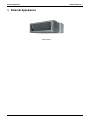
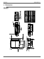
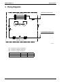
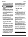
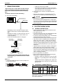
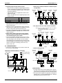
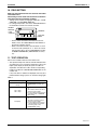
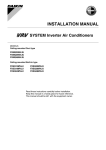
EDUS 39 - 900A - F11_a FXMQ-M Ceiling Mounted Duct Unit AMERICAS EDUS39-900A-F11_a FXMQ-M Ceiling Mounted Duct Unit 1. 2. 3. 4. 5. 6. 7. External Appearance...................................................................................2 Specifications ..............................................................................................3 Dimensions .................................................................................................4 Piping Diagrams..........................................................................................5 Wiring Diagrams..........................................................................................6 Electric Characteristics................................................................................7 Capacity Tables ..........................................................................................8 7.1 Cooling Capacity .......................................................................................... 8 7.2 Heating Capacity .......................................................................................... 9 8. Fan Performances.....................................................................................10 9. Sound Levels ............................................................................................12 10.Center of Gravity .......................................................................................13 11.Installation .................................................................................................14 12.Accessories...............................................................................................25 FXMQ-M 1 External Appearance EDUS39-900A-F11_a 1. External Appearance FXMQ72·96MVJU 2 FXMQ-M EDUS39-900A-F11_a Specifications 2. Specifications Ceiling Mounted Duct Unit Model FXMQ72MVJU FXMQ96MVJU 1 Cooling Capacity Btu/h 72,000 96,000 2 Heating Capacity Btu/h 81,000 108,000 Galvanized Steel Plate Galvanized Steel Plate in. 18’-1/8’’×54’-3/8’’×43’-5/16’’ 18’-1/8’’×54’-3/8’’×43’-5/16’’ 3×26×13 3×26×13 Casing / Color Dimensions: (H×W×D) Coil (Cross Fin Coil) Rows×Stages×FPI Face Area ft² Model Type Fan D13/4G2DA1×2 Sirocco Fan Sirocco Fan W 380×2 380×2 Air Flow Rate (H/L) cfm 2,047/1,764 (H/L) 2,541/2,188 (H/L) Temperature Control Direct Drive Direct Drive Microprocessor Thermostat for Cooling and Heating Microprocessor Thermostat for Cooling and Heating — 5 — 5 in. φ3/8 (Flare Connection) φ3/8 (Flare Connection) Gas Pipes in. φ3/4 (Flare Connection) φ7/8 (Flare Connection) Drain Pipe in. PS1B PS1B Lbs 302 302 Fuse, Thermal Protector for Fan Motor Fuse, Thermal Protector for Fan Motor Electronic Expansion Valve Electronic Expansion Valve Air Filter Liquid Pipes Machine Weight (Mass) Safety Devices Refrigerant Control Connectable outdoor unit Standard Accessories Drawing No. 7.32 D13/4G2DA1×2 Motor Output (High) Drive Piping Connections 7.32 R-410A P Series Operation manual, Installation manual, Sealing pads, Connection pipes, Screws, Clamps R-410A P Series Operation manual, Installation manual, Sealing pads, Connection pipes, Screws, Clamps C:3D065683 Notes: 1 Nominal cooling capacities are based on the following conditions: Return air temperature: 80°FDB, 67°FWB Outdoor temperature: 95°FDB Equivalent ref. piping: 25ft (Horizontal) 2 Nominal heating capacities are based on the following conditions: Return air temperature: 70°FDB. Outdoor temperature: 47°FDB, 43°FWB Equivalent ref. piping: 25ft (Horizontal) 3 Capacities are net, including a deduction for cooling (an addition for heating) for indoor fan motor heat. 4 Static external pressure is changeable to change over the connectors inside electrical box, this pressure means “High static pressureStandard”. 5 Air filter is not standard accessory, but please mount it in the duct system of the suction side. Select its dust collection efficiency (gravity method) 50% or more. FXMQ-M 3 Dimensions EDUS39-900A-F11_a 3. Dimensions C : 3D065655 FXMQ72MVJU FXMQ96MVJU 4 FXMQ-M EDUS39-900A-F11_a Piping Diagrams 4. Piping Diagrams Gas piping connection port Heat exchanger R3T R1T Fan R2T Liquid piping connection port Filter Electronic Filter expansion valve C:4D040157 R1T : Thermistor for suction air temperature R2T : Thermistor for liquid line temperature R3T : Thermistor for gas line temperature FXMQ-M Capacity GAS Liquid 72M φ3/4 φ3/8 96M φ7/8 φ3/8 5 Wiring Diagrams EDUS39-900A-F11_a 5. Wiring Diagrams 3D065414C FXMQ72/96MVJU 6 FXMQ-M EDUS39-900A-F11_a Electric Characteristics 6. Electric Characteristics Units Model FXMQ72MVJU FXMQ96MVJU Power supply IFM Input (W) Hz Volts Voltage range MCA MOP kW FLA Cooling Heating 60 208-230 MAX. 253 MIN. 187 9.5 15 0.380 x 2 7.6 1,490 1,490 10.7 15 0.380 x 2 8.6 1,684 1,684 NOTES: 1. Voltage range: Units are suitable for use on electrical systems where voltage supplied to unit terminals is not below or above listed range limits. 2. Maximum allowable voltage imbalance between phases is 2%. 3. MCA/MOP MCA = 1.25 X FLA MOP < 4 x FLA (next lower standard fuse rating: Min. 15A) 4. Select wire based on the MCA. 5. Instead of a fuse, use a circuit breaker. SYMBOLS: MCA: Minimum Circuit Amps (A) MOP: Maximum Overcurrent Protection (A) kW: Fan Motor Rate Output (kW) FLA: Full Load Amps (A) IFM: Indoor Fan Motor FXMQ-M 7 Capacity Tables EDUS39-900A-F11_a 7. Capacity Tables 7.1 Cooling Capacity FXMQ72MVJU Cooling capacity Indoor (FWB) Outdoor FDB 75 79 83 87 91 95 99 103 61 TC 56.9 56.9 56.9 56.9 56.9 56.9 56.9 56.9 64 SHC 50.8 50.8 50.8 50.8 50.8 50.8 50.8 50.8 TC 64.4 64.4 64.4 64.4 64.4 64.4 64.4 64.4 67 SHC 53.9 53.9 53.9 53.9 53.9 53.9 53.9 53.9 TC 72.0 72.0 72.0 72.0 72.0 72.0 70.7 69.4 70 SHC 56.9 56.9 56.9 56.9 56.9 56.9 56.9 56.9 TC 79.5 78.8 77.3 75.8 74.7 73.4 72.2 70.8 72 SHC 60.1 60.1 60.1 60.1 60.1 60.1 59.0 58.7 TC 81.0 79.5 78.0 77.3 75.8 74.4 73.1 71.8 75 SHC 58.7 58.0 57.3 56.6 56.0 54.9 54.3 53.2 TC 82.5 81.0 79.5 78.8 77.3 75.8 74.5 73.2 SHC 55.6 54.9 54.6 53.9 53.2 52.8 52.2 51.9 FXMQ96MVJU Cooling capacity Indoor (FWB) Outdoor FDB 75 79 83 87 91 95 99 103 61 TC 75.8 75.8 75.8 75.8 75.8 75.8 75.8 75.8 64 SHC 63.8 63.8 63.8 63.8 63.8 63.8 63.8 63.8 TC 85.9 85.9 85.9 85.9 85.9 85.9 85.9 85.9 67 SHC 67.2 67.2 67.2 67.2 67.2 67.2 67.2 67.2 TC 96.0 96.0 96.0 96.0 96.0 96.0 94.3 92.5 70 SHC 71.0 71.0 71.0 71.0 71.0 71.0 71.0 71.7 TC 106.0 105.0 103.0 101.0 99.6 97.9 96.2 94.4 72 SHC 74.7 74.7 74.7 74.7 74.7 74.4 73.7 73.0 TC 108.0 106.0 104.0 103.0 101.0 99.2 97.4 95.7 75 SHC 73.7 73.0 72.0 71.3 70.3 69.3 67.9 66.5 TC 110.0 108.0 106.0 105.0 103.0 101.0 99.3 97.6 SHC 69.7 68.6 67.6 66.9 66.5 65.9 65.5 64.8 TC = Total capacity ; MBh SHC = Sensible heat capacity ; Btu/hr 8 FXMQ-M EDUS39-900A-F11_a 7.2 Capacity Tables Heating Capacity FXMQ72MVJU Heating capacity Indoor (FDB) Outdoor FDB 22.0 26.0 30.0 35.0 39.0 44.0 47.0 51.0 54.0 57.0 60.0 FWB 20.0 24.0 28.0 32.0 36.0 40.0 43.0 47.0 50.0 53.0 56.0 62 TC 72.2 76.5 81.0 85.5 90.8 94.5 94.5 94.5 94.5 94.5 94.5 65 TC 72.1 76.5 81.0 85.5 88.5 88.5 88.5 88.5 88.5 88.5 88.5 68 TC 71.9 75.8 80.3 84.0 84.0 84.0 84.0 84.0 84.0 84.0 84.0 70 TC 71.9 75.8 80.3 81.0 81.0 81.0 81.0 81.0 81.0 81.0 81.0 72 TC 71.8 75.8 78.0 78.0 78.0 78.0 78.0 78.0 78.0 78.0 78.0 75 TC 71.6 73.5 73.5 73.5 73.5 73.5 73.5 73.5 73.5 73.5 73.5 FXMQ96MVJU Heating capacity Indoor (FDB) Outdoor FDB 22.0 26.0 30.0 35.0 39.0 44.0 47.0 51.0 54.0 57.0 60.0 FWB 20.0 24.0 28.0 32.0 36.0 40.0 43.0 47.0 50.0 53.0 56.0 62 TC 96.3 102 108 114 121 126 126 126 126 126 126 65 TC 96.1 102 108 114 118 118 118 118 118 118 118 68 TC 95.9 101 107 112 112 112 112 112 112 112 112 70 TC 95.8 101 107 108 108 108 108 108 108 108 108 72 TC 95.7 101 104 104 104 104 104 104 104 104 104 75 TC 95.5 98.0 98.0 98.0 98.0 98.0 98.0 98.0 98.0 98.0 98.0 TC = Total capacity ; MBh FXMQ-M 9 Fan Performances EDUS39-900A-F11_a 8. Fan Performances FXMQ72MVJU Notes: 1. The remote controller can be used to switch between “high” and “low”. 2. The air flow is set to “standard” before leaving the factory. It is possible to switch between “standard ESP” and “high ESP” by changing the switch in the indoor unit electrical box. 3D065628A 10 FXMQ-M EDUS39-900A-F11_a Fan Performances FXMQ96MVJU Notes: 1. The remote controller can be used to switch between “high” and “low”. 2. The air flow is set to “standard” before leaving the factory. It is possible to switch between “standard ESP” and “high ESP” by changing the switch in the indoor unit electrical box. 3D065629A FXMQ-M 11 Sound Levels (Reference) EDUS39-900A-F11_a 9. Sound Levels (Reference) 9.1 Overall Location of microphone 3.3 ft DUCT DUCT SUCTION 4.9 ft DISCHARGE 6.6 ft MICROPHONE Notes: 1. The operating conditions are assumed to be standard (JIS conditions). Power source 208-230V, 60hz. 2. The operating values were obtained in an anechoic chamber (conversion values). 3. Sound levels will vary depending on a range of factors such as the construction (acoustic absorption coefficient) of the particular room in which the equipment is installed. dBA Model 9.2 208-230V, 60Hz H L FXMQ72MVJU 49.0 46.0 FXMQ96MVJU 49.0 46.0 Octave Band Level 208V-230V, 60Hz FXMQ72MVJU FXMQ96MVJU 4D068573 12 4D068754 FXMQ-M EDUS39-900A-F11_a Center of Gravity 10. Center of Gravity 4D065654 FXMQ-M 13 Installation EDUS39-900A-F11_a 11. Installation 1. SAFETY CONSIDERATIONS Read these “SAFETY CONSIDERATIONS for Installation” carefully before installing air conditioning equipment. After completing the installation, make sure that the unit operates properly during the startup operation. Instruct the customer on how to operate and maintain the unit. Inform customers that they should store this Installation Manual with the Operation Manual for future reference. Always use a licensed installer or contractor to install this product. Improper installation can result in water or refrigerant leakage, electrical shock, fire, or explosion. Meanings of DANGER, WARNING, CAUTION, and NOTE Symbols: DANGER ................ Indicates an imminently hazardous situation which, if not avoided, will result in death or serious injury. WARNING .............. Indicates a potentially hazardous situation which, if not avoided, could result in death or serious injury. CAUTION ............... Indicates a potentially hazardous situation which, if not avoided, may result in minor or moderate injury. It may also be used to alert against unsafe practices. NOTE...................... Indicates situations that may result in equipment or property-damage accidents only. DANGER • Refrigerant gas is heavier than air and replaces oxygen. A massive leak can lead to oxygen depletion, especially in basements, and an asphyxiation hazard could occur leading to serious injury or death. • Do not ground units to water pipes, gas pipes, telephone wires, or lightning rods as incomplete grounding can cause a severe shock hazard resulting in severe injury or death. Additionally, grounding to gas pipes could cause a gas leak and potential explosion causing severe injury or death. • If refrigerant gas leaks during installation, ventilate the area immediately. Refrigerant gas may produce toxic gas if it comes in contact with fire. Exposure to this gas could cause severe injury or death. • After completing the installation work, check that the refrigerant gas does not leak throughout the system. • Do not install unit in an area where flammable materials are present due to risk of explosions that can cause serious injury or death. • Safely dispose all packing and transportation materials in accordance with federal/state/local laws or ordinances. Packing materials such as nails and other metal or wood parts, including plastic packing materials used for transportation may cause injuries or death by suffocation. 14 WARNING • Only qualified personnel must carry out the installation work. Installation must be done in accordance with this installation manual. Improper installation may result in water leakage, electric shock, or fire. • When installing the unit in a small room, take measures to keep the refrigerant concentration from exceeding allowable safety limits. Excessive refrigerant leaks, in the event of an accident in a closed ambient space, can lead to oxygen deficiency. • Use only specified accessories and parts for installation work. Failure to use specified parts may result in water leakage, electric shocks, fire, or the unit falling. • Install the air conditioner on a foundation strong enough that it can withstand the weight of the unit. A foundation of insufficient strength may result in the unit falling and causing injuries. • Take into account strong winds, typhoons, or earthquakes when installing. Improper installation may result in the unit falling and causing accidents. • Make sure that a separate power supply circuit is provided for this unit and that all electrical work is carried out by qualified personnel according to local state, and national regulations. An insufficient power supply capacity or improper electrical construction may lead to electric shocks or fire. • Make sure that all wiring is secured, that specified wires are used, and that no external forces act on the terminal connections or wires. Improper connections or installation may result in fire. • When wiring, position the wires so that the electrical components box lid can be securely fastened. Improper positioning of the electrical components box lid may result in electric shocks, fire, or the terminals overheating. • Before touching electrical parts, turn off the unit. • Be sure to install a ground fault circuit interrupter if one is not already available. This helps prevent electrical shocks or fire. • Securely fasten the outside unit terminal cover (panel). If the terminal cover/panel is not installed properly, dust or water may enter the outside unit causing fire or electric shock. • When installing or relocating the system, keep the refrigerant circuit free from substances other than the specified refrigerant (R-410A) such as air. Any presence of air or other foreign substance in the refrigerant circuit can cause an abnormal pressure rise or rupture, resulting in injury. FXMQ-M EDUS39-900A-F11_a • Do not change the setting of the protection devices. If the pressure switch, thermal switch, or other protection device is shorted and operated forcibly, or parts other than those specified by Daikin are used, fire or explosion may occur. CAUTION • Do not touch the switch with wet fingers. Touching a switch with wet fingers can cause electric shock. • Do not allow children to play on or around the unit to prevent injury. • Do not touch the refrigerant pipes during and immediately after operation as the refrigerant pipes may be hot or cold, depending on the condition of the refrigerant flowing through the refrigerant piping, compressor, and other refrigerant cycle parts. Your hands may suffer burns or frostbite if you touch the refrigerant pipes. To avoid injury, give the pipes time to return to normal temperature or, if you must touch them, be sure to wear proper gloves. • Heat exchanger fins are sharp enough to cut. To avoid injury wear glove or cover the fins when working around them. • Install drain piping to proper drainage. Improper drain piping may result in water leakage and property damage. • Insulate piping to prevent condensation. • Be careful when transporting the product. • Do not turn off the power immediately after stopping operation. Always wait for at least 5 minutes before turning off the power. Otherwise, water leakage may occur. • Do not use a charging cylinder. Using a charging cylinder may cause the refrigerant to deteriorate. • Refrigerant R-410A in the system must be kept clean, dry, and tight. (a)Clean and Dry -- Foreign materials (including mineral oils such as SUNISO oil or moisture) should be prevented from getting into the system. (b)Tight -- R-410A does not contain any chlorine, does not destroy the ozone layer, and does not reduce the earth’s protection again harmful ultraviolet radiation. R-410A can contribute to the greenhouse effect if it is released. Therefore take proper measures to check for the tightness of the refrigerant piping installation. Read the chapter Refrigerant Piping and follow the procedures. • Since R-410A is a blend, the required additional refrigerant must be charged in its liquid state. If the refrigerant is charged in a state of gas, its composition can change and the system will not work properly. • The indoor unit is for R-410A. See the catalog for indoor models that can be connected. Normal operation is not possible when connected to other units. FXMQ-M Installation • Remote controller (wireless kit) transmitting distance can be shorter than expected in rooms with electronic fluorescent lamps (inverter or rapid start types). Install the indoor unit far away from fluorescent lamps as much as possible. • Indoor units are for indoor installation only. Outdoor units can be installed either outdoors or indoors. • Do not install the air conditioner in the following locations: (a)Where a mineral oil mist or oil spray or vapor is produced, for example, in a kitchen. Plastic parts may deteriorate and fall off or result in water leakage. (b)Where corrosive gas, such as sulfurous acid gas, is produced. Corroding copper pipes or soldered parts may result in refrigerant leakage. (c)Near machinery emitting electromagnetic waves. Electromagnetic waves may disturb the operation of the control system and cause the unit to malfunction. (d)Where flammable gas may leak, where there is carbon fiber, or ignitable dust suspension in the air, or where volatile flammables such as thinner or gasoline are handled. Operating the unit in such conditions can cause a fire. • Take adequate measures to prevent the outside unit from being used as a shelter by small animals. Small animals making contact with electrical parts can cause malfunctions, smoke, or fire. Instruct the customer to keep the area around the unit clean. NOTE • Install the power supply and control wires for the indoor and outdoor units at least 3.5 feet away from televisions or radios to prevent image interference or noise. Depending on the radio waves, a distance of 3.5 feet may not be sufficient to eliminate the noise. • Dismantling the unit, treatment of the refrigerant, oil and additional parts must be done in accordance with the relevant local, state, and national regulations. • Do not use the following tools that are used with conventional refrigerants: gauge manifold, charge hose, gas leak detector, reverse flow check valve, refrigerant charge base, vacuum gauge, or refrigerant recovery equipment. • If the conventional refrigerant and refrigerator oil are mixed in R-410A, the refrigerant may deteriorate. • This air conditioner is an appliance that should not be accessible to the general public. • The wall thickness of field-installed pipes should be selected in accordance with the relevant local, state, and national regulations. 15 Installation 2. BEFORE INSTALLATION • When moving the unit while removing it from the carton box, be sure to lift it by holding on to the four lifting lugs without exerting any pressure on other parts, especially, the refrigerant piping, drain piping, and other resin parts. • Be sure to check the type of R410A refrigerant to be used before installing the unit. (Using an incorrect refrigerant will prevent normal operation of the unit.) • The accessories needed for installation must be retained in your custody until the installation work is completed. Do not discard them! • Decide upon a line of transport. • Leave the unit inside its packaging while moving, until reaching the installation site. Where unpacking is unavoidable, use a sling of soft material or protective plates together with a rope when lifting, to avoid damage or scratches to the unit. • When moving the unit at or affter opening, hold the unit by the hanger brackets (× 4). Do not apply force to the refrigerant piping, drain piping or plastic parts. • For the installation of an outdoor unit, refer to the installation manual attached to the outdoor unit. • Do not install or operate the unit in rooms mentioned below. • Laden with mineral oil, or filled with oil vapor or spray like in kitchens. (Plastic parts may deteriorate which could eventually cause the unit to fall out of place, or could lead to leaks.) • Where corrosive gas like sulfurous gas exists. (Copper tubing and brazed spots may corrode which could eventually lead to refrigerant leaks.) • Where exposed to combustible gases and where volatile flammable gas like thinner or gasoline is used. (Gas in the vicinity of the unit could ignite.) • Where machines can generate electromagnetic waves. (Control system may malfunction.) • Where the air contains high levels of salt such as that near the ocean and where voltage fluctuates greatly such as that in factories. Also in vehicles or vessels. • This unit, both indoor and outdoor, is suitable for installation in a commercial and light industrial environment. If installed as a household appliance it could cause electromagnetic interference. 2-1 PRECAUTIONS • Be sure to read this manual before installing the indoor unit. • Entrust installation to the place of purchase or a qualified serviceman. Improper installation could lead to leaks and, in worse cases, electric shock of fire. • Use only parts provided with the unit or parts satisfying required specifications. Unspecified parts could cause the unit to fall out of place, or could lead to leaks and, in worse cases, electric shock or fire. • Be sure to mount an air filter (part to be procured in the field) in the suction air passage in order to prevent water leaking, etc. 16 EDUS39-900A-F11_a 2-2 ACCESSORIES Check the following accessories are included with your unit. Name Attached piping (1) Insulation tube (2) Quantity 1 set 2 pcs. Shape 2-3 (Other) (3) Operation manual (4) Installation manual (5) Screws for flange connection (M5) (48 pcs.) (6) Insulation material (for hanger) (2 pcs.) (7) Washers (8 pcs.) (8) Clamps (6 pcs.) (9) Hexagon head bolt for pipe frange (M10) (2 pcs.) (10) Spring washer for pipe frange (M10) (2 pcs.) OPTIONAL ACCESSORIES • A wired remote controller is necessary for this unit separately. NOTE • If you wish to use a remote controller that is different from the above, select a suitable remote controller after consulting catalogs and technical materials. FOR THE FOLLOWING ITEMS, TAKE SPECIAL CARE DURING CONSTRUCTION AND CHECK AFTER INSTALLATION IS FINISHED. a. Items to be checked after completion of work Items to be checked If not properly done, what is likely to occur. Are the indoor and outdoor unit fixed firmly? The units may drop, vibrate or make noise. Is the gas leak test finished? It may result in insufficient cooling. Is the unit fully insulated? Condensate water may drip. Check Dose drainage flow smoothly? Condensate water may drip. Dose the power supply voltage The unit may malfunction or correspond to that shown on the components burn out. the name plate? Are wiring and piping correct? The unit may malfunction or the components burn out. Is the unit safely grounded? Dangerous at electric leakage. Is wiring size according to specifications? The unit may malfunction or the components burn out. Is something blocking the air outlet or inlet of either the indoor or outdoor units? It may result in insufficient cooling. Are refrigerant piping length and additional refrigerant charge noted down? The refrigerant charge in the system is not clear. FXMQ-M EDUS39-900A-F11_a Installation b. Items to be checked at time of delivery Also review the “SAFETY CONSIDERATIONS” Items to be checked Check Did you explain about operations while showing the instruction manual to your customer? (2) Use suspension bolts for installation. Check whether the ceiling is strong enough to support the weight of the unit or not. If there is a risk, reinforce the ceiling before installing the unit. 18-1/2 Did you hand the instruction manual over to your customer? c. Points for explanation about operations The items with WARNING and CAUTION marks in the instruction manual are the items pertaining to possibilities for bodily injury and material damage in addition to the general usage of the product. Accordingly, it is necessary that you make a full explanation about the described contents and also ask your customers to read the instruction manual. 3. SELECTING INSTALLATION SITE Fig. 1 4. PREPARATIONS BEFORE INSTALLATION (1) Relative positions of indoor unit and suspension bolt. (Refer to Fig. 2) Suspension bolt (× 4) Please attach additional thermal insulation material to the unit body when it is believed that the relative humidity in the ceiling exceeds 80%. Use glass wool, polyethylene foam, or similar with a thickness of 3/8in. or more as thermal insulation material. CAUTION 45-3/16 43-5/16 Indoor unit Air inlet Air outlet 25-9/16 or more (service space) (1) Select an installation site where the following conditions are fulfilled and that meets with your customer’s approval. • In the upper space (including the back of the ceiling) of the indoor unit where there is no possible dripping of water from the refrigerant pipe, drain pipe, water pipe, etc. • Where optimum air distribution can be ensured. • Where nothing blocks the air passage. • Where condensate can be properly drained. • If supporting structural members are not strong enough to take the unit’s weight, the unit could fall out of place abd cause serious injury. • Where the false ceiling is not noticeably on an incline. • Where there is no risk of flammable gas leakage. • Where sufficient clearance for maintenance and service can be ensured. (Refer to Fig. 1) • Where piping between indoor and outdoor units is possible within the allowable limit. (Refer to the installation manual of the outdoor unit.) (length: in.) 51 54-5/16 NOTE TO INSTALLER • Be sure to instruct customers how to properly operate the unit (especially cleaning filters, operating different functions, and adjusting the temperature) by having them carry out operations themselves while looking at the manual. (service space) Approx. 5-7/8 2-4 Min. 25-9/16 43-5/16 or more (service space) Fig. 2 Inspection hatch 23-5/8 (length: in.) (2) Install a canvass duct to the air discharge outlet and air inlet so that vibration from the machine body isn’t transmitted to the duct or ceiling. You should also apply acoustic (insulation material) to the inside of the duct, and vibration insulation rubber to the suspension bolts. • Install the indoor and outdoor units, power supply wiring and connecting wires at least 3.3ft. away from televisions or radios in order to prevent image interference or noise. (Depending on the radio waves, a distance of 3.3ft. may not be sufficient enough to eliminate the noise.) FXMQ-M 17 Installation EDUS39-900A-F11_a (3) Install suspension bolts. (Use bolts of 3/8in. diameter.) • Install the equipment where supporting structures are strong enough to bear the equipment’s weight. Use embedded inserts or anchor bolts with new buildings and hole-in-anchors with old buildings. Installation example Ceiling slab Anchor Long nut or turn-buckle Suspension bolt Indoor unit Note) All the above parts are field supplied. 5. INDOOR UNIT INSTALLATION Installing optional accessories before installing the indoor unit is easier. As for the parts to be used for installation work, be sure to use the provided accessories and specified parts designated by our company. (1) Fix the hanger bracket to the suspension bolt. Tighten both upper and lower nuts firmly using washers. Part to be procured in the field Washer (accessory (7)) Tighten from above and below (Double nut) (2) Adjust the height of the unit. (3) Make sure the unit is level. • Level the unit with a level when installing. If the unit is not level, it A could become the source of water leaks. • When leveling the unit, check all four corners with a level or a vinyl tube containing water. (See the figure on the right.) Level A B Vinyl tube Hanger bracket setting bolt Insulation material (accessory (6)) Hanger bracket setting bolt B A-A cross-section Setting the unit at an angle opposite to the drain piping might cause leaks. 6. REFRIGERANT PIPING WORK For refrigerant piping of outdoor units, see the installation manual attached to the outdoor unit. Execute heat insulation work completely on both sides of the gas piping and the liquid piping. Otherwise, a water leakage can result. Be sure to use insulation that is designed for use with HVAC Systems. in cases where the temperature and humidity of the refrigerant piping sections might exceed 86°F or RH80%, reinforce the refrigerant insulation. (3/4in. or thicker) Condensation may form on the surface of the insulating material. Before refrigerant piping work, check which type of refrigerant is used. Proper operation is not possible if the types of refrigerant are not the same. CAUTION • Use a pipe cutter and flare suitable for the type of refrigerant. • Apply ester oil or ether oil inside the flare portions before connecting. • To prevent dust, moisture or other foreign matter from infiltrating the tube, either pinch the end or cover it with tape. • Do not allow anything other than the designated refrigerant to get mixed into the refrigerant circuit, such as air, etc. If any refrigerant gas leaks while working on the unit, ventilate the room thoroughly right away. • The outdoor unit is charged with refrigerant. • Be sure to use both a spanner and torque wrench together, as shown in the drawing, when connecting or disconnecting pipes to/from the unit. • To prevent flare nut cracking and gas leaks, be sure to use both a spanner and torque wrench together, as shown in the drawing below, when connecting or disconnecting pipes to/from the unit. • Refer to the Table 1 for the dimensions of flare nut spaces. • When connecting the flare nut, coat the flare section inside with ester oil or ether oil, rotate three or four times first, then screw in. • Refer to the Table 1 for tightening torque. • Ventilate if refrigerant gas leaks while performing work. Table 1 Pipe size Tightening torque (ft.lbf) Flare dimensions A (in.) φ 1/4” 10.4 - 12.7 0.342 - 0.358 φ 3/8” 24.1 - 29.4 0.504 - 0.520 φ 1/2” 36.5 - 44.5 0.638 - 0.654 φ 5/8” 45.6 - 55.6 0.760 - 0.776 Flare shape (in.) R0.0160.031 18 0 45 ±2 A 0 90 ±2 (4) Tighten the nuts on the top. (5) Insulate the two hanger brackets on the discharge side with the insulation material. Insulate the edges so that the surface and edges of the hanger brackets cannot be seen. 0 0 B-B cross-section CAUTION FXMQ-M EDUS39-900A-F11_a Installation NOTE The flare nuts used must be those included with the main body. Ester oil or ether oil. • Connect refrigerant piping and branching according to the attached installation manuals that come with the outdoor unit. Indoor units to be connected Gas piping diameter FXMQ72MVJU φ3/4 Use attached piping. FXMQ96MVJU φ7/8 Use attached piping. Liquid piping diameter φ3/8 CAUTION CAUTION TO BE TAKEN WHEN BRAZING REFRIGERANT PIPING Do not use flux when brazing refrigerant piping. Therefore, use the phosphor copper brazing filler metal (BCuP2/ B-Cu93P-710/795) which does not require flux. (Flux has extremely harmful infulence on refrigerant piping sysems. For instance, if the chlorine based flux is used, it will cause pipe corrosion or, in particular, if the flux contains fluorine, it will damage the refrigerant oil.) Torque wrench Spanner Piping union Flare nut CAUTION Over-tightening may damage the flare and cause a refrigerant leakage. Use “ Table 2 ” as a reference if a torque wrench is not available. Once work is complete, make sure there is no gas leaking. As the flare nut is tightened with the wrench, the torque will suddenly increase. From that position, tighten the nut to the angle shown on “ Table 2 ”. • After checking the pipe-connection for gas leakage, be sure to insulate the liquid and gas piping, referring to the figure below. • Wrap the sealing pad (field supply) only around the insulation for the joints on the gas piping side. • Before brazing local refrigerant piping, nitrogen gas shall be blown through the piping to expel air from the piping. If your brazing is done without nitrogen gas blowing, a large amount of oxide film develops inside the piping, and could cause system malfunction. • When brazing the refrigerant piping, only begin brazing after having carried out nitrogen substitution or while inserting nitrogen into the refrigerant piping. Once this is done, connect the indoor unit with a flared or a flanged connection. • Nitrogen should be set to 2.90PSI with a pressure-reducing valve if brazing while inserting nitrogen into the piping. Refrigerant piping Pressurereducing valve Part to be brazed CAUTION Sealing pad (Field supply) (accessory (8)) Insulation for fitting (Field supply) (for gas line) Gas pipe Liquid pipe NOTE • Attached piping is needed for connecting gas piping. Use attached piping according to the size of the piping to be connected. When connecting the included piping, use the included piping flange hex bolts accessory (9) and spring washers accessory (10). FXMQ-M hands valve Nitrogen Be sure to insulate any field piping all the way to the piping connection inside the unit. Any exposed piping may cause condensation or burns if touched. Clamp Taping Nitrogen Not recommendable but in case of emergency You must use a torque wrench but if you are obliged to install the unit without a torque wrench, you may follow the installation method mentioned below. After the work is finished, make sure to check that there is no gas leak. When you keep on tightening the flare nut with a spanner, there is a point where the tightening torque suddenly increases. From that position, further tighten the flare nut the angle shown below: Table 2 Pipe size Further tightening angle Recommended arm length of tool φ 1/4” 60 to 90 degrees Approx. 5-7/8in. φ 3/8” 60 to 90 degrees Approx. 7-7/8in. φ 1/2” 30 to 60 degrees Approx. 9-13/16in. φ 5/8” 30 to 60 degrees Approx. 11-3/16in. 19 Installation 7. EDUS39-900A-F11_a DRAIN PIPING WORK Rig the drain pipe as shown below and take measures against condensation. Improperly rigged piping could lead to leaks and eventually wet furniture and belongings. Insulate the drain hose inside the building. (1) Carry out the drain piping. • A drain trap need not be installed. • The diameter of the piping is the same as that of the connecting pipe (PS1B), and should be kept equal to or greater than that of the connecting pipe. (2) After piping work is finished, check drainage flows smoothly. • Open the water supply port, add appximately 61in3. of water slowly into the drain pan and check drainage flow. CAUTION Attached drain hose Bottom of unit • Drain piping connections Do not connect the drain piping directly to sewage pipes that smell of ammonia. The ammonia in the sewage might enter the indoor unit through the drain pipes and corrode the heat exchanger. 8. 8-1 • Keep piping as short as possible and slope it downwards so that air may not remaine trapped inside the pipe. • Keep pipe size equal to or greater than that of the connecting pipe (Vinyl pipe of 1in. nominal diam. and 1-1/4in. outer diam.). • Insulate the clamp metal with the sealing pad. Metal clamp (Field supply) Sealing pad (Field supply) Drain hose 1/8in. or less Metal clamp Tape Drain hose • In order to prevent foreign matter from building up inside the piping, you should avoid curves as much as possible. NOTE 3-15/16in. or more • If converging multiple drain pipes, install according to the procedure shown below. ELECTRIC WIRING WORK GENERAL INSTRUCTIONS • All field supplied parts and materials and electric works must conform to local codes. • Use copper wire only. • For electric wiring work, refer to also “Wiring diagram label” attached to the electrical components box lid. • For remote controller wiring details, refer to the installation manual attached to the remote controller. • All wiring must be performed by an authorized electrician. • This system consists of multiple indoor units. Mark each indoor unit as unit A, unit B..., and be sure the terminal board wiring to the outdoor unit and BS unit are properly matched. If wiring and piping between the outdoor unit and an indoor unit are mismatched, the system may cause a malfunction. • A ground fault circuit interrupter capable of shutting down power supply to the entire system must be installed. • Refer to the installation manual attached to the outdoor unit for the size of power supply wiring connected to the outdoor unit, the capacity of the ground fault circuit interrupter and switch, and wiring instructions. • Be sure to ground the air conditioner. • Do not connect the ground wire to gas and water pipes, lightning rods, or telephone ground wires. • Gas pipes : might cause explosions or fire if gas leaks. • Water pipes : no grounding effect if hard vinyl piping is used. • Telephone ground wires or lightning rods : might cause abnormally high electric potential in the ground during lighting storms. 8-2 ELECTRICAL CHARACTERISTICS Units Model Hz Volts Voltage range 60 208230 Max. 253 Min. 187 FXMQ72MVJU FXMQ96MVJU Power supply Fan motor MCA MOP W FLA 9.5 15 380×2 7.6 10.7 15 380×2 8.6 MCA: Minimum Circuit Amps (A); MOP: Maximum Overcurrent Protection; kW: Fan Motor Rated Output (kW); FLA: Full Load Amps (A) 20 FXMQ-M EDUS39-900A-F11_a 8-3 Installation SPECIFICATIONS FOR FIELD SUPPLIED FUSES AND WIRE Power supply wiring Model Breaker FXMQ72MVJU 15A FXMQ96MVJU Size Size must comply with local codes. Remote controller wiring Transmission wiring Wire Size 2-conductor, stranded nonshielded copper cable/ PVC or vinyl jacket AWG 18-2, Max: 1640 ft. Power supply wiring Clamp or (accessory (8)) Transmission wiring Insulation tube (accessory (2)) (3in.) Terminal block for remote controller Remote controller wiring Ground terminal NOTE 1. Allowable length of transmission wiring between indoor/ outdoor units and between the indoor unit and the remote controller is as follows. (1) Outdoor unit – Indoor unit: Max. 3280ft. (Total wiring length: 6560ft.) (2) Indoor unit – Remote controller: Max. 1640ft. 9. 9-1 WIRING EXAMPLE AND HOW TO SET THE REMOTE CONTROLLER HOW TO CONNECT WIRINGS (Remove the electrical components box lid and wire as shown in the figure below.) Conduit (Field supply) Lock nut (Field supply) Remote controller wiring (*) (Field wiring) Transmission wiring (*) (Field wiring) Power supply wiring (*) (Field wiring) Electrical components box lid Ground wiring Clamp (accessory(8)) Wiring (*) (Remote controller and transmission) Wire locking bracket Routing power supply wiring and transmission wiring Let the power supply wiring with a conduit pass through one of the holes on the side cover, and let the transmission wiring with a conduit pass through another hole. • For protection from uninsulated live parts, thread the power supply wiring or the transmission wiring through the included insulation tube and secure it with the included clamp. X2M X1M Clamp (accessory (8)) Insulation tube Power supply wiring (accessory (2)) and ground wiring Transmission wiring CAUTION • Be sure to attach the sealing material or putty (field supplied) to hole of wiring to prevent the infiltration of water as well as any insects and other small creatures from outside. Otherwise a short-circuit may occur inside the electrical components box. • When clamping the wires, be sure no pressure is applied to the wire connections by using the included clamping material to make appropriate clamps. Also, when wiring, make sure the lid on the electrical components box fits snugly by arranging the wires neatly and attaching the electrical components box lid firmly. When attaching the electrical components box lid, make sure no wires get caught in the edges. Pass wiring through the wiring through holes to prevent damage to them. • Make sure the remote controller wiring, the wiring between the units, and other electrical wiring do not pass through the same locations outside of the unit, separating them by at least 2in., otherwise electrical noise (external static) could cause mistaken operation or breakage. [ PRECAUTIONS ] 1. Use round crimp-style terminals for connecting wires to the power supply terminal block. If unavailable, observe the following points when wiring. • Do not connect wires of different gauge to the same power supply terminal. (Looseness in the connection may cause overheating.) • Use the specified electric wire. Connect the wire securely to the terminal. Lock the wire down without applying excessive force to the terminal. (Tightening torque: 0.97ft·lbf ±10 %) Attach insulation sleeve Round crimp-style terminal FXMQ-M Power supply terminal block Insulation tube (accessory (2)) Electric wire 21 Installation EDUS39-900A-F11_a 2. Tightening torque for the terminal screws. • Use the correct screwdriver for tightening the terminal screws. If the blade of screwdriver is too small, the head of the screw might be damaged, and the screw will not be properly tightened. • If the terminal screws are tightened too hard, screws might be damaged. • Refer to the table below for the tightening torque of the terminal screws. 1. When using 1 remote controller for 1 indoor unit. (Normal operation) Power supply 208-230V 60Hz Control box IN/D OUT/D F1 F2 F1 F2 L1 L2 L1 L2 L1L2 P1 P2 F1 F2 T1 T2 Power supply 208-230V L1 L2 60Hz No. 1 System Terminal Size Tightening torque (ft·lbf) Terminal block for remote controller (6P) M3.5 0.58 - 0.72 1.76 - 2.15 M5 Power supply terminal block 2.23 - 3.01 M5 Ground terminal 3. Do not connect wires of different gauge to the same grounding terminal. Looseness in the connection may deteriorate protection. 4. Outside of the unit, keep transmission wiring at least 2in. away from power supply wiring. The equipment may malfunction if subjected to electrical (external) noise. 5. For remote controller wiring, refer to the “INSTALLATION MANUAL OF REMOTE CONTROLLER” attached to the remote controller. 6. Never connect power supply wiring to the terminal block for remote controller wiring. A mistake of the sort could damage the entire system. 7. Use only specified wire and tightly connect wires to terminals. Be careful wires do not place external stress on terminals. Keep wiring in neat order and so as not to obstruct other equipment such as popping open the electrical components box lid. Make sure the lid closes tight. Incomplete connections could result in overheating, and in worse case, electric shock or fire. Power supply 208-230V Outdoor unit L1L2 P1 P2 F1 F2 T1 T2 P1 P2 P1 P2 COMPLETE SYSTEM EXAMPLE (3 SYSTEMS) Power supply Power supply wiring Transmission wiring Main switch L1L2 P1 P2 F1 F2 T1 T2 P1 P2 P1 P 2 Most downstream Indoor unit 2. For group control or use with 2 remote controllers Note: It is not necessary to designate indoor unit address when using group control. The address is automatically set when power is activated. Power supply Power supply Outdoor 208-230V 208-230V unit Control box 60Hz 60Hz Power supply 208-230V IN/D OUT/D F1 F2 F1 F2 L1 L2 60Hz L1 L2 Power supply 208-230V 60Hz L1 L2 L1 L2 No. 2 System L1 L2 Most downstream indoor unit L1 L2 P1 P2 F1 F2 T1 T2 P1 P2 F1 F2 T1 T2 Indoor unit B Indoor unit A L1 L2 L1 L2 P1 P 2 F1 F2 T1 T2 P1 P 2 F1 F2 T1 T2 Indoor unit C P1 P2 P1 P2 9-2 WIRING EXAMPLE • Fit the power supply wiring of each unit with a switch and fuse as shown in the drawing. P1 P2 F1 F2 T1 T2 60Hz Indoor unit C Indoor unit B Indoor unit A L1 L2 60Hz L1L2 Power supply 208-230V P1 P2 For use with 2 remote controllers Fig. 3 3. When including BS unit Power supply 208-230V 60Hz L1 L2 Power supply 208-230V Outdoor unit Control box IN/D OUT/D F1 F 2 F 1 F 2 No. 3 System Switch BS unit L1 L2 60Hz BS unit Control box Control box OUT/D IN/D F 1 F2 F1 F2 OUT/D IN/D F1 F 2 F1 F 2 Fuse Indoor unit A L1 L2 P1 P2 F1 F2 T1 T2 L1 L2 P 1 P 2 F 1 F 2 T1 T 2 BS unit (Only for Heat recovery system) P1 P2 Indoor unit Remote controller 22 Most downstream indoor unit P1 P2 [ PRECAUTIONS ] 1. A single switch can be used to supply power to units on the same system. However, branch switches and branch ground fault circuit interrupters must be selected carefully. 2. Do not ground the equipment on gas pipes, water pipes or lightning rods, or crossground with telephones. Improper grounding could result in electric shock. FXMQ-M EDUS39-900A-F11_a 9-3 Installation CONTROL BY 2 REMOTE CONTROLLERS (Controlling 1 indoor unit by 2 remote controllers) • When using 2 remote controllers, one must be set to “MAIN” and the other to “SUB”. 9-4 COMPUTERISED CONTROL (FORCED OFF AND ON/OFF OPERATION) (1) Wire specifications and how to perform wiring • Connect the input from outside to terminals T1 and T2 of the terminal block for remote controller. MAIN/SUB CHANGEOVER (1) Insert a screw driver into the recess between the upper and lower part of remote controller and, working from the 2 positions, pry off the upper part. The remote controller PC board is attached to the upper part of remote controller. Upper part of remote controller Lower part of remote controller Insert the screwdriver here and gently work off the upper part of remote controller. (2) Turn the MAIN/SUB changeover switch on one of the two remote controller PC boards to “S”. (Leave the switch of the other remote controller set to “M”.) (Factory setting) T1 T2 FORCED OFF Input A Wire specification Sheathed vinyl cord or cable (2 wire) Gauge AWG18-16 Length Max. 328ft. External terminal Contact that can ensure the minimum applicable load of 15 V DC, 1 mA. (2) Actuation • The following table explains FORCED OFF and ON/ OFF OPERATIONS in response to Input A. FORCED OFF ON/OFF OPERATION Input “ON” stops operation (impossible by remote controllers.) Input OFF → ON turns ON unit. Input OFF enables control by remote controller. Input ON → OFF turns OFF unit. (3) How to select FORCED OFF and ON/OFF OPERATION • Turn the power on and then use the remote controller to select operation. S M Remote controller PC board Only one remote controller needs to be changed if factory settings have remained untouched. F2 S M 9-5 CENTRALIZED CONTROL • For centralized control, it is necessary to designate the group No. For details, refer to the manual of each optional controllers for centralized control. Wiring Method (See ‘‘ELECTRIC WIRING WORK’’) (3) Remove the electrical components box lid (4) Add remote control 2 (slave) to the terminal block for remote controller (P1, P2) in the electrical components box. (There is no polarity.) (Refer to Fig. 3 and 8-3.) FXMQ-M 23 Installation EDUS39-900A-F11_a 10. FIELD SETTING Make sure the terminal box lids are closed on the indoor and outdoor units. Field setting must be made from the remote controller in accordance with the installation condition. • Setting can be made by changing the “Mode No.”, “FIRST CODE NO.”, and “SECOND CODE NO.”. • For setting and operation, refer to the “FIELD SETTING” in the installation manual of the remote controller. SECOND CODE NO. MODE NO. FIRST CODE NO. SETTING FIELD SET MODE • Set the remote controller to the field set mode. For details, refer to the “HOW TO SET IN THE FIELD”, in the remote controller manual. • When in the field set mode, select mode No. 12, then set the first code (switch) No. to “1”. Then set second code (position) No. to “01” for FORCED OFF and “02” for ON/OFF OPERATION. (FORCED OFF at factory set) 11. TEST OPERATION Refer to the installation manual of the outdoor unit. • The operation lamp of the remote controller will flash when an malfunction occurs. Check the malfunction code on the liquid crystal display to identify the point of trouble. An explanation of malfunction codes and the corresponding trouble is provided in “CAUTION FOR SERVICING” of the outdoor unit. If any of the items in Table 3 are displayed, there may be a problem with the wiring or power, so check the wiring again. Table 3 Remote control display Content “Concentrated Management” • There is a short circuit at the FORCED OFF terminals (T1, is lit up T2) “U4” is lit up “UH” is lit up • The power on the outdoor unit is off. • The outdoor unit has not been wired for power supply. • Incorrect wiring for the transmission wiring and / or FORCED OFF wiring. No display • The power on the indoor unit is off. • The indoor unit has not been wired for power supply. • Incorrect wiring for the remote controller wiring, the transmission wiring and / or the FORCED OFF wiring. 3P086156-13Y 24 FXMQ-M EDUS39-900A-F11_a Accessories 12. Accessories Standard Accessories Name Attached piping (1) Insulation tube (2) Quantity 1 set 2 pcs. Shape (Other) (3) Operation manual (4) Installation manual (5) Screws for flange connection (M5) (48 pcs.) (6) Insulation material (for hanger) (2 pcs.) (7) Washers (8 pcs.) (8) Clamps (6 pcs.) (9) Hexagon head bolt for pipe frange (M10) (2 pcs.) (10) Spring washer for pipe frange (M10) (2 pcs.) 3P086156-13Y Optional Accessories (For Unit) Type FXMQ72MVJU Item High efficiency filter 65% KAFJ372L280 90% KAFJ373L280 Filter chamber KDJ3705L280 Long life replacement filter KAFJ371L280 FXMQ96MVJU 3D065676 Optional Accessories (For Controls) : Refer to booklet of “Controls”. FXMQ-M 25 Accessories 26 EDUS39-900A-F11_a FXMQ-M AMERICAS 1645 Wallace Drive, Suite 110 Carrollton, TX75006 [email protected] www.daikinac.com August 2010 EDUS39-900A-F11_a Printed in U.S.A. 08/10 AK·FS.K