1
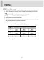
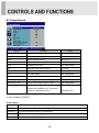
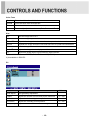
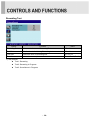
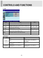
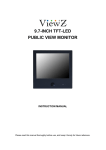
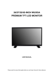
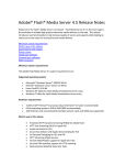
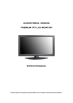
23 & 27 & 32-INCH TFT-LCD IP PUBLIC VIEW MONITOR INSTRUCTION MANUAL Please read this manual thoroughly before use, and keep it handy for future reference. ………………………………………………………….…… 2~3 …………………………………………………………….......................... 4 ……………………………....................... 5 ……………………………………………………………............................... 6 CONNECTING WITH EXTERNAL EQUIPMENT …..………………………………… 7 ………………………………………………………………… 8 ……………………………………………………….. 9 ~ 18 CAMERA CONTROLS AND FUNCTIONS …………………….……………………….. MOUNTING GUIDE …………………………………………………………………….. 19 ~ 27 28 SAFETY INSTRUCTION CAUTIONS FCC RF INTERFERENCE STATEMENT WIRING REMOTE FUNCTIONS CONTROLS AND FUNCTIONS ………………………………………… 29 ……………………………………………………………… 30 ……………………………………………………………………… 31 ~ 33 …………………………………………………......... 34 D-SUB CONNECTOR PIN ASSIGNMENTS POWER MANAGEMENT SPECIFICATIONS TROUBLE SHOOTING GUIDE This Monitor was Manufactured by ISO 9001 Certified Factory -1- Important Safety Instruction 1. Read these instructions. 2. Keep these Instructions. 3. Heed all warnings. 4. Follow all instructions. 5. Do not use this apparatus near water. 6. Clean only with dry cloth. 7. Do not block any ventilation openings. Install in accordance with the manufacturer‟s instructions. 8. Do not install near any heat sources such as radiators, heat registers,stoves, or other apparatus (including amplifiers) that produce heat. 9. Do not defeat the safety purpose of the polarized or grounding-type plug. Apolarized plug has two blades with one wider than the other. Agrounding type plug has two blades and a third grounding prong. The wide blade or the third prong are provided for your safety. If the provided plug does not fit into your outlet, consult an electrician for replacement of the bsolete outlet. 10. Protect the power cord from being walked on or pinched particularly at plugs, convenience receptacles and the point where they exit from the apparatus. 11. Only use attachment/accessories specified by the manufacturer. 12. Use only with the cart, stand, tripod, bracket or table specified by the manufacturer or sold with the apparatus. When a cart is used, use caution when moving the cart/apparatus combination to avoid injury from tip-over. 13. Unplug this apparatus during lightning storms or when unused for long periods of time. 14. Refer all servicing to qualified service personnel. Servicing is required when the apparatus has been damaged in any way, such as power-supply cord or plug is damaged, liquid has been spilled or objects have fallen into the apparatus the apparatus has been exposed to rain or moisture does not operate normally or has been dropped. -2- - The apparatus shall not be exposed to dripping or splashing and that no objects filled with liquids, such as vases, shall be placed no the apparatus. 14 Minimum distances(e.g. 10cm) around the apparatus for sufficient ventilation. “WARNING – To reduce the risk of fire or electric shock, do not expose the apparatus to rain or moisture.” “The apparatus shall not be exposed to dripping or splashing and no objects filled with liquids, such as vases, shall be placed on the apparatus.” This symbol is intended to alert the user to the presence of uninsulated : dangerous voltage with in the product‟s enclosure that may be of sufficient magnitude to constitute a risk of electric shock to persons. This symbol is intended to alert the user to the presence of important operating and maintenance(servicing) instructions in the literature accompanying the appliance. -3- CAUTION The power supply cord is used as the main disconnect device, ensure that the socket-outlet is located/installed near the equipment and is easily accessible. ATTENTIONN Le cordon d`alimentation est utillsé comme interrupteur général. La prise de courant doit être située ou installée à proximité du matériel et être facile d`accès ▶ NEVER REMOVE THE BACK COVER Removal of the back cover should be carried out only by qualified personnel. ▶ DO NOT USE IN HOSTILE ENVIRONMENTS To prevent shock or fire hazard, do not expose the unit to rain or moisture. This unit is designed to be used in the office or home. Do not subject the unit to vibrations, dust of corrosive gases. ▶ KEEP IN A WELL VENTILATED PLACE Ventilation holes are provided on the cabinet to prevent the temperature from rising. Do not cover the unit or place anything on the top of unit. ▶ AVOID HEAT Avoid placing the unit in direct sunshine or near a heating appliance. ▶ TO ELIMINATE EYE FATIGUE Do not use the unit against a bright back ground and where sunlight or other light sources will shine directly on the monitor. ▶ BE CAREFUL OF HEAVY OBJECT Neither the monitor itself nor any other heavy object should rest on the power cord. Damage to a power cord can cause fire or electrical shock. -4- NOTE This equipment has been tested and found to comply with the limits for a Class A digital device, pursuant to Part 15 of the FCC Rules. These limits are designed to provide reasonable protection against harmful interference in a residential installation. This equipment generates, uses and can radiate radio frequency energy and, if not installed and used in accordance with the instructions, may cause harmful interference to radio communications. However, there is no guarantee that interference will not occur in a particular installation. If this equipment does cause harmful interference to radio or television reception which can be determined by turning the equipment off and on, the user is encouraged to try to correct the interference by one or more of the following measures. - Reorient or relocate the receiving antenna. - Increase the separation between the equipment and receiver. - Connect the equipment into an outlet on a circuit different from that to which the receiver is connected. - Consult the dealer or an experienced radio, TV technician for help. - Only shielded interface cable should be used. Finally, any changes or modifications to the equipment by the user not expressly approved by the grantee or manufacturer could void the users authority to operate such equipment. ▶ DOC COMPLIANCE NOTICE This digital apparatus does not exceed the Class A limits for radio noise emissions from digital apparatus set out in the radio interference regulation of Canadian Department of communications. -5- WIRING (only 24V~ inputs) 1. On the back of the monitor, loosen the thumb screws and lower the access panel. 2. Attach the leads from the power supply (supplied) to the left and right connectors. WARNING: Do not connect a ground to the center post. Please be careful of voltage polarity. 3. When finished, secure the access panel. Table A shows the recommended maximum wiring distances (transformer to load), and are calculated with a 10-percent voltage drop. Recommended Wiring Distances Inch Wire 18AWG 16AWG 14AWG 23” 150 ft (45 m) 240 ft (73 m) 300 ft (91 m) 27” 60 ft (18 m) 120 ft (36 m) 150 ft (45 m) 32” 30 ft (9 m) 30 ft (9m) 90 ft (27 m) -6- TOP PANEL CONTROL 1 2 3 4 56 7 8 9 1. HDMI1 IN 2. MEDIA PLAYER (HDMI2 IN) 3. DVI 4. VGA (RGB PC) 5. PC STEREO IN 6. AUDIO OUT 7. CAMERA OUT 8. AV2 (VIDEO2) IN 9. AV2 (VIDEO2) OUT 10. IP CAMERA ETHERNET 11. USB 2.0 (Optional) 12. SD CARD READER (Optional) 13. AC 110V IN 14. DC 24V IN -7- 10 11 12 13 14 REMOTE CONTROLLER (Optional) 1. POWER( ) Turns the power ON or OFF. There will be a few seconds delay before the display appears. 2. SOURCE Selects pc or video(Camera, AV) sources. 3. AUTO Auto geometry adjustment in PC Source. 4. HOLD Stops the Motion Detection & Auto switching functions. 5. MUTE Not operating. 6. MENU Activates and exits the On Screen Display. 7. EXIT Exits the On Screen Display. 8. VOL(◀ & ▶) Accepts your selection. 9. UP/DOWN Moves to OSD menu. 10. ENTER Accepts your selection or displays the current mode. 11. INFO Input mode information Display. 12. STILL Pauses the picture. 13. PIP (Picture In Picture) Activates the PIP mode. 14. P.INPUT Changes the source of sub-picture in the PIP mode. 15. P.POS Changes the position of sub-picture in the PIP mode. 16. P.SIZE Changes the sizes of sub and main pictures in the PIP mode. 17. SWAP Alternates between sub and main pictures in the PIP mode. 18. ARC (Aspect Ratio Control) Selects screen ratio. 19. APC (Auto Picture Control) Selects picture mode. 20. ACC (Auto Color Control) Selects Color mode. 21. S.SET Not operating. 22. PC Selects PC mode(PC,DVI,HDMI1, M/P,Camera) 23. AV Selects AV mode. 24. COMP Not operating. Card Reader Control Key Card Reader Control Key 25. SETUP 28. ESC It doesn‟t have any functions. Escapes the menu of M/P (Media Player). 26. M/P on/off 29. ◀ &▲& ▶& ▼ Turns the M/P(Media Player) on or off. Moves the cursor in the menu of M/P (Media Player). 27. SEL Accepts your selection in the menu of M/P (Media Player). -8- FRONT & BACK KEY CONTROL 6 7 8 9 10 11 12 1 2 345 1. MOTION DETECTION Built-in camera sensor for the Motion detection function. 2. BUILT-IN CAMERA Image of this camera is shown by HDMI. 3. IR Sensor Remote controller sensor. 4. POWER LED The power LED lights with green when the power is turned ON. The power is turned off by pressing the power switch again and the power LED goes to off. 5. RECORDING INDICATOR LED This LED indicates the recording status by blinking the LED light. User can choose the LED colors among these. (Red, Blue, Purple) 6 & 7. ▶(+) & ◀(-) Adjust menu settings. 8 & 9. ▼ & ▲ These buttons allow user to enter the sub-menu of the activated function. The up(▲) button is HOLD function and stop the Motion Detection & Auto switching functions. 10. SOURCE/SELECT Selects an input source. Enters a submenu or accepts your selection in the OSD menu. 11. MENU/EXIT Activates and exits the On Screen Display. This button can also be used to move previous menu or status. 12. POWER ON/OFF( / I ) Turns the power ON or OFF. There will be a few seconds delay before the display appears. -9- OSD MENU DESCRIPTION All picture, sound settings and setup for the monitor can be adjusted in the OSD menu. (On Screen Display) To adjust the OSD screen: 1. Press the MENU button to enter the OSD menu. 2. Press the ▲/▼ buttons to select the desired option. The selected option is highlighted. 3. Press the ▶button to enter the submenu for adjusting items. 4. Change the value you wish to adjust by using the ◀/▶ buttons. 5. Press the ◀button to exit the submenu for adjusting items. 6. Press the MENU button to exit the OSD menu. A. Custom Option Function Value Brightness Adjusts brightness of the screen. 0 ~ 100 Contrast Adjusts intensity of the image. 0 ~ 100 Adjusts color of the picture. 0 ~ 100 Adjusts tint of the picture. 0 ~ 100 Adjusts sharpness of the picture. 0 ~ 100 Color Tint 1) 1) 2) Sharpness 1) 1) Unavailable in Camera, RGB PC, DVI, HDMI1 and M/P(HDMI2). 2) Unavailable in PAL system. - 10 - B. Picture/Sound Option Function Value Picture Mode Sets picture mode. See table below Color Tone Sets color tone. See table below Mute Mutes speaker sound. Off or On Volume Adjust the level of audio volume. 0 ~ 100 Size Display picture size. See table below Reduces noise of the picture. On or Off Activates the 3D comb filter. On or Off See table below. See table below Date Time Sets the date time on the screen. See table below Recording Indicator Sets the light color of recoding LED Off, Red, Blue, Purple Recording Text Sets the recording indication text. See table below Cam out CVBS out is possible to watch Cam out On or Off NR 1) 3D Comb PC 1) 2) through the CAMERA OUT Port when power off. (Operating is On.) (Default is Off.) 1) Unavailable in Camera, RGB PC, DVI, HDMI1 and M/P(HDMI2). 2) Only available in RGB PC. Picture Mode Custom Applies user selected values.(Brightness, Contrast, Color, Tint and Sharpness) Dynamic Provides enhanced contrast and sharpness. Standard Provides standard contrast and sharpness. Movie Is recommended for viewing film-based content. Mild Reduces contras and sharpness. - 11 - Color Tone Cool Gives the white color a bluish tint. Normal Gives the white color a neutral tint. Warm Gives the white color a reddish tint. User To manually adjust the color tones(Red, Green, and Blue). Size 4:3 Sets the image size to 4:3 Panorama Zoom1 1) 1) Sets the image to panorama Expands the image size about two times to upward and downward Zoom2 1) Expands the image size about one and half times to upward and downward Wide Sets the image size to wide Under 2) Adjusts the image size to display resolution without overscan 1:1 1) Adjusts the image size to input resolution with overscan 1) Unavailable in Camera, RGB PC, DVI, HDMI1 and M/P(HDMI2). 2) Unavailable in RGB PC. PC Option Function Value Auto Adjust Auto geometry adjustment. Phase Adjusts the number of horizontal picture elements. 0 ~ 100 H-Position Adjusts the horizontally picture position. 0 ~ 100 V-Position Adjusts the vertically picture position. 0 ~ 100 Frequency Adjusts the vertical noise of screen image. 0 ~ 100 - 12 - Date Time Option Function Value Date Time Activates the feature of Date Time. Off or On Blink This function is for blinking Date & Time texts. Off or On OSD Position Selects the location of Date Time text. Top, Bottom Year* Selects the wanted year. 2000~2100 Month* Selects the wanted month. 1~12 Day* Selects the wanted day. 1~31 Hour* Selects the wanted hour. 0~23 Minute* Selects the wanted minute. 0~59 * User can set the wanted time (Year, Month, Day, Hour, Minute) by using VOL(◀/▶) key. - 13 - Recording Text Option Function Value Recording Text Activates the feature of Recording Text. Off or On Text Blink This function is for blinking Recording text. Off or On Text Size Selects the size of Recording text. X1, X2, X3 Text Select Selects the wanted phrases. Text1, Text2, Text31) 1) Text phrases Text1: Recording Text2: Recording in Progress Text3: Surveillance in Progress - 14 - C. PIP Option Function Value PIP Activates the PIP feature. Off or On Input Source Selects the input source for the PIP area. See table below PIP Mode PIP Size Position Enables 3 screen size.4:3 side by corner, 4:3 side by 4: 3, and full screen side by side. Selects the size of PIP screen. PIP, PBP1 or PBP2 Size1, Size2 or Size3 Selects the position of PIP screen. Right of Bottom, Left of Bottom, Left of Top and Right of Top. Swap Alternates between the main and sub picture Sound Select Selects the sound source from either the Main or PIP RB, LB, LT or RT Main or Sub Input Source Main Sub AV2 Available AV2 Camera, RGB PC, DVI, HDMI1 or AV2 M/P(HDMI2) combination Camera, RGB PC, DVI, HDMI1 or M/P(HDMI2) AV2 Unavailable Camera, RGB PC, DVI, HDMI1 or Camera, RGB PC, DVI, HDMI1 or combination M/P(HDMI2) M/P(HDMI2) - 15 - D. Setup Option Function Value Resets the monitor settings to their Reset factory default. English, French, Deutsch, Language Sets the language of the OSD menu. Italian, Spanish, Portuguese or Nederland Changes background of monitor menus. OSD Tone (e.g. input source & information) Displays a blue screen if the monitor Blue Screen receives no signal. Locks all buttons of the monitor. Key Lock Note: Use remote controller to unlock. Motion Detection See table below Auto Switching See table below Image Rotation 1) Activates the Image Rotation function. Transparency or On Off or On Off or On Off or On 1) The displayed image is slightly moved to prevent image persistence when the Image Rotation function is On. The user is able to adjust the image rotation time from 1~10Min. in the sub-menu of image rotation. - 16 - Motion Detection Option Function Detection Enable Activates the Motion Detection feature. Detection Input Selects the input source for the Motion Detection. Buzzer Not operating. Value Off or On Camera, AV2, RGB PC, DVI, HDMI1, M/P(HDMI2) Selects the amount of time, in seconds, Detection Time that the monitor displays the motion detection 3 ~ 100 input image. Detection Option Not operating. Selects the mode in which the monitor displays the motion detection input. The monitor takes one of the following actions: - PIP & FULL: Displays the motion detection input Display Type in the PIP of the current video input source. Note: The main video source must support the motion detection input source as a PIP option. See section “Input Source” in “C. PIP”. - FULL: Switches the display to show the motion detection input in the full screen. - 17 - PIP & FULL or FULL Auto Switching Option Auto Switching Input Enable Time Function Value Activates the Auto Switching feature. Off or On Opens another menu and you can select the input Camera, AV2, RGB PC, DVI, sources to include in the Auto Switching cycle. HDMI1, M/P(HDMI2) Selects the amount of time, in seconds, that the monitor displays each selected input source. - 18 - 3 ~ 100 Setting up the menu Settings can be made using the OSD Switch located on the back of the camera. 1. Press the button to access the SETUP mode. The SETUP menu is displayed on the monitor. 2. Please select any function you wish to activate by using the UP/DOWN selections. The cursor can be moved up or down by using the UP/DOWN selections. Position the cursor to point to the function you wish to operate. * MAIN-menu: Use UP/ DOWN selections. / SUB-menu: Use LEFT/ RIGHT selection 3. Change the status of the selected feature using the LEFT/RIGHT selections. When the LEFT or RIGHT selection is done, available values and modes are displayed in order. Please keep the selection until you get to the mode you wish to operate. 4. When completed, move the cursor indicator to „EXIT‟ position and press the Button to finish the setting. 1.SET UP MENU 1-1. LENS (1) Manual Mode - The level of brightness of a screen is automatically controlled using the Electronic Shutter, AGC and Sens-up. (2) DC IRIS Mode - DC IRIS, AGC, and Sense-Up are used to automatically control the brightness level of a screen. (3) Video IRIS Mode - VIDEO IRIS, AGC and Sense-Up are used to automatically control the brightness level of a screen. - 19 - 1-2. EXPOSURE (1) SHUTTER - Shutter speed control (AUTO&FLK level: 1/60~1/100000/X2~X60) (2) AGC (Auto Gain Control) The higher the gain level is, the brighter the screen becomes. But the higher gain level causes more noise. - LOW: Allows automatic gain control from 0 to 20dB. - MIDDLE: Allows automatic gain control from 0 to 30dB. - HIGH: Allows automatic gain control from 0 to 42dB. - OFF (3) SENS-UP - The Sens-up function allows the camera can display the bright image even extreme darkness. Important Tips: IR Distance can be extended twice longer when <Sens-up> is set x2 ~ x6. Caution: When Sens-up is adjusted for more than 8 times (x8), the picture becomes brighter but the frame rate relatively gets slower resulting and the picture becomes slow motioned. (4) BRIGHTNESS - Adjusts the brightness in 5~100 (5) D-WDR - D-WDR (Digital-Wide Dynamic Range) block performs an image enhancement processing to enhance visibility of an image by changing the brightness values to the level that people can recognize the change. - 20 - (6) DEFOG - Images in extraordinary environment such as fog or rain or in a very strong luminous intensity have DR (dynamic range), lower than ordinary images. (7) BACKLIGHT - BLC controls the brightness level of the screen in order to be able to distinguish objects against backlight. - HSBLC It cuts off the strong lighting like the “headlight”. According to user‟s adjustment, zones & sensitivity can be adjustable. In case of the car surveillance, it remarkably performs recognizing license plate or subject HLC is a function to mask bright areas in order to prevent the target object from looking dark due to the backlighting. - 21 - 1-3. WHITE BAL (1) MANUAL - In the manual mode, the user can choose the color and temperature. The user can adjust the color and temperature by controlling red and blue gain. (2) AWC→SET - This is used in order not to change the color and temperature values set for a certain environment. Press for two to three seconds the “Set Button” on the OSD MENU in order to have the color and temperature values fixed. When the value of OPD Block is included in ATW Area, color and temperature are fixed for that relevant value only. If there is no such value included, the color and temperature are fixed for the entire image. (3) ATW - Auto tracking white balance. In certain light conditions the colors are adjusted automatically. (4) INDOOR: Use this mode when color temp. is between 4,500k~8,500k. (5) OUTDOOR: Use this mode when color temp. is between 1,800k~10,500k (Sodium light included). - 22 - 1-4. DAY & NIGHT You can display pictures in BW/AUTO/COLOR (1) B/W Mode - B/W Mode is used to maintain B/W mode all the time. - BURST - IR SMART - IR LED - IR PWM LEVEL 0~100 (2) Auto Mode - Automatically turns between Day and Night Mode according to AGC operation. (3) Color Mode - COLOR Mode is used to maintain color mode all the time. - 23 - 1-5. NR (NR) Noise Reduction is used in order to obtain a high quality output image and enhance compression efficiency. We offers Edge Preserving 2DNR and Motion Adaptive 3DNR. 3DNR level reduces more low light noise but it can cause ghost effect as well. (1) 2DNR (2) 3DNR ON S-LEVEL 0~100 E-LEVEL 0~100 (3) LEVEL 0~100 (4) SMART NR 1-6. SPECIAL (1) CAM TITLE - To display a title on the monitor (2) D-EFFECT - FREEZE: To hold a stop picture. - MIRROR (OFF-V-FLIP-ROTATE): Reverse the picture vertically or horizontally. - D-ZOOM Zoom can be from x2 to x64 and in the case of PIP, it can be from 1/9 to 1/16. PIP ON-OFF D-ZOOM X2~X62 PAN TILT DEFAULT - NEG.IMAGE: Change colors off like film. - 24 - (3) MOTION - The feature allows you to integrate your cameras with external devices - to engage that device upon the detection of motion. Common devices include security lights, alarms, access control devices, and more. (4) PRIVACY - Privacy masking allows masking a certain spot on the screen. We offer a total of 8 Privacy Masking Windows. Priority is allocated to each window so when multiple number of windows is overlapped, window (Window 7 is given the highest priority) at a higher level is given priority. For each window, color, boundary (yes/no), image inversion (yes/no), black & white (yes/no) and transparent level can be adjusted. Those areas privacy masked are excluded from the areas for motion detection. (5) LANGUAGE - ENG (6) DEFECT - LIVE DPC ON/OFF - LEVEL 0~60 - START DPC ON/OFF - START CLOSE LENS THE PRESS ENTER KEY - LEVEL 0~60 - SENS-UP X2~X30 (7) RS485 - Check your camera can support this feature. Set proper BAUD RATE to communicate with other devices. - CAM ID 0~255 - ID DISPLAY ON/OFF - BAUD RATE 2400~38400 (8) VERSION - 25 - 1-7. ADJUST - SHARPNESS ON/OFF / LEVEL 0~100 / RESOLUTION ON/OFF - MONITOR GAMMA 0.45~USER LCD BLUE GAMMA 0~100 RED GAMMA 0~00 BLACK LEVEL-30~+30 CRT BLUE GAIN 0~100 RED GAIN 0~100 - OSD TEXT COLOR 1~8 OUT LINE ON/OFF - LSC - NTSC/PAL 1-8. RESET - FACTORY - Resets the camera setting to the factory defaults. - RETURN 1-9.EXIT - 26 - 2. IP PVMZ Installation and Basic Setup 2.1. Before Installation - Read carefully User's Manual. - Check User‟s Network (IP Address, Network Mask and default gateway) - Secure IP address for IP PVMZ. 2.2. Factory Default Settings The following table shows the factory default condition. Please refer to this when you need to change the values on admin menu. Factory Default Admin ID root Admin password root IP address 10.20.30.40 Network mask 255.255.255.0 Gateway 10.20.30.1 Note : Factory default Admin ID and Password are all lower case letters. You can change the password with Capital letters. 2.3. Installing IP PVMZ Following steps are the physical installation process for IP PVMZ. 2.3.1 Fix the IP PVMZ in place 2.3.2 Connect the IP PVMZ to the Internet cable through the LAN port. 2.3.3 Connect the power supply of IP PVMZ. After that, you need to follow the steps below. - Network Configuration: Refer to “IP Installer User‟s Manual” Refer to “IP Camera Admin User‟s Manual” Refer to “Smart Viewer User‟s Manual” - 27 - Wall mounting (Optional) The LCD monitor is suitable for wall mounting by using the VESA 200 standard wall mount (not included in the delivery). screws ※ Attention! 23/27/32inch - You must use four M6x8 screws to assemble this monitor and the wall mount bracket. (※ 23inch VESA 100x100 : M4x8) ※ WARNING! If user use longer than M6x8mm, it may cause the damage on the unit. Please follow instructed bolt size & length. - 28 - ▶ PIN ASSIGNMENTS Pin 1 RED VIDEO 9 N.A 2 GREEN VIDEO 10 SIGNAL CABLE DETECT 3 BLUE VIDEO 11 GROUND 4 GROUND 12 SDA(for DDC) 5 GROUND 13 H-SYNC.(or H+V SYNC.) 6 RED GROUND 14 V-SYNC. 7 GREEN GROUND 15 SCL(for DDC) 8 BLUE GROUND D-SUB ▶ ACCESSORIES 1. Power cord (AC 100V only) 2. Quick guide 3. Install CD 4. Cable (PC or HDMI) 5. DC connector (DC 24V only) 6. Stereo cable (Optional) 7. Remote controller (Optional) 8. Batteries (Optional) 9. Wall mount (Optional) - 29 - POWER CONSUMPTION MODE ON POWER CONSUMPTION 23” 27” 32” <50W < 55W < 66W < 3W POWER OFF LED INDICATOR The power management feature of the monitor is comprised of two stages: ON(GREEN) and POWER OFF(RED). MODE LED COLOR MONITOR OPERATION ON GREEN Normal Operation POWER OFF RED Not Operation - 30 - 1. Monitor Specification 23” 27” 32” 23˝ Diagonal AM-TFT 27˝ Diagonal AM-TFT 32˝ Diagonal AM-TFT (Active-Matrix) (Active-Matrix) (Active-Matrix) PIXEL PITCH(mm) 0.2655(H) x 0.2655(V) 0.3112(H) x 0.3112(V) 0.36375(H) x 0.36375(V) BRIGHTNESS 250cd/m² (Typical) 300cd/m² (Typical) 350cd/m² (Typical) CONTRAST RATIO 1000:1 (Typical) 3000:1 (Typical) VIEWING ANGLE 160°/160° (H/V) 178°/178° (H/V) RESPONSE TIME 5msec (G-to-G & Typical) TYPE LCDType 12msec (G-to-G & Typical) 6.5msec (G-to-G & Typical) 1920x1080 @60Hz RESOLUTION (H x V) HORIZONTAL: 31~80KHz, FREQUENCY VERTICAL: 56~75Hz VIDEO (1ch input 1.0Vp-p, 75Ω terminated, loop-through out) DVI (Digital Video Interface) HDMI1, HDMI2 (High Definition Multimedia Interface) PC RGB INPUT SIGNAL AV(composite) Sound in/Out PC Stereo Sound Audio Out Card Reader (Optional) IP Camera Ethernet (RJ45) ACTIVE DISPLAY 509.76mm X 2686.74mm 597.6mm X 336.15mm 698.4mm X 392.85mm PACKING DIMENSIONS 680mm X 525mm X 172mm 720mm X 563mm X 180mm 790mm x 580mm x 220mm (W x H x D) (26.77” X 20.67” X 6.77”) (28.35” X 22.17” X 7.09”) (31.10” x 22.83” x 8.66”) Net 9.83 kg (21.67 Ibs) 11.3 kg (24.91 Ibs) 16.7 kg (36.82 Ibs) Gross 13.5 kg (29.76 Ibs) 15 kg (33.95 Ibs) 21 kg (46.3 Ibs) AREA (H x V) WEIGHT ELECTRICAL AC IN RATINGS DC 24V IN 100-240V~, 50/60Hz (Auto Switching) 24V 2.0A ▶▶ NOTE: Technical specifications are subject to change without notice. - 31 - 24V 2.5A 2. Camera Specification CAMERA Image Sensor PANASONIC 1 /3 inch 2.1Mega CMOS Sensor (16:9 Full HD Sensor) Effective Pixels 1920(H) x 1080(V) 2.1 Mega pixel Scanning System Progressive Scan Lens 2.8~12mm Varifocal DC IRIS control Lens Min. Illumination 0.5 Lux (F1.2) / 0.0 Lux (IR-LED ON) Signal System NTSC / PAL Electronic Shutter NTSC:1/30~1/100,000, PAL:1/25~1/100,000 S/N Ratio More than 50dB Shutter Auto / Manual / FLK AGC OFF / Low / Middle / High D-WDR OFF / ON(LOW / MIDDEL / HIGH) White Balance ATW / ATW->SET / Indoor / Outdoor Backlight OFF / BLC / HLC Day & Night Selection AUTO / COLOR / BW / EXT. D&N IR SMART OFF / ON (IR GAIN Level Adjustable 0~ 255) LENS Shadow OFF / ON Selectable(Level Adjustable 0~255) 2D/3D-DNR OFF / ON CVBS Output 1V p-p Composite. 75 Ohms - 32 - NETWORK Video compression Resolution MJPEG / H.264 AVC ( MPEG4 part 10 ) Max Full HD resolution (1080p)-1920X1080 , 1280X720, 640X352, 320X176 Compression level 6 levels (low compression/highest/high/normal/low/lowest) Live casting Up to 30fps @ 1920 x 1080 resolution Transmission Control VBR, CBR ( 32K ~ 12M bps ) UART support Console Mode, TTL level signal, internal connector Security Password protection for live, playback, other controls IE 6.0 or higher for control & live view Browser Safari, Firefox, Chrome for live-view only (at JPEG mode) Support 16 channels, Full featured PC NVR CMS (Minimum PC requirement : Windows XP, 2000, Pentium IV 1.6GHz CPU or higher, 256Mbytes RAM or above, 64Mbytes video memory or above) Protocol Installation & maintenance ONVIF, PSIA, HTTP, TCP/UDP/IP, ARP, ICMP, RTP/RTSP, multicast, Telnet, ftp, PPPoE, SMTP(e-mail), DHCP, NTP, uPnP, SNMP etc. Configuration: installation wizard, HTTP, telnet and console, firmware: HTTP, Upgrade telnet + ftp Transmit serial input data with video, Different time zones are supported, User-wise authentication Miscellaneous Data and time can be synchronized with an external NTP server, Livecast for up to 16 clients, Board size 42mm x 42mm ( X 3 Board ) ▶▶ NOTE: Technical specifications are subject to change without notice. - 33 - WEEE Symbols Correct Disposal of This Product (Waste Electrical & Electronic Equipment) (Applicable in the European Union and other European countries with separate collection systems) This marking shown on the product or its literature, indicates that it should not be disposed with other household wastes at the end of its working life. To prevent possible harm to the environment or human health from uncontrolled waste disposal, please separate this from other types of wastes and recycle it responsibly to promote the sustainable reuse of material resources. Household users should contact either the retailer where they purchased this product, or their local government office, for details of where and how they can take this item for environmentally safe recycling. Business users should contact their supplier and check the terms and conditions of the purchase contract. This product should not be mixed with other commercial wastes for disposal. - 34 - MEMO MEMO L39ME0325 Rev.5