1
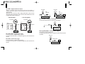
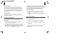
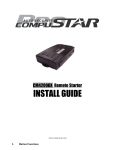
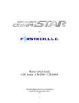
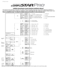
USER’S GUIDE
One-Way AM Remote R500A / Alarm Controller CM1000A
One-Way AM Remote R500A
FCC ID :O44J1WENR
This device complies with Part 15 of the FCC Rules.
Operation is subject to the following two conditions:
(1) This device may not cause harmful interference, and
(2) This device must accept any interference received, including
interference that may cause undesired operation.
CAUTION : Changes or modifications not expressly approved by
the party responsible for compliance could void the
user’s authority to operate this device.
By: Firstech, LLC.
www.compustar.com
By Firstech, LCC
www.compustar.com
2
User’s Guide
User’s Guide Table of Contents
Safety information
Page 3
Remote Description: R500A
Page 3
Remote Button Functions
Page 4
Remote Coding Procedure
Page 5
Locking and Unlocking the Doors
Page 5
Arming and Disarming System
Page 6
Trunk Release
Page 6
Panic Mode
Page 6
Valet Mode
Page 7
Optional Programmable Features
Ignition Controlled Door Locks
Page 7
Passive Locking
Page 8
Starter or Ignition Kill
Page 8
Anti Jacking Mode
Page 9
Mute Mode
Page 9
Door Open Indicator
Page 9
3
Safety Information
4
Re m ote Button Functions
Button
Servicing your vehicle or loaning it to others
Servicing your vehicle or loaning it to others When servicing the vehicle,
like changing/checking the oil, or loaning your vehicle to someone who
may not be familiar with Compustar systems, it may be best to put the
system in valet mode.
Press
Function
1
0.5 sec Lock
2
0.5 sec Unlock
3
0.5 sec Siren Chirps - on/off (while arming/disarming)
4
0.5 sec Valet Mode - on/off
Putting the system in Valet Mode will prevent them from accidentally
activating and/or triggering the Compustar alarm or operations.
Compustar systems could be frustrating to use for someone who is not
familiar with them, and who has no documentation available to reference
for instruction.
5
2.5 sec Panic, Press
6
0.5 sec Ignition Controlled Door Locks - on/off
Re m ote Description
7
0.5 sec Passive Arming - on/off
8
0.5 sec Shock Sensor - on/off
9
2.5 sec Trunk Release- on/off
10
2.5 sec Programming Menu
The R500A is a one-way AM four button remote.
or
to shut off the Siren
5
6
Remote Coding Procedure
Arming and Disarming the System
The remote must be coded to the system installed in the vehicle before it
can be operated in any way. Listed below is the remote coding
procedure, please read through the directions before beginning.
To arm the alarm, hold the
button down until the LED on the remote stops
flashing. To disarm the alarm, hold the button down until the LED on the
remote stops flashing. In either case, if the LED on the remote stops flashing
and the operation was not performed, you will need to release the button and try
again. These operations will lock and unlock the doors as well.
Step 1 : Turn the ignition ON then OFF, five times within seven seconds.
The parking lights on the vehicle should flash once.
Step 2 : Tap the
button once.
The parking lights on the vehicle should flash once.
Step 3 : Repeat step 2 for each additional remote you have.
You can only program up to three remotes.
Step 4 : Wait a few seconds.
The parking lights on the vehicle should flash twice.
If you programmed three remotes, the lights will flash twice right
Trunk Release
To release the trunk, hold the
button down until the LED on the remote
stops flashing. If the LED on the remote stops flashing and the operation was
not performed, you will need to release the button and try again.
away without waiting a few seconds.
Panic Mode
Locking and Unlocking the Doors
To lock the vehicle doors, hold the
button down until the LED on the
remote stops flashing. To unlock the doors, hold the
button down until
the LED on the remote stops flashing. In either case, if the LED on the
remote stops flashing and the operation was not performed, you will need
to release the button and try again.
Panic mode is to be activated when you are in trouble, or when you otherwise
want to call attention to your vehicle. Once panic mode is activated, the doors
will lock, the system will arm, and the siren will begin to sound. At this time the
parking lights will be flashing as well. To activate panic mode, hold the
button down for at least 2.5 seconds.
7
Valet Mode
When in Valet mode, locking and unlocking the vehicle doors will be the
only operations available through the remote, the system will not arm the
alarm. The siren will be muted at this time as well. Use Valet mode mainly
for the reasons described in the “Safety Information” section of this
manual. To activate Valet mode, tap the
and
buttons
simultaneously for a split second. Do the same again to remove the
system from Valet Mode.
Note: If you have lost or damaged the remote, you can manually enter
Valet mode by turning the ignition on then off 5 times.
You can exit Valet mode only with a remote.
OPTIONAL FEATURES/FUNCTIONS
These optional functions and features may require additional installation
and/or programming. Please see your installer for more information.
Ignition Controlled Door Locks
With this feature turned on, when the vehicle is started with the key, the
doors will lock after the vehicle has started. The doors will lock as soon as
the key has been inserted and a turned to the ON position and either 30
seconds has passed, or the brake pedal has been pressed. The doors will
then unlock when you turn the key to the OFF position. This option must
be turned on through option programming.
8
Passive Locking
With Passive Arming/Locking turned on, the system will arm and lock the
doors 30 seconds after closing the last open door. The process will go as
follows:
10 seconds after closing the last door : 1 siren chirp and 1 parking light flash.
20 seconds after closing the last door : 1 siren chirp and 1 parking light flash.
30 seconds after closing the last door : 1 siren chirp and 1 parking light flash,
at this time the system will arm, and lock the doors as well.
This process is designed to notify you that the system is about to lock the
doors in case your keys are still located in the vehicle. If this process begins,
but you don't want the doors to lock, simply open one of the doors or turn the
ignition to the ON position. The process will stop until the either the ignition is
turned off and/or the last door is closed again. It will then restart at the
beginning. To activate Passive Arming/Locking, tap the
and
buttons
simultaneously for a split second. Do the same again to deactivate Passive
Arming/Locking.
Starter or Ignition Kill
All systems come with a pre-wired starter kill relay that, when the system
is locked and armed, the relay is set to monitor the ignition. If the ignition
is turned on, the relay will trigger and sever the starter wire to keep the
vehicle from starting, even with the key.
Alternatively, the relay can be rewired to sever the ignition wire instead.
This would be optimal in two cases; manual transmission vehicles, and
for using Anti-Jacking mode.
10
9
In a manual transmission vehicle, if the ignition is powered up, the vehicle
can be compression or “bump” started without using the starter. Disabling the
ignition will keep the vehicle from starting.
Anti-Jacking Mode
To use Anti-Jacking mode, the starter kill relay must be rewired to an
ignition kill, and Anti-Jacking mode must be turned on in the programming
options. With Anti-Jacking mode, if someone pulls you out of your vehicle
while it is running and attempts to drive off with it, you can then Panic the
system by holding the
button down for at least 2.5 seconds. The system
will then sound the siren and flash the parking lights, 30 seconds later; the
system will activate the ignition kill which will disable the vehicle. This is so
you can activate Panic mode while the thief is still in range of your remote
and have enough time to get out of immediate danger before the vehicle is
disabled.
Mute Mode - Silent Arm/Disarm
When operating in mute mode, the siren on the vehicle will not sound
during normal operations such as arm/disarm, lock/unlock, etc.
The siren will still sound if the alarm or Panic mode has been triggered. To
activate Mute mode, tap the
and
buttons simultaneously for a split
second. Do the same again to deactivate Mute mode.
Door Open Indicator (Option 3)
With this option turned on, if you leave your car without shutting all of the
doors, the parking lights will flash.
Installation Guide
Installation Guide Table of Contents
Installation Tips and Recommendations
Page 11
CM1000A Wiring Diagram
Page 13
CON 1
Page 14
CON 2
Page 15
CON 3
Page 16
CON 4
Page 19
CON 5
Page 19
Antenna
Page 19
Option Menu
Page 20
Programming Menu Options
Page 21
Resetting Menu Options
Page 22
11
Installation Tips and Recommendations
1. Precautions to prevent locking yourself out
Lower the window in one or more doors before beginning installation. This
allows you to reach inside the vehicle in case you accidentally lock the keys
inside the vehicle during the course of installation. Remotes are not
programmed to the system so you will have to program them before operating
the system. See page 5 for details.
2. Use a digital multi-meter for testing circuits
Use a digital multi-meter for all wire testing in the vehicle. This should be done
on all wires even if you feel that you know exactly what they are and how they
should test. Use of a test light draws a considerable amount of current and may
damage the electrical circuit you are testing.
3.Find a good ground
One of the most important wire connections you will make is the connection to
ground. Please find a location that has a low resistance path to the ground
terminal of the battery. A poor ground will result in all kinds of future problems
in operation.
4.Make surethe installation is not, or will not,
be a driving hazard
During the installation process, try to foresee any potential hindrances,
distractions, or problems for the driver.
a. Driving hazards
. There should be no wiring around any of the pedals.
12
b. Connecting and insulating wires
. Solder all connections.
. Insulate all wires with shrink tube or electrical tape.
c. Make sure that vibration or heat will not damage or otherwise alter your
installation.
. Use zip-ties, tape or other securing devices to ensure that your wires and
components stay where you put them.
. Do not route wires or mount components near sources of extreme heat
such as exhaust manifolds.
. Do not route wires or mount components near moving parts of the
engine or vehicle.
d. User familiarity with operations.
. The operations and features of the system should be explained
thoroughly to the customer to prevent frustration due to the inability to
operate all functions.
5. Vehicle check-in and check-out.
Doing a vehicle check-in prior to installation will help identify safety
hazards that are currently present in the vehicle.
A vehicle check-in can be used to identify any present damage to the
vehicle that may be blamed on the shop or installer when the vehicle
is picked up or even at a later date.
Damage could include vehicle systems that are malfunctioning or even
not functioning at all, as well as scratches and dents.
A vehicle check-out can be used to make sure the vehicle is functioning
as well as it did when it was checked in, as well as be used as a time to
educate the customer about the various features and functions of their
new system.
13
CM1000A Wiring Diagram
14
CON 1
Red : 12v Constant Input
Constant 12-volt (+) positive power input for the control module. This wire
must be connected to a constant 12-volt (+) positive source. The proper wire
will test 12-volt (+) positive with the key in the off position, while key is in the
on position and during crank.
Violet : (+) Parking Light Output
Connect this wire to the (+) positive parking light wire generally at the parking
light switch or behind the fuse box. The proper wire will test 12-volts (+)
positive when the parking light switch is in the on position.
Brown : (+)12v Siren Output
This wire will provide a 30 second (+) positive output for the external siren.
Gray : (+)12v Trunk Output
This wire will provide a (+) positive trigger pulse. (Note: Negative trigger trunk
release will require a relay. System will unlock doors and disarm alarm prior
to trunk release.)
trunk
Solenoid
trunk Release Switch
CON1-4
Black : Chassis Ground
This wire will connect to chassis ground. This is one of the most important
connections you will make. Choose a factory grounding point or strip back the
paint before grounding. We do not recommend using the steering column.
Proper grounding is crucial to preventing future problems.
15
16
CON 2
Method 2
Positive Trigger Door Lock System (W/O Actuator)
< Circuit diagram >
< Circuit diagram during unlock output >
The lock and unlock outputs of the CM1000A
are actually two pre-wired relays that can be
configured in the three following ways listed
below. When connecting to a constant 12v+
source, you must fuse the connection.
Method 3
External Actuator
< Circuit diagram during lock output >
Method 1
Negative Trigger Door Lock
System (W/O Actuator)
< External Actuator >
CON 3
No.1 Green : (+)12v Ignition Input
This wire must be connected to the vehicles ignition to trigger remote
programming and Valet mode. The proper wire will test 0-volts with the key in
the off position, 12-volts (+)positive while the key is in the on position and 12volts (+) positive during crank.
17
18
No.2 Blue : Negative Starter Kill Output
250mA (-) negative output when armed. This wire will provide a (-)
negative output when system is locked and armed, and is pre-wired to the
starter kill relay.
(Note:This wire can also be used to trigger after-market L.E.D. kits and
other after-market accessories. Output must be diode isolated when used
to trigger after-market accessories.)
.... Starterkill Mode ...
Key Cylinder
ON
85
Starter Wire
87
86
87a
85
86
30
Starter
Door
Trigger SW
+12V
+12V
CON3-3(-) Door Trigger
CON3-4(+) Door Trigger
Ignition Wire
87
Cut
Door
Trigger SW
No.5 Violet/Black : Negative Trunk Trigger
This input will monitor when the vehicles trunk is opened.
ON
OFF
Relay
Relay
C
AC
Dome Light
START
START
C
AC
OFF
Key Cylinder
.... Anti Jacking Mode ...
Dome Light
87a
Trunk Lamp
+12V
Cut
CON 3-5
(-)Trunk Trigger Input
30
Engine
No.3 Red / Black : Negative Door Trigger
This wire monitors (-) negative trigger door-pins.
The proper wire will provide a (-) negative trigger only when the doors are
opened.
No.4 Red : Positive Door Trigger
This wire monitors (+) positive trigger door-pins.
The proper wire will provide a (+) positive trigger only when the doors are
opened.
No.6 Light Blue/White : Positive Brake Trigger
Connect this wire at the brake switch.
The proper wire will test 12-volts (+) positive only when the foot brake
is pressed.
Stop Lamp
Foot Brake S/W
+12V
CON3-6(+)Brake Trigger
19
20
No.7 Black/White : Negative Input for Optional Sensor
When installing additional sensors, use this wire as the input wire to the alarm
module for those sensors. When connecting more than one sensor to any input
wire, you must diode isolate the output wires of each sensor. Otherwise, they
could back feed into each other, causing false alarms or sensor damage.
CON 4
No. 1 Black : L.E.D. Ground
No. 2 Black / White : L.E.D. 3v Positive
Option Menu
Features
1
No. 1 Black
No. 2 White
No. 3 Red
No. 4 Yellow
: Shock Sensor Ground
: 2nd Stage Shock Sensor Input
: Shock Sensor 12v Positive
: 1st Stage Shock Sensor Input
Antenna
When installing the antenna wire, please take care to not excessively bend or
twist it. Excessive or sharp bending or severe twisting can be the cause of
inoperability or range issues.
(Optional Setting)
Door Lock/Unlock Pulse Duration
0.8 Sec
4 Sec
Anti-jacking
2
Application of Pre-wired Kill Relay
Starter Kill
3
Door Open Parking Light Indicator
Disabled
Enabled
4
30 sec Passive Relock
Disabled
Enabled
Disabled
Enabled
5 Double Pulse Unlock
CON 5
(Factory Default)
(IG-kill)
1. Door Lock/Unlock Pulse Duration
This option determines the output duration of the lock and unlock pulses
Some Vehicles do not respond to short lock/unlock pulses.
2. Application of Pre-wired Kill Relay
This option requires that the starter kill relay be installed in the ignition circuit,
rather than into the starter circuit. With this option turned on, Panic mode will
become Anti-Jacking mode. If Anti-Jacking is activated while the vehicle is
running with the key in the ignition, the siren will sound for 30 seconds.
After 30 seconds the system will break the ignition circuit, therby disabling the
vehicle. The siren will continue to play for 1 more minute. With this option
turned off, when Panic mode is activated, the system will arm, activate the
starter kill, and play the siren for 1.5 minutes.
3. Door Open Parking Light Indicator
With this option enabled, the parking lights will flash if a door is left open
while the vehicle is being armed. This serves as a warning that all of the
doors have not been closed.
21
22
4. 30 sec Passive Relock
With this option enabled, after disarming the system with the remote,
the system will relock the doors and arm the alarm after 30 seconds if a door
has not been opened. At 10 and 20 seconds after the disarm command was
given, the siren will chirp once to indicate that the alarm is about to rearm.
At 30 seconds after, the siren will chirp once, and the system will arm the
alarm. If you wish to stop this process, you must open a door within 30 seconds
of disarming the alarm.
5. Double Pulse Unlock
With this option enabled, the unlock wire will perform a double pulse every
time the unlock command is given. Some vehicles require this double pulse
to operate the locks correctly.
Programming Menu Options
You can only program one option at a time. You will have to repeat the
procedure to program additional options. Please read through the procedure
before beginning.
1.Enter programming by pressing the
button, and the
simultaneously until the parking lights flash once.
3.Wait a few seconds, and the parking lights will flash the number of times
corresponding to the option number you are about to modify. If the number of
times the lights flash does not correspond with the option you want to change,
wait a few seconds and the siren will sound, signaling that you have
exited programming mode. After the siren sounds, you can retry the
process from the beginning.
4. Immediately after the parking lights stop flashing from step 3, press:
a. The
button for the factory default setting. The parking lights will
flash once.
b. The button for the optional setting. The parking lights will flash twice.
Resetting Menu Options
If you are not sure about current programming, you can change everything to
the factory settings and start again.
1. Enter programming by pressing the
button, and the
button
simultaneously until the parking lights flash, and siren chirps, once.
button
2.Tap the
button the number of times equal to the option you would like to
change. For example, if it were the 2nd option in the menu that you would
like to change, you would tap the
button two times. The parking lights will
flash and the siren will chirp each time you tap the
button.
2. Tap the
button 3 times, waiting for a parking light flash and siren chirp
between each time.
3. The parking lights will flash, and the siren will chirp, three times, signaling
that all of the options have been reset, and that you have exited
programming mode.