1
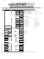
V.37 Firmware or Greater
CM4000 Alarm/Starter Control Module Installation Manual
This manual is for authorized CompuStar Pro dealers. Please thoroughly review this manual before beginning installation. If
you have any questions please contact your distributor or tech support 888-820-3690. (8:00 am to 5:00 pm Pacific Coast Time)
This is a simplified manual. The Master Installation Manual is available on www.compustar.com.
1 Red
2 Green /
White
3 Red / White
4 White
5 Violet
6 Yellow
7 Green and
Red
8 Black
CN1
CN2
1 Green /
White
3 Red / Black
5 Green
7 White /
Black
CN3
9 Black
11 Orange
13 Orange /
White
Door Trigger
Polarity
Green/White Loop
15 White
Cut=Auto Trans. Uncut=Manual
Trans.
17 Violet
(+)
(-)
Default
CN4
Key
Sense/Glow
Plug Polarity
Behavior of
CN1, Pin 2
(+)
Jumpers
(-)
( + ) Parking
Lights
Default
4(-)
3(+)
2 Data
1 Data
1 Black / White
1st Stage
(+)
4 Grey / White
3 Red
2nd Stage
2 Black / White
( - ) GWA
1 Black
( - ) Switch
( + ) Led
3 Gray
2 Gray
( - ) Led
1 Gray / Black
2: ( + ) Parking Light
4: ( + ) Accessory
6: ( + ) Starter prewired to Starter Kill Relay
8: ( - ) Ground
1: ( + ) 12v Back Up Battery
2: ( - ) Ground Back Up Battery
2 Lt Blue
1: ( - ) Parking Lt. Output – POC 1
2: ( - ) E-Brake Input
3: ( - ) Starter Output – POC 2
4: ( + ) Brake Input
5: ( - ) Ignition Output – POC 3
6: ( - ) Trunk Input
4 Lt. Blue /
White
6 Violet /
Black
8 Red / White
10 Brown /
White
12 Pink
14 Yellow /
Black
16 Gray /
Black
7: ( - ) Accessory Output – POC 4
8: ( - / + ) Door Input
9: ( - ) Status Out (GWR) – POC 5
10: ( - ) Glow Input/Key Sensing
11: ( - ) Rearm Output – POC 6
12: ( - ) Slave/Closed Loop Input
13: ( - ) Disarm Output – POC 7
14: (AC) Tach / Alternator Input
15: ( - ) Horn Output – POC 8
16: ( - ) Hood Input
18 Brown
17: ( - ) Dome Light – POC 9
18: ( + ) Siren Output
None
Future use
2 Violet /
White
3 Orange /
Black
( - ) Trunk release output
( - ) Second Unlock Output
( - ) Unlock Output
5 Blue / Black
( - ) Lock Output
None
( + ) 12v Constant Power
Black
Black / White
LED ( - )
LED ( + )
1 Black
(-)
Trunk
Release
CN5
LED
CN12
RS232
CN6
Shock
Sensor
2 Black
3: ( + ) 12v Constant and Red/White prewired to
2nd Relay
5: ( - ) When Armed prewired to Starter Kill
Relay
7: ( + ) Ignition and Red prewired to Starter Kill
Relay
1 Red
2 Black
4 Blue
Default
1: ( + ) 12v Constant
CN11
Thermistor
CN10
Optional
Sensor Input
CN9
Plug In
LED/Valet
Switch
CN7
RPS Sensor
CN8
Antenna
2 White
2nd Stage Shock
3 Red
4 Yellow
(+)
1st Stage Shock
1 Black
2 White
3 Red
(-)
Knock
(+)
4 Yellow
LED
1 Black
2 White
3 Red
(-)
(+)
TX
4 Yellow
RX
IMPORTANT: All CM4000 Control Modules need firmware updates to be 2 Way Datalink compatible. Check CompuStar.com for the latest firmware updates.
Additional Items to Install
Antenna
CompuShock
RPS
Secure Valet Switch
LED
Siren
Thermistor
Usually mounted on the front windshield. Stay at least 1 to 2 inches away from metal and try to mount below the tint stripe.
Detects impacts to the vehicle. Can be zip-tied to a wire harness or mounted with the supplied hardware.
Remote Paging Sensor is used to page the remote from the vehicle. Usually mounted in the front windshield. Can also unlock/disarm your system.
Enables the use of Secure Valet mode, mount where the customer will have convenient access.
Bright blue flashing LED used as a theft deterrent. Usually mounted to a knockout panel or surface. LED output is 3 volts.
Six tone siren usually mounted in the engine bay.
Senses the current temperature in the vehicle. This item is connected to a port on the back side of the controller and does not need programming to turn on.
Remote Programming Procedure
Before you can program the remote(s) you must complete installation. Otherwise the only wires needed to program the remote(s) are the 12v (+) constant wires (red and red/white), the
ground wire (black), and the ignition wire (green). You must have the antenna connected to the main controller. Here are the steps for remote programming:
STEP 1: Turn the key in the ignition from the Off or ACC to the On or IGN position 5 times within 7 seconds. After the 5th ignition cycle you will hear the parking light relay click. This will
happen after the 5th cycle so it is easy to miss. If you hear two relay clicks and parking light flashes, the system has just exited remote programming mode.
STEP 2: Right after the 5th cycle and hearing the first relay click:
A. 1-Way Remote: Tap the lock button on the remote for 0.5 seconds.
B. 2-Way Remote: Tap button I for 0.5 seconds. Pro 2WSSR place battery in remote.
STEP 3: After tapping the button on the remote, you will hear the parking light relay click once to indicate that it has accepted the remote. If you have other remotes to program to the
system, repeat step 2 for each remote, one after the other. Each system can accept three remotes with the exception of the P2WSSR.
Remote Programming with the Secure Valet Switch – Option 3-10 Setting III
If you install the Secure Valet Switch you must program Option 3-10 to setting III. Entering the code is now the only option to coding remotes. The default code is 3, 3. Upon entering
the code you will hear the parking light relay click. Follow the steps in the remote programming procedure above. See the section in this manual regarding Programming the Secure
Valet Switch.
Updating Control Module Software
The Research and Development Team at Firstech is constantly changing software to bring you quality product. If you are unsure which version your control module you have please
check the Dealer Support section of www.compustar.com for information. We recommend updating the control module before installation. The instructions on how to complete this
procedure are also available at www.compustar.com. Here is a list of the items needed to update your control module which are also included with the OP500 Option Programmer:
1. CM4000 Control Module
2. Secure Valet Switch
3. USB WebLink Updater
4. Y-cable (shown on www.compustar.com)
Setting the RPS (Remote Paging Sensor) Code
Basic RPS and car call functions do not require programming. To set the unlock/disarm code you must perform the following procedures:
STEP 1: Disarm/unlock the system (remote must be programmed first)
STEP 2: Turn ignition key to the “on” position and leave the driver’s door open.
STEP 3: Knock on the windshield in front of the RPS a total of 10 times (each time you knock the LED on the RPS will flash RED). The LED will begin to flash rapidly in BLUE with
successful completion of this step.
STEP 4: Enter the first digit of the desired four-digit pass code by knocking on the windshield in front of the RPS the desired number of times. For example, to enter 3, knock on the
sensor 3 times (each time you knock the LED will flash RED) then wait.
STEP 5: The LED on the RPS will confirm your first number by flashing BLUE slowly. Once the LED begins to flash rapidly in BLUE, enter your second number by repeating step 4.
STEP 6: Repeat steps 4 & 5 to enter all four numbers.
STEP 7: Turn the ignition OFF - the RPS disarm/unlock feature is now programmed. Follow steps 3 – 5 to enter your disarm/unlock code.
Programming the Secure Valet Code
The optional Secure Valet Switch prevents the alarm from being put into valet mode through cycling the ignition on/off five times. The Secure Valet Switch is more secure than traditional
toggle / valet switches because it requires a two-digit code. (Default code is 3, 3) IMPORTANT: The first two-digits of the RPS unlock/disarm pass code will be the default pass code for
the secure valet – you do not need to program them independently. If you are not using the RPS unlock, following the below procedures to program your secure valet pass code:
STEP 1: Turn on Option 3-10-III. (Dealer programmed option)
STEP 2: Disarm/unlock the system and turn ignition key to the “on” position and leave the driver’s door open.
STEP 3: Hold down the valet switch for 1.5 seconds. The LED on the valet switch will begin to flash rapidly in BLUE with successful completion of this step.
STEP 4: Enter the first digit of the desired two-digit pass code by depressing the switch the number of times that coordinates with the desired first number. For example, to enter 3,
depress the switch 3 times, then wait.
STEP 5: The LED will confirm the first number by flashing BLUE slowly. Once the LED begins to flash rapidly, enter your second number by repeating step 4.
STEP 6: Turn the ignition off - the Secure Valet Switch is now programmed. Follow steps 3 – 5 to enter your Secure Valet code.
Setting Auxiliary Outputs on Connector 3 – You Must Have the OP500 Option Programmer
To set auxiliary outputs on the CompuStar Pro control modules involves the new Programmable Output Connector wires (POCs). You must choose two odd pin wires on the black 18 pin
connector that you are not using. For example choose POC 8 and 9.
STEP 1: Plug in OP500 and use the Right or Left Arrow Button to scroll through the menu to POC 8 and POC 9 on LCD Line 1.
STEP 2: Use the Up or Down Arrow Button to change the lower number on LCD Line 2 to 10 – Auxiliary 1 or 11- Auxiliary 2.
STEP 3: Scroll up the menu to Option 4-01 and 4-02 and set the options. Please see the Option Table for details.
STEP 4: The Pro control modules have a secure auxiliary option 4-05. This requires you to tap button 4 before you tap button 2 for Aux 1 or button 3 for Aux 2. On 1-Way remotes you
must hold the Trunk and Key/Start buttons for 2.5 seconds then tap the Trunk button for Aux 1 or the Key/Start button for Aux 2.
STEP 5: If you need to change the time settings of the outputs go to AU1 or AU2 on the OP500. LCD Line 2 is the timed output.
STEP 6: Hold the “W” Write button for 3 seconds to set all the options.
Option Settings You Need OP500 For:
Option 2-03 Diesel Timer is default to 10 seconds. To change the time you need the OP500. LCD Line 1 will read DISL after Menu 4.
Option 3-11/3-12 Auxiliary Settings. To change settings with the auxiliary settings you must first set POC9 to 10 and connect to the White wire on the auxiliary settings. The
Auxiliaries 1 through 7 can only be set with the OP500
POC 1 through 9 can only be set with the OP500. They can be changed from default – 0 to anything. Please see the Option Table for details.
Option Programming Tables
Option Programming with Remotes and OP500, RPS Unlock and Secure Valet are programmable ONLY when system is Unlocked/Disarmed.
OPTION GROUP 1
Feature
Default Setting - I
Optional Setting - II
Optional Setting - III
Optional Setting - IV
1-01
Unlock before, Lock after, starting
Off
On
Lock After Remote Start
Only
Lock After Shutdown
Only
1-02
Lock / Unlock pulse duration
0.8 sec
2.5 sec
0.125 sec
3.5 sec
1-03
Driver's priority unlock
Off
On
1-04
Double pulse unlock
Off
On
1-05
Rearm Output
After Start Shutdown
and First Lock
After Start Shutdown
and Every Lock
After Start Only
After Shutdown Only
1-06
Reservation Lock
(Manual transmissions)
Locks When
Reservation Mode is Set
Does Not Lock When
Reservation is Set
Reservation Sets 10
Seconds After the Last
Door is Closed
1-07
Unlock / Disarm With Trunk Release
1-08
Locking while in Passive Arming
Unlock, Factory Disarm,
and Trunk Release
Passive locking with
Passive Arming
Factory Disarm, Trunk
Release Only
No Passive Locking with
Passive Arming
Trunk Release Only
1-09
Ignition controlled door locks
Off
On
RPM Locks (Tach
Sensing Mode Only)
1-10
Auto Relock (If a door is not opened
within this amount of time)
Off
30 sec
60 sec
5 min
Acc Pulse - same timing
as disarm pulse
Ignition and Acc Pulse same timing as disarm
pulse
Optional Setting - IV
Ignition / Accessory Out Upon Unlock
Off
Ignition Pulse - same
timing as disarm pulse
1-13
Double Pulse Disarm Input
Single Pulse
Double Pulse
1-14
Auto Lock Mode (2 Way International
Remotes)
Off
On
Feature
Default Setting - I
Optional Setting - II
Optional Setting - III
Tach Sensing Method
Optimal Tach Method
Previous Tach Method
Low Threshold Tach
Method
1Min
4 Min
Double Pulse
Triple Pulse
1-11
OPTION GROUP 2
2-01
2-02
Turbo Timer
Off
2 Min
2-03
Diesel Timer
Wire
3~99sec (10sec Default)
2-04
Trigger Start
Off
Single Pulse
2-05
Cold Start with Thermistor Assembly
Off
On
2-06
Timer Start, or, Minimum Interval
Between Cold Starts
3 Hour (4 minute
runtime, double for
Diesel)
1.5 Hour(4 minute
runtime, double for
Diesel)
Reservation
(Runtime set by 2-7)
2 Way LCD Remotes
Only
24 Hour Repeat with
Cold Starting of 2-8
(Runtime set by 2-7) 2
Way LCD Only
2-07
Remote Start Runtime
15 Min
25 Min
45 Min
3 Min
2-08
Temperature of Cold Starting
-10° C / 14° F
-20° C / -4° F
-5° C / 23° F
-15° C / 5° F
2-09
Temperature of Hot Starting
25° C / 77° F
30° C / 86° F
35° C / 95° F
40° C / 104° F
No Connection – No
Tach Sensing
(Not for Manual
Transmissions)
No Connection – 1.5
Second Crank
(Not for Manual
Transmissions. V.33 or
greater)
+0.6 Seconds to Crank
Time
(No Tach Sensing Only)
(-)0.2 Second Crank
Time
Optional Setting - IV
2-10
Engine Sensing
Tach
Alternator
2-11
Turbo, Remote Start Runtime
Extension w/ #1 for 2 seconds
No
Yes
2-12
Crank Time
Standard
+0.2 Seconds to Crank
Time
Feature
Default Setting - I
Optional Setting - II
Optional Setting - III
3-01
Parking lights While Remote Started
Constant Output
Flashing Output
Off
3-02
Dome Light output
Off
Factory Rearm
45 sec
Factory Rearm + 45 Sec
3-03
Dome Light Delay
Off
5 sec
3-04
Starter-Kill Relay
Anti-Grind + Starter Kill
Anti-Grind
3-05
Anti-Jacking
Starter-kill
Ignition-Kill
(no Anti-Grind)
3-07
Siren Duration (Upon Alarm Trigger)
OPTION GROUP 3
3-09
Horn Output When Alarm Is Triggered
3-10
Valet
45 sec
Auto
Anti-Grind +
Passive Starter Kill
Auto kill
(Auto-door locks Off)
International Remotes
w/ AUTO Function Only
Auto kill
(Auto-door locks On)
International Remotes
w/ AUTO Function Only
Chirps for 20 seconds
30 sec
60 sec
120 Sec
Pulsed Output
(Horn)
Key 5 times, or Remote
(I+III) while Ignition is On
Constant Output
(Secondary Siren)
Key 5 times or Remote
(I+III)
Secure Valet
(Default code 3,3)
3-11
Auxiliary settings Mode
Disabled
Enabled
3-12
Auxiliary settings With Passive Arming
No Passive Arming
Passive Arming
OPTION GROUP 4
Feature
Default Setting - I
Optional Setting - II
Optional Setting - III
4-01
Aux 1 output
0.5sec
Latch
20 sec
Optional Setting - IV
Program
4-02
Aux 2 output
0.5sec
Latch
60 sec
Program
4-03
Aux 1 output Control
By Remote
Arm
Disarm
Panic
4-04
Aux 2 output Control
By Remote
Arm
Disarm
Panic
4-05
Secure Aux Output (1 and 2 Only)
On
Off
4-06
Auxiliary Input 1 – Green CN
Prewarn
Trigger
4-07
Auxiliary Input 2 – Green CN
Trigger
Prewarn
(-)Arm
4-08
Extended Accessory After Ign Shutoff
Off
10 sec
30 sec
4-09
Key Sense or Glow Plug input
Glow Plug Input
Key Sense Input
4-10
Trigger Start or Closed Loop
Alarm Trigger Input
Trigger Start input
Closed Loop
System Input
Feature
(-)Disarm
Until Door Open
(1 min max)
SPECIAL OPTION GROUP 1
Setting Value [seconds]
1
Diesel timer - DISL
3 ~ 99
2
AUX1 output time
1 ~ 100
3
AUX2 output time
1 ~ 100
4
AUX3 output time
1 ~ 100
5
AUX4 output time
1 ~ 100
6
AUX5 output time
1 ~ 100
7
AUX6 output time
1 ~ 100
8
AUX7 output time
1 ~ 100
SPECIAL OPTION GROUP 2
Feature
Setting Value
Programmable Output Connector
0 - Default Setting
POC #1
(-) 2nd Parking Light
(Green/White)
2
POC #2
(-) 2nd Start (Red/Black)
3
POC #3
(-) 2nd Ignition (Green)
4
POC #4
(-) 2nd Accessory
(White/Black)
5
POC #5
(-) Status/GWR (Black)
6
POC #6
(-) Rearm Wire (Orange)
Aux1 Out - [10] Aux2 Out - [11] Defrost - [17]
7
POC #7
(-) Disarm Wire
(Orange/White)
GWA - [18] Status 2 For Manual Trans. - [19]
8
POC #8
(-) Horn (White)
9
POC #9
(-) Dome Light (Violet)
1
1~19 – Optional Settings
2nd Light - [1] 2nd Start - [2]
2nd Ignition - [3]
2nd Acc - [4] Status Out - [5] Rearm Out - [6]
Disarm Out - [7] Horn Out - [8] Dome Light - [9]
Common Option Menu Descriptions
1-01 Unlock before, Lock after remote starting - Doors will unlock to remote start and then relock once started. This is to disarm factory alarms on certain vehicles.
1-03 Driver’s priority unlock - The driver’s door must be isolated from the other doors. Use the Orange/Black CN4 as your negative 2nd Unlock output.
1-04 Double pulse unlock - Sends two negative (-) pulses on the blue unlock wire.
1-06 Reservation Lock (Manual Transmission) - Setting 1 allows the doors to lock when setting reservation. Setting 2 does NOT allow the doors to lock when setting reservation.
Setting 3 gives 10 seconds before setting reservation mode after closing the last door to allow the user to open another door.
1-09 Ignition controlled door locks – Default setting locks doors when foot on foot brake. Unlocks doors when key turned off or when e-brake set on manual transmissions. Tach or
alternator sensing mode must be used for this feature. You must also turn this feature on through the remote by tapping I + IV (2 Way remotes) or Lock + Key (1 Way remotes)
2-01 Tach Sensing Method – This option changes the method which is used to read tach on different vehicles. It adjusts for situations when there may be over cranking when remote
starting. This option can also be adjusted based on option 2-12 – Crank Time. Please see tech update from April 2008 on www.compustar.com for more info.
2-02 Turbo Timer - The e-brake must be connected to the control module. Available times are 1, 2, and 3 minutes. You must also turn on this feature through the remote by tapping
buttons III + IV.
2-03 Diesel Timer - Without setting this option you must find the vehicle’s wait to start wire. The default time for Setting 2 is 10 seconds. This can be increased or decreased only
with the Option Programmer OP500.
2-04 Trigger start - This option allows the control module to be used as a slave unit. This option determines whether the slave start wire on CN3 requires a single or double pulse to
activate the remote start. This can be used on vehicles where the user would like to keep the factory remote.
2-05 Cold Start with Thermistor Assembly - This option turns on the cold/hot starting features. This option works in conjunction with 2-6, 2-8 and 2-9. The thermistor must be plugged
into the controller/brain.
2-06 Timer Start, or, Minimum Interval Between Cold Starts - This option dictates the time interval when vehicle will remote start or check temperature and remote start.
Default 1: Will start every 3 hours until the vehicle is remote started or started by key – for 4 minutes.
Option 2: Will start every 1.5 hours until the vehicle is remote started or started by key – four 4 minutes.
Option 3: Will start at the time specified on the 2 way remote one time for the duration set by Option 2-7.
Option 4: Will start at the specified time on the remote every 24 hours if the temperature falls below as set under 2-8. For example, if you want your car starts everyday 7 am in
the morning for 25 minutes when the temperature of the inside of the vehicle falls below 32°F, you need to set up:
1)
2)
3)
4)
5)
6)
Option 2-5 (Cold Start) turned on,
Option 2-6-IV (24 hr. repeat) turned on,
Option 2-7-II (25 min run-time) turned on,
Option 2-8-IV (Temp 32°F) turned on,
Set the reservation time at 7 am (see User’s guide)
Turn on Timer Mode of the 2 way LCD remotes (see User’s Guide)
2-10 Setting Tach/Alternator/No Tach Sensing/1.5 Second Crank - There are four modes for starting the vehicle. IMPORTANT: For manual transmissions you MUST use tach or
alternator sensing. The four are listed below:
1) Tachometer Wire Sensing – No Tach Learning Button on Pro Series. To learn tach press and hold the foot brake. While holding the foot brake hold the remote start button for
2.5 seconds. Tach wires can be usually be found on the coil pack of the engine or as the odd colored wire on any of the injectors.
2) Alternator Wire Sensing – This mode requires connection to stator wire on the alternator. The wire tests 0 volts DC while the vehicle is off, 1-5 volts while the ignition is on,
and a minimum of 12-14 volts while the vehicle is running.
3) No Tach Sensing – No tach sensing is an alternative engine sensing mode. No tach sensing does not require a connection to the vehicle other than the main ignition harness.
4) 1.5 Second Crank (V.33 or greater) – This option creates a 1.5 second crank output on the yellow starter wire. Should only be used for vehicles with built in anti-grind.
2-12 Crank Time – This option changes the crank time when reading tach on different vehicles. It adjusts for situations when there may be under cranking when remote starting. Please
see tech update from April 2008 on www.compustar.com for more info.
3-04 Starter-Kill relay - In the default setting, the relay will act as an anti-grind and starter-kill circuit. On setting 2, the relay will act as anti grind only.. Setting 3 is the same as 2, but a
passive starter-kill is activated 45 seconds after the vehicle is turned off or disarmed.
3-05 Anti-Jacking - This option requires the starter kill relay to be installed in the ignition circuit rather than into the starter circuit. With this option set to option 2, Panic Mode becomes
Anti-Jacking Mode. If Anti-Jacking is activated while the vehicle is running with the key in the ignition, the siren will sound for 30 seconds then the system will disconnect the ignition,
thereby disabling the vehicle. The siren will continue to sound for 1 more minute.
3-09 Horn Output When Alarm is Triggered - This option changes the output on the horn wire. On default setting the horn output will pulse when alarm is triggered. Setting 2 the horn
wire becomes a constant output when triggered. This output on the wire only pulses or holds ground (-).
3-10 Valet - This option changes the way you put the system into valet mode. On default setting you can either cycle the ignition 5 times with the key or turn the ignition on and tap
buttons I+III. Setting 2 you can either cycle the ignition 5 times with the key or tap buttons 1 + 3. Setting 3 turns the Secure Valet Switch on. See Programming the Secure Valet Section
above.
3-11 Auxiliary Settings Mode - This option requires the programming of auxiliary settings. If you need more than 2 of the supplied auxiliary outputs, you can use the POC options with
the OP500. With this option turned on, the Aux 2 wire from the system becomes non functional and the Aux 1 wire becomes the data wire that communicates with the auxiliary settings.
4-01 Aux 1 output - This option changes the behavior of the output on Aux 1. If you want to set a specific time change this option to Setting 4.
4-02 Aux 2 output - This option changes the behavior of the output on Aux 2. If you want to set a specific time change this option to Setting 4.
4-05 Secure Auxiliary Output (Aux 1 and 2 only) - With this option on the default setting you must first tap button 4 on the remote and then tap either button 2 or 3 to activate Aux 1
or Aux 2. This is to prevent accidental triggering of Aux 1 or 2 if they are hooked up to door poppers or window modules. On optional setting 2, this turns the secure aux off.
4-06 Auxiliary Input 1 - This option changes the input behavior of the pre-warn wire on the Aux Input Sensor (green plug). The default setting is the Prewarn when it sees a ground (-)
trigger. Setting 2 changes the input to an instant trigger. Setting 3 changes the wire into a ground (-) disarm input. That can be used as an input when using the control module as a
slave unit.
4-07 Auxiliary Input 2 - This option changes the input behavior of the pre-warn wire on the Aux Input Sensor (green plug). The default setting is the Instant trigger when it sees a
ground (-) trigger. Setting 2 changes the input to a Prewarn. Setting 3 changes the wire into a ground (-) arm input. That can be used as an input when using the control module as a
slave unit.
4-09 Key Sense or Glow Plug Input - Default setting sets the wire as a glow plug input wire. Setting 2 changes the wire into a key sense input. The key sense input is used to prevent
setting reservation (manual transmission) and passive arming while the key is still in the ignition. The dome light supervision will stop when the key is inserted in the ignition.
4-10 Trigger Start or Closed Loop System Input - Default setting is the trigger start when using the control module as a slave unit. Setting 2 changes the wire into a closed loop
system. The wire becomes an instant trigger if the wire is separated from ground. (-) This can be used for headlights housings or connected to a tow hitch.
Special Option Group 1 - This option group controls the Diesel Timer and Auxiliaries 1 though 7. Aux 3 through 7 are only available with the Auxiliary settings. The Diesel Timer can
only be set for 3 to 99 seconds. Aux 1 through 7 can be set from 1 to 100 seconds. IMPORTANT: This option group can only be accessed with the OP500 Option Programmer.
Special Option Group 2 - This option group controls the Programmable Output Connectors (POCs). The POCs are located on CN3 (odd numbered wires). IMPORTANT: This option
group can only be accessed with the OP500 Option Programmer. The default setting each option is 0. You can set each POC to 1-12. This changes the function of the POCs. Please
see the option menu and wiring guide for details of each POC.
How to Change Options with OP500 and Remotes
The options can be set using the OP500 Option Programmer, 1 Way remote, 2 Way remote, or the antenna button on Canadian ANT-1WAM or ANT-1WSH. Firstech
recommends using an OP500 Option Programmer since not all options are accessible with the remotes or antenna buttons.
Option Programming Using the OP500 Option Programmer
The OP500 can be used to program any available option. You must disarm the system before using. You no longer need to program the remotes before using (V.36.2 or greater). It is
required to program options in Special Option Groups 1 and 2. IMPORTANT: You need to update your OP500 to read options on Version 37 or greater modules.
STEP 1: Using the blue connector on the top of the OP500, connect it to the control module via the antenna wire. (Use the included extension cable if necessary.) Once connected,
the OP500 will power up as long as the main ignition harness to the controller has been connected properly.
STEP 2: To change the option number you wish to program, use the left and right arrow keys on the OP500. It will scroll through the options available in menu 1 and then move
to menu 2, then 3 and 4. Use the up and down arrow buttons on the OP500 to adjust the option settings; “1” is the default setting, and “2”, “3”, and “4” are the optional settings.
At the end of menu 4, if diesel mode or auxiliary settings functions were enabled – or if any of the auxiliary outputs were set to “Program”, the duration of these settings
can now be adjusted.
Following the auxiliary and diesel settings (if selected), the POC options will be displayed on the OP500. The POCs can be set between 0 (default) and 19.
STEP 3: When finished with the adjustment of the various option settings, press and hold the “W” (Write) button until the OP-500 chirps, which is approximately 2.5 seconds.
This will write the settings to the control module. Wait until the module displays “Success” before disconnecting it from the antenna cable.
To reset the options, hold the “R” (reset) button and “W” (write) button for 2.5 seconds. To write the reset, hold the “W” button until the OP-500 chirps, which is approximately 2.5 seconds.
Option Programming Using a Remote
Using a remote is a timed process so read this section in its entirety before beginning. IMPORTANT: Special Option Groups cannot be programmed with a remote – the OP500 must
be used. If at any time during the process you hear a long siren or horn sound the system kicked you out of programming mode.
STEP 1: Select the option menu that contains the desired programming option.
To select a menu, use the following button combinations:
I+II for 2.5 sec. then I+II for 2.5 sec.
I+II for 2.5 sec. then I+IV for 2.5 sec.
I+IV for 2.5 sec. then I+II for 2.5 sec.
I+IV for 2.5 sec. then I+IV for 2.5 sec.
Menu 1
Menu 2
Menu 3
Menu 4
*Buttons I, II, III, IV correspond to I = Lock, 2 = Unlock, 3 = Trunk, 4 = Start on 1 Way remotes
STEP 2: After entering the option menu that contains the desired option, tap button (IV) on two-way remotes for .5 seconds and buttons (Trunk + Start) on one-way remotes
for 2.5 seconds the number of times equal to the option number. Wait for a parking light flash and siren chirp between each button press. After selecting the desired option number,
the system will confirm which option you have selected by the number of siren chirps and parking light flashes.
STEP 3: Once the system is finished confirming the option number, set the option to the desired setting by tapping buttons I, II, III, or IV. To set options with the one-way remote the
button configuration is different. Tap the Lock Button for Setting 1, Tap the Unlock Button for Setting 2, Tap the Key Button for Setting 3, and Hold the Trunk and Key Buttons for Setting
4.
Resetting to Factory Defaults: To reset the options in a particular menu group, enter the menu by following STEP 1, then tap button III for 0.5 sec, three times. Wait for the siren to chip
and parking lights to flash between each tap. After the third tap, the option menu will reset and the siren will chirp three times. This must be done for each option group that needs to
be reset.
Option Programming Using the 1-Way Antenna Button
Programming the main controller option using an antenna is a timed process so you should read the instructions entirely before beginning.
STEP 1: Turn vehicle’s ignition to the on position.
STEP 2: Selecting the Option Menu - Select the option menu that contains the option you would like to adjust. Be aware, the special option groups are not available when programming
options with an antenna. To select a menu, use the following button combinations:
Hold antenna button until you hear/see 1 chirp/parking light flash.
Hold antenna button until you hear/see 2 chirps/parking light flashes.
Hold antenna button until you hear/see 3 chirps/parking light flashes.
Hold antenna button until you hear/see 4 chirps/parking light flashes.
Menu 1
Menu 2
Menu 3
Menu 4
STEP 3: Selecting the Specific Option - After entering the option menu that contains the option you wish to change, tap the antenna button the number of times equal to the option
number you wish to change. A few seconds after you have stopped selecting an option, the system will confirm which option you have selected by the number of siren chirps and parking
light flashes.
STEP 4: Setting the Option - After the system is finished confirming the option number, set the option to your desired setting by tapping the antenna button 1,2,3, or 4 times.
Resetting to Factory Defaults: To reset the options in a menu, enter the menu as if you were going to program an option then hold the antenna button for three seconds. The option
menu will reset and the siren will chirp three times. The options in the other three menus will remain set.
Quick Troubleshooting
Remote Start Error Codes
Number of Parking
Light Flashes
1
2
3
4
5
6
7
8
Remote Start Error
Motor running | or | must program tach before 1st remote start
Key in ignition on position | or | foot brake on
Door open (manual transmission only)
Trunk open
Foot brake on
Hood open
Reservation off (manual transmission only)
Tach or no tach sensing failure
*Pro 2 Way remotes will display the error number “Strt Er##” on the
LCD.
If the remote start fails to start the vehicle, the parking lights will flash three
times immediately. Following those three flashes the parking lights will flash
again corresponding to the error table
Relay Diagrams For Connector 1
Green/White Loop (CM4000 and CM4200DX Models)
This loop wire determines the transmission setting. The default position (uncut loop) is for manual transmissions. When the loop is cut, the system will be ready for automatic
transmissions. In the default (manual transmission) mode, the system must be set up in Reservation mode prior to the vehicle being able to remote start. IMPORTANT: All warranties
or claims are void if a controller with a cut loop is installed on a vehicle with a manual transmission.
Tach Learning
When you go to learn the tach by holding the foot brake and holding the remote start button for 2.5 seconds on the remote. If you see three parking light flashes followed by a certain
amount then there is an error. This table shows you what the second set of flashes represent.
Number of Parking Light Flashes
1
2
3
Tach Error
Option 2-10 is not in default setting 1
Key is in the off position
Bad tach signal. Find a different wire.
Alarm LED Diagnostics
When the alarm is triggered the LED on the RPS (if installed), Secure Valet (if installed) and the LED (if installed) will flash a certain amount of times as shown in the table below. This is
intended for users with 1 Way remotes.
Priority
Trigger
LED Flash Diagnostic
1
2
3
4
Door/Hood/Trunk/Ign Triggered
2nd Shock Triggered
2nd Auxiliary Input Triggered
Panic with remote
2 flashes, rest, then repeat
3 flashes, rest, then repeat
4 flashes, rest, then repeat
5 flashes, rest, then repeat
Software Version Diagnostics
This is a new feature added with V.33 or newer software. When you turn the ignition on and hold buttons I + IV on the 2 Way remotes or Lock + Key on the 1 Way remotes the parking
lights and LED will flash to show which version software is on the control module. Version 33 will show up as 2 parking light flashes.
Frequently Asked Questions
I have everything hooked up and the system will not respond.
A: The remotes need to be programmed. Review the “Remote Programming Procedure” section of this manual.
I am trying to program the control module with the OP500 Option Programmer and it flashes “ER 02” when I plug it in to the antenna cable. What should I do?
A: Make sure that the system is not locked/armed. The last thing to check is the antenna cable or antenna extension cable – make sure this is not damaged. If you need to, try another
cable. When the OP500 is working properly, it will read “success good.”
Where do the blue and purple wires off the extra relay go on the CM4000/CM4200DX?
A: This is a pre-wired positive output, negative trigger relay. Use the secondary ignition, starter, and accessory outputs from CN 3 to give a negative trigger to the purple wire. This will
determine the12V positive (+) output of the blue wire, which you can then connect to your secondary ignition, starter, or accessory wire.
I need a ground when armed wire for i.e. window modules, does control module have one?
A: You can use the starter output on CN1 that goes to the starter kill relay. You must cut this wire and place a diode in line so that when the ignition on the other side of the relay goes to
ground, it won’t back feed to your accessory. Install the stripe side of the diode facing the control module.
I have the Pro 2WSSR remote and antenna and am trying to upgrade the system, what do I need/do?
A: Make sure you have the 4 pin to 6 pin antenna cable and that you have the most current software on the control module. This should be Version 28 or greater.
Drive Lock (Ignition Controlled Door Locks) are programmed and tach set but still do not function. What is wrong?
A: Once you program Option 1-09 you must also turn the option on with the remote. Buttons I + IV 2 Way remote, Lock + Key buttons 1 Way remotes.
Technical Support Contacts
Firstech technical support is reserved for authorized dealers only.
Monday - Friday
888-820-3690
(8:00 am – 5:00 pm Pacific Coast Time)
Email
[email protected]
Web
http://www.compustar.com click on “dealer support”
Wire Diagrams
Click on the “Installogy Access Client” link found on your desktop. If you are a qualified dealer
and unable to access this site, call your sales representative or the number above.
www.compustar.com
Toll Free: 888-820-3690
th
21911 68 Ave S
Kent, WA 98032