1
Giga-tronics 2400 and 2500 Series Microwave Signal Generators
2400 and 2500 Series
Microwave Signal Generators
Programming Manual
Programming Manual, Part Number 34783, Rev A, July 2009
Giga-tronics 2400 and 2500 Series Microwave Signal Generators
All technical data and specifications in this publication are subject to change without prior notice and do
not represent a commitment on the part of Giga-tronics, Incorporated.
© 2009 Giga-tronics Incorporated. All rights reserved. Printed in the U.S.A.
Warranty
Giga-tronics 2400/2500 Series instruments are warranted
against defective materials and workmanship for one year from
date of shipment. Giga-tronics will at its option repair or replace
products that are proven defective during the warranty period.
This warranty DOES NOT cover damage resulting from improper
use, nor workmanship other than Giga-tronics service. There is
no implied warranty of fitness for a particular purpose, nor is
Giga-tronics liable for any consequential damages. Specification
and price change privileges are reserved by Giga-tronics.
CONTACT INFORMATION
Giga-tronics, Incorporated
4650 Norris Canyon Road
San Ramon, California 94583
Telephone:
800.726.4442 (only within the United States)
925.328.4650
Fax:
925.328.4700
On the Internet:
www.gigatronics.com
Programming Manual, Part Number 34783, Rev A, July 2009
Giga-tronics 2400 and 2500 Series Microwave Signal Generators
Regulatory Compliance Information
This product complies with the essential requirements of the following applicable European
Directives, and carries the CE mark accordingly.
89/336/EEC and 73/23/EEC
EN61010-1 (1993)
EN61326-1 (1997)
EMC Directive and Low Voltage Directive
Electrical Safety
EMC – Emissions and Immunity
Manufacturer’s Name:
Giga-tronics, Incorporated
Manufacturer’s Address
4650 Norris Canyon Road
San Ramon, California 94583
U.S.A.
Type of Equipment:
Microwave Signal Generator
Model Series Number
2400 Series
2500 Series
Model Numbers:
2408C, 2420C, 2426C,
2440C
2508B, 2520B, 2526B,
2540B, 2550B
Declaration of Conformity on file. Contact Giga-tronics at the following;
Giga-tronics, Incorporated
4650 Norris Canyon Road
San Ramon, California 94583
Telephone:
800.726.4442 (only within the United States)
925.328.4650
Fax:
925.328.4700
Programming Manual, Part Number 34783, Rev A, July 2009
Giga-tronics 2400 and 2500 Series Microwave Signal Generators
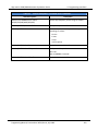
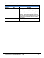
Record of changes to this Manual
Use the table below to maintain a permanent record of changes to this document. Replacement pages
will be issued as a TPCI (Technical Publication Change Instruction), and will be inserted at the front of
the binder. Remove the corresponding old pages, insert the new pages, and record the changes here. Do
the same thing with TCPI pages that are issued after you have received this manual.
TPCI Number
TPCI Issue Date
Date Entered
Comments
Programming Manual, Part Number 34783, Rev A, July 2009
Giga-tronics 2400 and 2500 Series Microwave Signal Generators
Table of Contents
Table of Contents........................................................................................................................................... i
Chapter 1.
Safety .................................................................................................................................... 1
1.1
Unsafe Operating Conditions........................................................................................................ 1
1.2
Safety Warnings Used in This Manual .......................................................................................... 1
1.2.1
Personal Safety Alert............................................................................................................. 1
1.2.2
Equipment Safety Alert......................................................................................................... 1
1.2.3
Notes..................................................................................................................................... 1
Chapter 2.
Introduction .......................................................................................................................... 3
2.1
Overview ....................................................................................................................................... 3
2.2
Physical Description of the 2400/2500 ......................................................................................... 4
Chapter 3.
Hardware Interfaces ............................................................................................................. 5
3.1
Introduction .................................................................................................................................. 5
3.2
Configure the 2400/2500 Hardware Interface ............................................................................. 6
3.2.1
Using the Included USB Cable ............................................................................................... 6
3.2.2
Assign a GPIB Address to the 2400/2500.............................................................................. 6
3.2.3
Configure the Computer’s RS-232 for Remote Operation.................................................... 6
3.2.4
Configure the 2400/2500 Ethernet Connection ................................................................... 7
Chapter 4.
Programming Interfaces ....................................................................................................... 9
4.1
Introduction .................................................................................................................................. 9
4.2
Select the Remote Programming Language.................................................................................. 9
4.3
Dynamic Link Library (DLL)..........................................................................................................10
4.3.1
Adding the DLL to Programming Projects...........................................................................10
4.3.2
Programming Examples Using the DLL ...............................................................................11
4.3.3
DLL Functions ......................................................................................................................17
4.4
SCPI Command Set......................................................................................................................96
4.4.1
SCPI Command Format .......................................................................................................96
4.4.2
SCPI Commands ..................................................................................................................97
4.5
IEEE 488.2 Common Commands...............................................................................................120
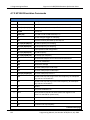
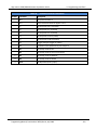
4.6
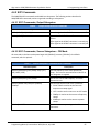
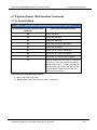
GT-12000 Native Commands ....................................................................................................122
4.6.1
GT-12000 Native Commands: CW and System .................................................................122
4.6.2
GT-12000 Native Commands: List Mode ..........................................................................123
4.6.3
GT-12000 Native Commands: Amplitude Modulation .....................................................125
4.6.4
GT-12000 Native Commands: Frequency Modulation .....................................................126
4.6.5
GT-12000 Native Commands: Phase Modulation.............................................................127
4.6.6
GT-12000 Native Commands: Pulse Modulation..............................................................128
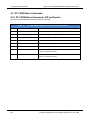
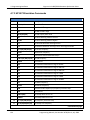
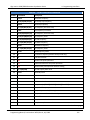
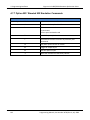
4.7
Emulation ..................................................................................................................................129
4.7.1
HP 834X Emulation Commands ........................................................................................129
Programming Manual, Part Number 34783, Rev A, July 2009
i
Giga-tronics 2400 and 2500 Series Microwave Signal Generators
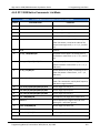
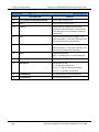
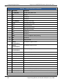
4.7.2
HP 8663 Emulation Commands ........................................................................................132
4.7.3
HP 8673 Emulation Commands ........................................................................................134
4.7.4
HP 8360 Emulation Commands ........................................................................................138
4.7.5
HP 8370 Emulation Commands ........................................................................................139
4.7.6
GT900 Emulation Commands ...........................................................................................140
4.7.7
Option 55F: Wavetek 90X Emulation Commands.............................................................142
4.7.8
Systron Donner 16XX Emulation Commands....................................................................143
Chapter 5.
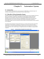
Automation Xpress............................................................................................................149
5.1
Introduction ..............................................................................................................................149
5.1.1
Benefits of Using Automation Xpress ...............................................................................149
5.2
Install Automation Xpress.........................................................................................................150
5.3
Start Automation Xpress...........................................................................................................152
5.4
Automation Xpress GUI Description .........................................................................................154
5.4.1
Tool Bar .............................................................................................................................155
5.4.2
Indicators and RF Button...................................................................................................165
5.5
Auto Programmer .....................................................................................................................167
5.5.1
Introduction ......................................................................................................................167
5.5.2
Auto Programmer Examples .............................................................................................168
Chapter 6.
Status Register System......................................................................................................171
6.1
Introduction ..............................................................................................................................171
6.2
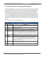
Status Byte and Service Request Enable Registers ...................................................................173
6.3
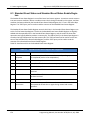
Standard Event Status and Standard Event Status Enable Registers........................................174
6.4
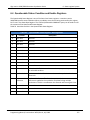
Questionable Status Condition and Enable Registers...............................................................175
Chapter 7.
2400/2500 Specific Commands ........................................................................................177
Chapter 8.
List Mode Operation .........................................................................................................179
Chapter 9.
LabVIEW Drivers................................................................................................................181
9.1
Overview ...................................................................................................................................181
9.2
LabVIEW Drivers........................................................................................................................183
9.2.1
LabVIEW Drivers for DLL Functions...................................................................................183
9.2.2
Non-DLL LabVIEW Drivers .................................................................................................187
Appendix A. Remote Error Messages....................................................................................................189
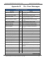
Appendix B. DLL Error Messages...........................................................................................................193
Appendix C. FM Sensitivity/Deviation RangeTable ...............................................................................197
ii
Programming Manual, Part Number 34783, Rev A, July 2009
Giga-tronics 2400 and 2500 Series Microwave Signal Generators
Chapter 1.
1. Safety
Safety
1.1 Unsafe Operating Conditions
If you notice any of the following conditions while operating electronics equipment, IMMEDIATELY
de-energize the equipment.
•
The instrument fails to operate normally, or operates erratically.
•
The power cable, receptacle, or plug on the instrument is damaged
•
The instrument causes electrical shock or operates at abnormally high temperature.
•
A liquid or foreign substance falls into the instrument
•
The instrument generates an abnormal sound, smell, smoke, or sparking light.
If any of the above conditions occurs, contact Giga-tronics to get the instrument repaired.
!
WARNING
Continuing to operate the instrument with any of the above conditions could
cause death or serious damage to the instrument and any equipment connected to it.
1.2 Safety Warnings Used in This Manual
1.2.1 Personal Safety Alert
!
WARNING
WARNING: Indicates a hazardous situation which, if not avoided, could result in
death or serious injury.
1.2.2 Equipment Safety Alert
CAUTION
CAUTION: Indicates a situation which can damage or adversely affect the 2400 and 2500
or associated equipment.
1.2.3 Notes
Notes are denoted and used as follows:
NOTE: Highlights or amplifies an essential operating or maintenance procedure, practice,
condition or statement.
Programming Manual, Part Number 34783, Rev A, July 2009
1
1. Safety
Giga-tronics 2400 and 2500 Series Microwave Signal Generators
This page is intentionally blank
2
Programming Manual, Part Number 34783, Rev A, July 2009
Giga-tronics 2400 and 2500 Series Microwave Signal Generators
Chapter 2.
2. Introduction
Introduction
2.1 Overview
Manual Convention:
•
For simplicity, when generically referring to Giga-tronics Microwave Signal Generators in the
2400 and 2500 Series, the term “2400/2500” may be used. Specific models within either series
are referred to when necessary.
This manual describes how to program and remotely control the 2400/2500 and 2500B Series
Microwave Signal Generators for automated testing.
Giga-tronics designed the 2400/2500 for high performance and flexibility, and accordingly, there are
different ways to set up the instrument for automated testing. All methods for setting up the 2400/2500
for automated testing are described in this manual.
However, the easiest and most effective way to use the 2400/2500 for automated testing is through
Automation Xpress, an automated testing application developed by Giga-tronics that is included on the
CD-ROM that shipped with the 2400/2500.
Automation Xpress provides the fastest switching of power and frequency during automated testing.
This maximizes device throughput, keeping your testing costs as low as possible.
Features of Automation Xpress:
•
1.0 ms frequency and power switching during testing
•
Eliminate the need to learn GPIB or other native language commands by using the Auto
Programming feature, which automatically records a sequence of actions and converts those
actions into program code. You can then import this code into the program environment of your
choice, such as Visual C++ or Visual Basic.
•
The Xpress Auto-programming feature virtually eliminates training time by providing scripts and
sequences guaranteed for accuracy.
•
Transit and execution times for single-function calls such as changing CW frequency are ten
times faster using Automation Xpress compared to standard message-based commands.
•
Automation Xpress sends large amounts of data (i.e., large lists) more than 100 times faster than
SCPI commands.
Programming Manual, Part Number 34783, Rev A, July 2009
3
2. Introduction
Giga-tronics 2400 and 2500 Series Microwave Signal Generators
2.2 Physical Description of the 2400/2500
If you need information about the controls, indicators, display, or any other physical aspects of the
2400/2500, refer to the Operation Manual for the series you are interested in:
2400/2500 Operation Manual part number: 34802
2500B Operation Manual part number: 34737
4
Programming Manual, Part Number 34783, Rev A, July 2009
Giga-tronics 2400/2500 Series Microwave Signal Generators
Chapter 3.
3. Hardware Interfaces
Hardware Interfaces
3.1 Introduction
The 2400/2500 has four connectors to choose from for connecting to a computer:
•
GPIB
•
LAN (Ethernet)
•
RS-232
• USB
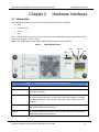
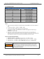
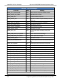
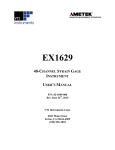
Figure 1 below shows the locations of the connectors on the 2400/2500 rear panel. Descriptions of the
connectors are given in Table 1 below.
NOTE: Your 2400/2500 may look slightly different, depending on series and model.
Figure 1. 2400/2500 Rear Panel
LAN
GPIB
Table 1
Name
RS-232
USB
2400/2500 Hardware Interfaces Description
Description
GPIB
A 24-pin IEEE STD 488.2 connector for control of the instrument during remote
operation using GPIB.
RS-232
A DB-9 connector for control of the instrument during remote operation using
RS-232 serial communications. A USB to Serial Cable Port Adapter is included
with the 2400/2500 for controlling the instrument via the USB port on a host
computer.
USB
A USB connector for control of the instrument during remote operation using
USB 2.0 (full speed) communications
Ethernet
An Ethernet connector for control of the instrument during remote operation
using LAN interface communications.
Programming Manual, Part Number 34783, Rev A, July 2009
5
3. Hardware Interfaces
Giga-tronics 2400/2500 Series Microwave Signal Generators
3.2 Configure the 2400/2500 Hardware Interface
3.2.1 Using the Included USB Cable
A USB 2.0 Type A Male to Type B Male cable shipped with the 2400/2500, and provides you with the
simplest way to connect a computer to the 2400/2500. The cable connects between a USB port on the
computer, and the USB port on the 2400/2500.
To use this cable, you must first install Automation Xpress and the USB driver on the computer. See
Table 40 on page 150.
3.2.2 Assign a GPIB Address to the 2400/2500
To connect a computer to the 2400/2500 via GPIB, the 2400/2500 must be assigned a GPIB address. The
procedure below describes how to assign a GPIB address to a 2400/2500.
Table 2
Setup GPIB Address
Step
Action
1.
On the front panel of the 2400/2500, press
to display the System menus, and if the
SYSTEM 2 menu does not appear in the display, press the bottom-most interactive softkey until it
does.
2.
Enter the desired GPIB address using either the numeric keypad or
SYSTEM
.
End of Procedure
3.2.3 Configure the Computer’s RS-232 for Remote Operation
Table 3 below gives information for configuring an RS-232 port on a computer to communicate with the
2400/2500.
Table 3
6
RS-232 Communication Settings
Baud rate
115200
Data Bits
8
Parity
None
Stop bits
1
Handshake
None
Programming Manual, Part Number 34783, Rev A, July 2009
Giga-tronics 2400/2500 Series Microwave Signal Generators
3. Hardware Interfaces
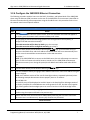
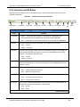
3.2.4 Configure the 2400/2500 Ethernet Connection
The following procedure explains how to set the DHCP, IP Address, and Subnet Mask of the 2400/2500
when using the Ethernet (LAN) connector on the rear of the 2400/2500. The instrument is identified via
Ethernet connection during remote operations using the IP address set in this procedure. Each unit on
the network must have a unique IP address.
Table 4
Step
Configure Remote Operation Using the LAN
Action
SYSTEM
1.
Press
to invoke the System menus, and if the SYSTEM 4 menu does not appear in
the display, press the bottom-most interactive softkey until it does.
2.
Are you going to connect the LAN using Dynamic Host Configuration Protocol (DHCP), or
configure the LAN connection manually?
If the LAN connection will be done by DHCP: go to the next step.
If the LAN connection will be configured manually: go to Step 4.
3.
Press the DHCP softkey and set DCHP to On using the
keys. The instrument will try to
connect to the DCHP server and the IP address and Subnet Mask will be set automatically from
the first server that establishes communication via the LAN connection.
Go to Step 7.
NOTE: If the 2400/2500 fails to connect to the DCHP server, the unit will attempt to reconnect
again. If it fails to connect to the DCHP server a second time, the 2400/2500 will attempt to
reconnect once every hour. During this period, the IP address and subnet mask values will be
zero.
4.
Press the DHCP softkey and set DCHP to Off using the
5.
Press the IP Address softkey to highlight the IP Address menu item. Enter the IP address using the
numeric keypad.
NOTE: An IP address consists of four sets of three-digit numbers, separated by decimal points.
The following example demonstrates how to properly enter an IP address:
190.165.001.034
An invalid IP entry will be displayed as Invalid IP Input in the Step Size/Error Message section of
the display. Examples of invalid addresses are values greater than 255, less than zero (negative
sign), values greater than three digits per set or more or less than 4 sets of three-digit values.
6.
Press the Subnet Mask softkey to highlight the Subnet Mask menu item. Enter the subnet mask
number using the sequence defined in the previous step.
7.
Confirm that the server has connected to 2400/2500 by observing the Link Status menu item.
This menu item is an indicator only. No entry key functions are processed.
keys.
End of Procedure
Programming Manual, Part Number 34783, Rev A, July 2009
7
3. Hardware Interfaces
Giga-tronics 2400/2500 Series Microwave Signal Generators
This page is intentionally blank
8
Programming Manual, Part Number 34783, Rev A, July 2009
Giga-tronics 2400/2500 Microwave Synthesizer Series
Chapter 4.
4. Programming Interfaces
Programming Interfaces
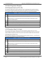
4.1 Introduction
This chapter describes the different programming interfaces and methods for remotely controlling a
2400/2500.
4.2 Select the Remote Programming Language
The 2400/2500 can communicate using a variety of languages. Every 2400/2500 is capable of
communications using the SCPI (Standard Commands for Programmable Instruments) language or any
Giga-tronics native command set. Optional Command Sets are available as well.
Table 5 below describes how to use the 2400/2500 front panel in local operating mode to select a
language from the Language Menu.
Table 5
Step
1.
Select the Remote Language
Action
•
If the instrument IS NOT in remote operating mode, press the LOCAL button once to invoke
the Language menus in the display.
•
If the instrument IS IN remote operating mode, press the LOCAL button twice - once to take
it out of remote operating mode, then again to invoke the Language menus in the display.
2.
If the desired language does not appear in the parameter area of the display, press the bottommost interactive softkey to go to the next menu. There are three screens for the Language
menus. Use the bottom softkey to go through the screens until you find the language you want
to use.
3.
If the message “Option not installed” appears next to a given language in the menu area of the
display, that language is optional and not currently available in the instrument. Contact Gigatronics customer support to inquire about purchasing additional language options.
4.
Once you have located the desired language, press the associated interactive softkey in the
display to select it.
End of Procedure
Programming Manual, Part Number 34783, Rev A, July 2009
9
4. Programming Interfaces
Giga-tronics 2400/2500 Microwave Synthesizer Series
4.3 Dynamic Link Library (DLL)
A DLL is a collection of routines that can be used by applications or other DLLs. A DLL is provided on the
CD-ROM that is included with the 2400/2500 Microwave Signal Generator. When you install Automation
Xpress from the CD-ROM onto your computer, the DLL is loaded onto your computer. The routines in
the DLL can be used in Visual C++, Visual Basic, and other applications.
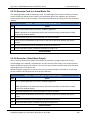
4.3.1 Adding the DLL to Programming Projects
The following procedures describe how to include the DLL into Visual C++ and Visual Basic projects.
4.3.1.1 Add the DLL to a Visual C++ Project
Table 6
Step
Add the DLL to a Visual C++ Project
Action
1.
Create a Visual C++ project.
2.
Copy GT2400.dll from C:\Program Files\Giga-tronics\AX\bin into your project’s executable folder
for run time calls. (e.g. folder named “Debug”)
3.
Copy GT2400.lib from C:\Program Files\Giga-tronics\AX\lib into your project.
4.
Copy all files from C:\Program Files\Giga-tronics\AX\include into your project.
5.
Copy the following line into your application C/C++ files:
“#include “GT2400.h”
6.
Make DLL function calls as needed from any .cpp files where GT2400.h file is included.
7.
Build your application.
End of Procedure
4.3.1.2 Add the DLL to a Visual Basic Project
Table 7
Step
Add the DLL to a Visual Basic Project
Action
1.
Create a Visual Basic project.
2.
Copy GT2400.dll from C:\Program Files\Giga-tronics\AX\bin into your project’s executable folder
for run time calls.
3.
Copy DLLDeclare.bas from C:\Program Files\Giga-tronics\AX\VBModule to the project folder.
4.
Make DLL function calls as needed from any files in the project.
5.
Build the application.
End of Procedure
10
Programming Manual, Part Number 34783, Rev A, July 2009
Giga-tronics 2400/2500 Microwave Synthesizer Series
4. Programming Interfaces
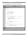
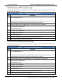
4.3.2 Programming Examples Using the DLL
4.3.2.1 CW Operation Using Visual C++
NOTE: Only bold faced code lines are unique to a specific operation mode. All other lines are supporting
lines shared by both CW and List modes.
Step
Description
1.
Perform steps 1 through 5 in Table 6 on page 10 to add the DLL to a Visual C++ project.
2.
Write the following code:
#include "GT2400.h"
#include "stdio.h"
#define SUCCESS
0
//This routine sets CW frequency and power of a 2400/2500
synthesizer
//at your choice through GPIB at address 6.
void main(void)
{
STATUS status;
unsigned long instrumentHandle;
double Frequency = 1000;
double Power = 0;
status = GT2400_OpenConnection(0,6,0,&instrumentHandle);
if(status < SUCCESS )
{
char statusText[256];
GT2400_GetErrorMessage(status, statusText);
printf("Status Message %s\n",statusText);
}
status = GT2400_SetRF(instrumentHandle, 1);
printf("Frequency (MHz) =");
scanf("%lf",&Frequency);
printf("Power (dBm) =");
scanf("%lf",&Power);
status = GT2400_SetCW(instrumentHandle,Frequency,Power,0,0);
status = GT2400_CloseAllConnections();
}
3.
Build the project.
4.
Run the program.
End of Example
Programming Manual, Part Number 34783, Rev A, July 2009
11
4. Programming Interfaces
Giga-tronics 2400/2500 Microwave Synthesizer Series
4.3.2.2 Programming Example; CW Operation Using Visual Basic
Step
Description
1.
Perform steps 1 through 3 of Table 7 on page 10 to create a Visual Basic project.
2.
Write the following
‘This routine sets CW frequency and power of a 2400/2500
synthesizer
‘through GPIB at address 6.
Dim
Dim
Dim
Dim
Dim
status As Long
instrumentHandle As Long
Frequency As Double
Power As Double
statusText As String
statusText = Space(100)
status = GT2400_OpenConnection(0,6,0,instrumentHandle)
If status < SUCCESS Then
GT2400_GetErrorMessage(status, statusText)
MsgBox statusText
End If
status = GT2400_SetRF(instrumentHandle, 1)
Frequency = 20000 ‘MHz
Power = 10
status = GT2400_SetCW(instrumentHandle,Frequency,Power,0,0)
status = GT2400_CloseAllConnections()
3.
Build the project.
4.
Run the program.
End of example
12
Programming Manual, Part Number 34783, Rev A, July 2009
Giga-tronics 2400/2500 Microwave Synthesizer Series
4. Programming Interfaces
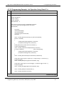
4.3.2.3 Programming Example; List Operation Using Visual C++
Step
Description
1.
Perform steps 1 through 5 of Table 6 to create a Visual C++ project.
2.
Write the following code:
#include <windows.h>
#include <stdio.h>
#include "gt2400.h"
#define SUCCESS 0
//This routine can load any list file to 2400/2500 synthesizer
//and set up repeat type and trigger type at user choice.
void main(void)
{
long status;
char listFileName[80];
char statusText[256];
unsigned long instrumentHandle;
short tmp;
status = GT2400_OpenConnection(0, 6, 0, &instrumentHandle);
if(status < SUCCESS )
{
GT2400_GetErrorMessage(status, statusText);
printf("Status Message %s\n",statusText);
}
printf("Please enter the file name to be loaded:\n ");
scanf("%s",&listFileName);
status = GT2400_LoadListFromFile(listFileName, statusText);
if ( status < SUCCESS )
//Error during loading
{
GT2400_GetErrorMessage(status, statusText);
printf("Status Message %s\n",statusText);
}
status = GT2400_DownloadList(instrumentHandle, listFileName);
printf("Enter Repeat Type (0 = single step; 1 = single sweep; 2 = continuous) =");
scanf("%d",&tmp);
status = GT2400_SetRepeatType(instrumentHandle, tmp);
printf("Enter Trigger Type (0 = External trigger; 1 = Software trigger or GET) =");
scanf("%d",&tmp);
status = GT2400_SetTriggerType(instrumentHandle, tmp);
status = GT2400_SetRF(instrumentHandle, 1);
status = GT2400_CloseAllConnections();
}
Continued next page
Programming Manual, Part Number 34783, Rev A, July 2009
13
4. Programming Interfaces
Giga-tronics 2400/2500 Microwave Synthesizer Series
Step
Description
3.
Build the project.
4.
Run the program.
5.
Send trigger.
End of example
14
Programming Manual, Part Number 34783, Rev A, July 2009
Giga-tronics 2400/2500 Microwave Synthesizer Series
4. Programming Interfaces
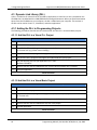
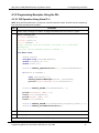
4.3.2.4 Programming Example; Generate Two Frequencies
The following example shows how to write code for generating two CW frequencies, separated by a 40
second delay.
Step
1.
Description
//This example sets two CW frequencies in sequence, separated by a 40 second delay.
#include "GT2400.h"
#include "stdio.h"
#include "winbase.h"
void main(void)
{
long STATUS;
unsigned long instrumentHandle;
printf("f= 23.456789 MHz, Power = 5 dBm\n");
STATUS = GT2400_OpenConnection(0, 6, 0, &instrumentHandle);
STATUS = GT2400_SetRF(instrumentHandle, 1);
STATUS = GT2400_SetCW(instrumentHandle, 23.456789, 5);
printf("Waiting for 40 seconds....\n");
//Reserve time for frequency counter to operate correctly
Sleep(40000);
printf("f= 33.4567891 MHz, Power = 0 dBm\n");
STATUS = GT2400_SetCW(instrumentHandle, 33.4567891, 0);
STATUS = GT2400_CloseAllConnections();
}
End of example
Programming Manual, Part Number 34783, Rev A, July 2009
15
4. Programming Interfaces
Giga-tronics 2400/2500 Microwave Synthesizer Series
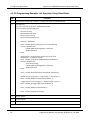
4.3.2.5 Programming Example: List Operation Using Visual Basic
Step
Description
1.
Perform step 1 through step 3 of Table 7 on page 10 to create a Visual Basic project.
2.
Write following:
‘This routine can load any list file to 2400/2500 synthesizer
‘and set up repeat type and trigger type.
Dim status As Long
Dim listFileName As String
Dim statusText As String
Dim instrumentHandle As Long
statusText = Space(100)
status = GT2400_OpenConnection(0, 6, 0, instrumentHandle)
If status < SUCCESS Then
GT2400_GetErrorMessage(status, statusText)
MsgBox statusText
End If
‘Please replace C:\Temp\ListTest.txt with your list file name.
listFileName = “C:\Temp\ListTest.txt”
status = GT2400_LoadListFromFile(listFileName, listFileName)
If status < SUCCESS Then
‘Error during loading
GT2400_GetErrorMessage(status, statusText)
MsgBox statusText
End If
status = GT2400_DownloadList(instrumentHandle, listFileName)
‘Repeat Type (0 = single step; 1 = single sweep; 2 = continuous) =")
status = GT2400_SetRepeatType(instrumentHandle, 1)
‘ Trigger Type (0 = External trigger; 1 = Software trigger or GET) =")
status = GT2400_SetTriggerType(instrumentHandle, 0)
status = GT2400_SetRF(instrumentHandle, 1)
status = GT2400_CloseAllConnections()
3.
Build the project.
4.
Run the program.
5.
Send trigger.
End of example
16
Programming Manual, Part Number 34783, Rev A, July 2009
Giga-tronics 2400/2500 Microwave Synthesizer Series
4. Programming Interfaces
4.3.3 DLL Functions
This section describes the DLL functions in detail.
Programming Manual, Part Number 34783, Rev A, July 2009
17
4. Programming Interfaces
Giga-tronics 2400/2500 Microwave Synthesizer Series
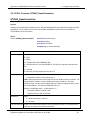
4.3.3.1 DLL Function; GT2400_FindInstruments
GT2400_FindInstruments
Purpose
Find the addresses of instruments, either through GPIB or RS232, connected to PC.
Syntax
STATUS GT2400_FindInstruments(
Parameter
const short connectionType,
short addresses[],
short *pCount)
Description
connectionType
Input: Connection type.
0 = GPIB,
1 = RS232
2,3 = SPECIAL (NOT FOR COMMON USE)
4 = GPIB Connection via remote SERVER PC (TCP/IP)
addresses
Output: Array of GPIB addresses or COM port numbers of all the Giga-tronics
instruments connected.
(Note: In case the RS232 connection interface is selected, the first element returned
in this array is the first serial port that is connected to a Giga-tronics instrument
followed by the remaining serial port numbers on the PC.)
Example 1:
There are total of 4 COM ports on a PC, and only COM port 1 is connected to a Gigatronics instrument, the returned result will be
addresses[0] = 1
addresses[1] = 2
addresses[2] = 3
addresses[3] = 4
Example 2:
There are total of 4 COM ports on a PC, and only COM port 3 is connected to a Gigatronics instrument, the returned result will be
addresses[0] = 3
addresses[1] = 4
pCount
Output: Total number of instruments connected to PC through the specified
interface.
18
Programming Manual, Part Number 34783, Rev A, July 2009
Giga-tronics 2400/2500 Microwave Synthesizer Series
4. Programming Interfaces
4.3.3.2 DLL Function; GT2400_OpenConnection
GT2400_OpenConnection
Purpose
Establish the communication between the PC and the 2400/2500 with the specified connection interface
and address. For an Ethernet connection, call GT2400_SetIPAddress function first to establish the
TCP/IP address of the instrument.
Syntax
STATUS GT2400_OpenConnection(
const short connectionType,
const short address,
const short resetDevice
unsigned long *instrumentHandle)
Parameter
Description
connectionType
Input: Connection interface:
0 = GPIB
1 = RS232
2,3 = SPECIAL (NOT FOR COMMON USE)
4 = GPIB Connection via remote SERVER PC (TCP/IP) (not supported after Revision
3.3)
5 = reserved
6 = Ethernet (TCP/IP) (supported from Rev 3.3)
address
Input: GPIB address number if ConnectionType = 0
or COM port number if ConnectionType = 1
Note: GPIB communication board index can be set if GPIB interface is selected. The
2 byte (SHORT) “address” contains GPIB board index and address. The most
significant byte is used to set GPIB board index and the least significant byte is used
to set GPIB address. The default GPIB board index is 0.
Example: GPIB board index = 1; GPIB address = 6
Parameter, address = 0x100 | 0x6 =
0x106 (in Hex.) or 262 (in Decimal)
resetDevice
Input:
1 = Reset instrument in start up
0 = No reset
instrumentHandle Output: The unique identification of the connected instrument. This handle can be
used later to operate on multiple instruments.
Programming Manual, Part Number 34783, Rev A, July 2009
19
4. Programming Interfaces
Giga-tronics 2400/2500 Microwave Synthesizer Series
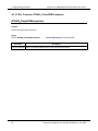
4.3.3.3 DLL Function; GT2400_CloseGPIBConnection
GT2400_CloseGPIBConnection
Purpose
Close one specific GPIB connection.
Syntax
STATUS GT2400_CloseGPIBConnection(
Parameter
const unsigned long instrumentHandle)
Description
instrumentHandle Input: The unique identification of the connected instrument.
20
Programming Manual, Part Number 34783, Rev A, July 2009
Giga-tronics 2400/2500 Microwave Synthesizer Series
4. Programming Interfaces
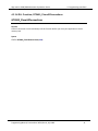
4.3.3.4 DLL Function; GT2400_CloseAllConnections
GT2400_CloseAllConnections
Purpose
Close all connection. You should always call this function before you close your application to avoid
memory leak.
Syntax
STATUS GT2400_CloseAllConnections(void)
Programming Manual, Part Number 34783, Rev A, July 2009
21
4. Programming Interfaces
Giga-tronics 2400/2500 Microwave Synthesizer Series
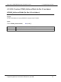
4.3.3.5 DLL Function; GT2400_SetGPIBAddress
GT2400_SetGPIBAddress
Purpose
Set the GPIB address.
Syntax
STATUS GT2400_SetGPIBAddress(
const unsigned long instrumentHandle,
const short address,
unsigned long *updatedInstrumentHandle)
Parameter
Description
instrumentHandle
Input: The unique identification of the instrument.
address
Input: GPIB address.
updatedInstrumentHandle Output: Updated instrument handle after this function completes.
22
Programming Manual, Part Number 34783, Rev A, July 2009
Giga-tronics 2400/2500 Microwave Synthesizer Series
4. Programming Interfaces
4.3.3.6 DLL Function; GT2400_SetServerIPAddr (for Rev 3.0 and above)
GT2400_SetServerIPAddr (for Rev 3.0 and above)
Purpose
Set the TCP/IP address of remote SERVER PC. (example: 194.177.0.482)
Syntax
STATUS GT2400_SetServerIPAddr(
Parameter
ipAddr
char ipAddr[])
Description
Input: TCP/IP address of remote SERVER PC
Programming Manual, Part Number 34783, Rev A, July 2009
23
4. Programming Interfaces
Giga-tronics 2400/2500 Microwave Synthesizer Series
4.3.3.7 DLL Function; GT2400_GetIPAddress (supported from Revision 3.3)
GT2400_GetIPAddress (supported from Revision 3.3)
Purpose
Get the TCP/IP address of the instrument. (example: 194.177.0.482).
Syntax
STATUS GT2400_GetIPAddress(
Parameter
ipAddr
24
char ipAddr[])
Description
Output: TCP/IP address for the instrument
Programming Manual, Part Number 34783, Rev A, July 2009
Giga-tronics 2400/2500 Microwave Synthesizer Series
4. Programming Interfaces
4.3.3.8 DLL Function; GT2400_SetIPAddress (supported from Revision 3.3)
GT2400_SetIPAddress (supported from Revision 3.3)
Purpose
Set the TCP/IP address for the instrument. (example: 194.177.0.482) For establishing Ethernet
connection with the instrument, this function needs to be called prior to calling
GT2400_OpenConnection function.
Syntax
STATUS GT2400_SetIPAddress(
Parameter
ipAddr
char ipAddr[])
Description
Input: TCP/IP address for the instrument
Programming Manual, Part Number 34783, Rev A, July 2009
25
4. Programming Interfaces
Giga-tronics 2400/2500 Microwave Synthesizer Series
4.3.3.9 DLL Function; GT2400_ResetInstrument
GT2400_ResetInstrument
Purpose
Reset the instrument to factory defaults.
Syntax
STATUS GT2400_ResetInstrument(
Parameter
const unsigned long instrumentHandle)
Description
instrumentHandle Input: The unique identification of the instrument
26
Programming Manual, Part Number 34783, Rev A, July 2009
Giga-tronics 2400/2500 Microwave Synthesizer Series
4.3.3.10
4. Programming Interfaces
DLL Function; GT2400_GetRF
GT2400_GetRF
Purpose
Get the state of RF output
Syntax
STATUS GT2400_GetRF(
const unsigned long instrumentHandle,
short *RFState)
Parameter
Description
instrumentHandle Input: The unique identification of the instrument
RFState
Output:
1 = RF is on
0 = RF is off
Programming Manual, Part Number 34783, Rev A, July 2009
27
4. Programming Interfaces
4.3.3.11
Giga-tronics 2400/2500 Microwave Synthesizer Series
DLL Function; GT2400_SetRF
GT2400_SetRF
Purpose
Set the RF on or off.
Syntax
STATUS GT2400_SetRF(
const unsigned long instrumentHandle,
const short RFState)
Parameter
Description
instrumentHandle Input: The unique identification of the instrument
RFState
28
Input:
1 = Turn on
0 = Turn off RF output
Programming Manual, Part Number 34783, Rev A, July 2009
Giga-tronics 2400/2500 Microwave Synthesizer Series
4.3.3.12
4. Programming Interfaces
DLL Function; GT2400_GetAttenuation
GT2400_GetAttenuation
Purpose
Get the attenuation value.
Syntax
STATUS GT2400_GetAttenuation(
Parameter
const unsigned long instrumentHandle,
short *pAttenuation)
Description
instrumentHandle Input: The unique identification of the instrument.
pAttenuation
Output: current attenuation in the instrument.
If returned value = -10, it is in AUTO attenuation mode;
Else If returned value = -99, there is no attenuator option installed;
Else attenuation is in MANUAL mode with value = *pAttenuation
Programming Manual, Part Number 34783, Rev A, July 2009
29
4. Programming Interfaces
4.3.3.13
Giga-tronics 2400/2500 Microwave Synthesizer Series
DLL Function; GT2400_SetAttenuation
GT2400_SetAttenuation
Purpose
Set the attenuation of the output power of the 2400/2500.
Syntax
STATUS GT2400_SetAttenuation(
Parameter
const unsigned long instrumentHandle,
const short attenuation)
Description
instrumentHandle Input: The unique identification of the instrument
attenuation
30
Input: attenuation value, e.g.
If attenuation = -10, set to auto attenuation;
Else If attenuation >= 0, set to manual attenuation with value = attenuation.
attenuation = [0, 10,20,30,40,50,60,70,80,90]
Programming Manual, Part Number 34783, Rev A, July 2009
Giga-tronics 2400/2500 Microwave Synthesizer Series
4.3.3.14
4. Programming Interfaces
DLL Function; GT2400_GetALCLeveling
GT2400_GetALCLeveling
Purpose
Get the current ALC leveling source of the instrument.
Syntax
STATUS GT2400_GetALCLeveling(
Parameter
const unsigned long instrumentHandle,
short *alcLeveling)
Description
instrumentHandle Input: The unique identification of the instrument
alcLeveling
Output: Current ALC leveling source of the instrument
= 0: Internal
= 1: Power Meter
= 2: Positive Diode
= 3: Negative
Programming Manual, Part Number 34783, Rev A, July 2009
31
4. Programming Interfaces
4.3.3.15
Giga-tronics 2400/2500 Microwave Synthesizer Series
DLL Function; GT2400_SetALCLeveling
GT2400_SetALCLeveling
Purpose
Set the ALC leveling source to the instrument.
Syntax
STATUS GT2400_SetALCLeveling(
Parameter
const unsigned long instrumentHandle,
const short alcLeveling)
Description
instrumentHandle Input: The unique identification of the instrument
alcLeveling
32
Input: ALC leveling source set to the instrument
= 0: Internal
= 1: Power Meter
= 2: Positive Diode
= 3: Negative
Programming Manual, Part Number 34783, Rev A, July 2009
Giga-tronics 2400/2500 Microwave Synthesizer Series
4.3.3.16
4. Programming Interfaces
DLL Function; GT2400_GetErrorMessage
GT2400_GetErrorMessage
Purpose
Convert STATUS code to the corresponding description.
Syntax
STATUS GT2400_GetErrorMessage(
const long errorID,
char statusText[])
Parameter
Description
errorID
STATUS of any DLL function
statusText
Text description of the STATUS
Programming Manual, Part Number 34783, Rev A, July 2009
33
4. Programming Interfaces
4.3.3.17
Giga-tronics 2400/2500 Microwave Synthesizer Series
DLL Function; GT2400_GetDLLVersion
GT2400_GetDLLVersion
Purpose
Return the DLL version.
Syntax
STATUS GT2400_GetDLLVersion(
Parameter
version
34
char version[])
Description
DLL version
Programming Manual, Part Number 34783, Rev A, July 2009
Giga-tronics 2400/2500 Microwave Synthesizer Series
4.3.3.18
4. Programming Interfaces
DLL Function; GT2400_GetCW
GT2400_GetCW
Purpose
Read the current CW setting (data) from the instrument.
Syntax
STATUS GT2400_GetCW(
const unsigned long instrumentHandle,
double *frequency,
double *power)
Parameter
Description
instrumentHandle Input: The unique identification of the instrument
frequency
Output: CW frequency (in MHz)
power
Output: CW power (in dBm)
Programming Manual, Part Number 34783, Rev A, July 2009
35
4. Programming Interfaces
4.3.3.19
Giga-tronics 2400/2500 Microwave Synthesizer Series
DLL Function; GT2400_GetCWDataLimit
GT2400_GetCWDataLimit
Purpose
Get the CW data limits of the instrument.
Syntax
STATUS GT2400_GetCWDataLimit(
Parameter
const unsigned long instrumentHandle,
double *pMinFrequency,
double *pMaxFrequency,
double *pMinPower,
double *pMaxPower)
Description
instrumentHandle Input: The unique identification of the instrument
pMinFrequency
Output: Minimum frequency allowed (in MHz)
pMaxFrequency
Output: Maximum frequency allowed (in MHz)
pMinPower
Output: Minimum power allowed (in dBm)
pMaxPower
Output: Maximum power allowed (in dBm)
36
Programming Manual, Part Number 34783, Rev A, July 2009
Giga-tronics 2400/2500 Microwave Synthesizer Series
4.3.3.20
4. Programming Interfaces
DLL Function; GT2400_SetCW
GT2400_SetCW
Purpose
Set CW.
Syntax
STATUS GT2400_SetCW(
const unsigned long instrumentHandle,
const double frequency,
const double power)
Parameter
Description
instrumentHandle Input: The unique identification of the instrument
frequency
Input: CW frequency (in MHz)
power
Input: CW power (in dBm)
Programming Manual, Part Number 34783, Rev A, July 2009
37
4. Programming Interfaces
4.3.3.21
Giga-tronics 2400/2500 Microwave Synthesizer Series
DLL Function; GT2400_GetPowerOffset
GT2400_GetPowerOffset
Purpose
Get the current power offset value of the instrument.
Syntax
STATUS GT2400_GetPowerOffset(
Parameter
const unsigned long instrumentHandle,
double *powerOffset)
Description
instrumentHandle
Input: The unique identification of the instrument
powerOffset
Output: Current power offset value of the instrument
38
Programming Manual, Part Number 34783, Rev A, July 2009
Giga-tronics 2400/2500 Microwave Synthesizer Series
4.3.3.22
4. Programming Interfaces
DLL Function; GT2400_SetPowerOffset
GT2400_SetPowerOffset
Purpose
Set the power offset value to the instrument.
Syntax
STATUS GT2400_SetPowerOffset(
Parameter
const unsigned long instrumentHandle,
const double powerOffset)
Description
instrumentHandle
Input: The unique identification of the instrument
powerOffset
Input: Power offset value set to the instrument
Programming Manual, Part Number 34783, Rev A, July 2009
39
4. Programming Interfaces
4.3.3.23
Giga-tronics 2400/2500 Microwave Synthesizer Series
DLL Function; GT2400_GetPowerSlope
GT2400_GetPowerSlope
Purpose
Get the current power slope value of the instrument.
Syntax
STATUS GT2400_GetPowerSlope(
Parameter
const unsigned long instrumentHandle,
double *powerSlope)
Description
instrumentHandle
Input: The unique identification of the instrument
powerSlope
Output: Current power slope value of the instrument
40
Programming Manual, Part Number 34783, Rev A, July 2009
Giga-tronics 2400/2500 Microwave Synthesizer Series
4.3.3.24
4. Programming Interfaces
DLL Function; GT2400_SetPowerSlope
GT2400_SetPowerSlope
Purpose
Set the power slope value to the instrument.
Syntax
STATUS GT2400_SetPowerSlope(
Parameter
const unsigned long instrumentHandle,
const double powerSlope)
Description
instrumentHandle
Input: The unique identification of the instrument
powerSlope
Input: Power slope value set to the instrument
Programming Manual, Part Number 34783, Rev A, July 2009
41
4. Programming Interfaces
4.3.3.25
Giga-tronics 2400/2500 Microwave Synthesizer Series
DLL Function; GT2400_DownloadList
GT2400_DownloadList
Purpose
Download a list to the GT2400 synthesizer. The file can be prepared beforehand by either MS Excel, or
any text editor or AutomationXpress GUI or AutomationXpress DLL list editing functions.
Syntax
STATUS GT2400_DownloadList(
Parameter
const unsigned long instrumentHandle,
const char listPath[])
Description
instrumentHandle
Input: The unique identification of the instrument
listPath
Input: Complete path (path + list name) of the list being downloaded to the unit
42
Programming Manual, Part Number 34783, Rev A, July 2009
Giga-tronics 2400/2500 Microwave Synthesizer Series
4.3.3.26
4. Programming Interfaces
DLL Function; GT2400_GetRepeatType
GT2400_GetRepeatType
Purpose
Get the repeat type of the list to be triggered.
Syntax
STATUS GT2400_GetRepeatType(
const unsigned long instrumentHandle,
short *repeatType)
Parameter
Description
instrumentHandle
Input: The unique identification of the instrument
repeatType
Output:
0 = single step;
1 = single sweep;
2 = continuous
Programming Manual, Part Number 34783, Rev A, July 2009
43
4. Programming Interfaces
4.3.3.27
Giga-tronics 2400/2500 Microwave Synthesizer Series
DLL Function; GT2400_SetRepeatType
GT2400_SetRepeatType
Purpose
Set the repeat type of the list to be triggered.
Syntax
STATUS GT2400_SetRepeatType(
const unsigned long instrumentHandle,
const short repeatType)
Parameter
Description
instrumentHandle
Input: The unique identification of the instrument
repeatType
Input:
0 = single step;
1 = single sweep;
2 = continuous
44
Programming Manual, Part Number 34783, Rev A, July 2009
Giga-tronics 2400/2500 Microwave Synthesizer Series
4.3.3.28
4. Programming Interfaces
DLL Function; GT2400_GetTriggerType
GT2400_GetTriggerType
Purpose
Get the trigger type to trigger the list.
Syntax
STATUS GT2400_GetTriggerType(
const unsigned long instrumentHandle,
short *triggerType)
Parameter
Description
instrumentHandle
Input: The unique identification of the instrument
triggerType
Output:
0 = External trigger;
1 = GET;
2 = Software trigger
Programming Manual, Part Number 34783, Rev A, July 2009
45
4. Programming Interfaces
4.3.3.29
Giga-tronics 2400/2500 Microwave Synthesizer Series
DLL Function; GT2400_SetTriggerType
GT2400_SetTriggerType
Purpose
Set the trigger type to trigger the list.
Syntax
STATUS GT2400_SetTriggerType(
const unsigned long instrumentHandle,
const short triggerType)
Parameter
Description
instrumentHandle
Input: The unique identification of the instrument
triggerType
Input:
0 = External trigger;
1 = GET;
2 = Software trigger
46
Programming Manual, Part Number 34783, Rev A, July 2009
Giga-tronics 2400/2500 Microwave Synthesizer Series
4.3.3.30
4. Programming Interfaces
DLL Function; GT2400_SetListScanDirection
GT2400_SetListScanDirection
Purpose
Set the list scan direction.
Syntax
STATUS GT2400_SetListScanDirection(
Parameter
const unsigned long instrumentHandle,
const short direction)
Description
instrumentHandle
Input: The unique identification of the instrument.
direction
Input:
0 = scan from first point to last point;
1 = scan from last to first.
Programming Manual, Part Number 34783, Rev A, July 2009
47
4. Programming Interfaces
4.3.3.31
Giga-tronics 2400/2500 Microwave Synthesizer Series
DLL Function; GT2400_SoftwareTrigger
GT2400_SoftwareTrigger
Purpose
Use the software to trigger the current list.
Syntax
STATUS GT2400_SoftwareTrigger(
Parameter
instrumentHandle
48
const unsigned long instrumentHandle)
Description
Input: The unique identification of the instrument
Programming Manual, Part Number 34783, Rev A, July 2009
Giga-tronics 2400/2500 Microwave Synthesizer Series
4.3.3.32
4. Programming Interfaces
DLL Function; GT2400_GroupExecutionTrigger
GT2400_GroupExecutionTrigger
Purpose
Send a Group Execution Trigger (G.E.T. is defined in IEEE 488) to all the instruments connected to PC via
GPIB.
Syntax
STATUS GT2400_GroupExecutionTrigger(
void)
Programming Manual, Part Number 34783, Rev A, July 2009
49
4. Programming Interfaces
4.3.3.33
Giga-tronics 2400/2500 Microwave Synthesizer Series
DLL Function; GT2400_GetListDataLimit
GT2400_GetListDataLimit
Purpose
Get the list data limits of the instrument.
Syntax
STATUS GT2400_GetListDataLimit(
Parameter
const unsigned long instrumentHandle,
short *pMaxListPts,
double *pMinStepTime,
double *pMaxStepTime,
double *pMinRFOffTime,
double *pMaxRFOffTime,
double *pMinSyncOutDelay,
double *pMaxSyncOutDelay)
Description
instrumentHandle
Input: The unique identification of the instrument.
pMaxListPts
Output: Maximum number of list points
pMinStepTime
Output: Minimum list step time (in ms)
pMaxStepTime
Output: Maximum list step time (in ms)
pMinRFOffTime
Output: Minimum list RF off time (in ms)
pMaxRFOffTime
Output: Maximum list RF off time (in ms)
pMinSyncOutDelay
Output: Minimum list sync out delay (in ms)
pMaxSyncOutDelay
Output: Maximum list sync out delay (in ms)
50
Programming Manual, Part Number 34783, Rev A, July 2009
Giga-tronics 2400/2500 Microwave Synthesizer Series
4.3.3.34
4. Programming Interfaces
DLL Function; GT2400_LoadListFromFile
GT2400_LoadListFromFile
Purpose
Load a list from a disk file to PC RAM.
Syntax
STATUS GT2400_LoadListFromFile(
Parameter
const char filename[],
char errText[])
Description
filename
Input: Name of the file being loaded.
errText
Output: If there is an error detected by STATUS, errText will hold the description
of the problems.
Programming Manual, Part Number 34783, Rev A, July 2009
51
4. Programming Interfaces
4.3.3.35
Giga-tronics 2400/2500 Microwave Synthesizer Series
DLL Function; GT2400_CreateNewList
GT2400_CreateNewList
Purpose
Create a new list in PC RAM.
Syntax
STATUS GT2400_CreateNewList(
Parameter
listPath
52
const char listPath[])
Description
Input: Complete path (path + list name) of the list whose content is requested
Programming Manual, Part Number 34783, Rev A, July 2009
Giga-tronics 2400/2500 Microwave Synthesizer Series
4.3.3.36
4. Programming Interfaces
DLL Function; GT2400_SaveListToFile
GT2400_SaveListToFile
Purpose
Save a currently active list from RAM to a disk file.
Syntax
STATUS SaveListToFile (
Parameter
const char filename[],
char errText[])
Description
filename
Input: File name of list to be saved in.
errText
Output: If there is an error detected by STATUS, errText will hold the description
of the problems.
Programming Manual, Part Number 34783, Rev A, July 2009
53
4. Programming Interfaces
4.3.3.37
Giga-tronics 2400/2500 Microwave Synthesizer Series
DLL Function; GT2400_ActivateAList
GT2400_ActivateAList
Purpose
Activate the selected list so that the list is ready to respond to a trigger.
Syntax
STATUS GT2400_ActivateAList(
Parameter
listPath
54
const char listPath[])
Description
Input: Complete path (path + list name) of the list to be activated
Programming Manual, Part Number 34783, Rev A, July 2009
Giga-tronics 2400/2500 Microwave Synthesizer Series
4.3.3.38
4. Programming Interfaces
DLL Function; GT2400_GetListData
GT2400_GetListData
Purpose
Get the contents of the selected list from DLL allocated RAM into user application.
Syntax
STATUS GT2400_GetListData(
const char listPath[],
double *stepTime,
double *rfOffTime,
double *syncOutDelay,
unsigned char *syncInfo,
short *attenSetting
double *frequency,
double *power,
short *pListLen)
Parameter
Description
listPath
Input: Complete path (path + list name) of the list whose content is requested.
stepTime
Output: Step time of all list points (in ms)
rfOffTime
Output: RF off time of all list points (in ms)
syncOutDelay
Output: Sync out delay (in ms)
syncInfo
Output: Sync out pulse information for every list pt
attenSetting
Output: The attenuation setting for the current list
frequency
Output: Array of frequencies in the list (in MHz)
power
Output: Array of power in the list (in dBm)
pListLen
Output: Number of points in the list
Programming Manual, Part Number 34783, Rev A, July 2009
55
4. Programming Interfaces
4.3.3.39
Giga-tronics 2400/2500 Microwave Synthesizer Series
DLL Function; GT2400_GetListDataWithCorrection
GT2400_GetListDataWithCorrection
Purpose
Get the contents of the selected list from DLL allocated RAM into user application.
Syntax
STATUS GT2400_GetListDataWithCorrection ( const char listPath[],
double *stepTime,
double *rfOffTime,
double *syncOutDelay,
unsigned char *syncInfo,
short *attenSetting
double *frequency,
double *power,
double *correction,
short *pListLen)
Parameter
Description
listPath
Input: Complete path (path + list name) of the list whose content is requested.
stepTime
Output: Step time of all list points (in ms)
rfOffTime
Output: RF off time of all list points (in ms)
syncOutDelay
Output: Sync out delay (in ms)
syncInfo
Output: Sync out pulse information for every list pt
attenSetting
Output: The attenuation setting for the current list
frequency
Output: Array of frequencies in the list (in MHz)
power
Output: Array of power in the list (in dBm)
correction
Output: Array of correction in the list (in dBm)
pListLen
Output: Number of points in the list
56
Programming Manual, Part Number 34783, Rev A, July 2009
Giga-tronics 2400/2500 Microwave Synthesizer Series
4.3.3.40
4. Programming Interfaces
DLL Function; GT2400_SetCorrection
GT2400_SetCorrection
Purpose
Edit the correction of the selected list.
Syntax
STATUS GT2400_SetCorrection (
double *correction)
Parameter
correction
Description
Input: Array of correction
Programming Manual, Part Number 34783, Rev A, July 2009
57
4. Programming Interfaces
4.3.3.41
Giga-tronics 2400/2500 Microwave Synthesizer Series
DLL Function; GT2400_GetCorrection
GT2400_GetCorrection
Purpose
Get the correction of the selected list.
Syntax
STATUS GT2400_GetCorrection (
double *correction)
Parameter
correction
58
Description
Output: Array of correction
Programming Manual, Part Number 34783, Rev A, July 2009
Giga-tronics 2400/2500 Microwave Synthesizer Series
4.3.3.42
4. Programming Interfaces
DLL Function; GT2400_EditApplyCorrection
GT2400_EditApplyCorrection
Purpose
Set flag if correction should apply.
Syntax
STATUS GT2400_EditApplyCorrection ( bool correctionOn)
Parameter
correctionOn
Description
Input:
1 to turn on correction
0 to turn off
Programming Manual, Part Number 34783, Rev A, July 2009
59
4. Programming Interfaces
4.3.3.43
Giga-tronics 2400/2500 Microwave Synthesizer Series
DLL Function; GT2400_EditAListPoint
GT2400_EditAListPoint
Purpose
Edit a selected point in a list.
Syntax
STATUS GT2400_EditAListPoint(
const short position
const short insertType,
const char listPath[],
const unsigned char syncOutEnable,
const double frequency,
const double power)
Parameter
Description
position
Input: position in the list being edited. 0 < position ≤ current list length
insertType
Input: Insert Type:
0 = REPLACE
1 = INSERT BEFORE
2 = INSERT AFTER
listPath
Input: Complete path (path + list name) of the list
syncOutEnable
Input: Enable/disable sync out pulse generated in the editing point
frequency
Input: Frequency of the point being updated (in MHz)
power
Input: Power of the pt being updated (in dBm)
60
Programming Manual, Part Number 34783, Rev A, July 2009
Giga-tronics 2400/2500 Microwave Synthesizer Series
4.3.3.44
4. Programming Interfaces
DLL Function; GT2400_EditListPoints
GT2400_EditListPoints
Purpose
Edit multiple selected list points in a list with one function call.
Syntax
STATUS GT2400_ EditListPoints (
Parameter
const short position,
const short insertType,
const char listPath[],
const unsigned char *syncOutEnable,
const double *frequency,
const double *power,
const short listLen,
char errorTxt[])
Description
position
Input: position in the list being edited. 0 < position ≤ current list length
insertType
Input: Insert Type:
0 = REPLACE,
1 = INSERT BEFORE
2 = INSERT AFTER
(Note: if insertType = REPLACE, the existing list will be replaced with the newly
created list.)
listPath
Input: Complete path (path + list name) of the list
syncOutEnable
Input: Byte array that enables or disables sync out pulse generated in list.
frequency
Input: Array of frequency for list points (in MHz)
power
Input: Array of power for list points (in dBm)
listLen
Input: Number of list points being edited
errText
Output: If there is an error detected by STATUS, errText will hold the description
of the problem.
Programming Manual, Part Number 34783, Rev A, July 2009
61
4. Programming Interfaces
4.3.3.45
Giga-tronics 2400/2500 Microwave Synthesizer Series
DLL Function; GT2400_EditFreqRangeByStepFreq
GT2400_EditFreqRangeByStepFreq
Purpose
Establish a list or insert a sub-list to an existing list by inputting start frequency, stop frequency, step
frequency, and power.
Syntax
STATUS GT2400_ EditFreqRangeByStepFreq(
const short position,
const short insertType,
const char listPath[],
const double startFrequency,
const double stopFrequency,
const double stepFrequency,
const double power)
Parameter
Description
position
Input: position in the list being edited, 0 < position ≤ current list length
insertType
Input: Insert Type:
0 = REPLACE
1 = INSERT BEFORE
2 = INSERT AFTER
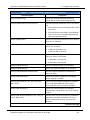
(Note: if insertType = REPLACE, the existing list will be replaced with the newly
created list.)
listPath
Input: Complete path (path + list name) of the list
startFrequency
Input: Start frequency (in MHz)
stopFrequency
Input: Stop frequency (in MHz)
stepFrequency
Input: Frequency step (in MHz)
power
Input: Power for all list points (in dBm)
62
Programming Manual, Part Number 34783, Rev A, July 2009
Giga-tronics 2400/2500 Microwave Synthesizer Series
4.3.3.46
4. Programming Interfaces
DLL Function; GT2400_EditPowerRangeByStepPower
GT2400_EditPowerRangeByStepPower
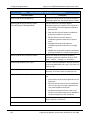
Purpose
Establish a list or insert a sub-list to an existing list by inputting start power, stop power, step
power, and frequency.
Syntax
STATUS GT2400_ EditPowerRangeByStepPower(
const short position,
const short insertType,
const char listPath[],
const double startPower,
const double stopPower,
const double stepPower,
const double frequency)
Parameter
Description
position
Input: position in the list being edited, 0 < position ≤ current list length
insertType
Input: Insert Type:
0 = REPLACE
1 = INSERT BEFORE
2 = INSERT AFTER
(Note: if insertType = REPLACE, the existing list will be replaced with the newly
created list.)
listPath
Input: Complete path (path + list name) of the list
startPower
Input: Start power (in dBm)
stopPower
Input: Stop power (in dBm)
stepPower
Input: Step power (in dBm)
frequency
Input: Frequency for all list points (in MHz)
Programming Manual, Part Number 34783, Rev A, July 2009
63
4. Programming Interfaces
4.3.3.47
Giga-tronics 2400/2500 Microwave Synthesizer Series
DLL Function; GT2400_EditFreqRangeByNumOfPts
GT2400_EditFreqRangeByNumOfPts
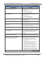
Purpose
Establish a long list or insert a sub-list to an existing list by inputting start frequency, stop frequency,
power, and number of list points.
Syntax
STATUS GT2400_EditFreqRangeByNumOfPts( const short position,
const short insertType,
const char listPath[],
const double startFrequency,
const double stopFrequency,
const double power,
const short numOfPts)
Parameter
Description
position
Input: position in the list being edited, 0 < position ≤ current list length
insertType
Input: Insert Type:
0 = REPLACE
1 = INSERT BEFORE
2 = INSERT AFTER
(Note: if insertType = REPLACE, the existing list will be replaced with the newly
created list.)
listPath
Input: Complete path (path + list name) of the list
startFrequency
Input: Start frequency for range insertion (in MHz)
stopFrequency
Input: Stop frequency for range insertion (in MHz)
power
Input: Power for all list points (in dBm)
numOfPts
Input: Number of list points being created
64
Programming Manual, Part Number 34783, Rev A, July 2009
Giga-tronics 2400/2500 Microwave Synthesizer Series
4.3.3.48
4. Programming Interfaces
DLL Function; GT2400_EditPowerRangeByNumOfPts
GT2400_EditPowerRangeByNumOfPts
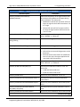
Purpose
Establish a long list or insert a sub-list to an existing list by inputting start power, stop power, frequency,
and number of list points.
Syntax
STATUS GT2400_EditPowerRangeByNumOfPts(
Parameter
const short position,
const short insertType,
const char listPath[],
const double startPower,
const double stopPower,
const double frequency,
const short numOfPts)
Description
position
Input: position in the list being edited, 0 < position ≤ current list length
insertType
Input: Insert Type:
0 = REPLACE
1 = INSERT BEFORE
2 = INSERT AFTER
(Note: if insertType = REPLACE, the existing list will be replaced with the newly
created list.)
listPath
Input: Complete path (path + list name) of the list
startPower
Input: Start power (in dBm)
stopPower
Input: Stop power (in dBm)
frequency
Input: Frequency for all list points (in MHz)
numOfPts
Input: Number of list points being created
Programming Manual, Part Number 34783, Rev A, July 2009
65
4. Programming Interfaces
4.3.3.49
Giga-tronics 2400/2500 Microwave Synthesizer Series
DLL Function; GT2400_EditListSyncOutOption
GT2400_EditListSyncOutOption
Purpose
Edit the sync out option for the current list.
Syntax
STATUS GT2400_EditListSyncOutOption(
const char listPath[],
const short syncOutOption)
Parameter
Description
listPath
Input: Complete path (path + list name) of the list being edited
syncOutOption
Input: Sync out option:
0 = No sync out
1 = Sync out at first list pt
2 = Sync out at last list pt
3 = Sync out at every list pt
66
Programming Manual, Part Number 34783, Rev A, July 2009
Giga-tronics 2400/2500 Microwave Synthesizer Series
4.3.3.50
4. Programming Interfaces
DLL Function; GT2400_EditRFOffTime
GT2400_EditRFOffTime
Purpose
Set the RF off time of a current list in PC RAM.
Syntax
STATUS GT2400_EditRFOffTime(
Parameter
RFOffTime
const double RFOffTime)
Description
Input: RF off time for all list points (in ms) 0.1ms ≤RFOffTime ≤ 1000ms
Programming Manual, Part Number 34783, Rev A, July 2009
67
4. Programming Interfaces
4.3.3.51
Giga-tronics 2400/2500 Microwave Synthesizer Series
DLL Function; GT2400_EditStepTime
GT2400_EditStepTime
Purpose
Set the step time of a current list in PC RAM.
Syntax
STATUS GT2400_EditStepTime(
Parameter
stepTime
68
const double stepTime)
Description
Input: Step time of the active list (in ms) 0.15ms ≤ stepTime ≤ 1000ms
Programming Manual, Part Number 34783, Rev A, July 2009
Giga-tronics 2400/2500 Microwave Synthesizer Series
4.3.3.52
4. Programming Interfaces
DLL Function; GT2400_EditSyncOutDelay
GT2400_EditSyncOutDelay
Purpose
Set the delay time for the sync out pulse generated.
Syntax
STATUS GT2400_EditSyncOutDelay(
Parameter
syncOutDelay
const double syncOutDelay)
Description
Input: Delay time of sync out pulse (in ms) 0.1ms ≤ syncOutDelay ≤ 1000ms
Programming Manual, Part Number 34783, Rev A, July 2009
69
4. Programming Interfaces
4.3.3.53
Giga-tronics 2400/2500 Microwave Synthesizer Series
DLL Function; GT2400_CloseAllLists
GT2400_CloseAllLists
Purpose
Remove all existing lists from PC RAM.
Syntax
STATUS GT2400_CloseAllLists( void)
70
Programming Manual, Part Number 34783, Rev A, July 2009
Giga-tronics 2400/2500 Microwave Synthesizer Series
4.3.3.54
4. Programming Interfaces
DLL Function; GT2400_CloseAList
GT2400_CloseAList
Purpose
Remove the selected list from PC RAM.
Syntax
STATUS GT2400_CloseAList(
Parameter
listPath
const char listPath[])
Description
Input: Complete path (path + list name) of the list being removed
Programming Manual, Part Number 34783, Rev A, July 2009
71
4. Programming Interfaces
4.3.3.55
Giga-tronics 2400/2500 Microwave Synthesizer Series
DLL Function; GT2400_DeleteAllListPoints
GT2400_DeleteAllListPoints
Purpose
Delete all points of a selected list. The contents of the memory are cleared but the memory is still
reserved for this list until the list is closed.
Syntax
STATUS GT2400_DeleteAllListPoints(
Parameter
listPath
72
const char listPath[])
Description
Input: Complete path (path + list name) of a list
Programming Manual, Part Number 34783, Rev A, July 2009
Giga-tronics 2400/2500 Microwave Synthesizer Series
4.3.3.56
4. Programming Interfaces
DLL Function; GT2400_DeleteAListPoint
GT2400_DeleteAListPoint
Purpose
Delete a point of a selected list from PC RAM.
Syntax
STATUS GT2400_ DeleteAListPoint(
Parameter
const char listPath[],
const short listPointIndex)
Description
listPath
Input: Complete path (path + list name) of the list whose point is deleted
listPointIndex
Input: Index of the list point being deleted
Programming Manual, Part Number 34783, Rev A, July 2009
73
4. Programming Interfaces
4.3.3.57
Giga-tronics 2400/2500 Microwave Synthesizer Series
DLL Function; GT2400_SetAMState
GT2400_SetAMState
Purpose
Set AM on/off.
Syntax
STATUS GT2400_SetAMState(
Parameter
const unsigned long instrumentHandle,
const unsigned short AMState)
Description
instrumentHandle
Input: The unique identification of the instrument
AMState
Input:
1 = AM is on
0 = AM is off
74
Programming Manual, Part Number 34783, Rev A, July 2009
Giga-tronics 2400/2500 Microwave Synthesizer Series
4.3.3.58
4. Programming Interfaces
DLL Function; GT2400_SetAMSource
GT2400_SetAMSource
Purpose
Set AM source to external/internal.
Syntax
STATUS GT2400_SetAMSource(
const unsigned long instrumentHandle,
const short AMSource)
Parameter
Description
instrumentHandle
Input: The unique identification of the instrument
AMSource
Output:
1= External source
0 = Internal source
Programming Manual, Part Number 34783, Rev A, July 2009
75
4. Programming Interfaces
4.3.3.59
Giga-tronics 2400/2500 Microwave Synthesizer Series
DLL Function; GT2400_SetAMExtSensitivity
GT2400_SetAMExtSensitivity
Purpose
Set AM sensitivity when AM source is external.
Syntax
STATUS GT2400_SetAMExtSensitivity(
Parameter
const unsigned long instrumentHandle,
double AMExtSensitivity)
Description
instrumentHandle
Input: The unique identification of the instrument
AMExtSensitivity
Input: AM sensitivity 0.0 < AMExtSensitivity < 95.0 (%/V)
76
Programming Manual, Part Number 34783, Rev A, July 2009
Giga-tronics 2400/2500 Microwave Synthesizer Series
4.3.3.60
4. Programming Interfaces
DLL Function; GT2400_SetAMIntWavefrm
GT2400_SetAMIntWavefrm
Purpose
Set the AM internal waveform.
Syntax
STATUS GT2400_SetAMIntWavefrm(
const unsigned long instrumentHandle,
const short AMIntWaveform)
Parameter
Description
instrumentHandle
Input: The unique identification of the instrument
AMIntWaveform
Input: AM internal waveform
1 = SINE
2 = SQUARE
3 = TRIANGLE
4 = RAMP
5 = NOISE
Programming Manual, Part Number 34783, Rev A, July 2009
77
4. Programming Interfaces
4.3.3.61
Giga-tronics 2400/2500 Microwave Synthesizer Series
DLL Function; GT2400_SetAMIntRate
GT2400_SetAMIntRate
Purpose
Set the AM internal rate.
Syntax
STATUS GT2400_SetAMIntRate(
Parameter
const unsigned long instrumentHandle,
const double AMIntRate)
Description
instrumentHandle
Input: The unique identification of the instrument
AMIntRate
Input: AM internal rate (in Hz) 0.01 Hz <= AMIntRate <= 1 MHz
78
Programming Manual, Part Number 34783, Rev A, July 2009
Giga-tronics 2400/2500 Microwave Synthesizer Series
4.3.3.62
4. Programming Interfaces
DLL Function; GT2400_SetAMIntDepth
GT2400_SetAMIntDepth
Purpose
Set the AM internal depth.
Syntax
STATUS GT2400_SetAMIntDepth(
Parameter
const unsigned long instrumentHandle,
const double AMIntDepth)
Description
instrumentHandle
Input: The unique identification of the instrument
AMIntDepth
Input: AM internal depth 0.0 <= AMIntDepth <= 95.0
Programming Manual, Part Number 34783, Rev A, July 2009
79
4. Programming Interfaces
4.3.3.63
Giga-tronics 2400/2500 Microwave Synthesizer Series
DLL Function; GT2400_SetFMState
GT2400_SetFMState
Purpose
Set the FM on/off.
Syntax
STATUS GT2400_SetFMState(
Parameter
const unsigned long instrumentHandle,
unsigned short FMState)
Description
instrumentHandle
Input: The unique identification of the instrument
FMState
Input:
1 = FM is on
0 = FM is off
80
Programming Manual, Part Number 34783, Rev A, July 2009
Giga-tronics 2400/2500 Microwave Synthesizer Series
4.3.3.64
4. Programming Interfaces
DLL Function; GT2400_SetFMSource
GT2400_SetFMSource
Purpose
Set the FM source to external/internal.
Syntax
STATUS GT2400_SetFMSource(
const unsigned long instrumentHandle,
const short FMSource)
Parameter
Description
instrumentHandle
Input: The unique identification of the instrument
FMSource
Input:
1 = External source
0 = Internal source
Programming Manual, Part Number 34783, Rev A, July 2009
81
4. Programming Interfaces
4.3.3.65
Giga-tronics 2400/2500 Microwave Synthesizer Series
DLL Function; GT2400_SetFMExtMode
GT2400_SetFMExtMode
Purpose
Set the FM source to external/internal.
Syntax
STATUS GT2400_SetFMExtMode(
Parameter
const unsigned long instrumentHandle,
const short FMExtMode)
Description
instrumentHandle
Input: The unique identification of the instrument
FMExtMode
Input:
1 = WIDE
0 = NARROW
82
Programming Manual, Part Number 34783, Rev A, July 2009
Giga-tronics 2400/2500 Microwave Synthesizer Series
4.3.3.66
4. Programming Interfaces
DLL Function; GT2400_SetFMExtSensitivity
GT2400_SetFMExtSensitivity
Purpose
Set the FM external sensitivity.
Syntax
STATUS GT2400_SetFMExtSensitivity(
const unsigned long instrumentHandle,
const double FMExtSensitivity,
const double freq)
Parameter
Description
instrumentHandle
Input: The unique identification of the instrument
FMExtSensitivity
Input: FM sensitivity (in Hz) (Please refer to FM sensitivity/deviation range table in
Appendix C)
freq
Input: CW frequency (in Hz)
Programming Manual, Part Number 34783, Rev A, July 2009
83
4. Programming Interfaces
4.3.3.67
Giga-tronics 2400/2500 Microwave Synthesizer Series
DLL Function; GT2400_SetFMIntWavefrm
GT2400_SetFMIntWavefrm
Purpose
Set the FM internal waveform.
Syntax
STATUS GT2400_SetFMIntWavefrm(
const unsigned long instrumentHandle,
const short FMIntWaveform)
Parameter
Description
instrumentHandle
Input: The unique identification of the instrument
FMIntWaveform
Input: FM internal waveform
1 = SINE
2 = SQUARE
3 = TRIANGLE
4 = RAMP
5 = NOISE
84
Programming Manual, Part Number 34783, Rev A, July 2009
Giga-tronics 2400/2500 Microwave Synthesizer Series
4.3.3.68
4. Programming Interfaces
DLL Function; GT2400_SetFMIntRate
GT2400_SetFMIntRate
Purpose
Set the FM internal rate.
Syntax
STATUS GT2400_SetFMIntRate(
Parameter
const unsigned long instrumentHandle,
const double FMIntRate)
Description
instrumentHandle
Input: The unique identification of the instrument
FMIntRate
Input: FM internal rate (in Hz) 0.1 Hz <= FMIntRate <= 1 MHz
Programming Manual, Part Number 34783, Rev A, July 2009
85
4. Programming Interfaces
4.3.3.69
Giga-tronics 2400/2500 Microwave Synthesizer Series
DLL Function; GT2400_SetFMIntDev
GT2400_SetFMIntDev
Purpose
Set the FM internal deviation.
Syntax
STATUS GT2400_SetFMIntDev(
const unsigned long instrumentHandle,
const double FMIntDeviation,
const double freq)
Parameter
Description
instrumentHandle
Input: The unique identification of the instrument
FMIntDeviation
Input: FM deviation (in Hz) (Please refer to FM sensitivity/deviation range table in
Appendix C)
freq
Input: CW frequency (in Hz)
86
Programming Manual, Part Number 34783, Rev A, July 2009
Giga-tronics 2400/2500 Microwave Synthesizer Series
4.3.3.70
4. Programming Interfaces
DLL Function; GT2400_SetPMState
GT2400_SetPMState
Purpose
Set the PM on/off.
Syntax
STATUS GT2400_SetPMState(
Parameter
const unsigned long instrumentHandle,
const unsigned short PMState)
Description
instrumentHandle
Input: The unique identification of the instrument
PMState
Input:
1 = PM is on
0 = PM is off
Programming Manual, Part Number 34783, Rev A, July 2009
87
4. Programming Interfaces
4.3.3.71
Giga-tronics 2400/2500 Microwave Synthesizer Series
DLL Function; GT2400_SetPMSource
GT2400_SetPMSource
Purpose
Set the PM state to internal or external.
Syntax
STATUS GT2400_SetPMSource(
const unsigned long instrumentHandle,
const short PMSource)
Parameter
Description
instrumentHandle
Input: The unique identification of the instrument
PMSource
Input:
1 = external source
0 = internal source
88
Programming Manual, Part Number 34783, Rev A, July 2009
Giga-tronics 2400/2500 Microwave Synthesizer Series
4.3.3.72
4. Programming Interfaces
DLL Function; GT2400_SetPMExtPolarity
GT2400_SetPMExtPolarity
Purpose
Set the PM state to internal or external.
Syntax
STATUS GT2400_SetPMExtPolarity (
const unsigned long instrumentHandle,
const short PMExtPolarity)
Parameter
Description
instrumentHandle
Input: The unique identification of the instrument
PMExtPolarity
Input:
1 = active low
0 = active high
Programming Manual, Part Number 34783, Rev A, July 2009
89
4. Programming Interfaces
4.3.3.73
Giga-tronics 2400/2500 Microwave Synthesizer Series
DLL Function; GT2400_SetPMMode
GT2400_SetPMMode
Purpose
Set the PM internal control mode.
Syntax
STATUS GT2400_SetPMMode(
const unsigned long instrumentHandle,
const short mode)
Parameter
Description
instrumentHandle
Input: The unique identification of the instrument
mode
Input: PM operation mode
0 = PM OFF
1 = Triggered mode
2 = Continuous mode
3 = Gated mode
90
Programming Manual, Part Number 34783, Rev A, July 2009
Giga-tronics 2400/2500 Microwave Synthesizer Series
4.3.3.74
4. Programming Interfaces
DLL Function; GT2400_SetPMIntTrigPolarity
GT2400_SetPMIntTrigPolarity
Purpose
Set the PM trigger polarity for internal source.
Syntax
STATUS GT2400_SetPMIntTrigPolarity(
Parameter
const unsigned long instrumentHandle,
const short PMIntPolarity)
Description
instrumentHandle
Input: The unique identification of the instrument
PMIntPolarity
Input: PM trigger polarity for internal source
1 = falling
0 = rising
Programming Manual, Part Number 34783, Rev A, July 2009
91
4. Programming Interfaces
4.3.3.75
Giga-tronics 2400/2500 Microwave Synthesizer Series
DLL Function; GT2400_SetPMIntWidth
GT2400_SetPMIntWidth
Purpose
Set the PM waveform for internal source.
Syntax
STATUS GT2400_SetPMIntWidth(
Parameter
const unsigned long instrumentHandle,
const double PMIntWidth)
Description
instrumentHandle
Input: The unique identification of the instrument
PMIntWidth
Input: PM pulse width (in usec) 0.1 usec <= PMIntWidth <= 10 msec
92
Programming Manual, Part Number 34783, Rev A, July 2009
Giga-tronics 2400/2500 Microwave Synthesizer Series
4.3.3.76
4. Programming Interfaces
DLL Function; GT2400_SetPMIntRFPulseDelay
GT2400_SetPMIntRFPulseDelay
Purpose
Set the PM RF pulse delay for internal source.
Syntax
STATUS GT2400_SetPMIntRFPulseDelay (
Parameter
const unsigned long instrumentHandle,
const double PMIntRFPulseDelay);
Description
instrumentHandle
Input: The unique identification of the instrument
PMIntRFPulseDelay
Input: PM RF pulse delay (in usec) 0.1 usec <= PMIntRFPulseDelay <= 1.0 sec
Programming Manual, Part Number 34783, Rev A, July 2009
93
4. Programming Interfaces
4.3.3.77
Giga-tronics 2400/2500 Microwave Synthesizer Series
DLL Function; GT2400_SetPMIntPRI
GT2400_SetPMIntPRI
Purpose
Set the PM trigger PRI (Pulse Repetition Interval) for internal source.
Syntax
STATUS GT2400_SetPMIntPRI(
const unsigned long instrumentHandle,
const short mode,
const double PMIntPRI);
Parameter
Description
instrumentHandle
Input: The unique identification of the instrument
mode
Input: PM operation mode
0 = PM OFF
1 = Triggered mode
2 = Continuous mode
3 = Gated mode
PMIntPRI
Input: PM PRI (in usec)
0.2 usec <= PMIntPRI <= 1.0 sec
94
Programming Manual, Part Number 34783, Rev A, July 2009
Giga-tronics 2400/2500 Microwave Synthesizer Series
4.3.3.78
4. Programming Interfaces
DLL Function; GT2400_SetPMIntSyncDelay
GT2400_SetPMIntSyncDelay
Purpose
Set the PM sync out delay for internal source.
Syntax
STATUS GT2400_SetPMIntSyncDelay (
Parameter
const unsigned long instrumentHandle,
const double PMIntSyncDelay);
Description
instrumentHandle
Input: The unique identification of the instrument
PMIntSyncDelay
Input: PM sync out delay (in usec) 0 usec <= PMIntSyncDelay <= PRI – 0.1 usec
Programming Manual, Part Number 34783, Rev A, July 2009
95
4. Programming Interfaces
Giga-tronics 2400/2500 Microwave Synthesizer Series
4.4 SCPI Command Set
The SCPI format and commands supported by 2400/2500 is explained in this section.
4.4.1 SCPI Command Format
SCPI conformance requires adherence to a strict syntax structure. The typographic conventions
employed in the tables within each of the subsystem descriptions under “SCPI Command Subsystems”,
below, are summarized in this section.
Case Sensitivity SCPI commands are not case-sensitive and can be entered in either uppercase or
lowercase characters.
Abbreviating Commands
•
Letters noted in upper case.
•
If entering more than the required letters, the entire command must be entered. For example, if the
command syntax is shown as INITiate, either INIT, init, INITIATE, or initiate can be used.
Optional Commands If the syntax shows a portion of a SCPI command in square brackets, that portion is
an implied command which can be omitted. An implied command is the default command among the
commands available at its level. For example, in the case of the command INITiate:[IMMediate], the
immediate mode is the default mode, therefore, entering INIT has the same effect as entering INIT:IMM.
NOTE: The square brackets [ ] themselves are not actually part of the command; hence, they should be
omitted even if the optional command is entered.
Queries Most SCPI commands have an accompanying query form that can be sent to cause the
instrument to return the current state of the parameter setting. For example, the query form of the
TRIGger: SOURce BUS|EXTernal command is TRIGger:SOURce? Some SCPI commands are events that
cause something to happen at a particular time but do not create a setting or value to be checked
afterwards. Consequently, they have no query form.
96
Programming Manual, Part Number 34783, Rev A, July 2009
Giga-tronics 2400/2500 Microwave Synthesizer Series
4. Programming Interfaces
4.4.2 SCPI Commands
The 2400/2500 SCPI commands are divided into subsystems. The following sections describe the
2400/2500 SCPI commands, and are organized according to subsystems.
4.4.2.1 SCPI Commands; Output Subsystem
Table 8
Output Subsystem SCPI Commands
Command Syntax
Description
OUTPut[:STATe] ON|OFF|1|0
Turns the signal at the RF OUT connector on or off.
OUTPut[:STATe]?
Queries the RF OUTPUT state. The return value is as
follows:
1 The signal at the RF OUT connector is currently on.
0 The signal at the RF OUT connector is currently off.
4.4.2.2 SCPI Commands; Source Subsystem – CW Mode
All commands in the Source subsystem begin with [SOURce]; however, [SOURce] is the default
command, which is optional.
Table 9
Source Subsystem – CW Mode SCPI Commands
Command Syntax
Description
[SOURce]:FREQuency[:CW|:FIXed] <freq> [HZ |
KHZ | MHZ | GHZ]
Sets CW frequency to the value specified by
<freq>. The units are assumed to be in Hertz if no
unit designator is supplied.
[SOURce]:FREQuency[:CW|:FIXed]?
Queries the current CW frequency. The value
returned is in Hz.
[SOURce]:MODE CW|FIXed|LIST|FSWEep
|PSWEep
Sets the operational mode of the synthesizer:
[SOURce]:MODE?
•
CW or FIXed is used to set the source to
output a non-swept signal.
•
LIST is used to set the source to use LIST mode.
•
FSWEep is used to set the source to frequency
sweep.
•
PSWEep is used to set the source to power
sweep.
Queries the current operating mode of the
instrument.
Programming Manual, Part Number 34783, Rev A, July 2009
97
4. Programming Interfaces
Table 9
Giga-tronics 2400/2500 Microwave Synthesizer Series
Source Subsystem – CW Mode SCPI Commands
Command Syntax
Description
[SOURce]:PHASe:[ADJust:] n (RADians|DEGrees)
Sets the relative phase of the output signal. The
default units are in radians where the range is -2 pi
< n < +2 pi. The command also accepts phase
offsets in degrees where the range is -360° < n <
+360°. Radians are the default units if no units are
specified. Changing frequency automatically resets
the phase offset to zero.
[SOURce]:POWer:ALC:SOURce INTernal
|DIODe|PMETer|DPOSitive
Selects the source of the feedback signal for the
ALC. The DIODe parameter assumes a negative
crystal detector is used. DPOSitive allows for the
use of a positive crystal detector.
[SOURce]:POWer:ATTenuation:AUTO ON|OFF
Sets the Attenuator to Auto (ON) or Manual (OFF).
[SOURce]:POWer:ATTenuation
0|10|20|30|40|50|60|70|80|90
Sets the Attenuator to the specified fixed (manual)
value.
[SOURce]:POWer:ATTenuation?
Queries the Attenuator setting.
[SOURce]:POWer:[:LEVel:][IMMediate:]
[AMPLitude:] <level> (DM | DBM |
dBV)|MAXimum|MINimum
Sets the CW power level to the value specified by
<level>. The units are defined as DM, DBM, or dBV.
[SOURce]:POWer:[:LEVel|:IMMediate|
:AMPLitude]?
Queries the CW power level The value returned is
in dBm.
[SOURce]:ROSCillator:SOURce?
Queries the source of the reference oscillator. The
return value is as follows:
INT The internal oscillator is being used as the
reference.
EXT A signal at the EXT REF IN connector is being
used as the reference.
98
Programming Manual, Part Number 34783, Rev A, July 2009
Giga-tronics 2400/2500 Microwave Synthesizer Series
4. Programming Interfaces
4.4.2.3 SCPI Commands; Source Subsystem – Power
Table 10
Source Subsystem – Power SCPI Commands
Command Syntax
Description
[SOURce]:POWer:ALC:SOURce
INTernal|DIODe|PMETer|DPOSitive
Selects the source of the feedback signal for the ALC. The
DIODe parameter assumes a negative crystal detector is
used. DPOSitive allows for the use of a positive crystal
detector.
[SOURce:]POWer:ALC:SOURce?
Queries the type of leveling for output power automatic
level control
[SOURce:]POWer:ATTenuation:AUTO?
Queries attenuation mode: auto or manual
[SOURce:]POWer:CENTer d
Sets the center of power
[SOURce:]POWer:CENTer?
Queries the center of power
[SOURce:]POWer[:LEVel][:IMMediate][:A
MPLitude:]STEP[:INCRement] d (DB)
Selects the increment value for the Synthesizer output
power level
[SOURce:]POWer[:LEVel][:IMMediate][:A
MPLitude:]STEP[:INCRement]?
Query the increment value for the Synthesizer output
power level
4.4.2.4 SCPI Commands; Source Subsystem – Correction
Table 11
Source Subsystem – Correction SCPI Commands
Command Syntax
Description
[SOURce]:CORRection:LOSS <offset> [DB]
Sets the power offset to the value specified by <offset>. The
units are dB.
[SOURce]:CORRection:LOSS?
Queries the power offset. The value returned is in dB.
[SOURce]:CORRection:SLOPe <slope>
Sets the power slope to the value specified by <slope>. The
units are dB/GHz.
[SOURce]:CORRection:SLOPe?
Queries the power slope. The value returned is in dB/GHz
Programming Manual, Part Number 34783, Rev A, July 2009
99
4. Programming Interfaces
Giga-tronics 2400/2500 Microwave Synthesizer Series
4.4.2.5 SCPI Commands; Source Subsystem – List Mode
Table 12
Source Subsystem – List Mode SCPI Commands
Command Syntax
Description
[SOURce]:LIST:DIRection UP|DOWN
Sets the direction of a list when it is run. If UP is
set, the list will run from start to end. If DOWN is
set, the list will run from end to start. The default
is UP.
[SOURce]:LIST:DIRection?
Queries the currently set list run direction. The
return value is as follows:
UP The list is set to run from start to end.
DOWN The list is set to run from end to start.
[SOURce]:LIST:DWELl <t1>,<t2>,……,<tn>
Specifies the dwell point times
(<t1>,<t2>,……,<tn>) of the list set, the dwell point
times are delimited by commas. The 2400/2500
list dwell setting is global for all list points. The first
dwell time parameter applies to all subsequent
points. Setting additional dwell times is optional.
The units are seconds.
[SOURce]:LIST:DWELl:POINts?
Queries the number of points in the dwell time list.
[SOURce]:LIST:FREQuency <f1>,<f2>,<f3>,……,<fn>
Specifies the frequency points
(<f1>,<f2>,<f3>,……,<fn>) of the list set. The
frequency points are delimited by commas.
[SOURce]:LIST:FREQuency:POINts?
Queries the number of points currently in the
frequency list.
[SOURce]:LIST:POWer <p1>,<p2>,<p3>,……,<pn>
Specifies the power points
(<p1>,<p2>,<p3>,……,<pn>) of the list set. The
power points are delimited by commas.
[SOURce]:LIST:POWer:POINts?
Returns the number of points currently in the
power list
[SOURce]:LIST:PRECompute
Converts (pre-computes) the raw data of list saved
NVRAM into DSP format. Return 0 when done.
Continued next page
100
Programming Manual, Part Number 34783, Rev A, July 2009
Giga-tronics 2400/2500 Microwave Synthesizer Series
Table 12
4. Programming Interfaces
Source Subsystem – List Mode SCPI Commands
Command Syntax
[SOURce]:LIST:REPeat
SWEEp|STEP|CONTinuous
Description
Sets the repeat mode for the current list. The
choices are:
•
SWEEp - Upon triggering, the entire list is
executed from the beginning, then execution
stops.
•
STEP - Upon triggering, the current list point is
executed, then execution stops. The next
trigger executes the next point in the list. The
list’s first point is considered to be the initial
current point, and the point following the list’s
final point.
•
CONTinuous - The entire list repeats
indefinitely.
[SOURce]:LIST:REPeat?
Queries the repeat mode of the current list
[SOURce]:LIST:SEQuence
<m1>,<m2>,<m3>,….,<mn>
Defines a sequence for stepping through the
existing list when [SOURce]:LIST:SEQuence:AUTO
is set to OFF. The points specified in this command
(<m1>,<m2>,<m3>,….,<mn>) are indexes into a
new sub-list, and only points in this sub-list will be
triggered. For example, if one of the indexes
defined with this command is 3, then the third
point in the frequency, dwell, and power lists will
be sequenced.
[SOURce]:LIST:SEQuence:POINts?
Queries the number of points in the sequence list
[SOURce]:LIST:SEQuence:AUTO ON|OFF
Sets list sequence AUTO mode. The choices are:
•
ON The list sequence set with the
[SOURce]:LIST:SEQuence command will not
take effect, so all list points will run when
triggered.
•
OFF The list will run only the points set with
the [SOURce]:LIST:SEQuence command. The
default is ON. NOTE: This command is also
used to change the 2400/2500 mode from CW
or Ramp to List mode. Example: LIST: SEQ:
AUTO ON switches to List Mode
Continued next page
Programming Manual, Part Number 34783, Rev A, July 2009
101
4. Programming Interfaces
Table 12
Giga-tronics 2400/2500 Microwave Synthesizer Series
Source Subsystem – List Mode SCPI Commands
Command Syntax
Description
[SOURce]:LIST:SYNC <sync>
Sets sync out option to <sync>. The sync out
option determines how a pulse is emitted from the
SYNC OUT connector during List operation. The
choices are:
•
0 No pulses are emitted from the SYNC OUT
connector during List operation.
•
1 A pulse is emitted from the SYNC OUT
connector when the first list point is executed.
•
2 A pulse is emitted from the SYNC OUT
connector when the last list point is executed.
•
3 A pulse is emitted from the SYNC OUT
connector when each point in the list is
executed.
[SOURce:]LIST:DELete:LIST <list>
Clear all the points from list <list>
[SOURce:]LIST:POWer:RANGe:ADD <list> <point>
Insert the power list range to the list <list> after
point number <point>
[SOURce:]LIST: POWer:RANGe:DWELl <value>
[S|MS|US]
Set the list dwell time for the list range to <value>
[SOURce:]LIST: POWer:RANGe:FREQuency <value>
[HZ|KZ|KHZ|MZ|MHZ|GZ|GHZ]
Set the frequency for the list range to <value>
[SOURce:]LIST: POWer:RANGe:STARt <value>
[DM|DBM]
Set the start power for the list range to <value>
[SOURce:]LIST: POWer:RANGe:STEP <value> [DB|
DBM]
Set the step power for the list range to <value>
[SOURce:]LIST: POWer:RANGe:STOP <value>
[DM|DBM]
Set the stop power for the list range to <value>
[SOURce:]LIST:RANGe:ADD <list> <point>
Insert the frequency list range to the list <list>
after point number <point>
[SOURce:]LIST:RANGe:DWELl <value> [S|MS|US]
Set the list dwell time for the list range to <value>
[SOURce:]LIST:RANGe:POWer <value> [DM|DBM]
Set the power output for the list range to <value>
[SOURce:]LIST:RANGe:STARt <value>
[HZ|KZ|KHZ|MZ|MHZ|GZ|GHZ]
Set the start frequency for the list range to <value>
[SOURce:]LIST:RANGe:STEP <value>
(HZ|KZ|KHZ|MZ|MHZ|GZ|GHZ)
Set the step frequency for the list range to <value>
Continued next page
102
Programming Manual, Part Number 34783, Rev A, July 2009
Giga-tronics 2400/2500 Microwave Synthesizer Series
Table 12
4. Programming Interfaces
Source Subsystem – List Mode SCPI Commands
Command Syntax
Description
[SOURce:]LIST:RANGe:STOP <value>
(HZ|KZ|KHZ|MZ|MHZ|GZ|GHZ)
Set the stop frequency for the range to <value>
[SOURce:]LIST:SEQuence:AUTO?
Query list sequence AUTO mode
[SOURce:]LIST:SYNCout <value>
Generate a pulse at a rear panel BNC output
according to <value>
0-none
1-start
2-end
3-all list points
[SOURce:]LIST:SYNCout?
Query the sync out “mode”
[SOURce:]LIST:SYNCout:DELay <value>
Set Sync out delay in uSec.
Min is 50
Max is 1000000 (1 second)
[SOURce:]LIST:SYNCout:DELay?
Query the sync output delay
Programming Manual, Part Number 34783, Rev A, July 2009
103
4. Programming Interfaces
Giga-tronics 2400/2500 Microwave Synthesizer Series
4.4.2.6 SCPI Commands; Status Subsystem
Table 13
Status Subsystem SCPI Commands
Command Syntax
Description
STATus:OPERation:CONDition?
Queries the contents of the Operation Condition
register
STATus:OPERation:ENABle n
Sets the contents of the Operation Event Enable
register
STATus:OPERation:ENABle?
Queries the contents of the Operation Event
Enable register
STATus:OPERation: [:EVENt]?
Queries the contents of the Operation Event
register
STATus:OPERation:NTRansition n
Defines which bits in the Operation Condition
register will set the corresponding bit in the
Operation Event register on a one to zero state
change.
STATus:OPERation:NTRansition?
Queries which bits in the Operation Condition
register will set the corresponding bit in the
Operation Event register on a one to zero state
change.
STATus:OPERation: PTRansition n
Defines which bits in the Operation Condition
register will set the corresponding bit in the
Operation Event register on a zero to one state
change.
STATus:OPERation: PTRansition?
Queries which bits in the Operation Condition
register will set the corresponding bit in the
Operation Event register on a zero to one state
change.
STATus:PRESet
Sets several Operation and Questionable registers
to known states
STATus:QUEStionable:CONDition?
Returns the value of the Questionable Status
Condition Register. The value returned is a decimal
value representing the current state of the
register.
STATus:QUEStionable:ENABle <ques>
Sets the Questionable Status Enable Register.
Range of <ques> is 0 - 65535
Continued next page
104
Programming Manual, Part Number 34783, Rev A, July 2009
Giga-tronics 2400/2500 Microwave Synthesizer Series
Table 13
4. Programming Interfaces
Status Subsystem SCPI Commands
Command Syntax
Description
STATus:QUEStionable: ENABle?
Queries the contents of the Questionable Event
Enable register
STATus:QUEStionable: [:EVENt]?
Returns the contents of the Questionable Event
register
STATus:QUEStionable: NTRansition n
Defines which bits in the Questionable Condition
register will set the corresponding bit in the
Questionable Event register on a one to zero state
change
STATus:QUEStionable: NTRansition?
Queries which bits in the Questionable Condition
register will set the corresponding bit in the
Questionable Event register on a one to zero state
change
STATus:QUEStionable: PTRansition n
Defines which bits in the Questionable Condition
register will set the corresponding bit in the
Questionable Event register on a zero to one state
change
STATus:QUEStionable: PTRansition?
Queries which bits in the Questionable Condition
register will set the corresponding bit in the
Questionable Event register on a zero to one state
change
Programming Manual, Part Number 34783, Rev A, July 2009
105
4. Programming Interfaces
Giga-tronics 2400/2500 Microwave Synthesizer Series
4.4.2.7 SCPI Commands; System Subsystem
Table 14
System Subsystem SCPI Commands
Command Syntax
Description
SYSTem:COMMunicate:GPIB[:SELF]:ADDRess
<address>|MAXimum|MINimum
Sets the instrument's GPIB address. The choices
are as follows: <address> Any integer between 1
and 30.
MAXimum Sets the GPIB address to 30.
MINimum Sets the GPIB address to 1.
SYSTem:COMMunicate:GPIB[:SELF]:ADDRess?
Queries the instrument's GPIB address.
SYSTem:COMMunicate:SERial:BAUD <rate>
Sets the RS-232 interface baud rate. The supported
values for <rate> are 9600, 19200, 38400, and
115200.
SYSTem:COMMunicate:SERial:BAUD?
Queries the current RS-232 interface baud rate.
SYSTem:COMMunicate:SERial:BITS <bits>
Sets the number of RS-232 interface data bits. The
supported values for <bits> are 7 and 8.
SYSTem:COMMunicate:SERial:BITS?
Queries the number of RS-232 interface data bits.
SYSTem:COMMunicate:SERial:PARity[:T YPE] EVEN
| ODD | NONE
Sets the RS-232 interface parity type. The choices
are as follows: EVEN Selects even parity. ODD
Selects odd parity. NONE Parity is not used.
SYSTem:COMMunicate:SERial:PARity?
Queries the RS-232 interface parity setting.
SYSTem:COMMunicate:SERial:SBITS <sbits>
Sets the number of RS-232 interface stop bits. The
supported values for <sbits> are 1 and 2.
SYSTem:COMMunicate:SERial:SBITS?
Queries the number of RS-232 interface stop bits.
SYSTem:ERRor[:NEXT]?
Queries the next error in the instrument’s
error/event queue. If the error/event queue is
empty, “0, No Error” is returned.
See Table 59 in Appendix A for a summary of
available error messages
SYSTem:LANGuage NATive
Switches from the SCPI command set to the native
(GT12000) command set.
SYSTem:LANGuage:NATive <native_cmd>
Issues the native (GT12000) syntax command
specified by <native_cmd> from within SCPI
without leaving the SCPI syntax.
Continued next page
106
Programming Manual, Part Number 34783, Rev A, July 2009
Giga-tronics 2400/2500 Microwave Synthesizer Series
Table 14
4. Programming Interfaces
System Subsystem SCPI Commands
Command Syntax
Description
SYSTem:PRESet
Sets device-specific functions to a known state
that is independent of the past-use history of the
device. The command does not reset any part of
the status reporting system. (Same as the *RST
command.)
SYSTem:VERSion?
Queries the SCPI version to which the instrument
applies. The response is in the form YYYY.V where
YYYY is the year-version and V is the revision
number within that year.
SYSTem:OPENlooppm ON|OFF
Controls open loop PM
SYSTem:OPENlooppm?
Queries Controls open loop PM
SYSTem:TIMer?
Query real-time operating system timer
Programming Manual, Part Number 34783, Rev A, July 2009
107
4. Programming Interfaces
Giga-tronics 2400/2500 Microwave Synthesizer Series
4.4.2.8 SCPI Commands; Trigger Subsystem
Table 15
Trigger Subsystem SCPI Commands
Command Syntax
Description
TRIGger[:IMMediate]
Initiates an immediate sweep cycle in List mode. If
Repeat Type is set to either single step or single
sweep, then the sweep returns to IDLE when
complete. (Same as a *TRG, that is a single
instrument trigger, as opposed to a
GroupExecuteTrigger.)
TRIGger:SOURce BUS|EXTernal
Selects the trigger source for List mode. The
sources are:
TRIGger:SOURce?
108
•
BUS Sets the trigger source to GPIB/GET.
•
EXTernalSets the trigger source to BNC.
(Trigger commands do not function when
TRIGger:SOURce is set to EXT).
Queries the trigger source for List mode. The
return value is as follows:
•
BUS The trigger source is set to GPIB/GET.
•
EXTernalThe trigger source is set to BNC. If not
set, NOT IN SWEEP MODE is returned.
Programming Manual, Part Number 34783, Rev A, July 2009
Giga-tronics 2400/2500 Microwave Synthesizer Series
4. Programming Interfaces
4.4.2.9 SCPI Commands; Source Subsystem – Ramp Sweep
Table 16
Source Subsystem - Ramp Sweep SCPI Commands
Command Syntax
Description
[SOURce]:FREQuency:STARt <f_start> [HZ | KHZ |
MHZ | GHZ]
Sets the ramp start frequency to the value
specified by <f_start>. Hertz is assumed as the
units if units are not specified.
The start frequency must be set less than the stop
frequency. If this rule is violated, the start and stop
frequencies are set to the same value.
[SOURce]:FREQuency:STARt?
Queries the ramp start frequency. The return value
is in Hertz.
[SOURce]:FREQuency:STOP <f_stop> [HZ | KHZ |
MHZ | GHZ]
Sets the ramp stop frequency to the value
specified by <f_stop>. Hertz is assumed as the
units if no units is specified. The start frequency
must be set less than the stop frequency. If this
rule is violated, the start and stop frequencies are
set to the same value.
[SOURce]:FREQuency:STOP?
Queries the ramp stop frequency. The return value
is in Hertz.
[SOURce]:SWEep: TIME <time>
Sets the sweep time for ramp sweep to the value
specified by <time>. The units are seconds.
[SOURce]:SWEep:TIME?
Queries the sweep time for ramp sweep. The
return value is in seconds.
[SOURce]:POWer:STARt d (DM | DBM | dBV)
Sets the ramp sweep start power level. The
assumed units are defined as DM, DBM, or dBV.
[SOURce]:POWer:STARt?
Queries the ramp start power. The return value is
in dBm.
[SOURce]:POWer:STOP d (DM | DBM | dBV)
Sets the ramp sweep stop power level. The
assumed units are defined as DM, DBM, or dBV.
[SOURce]:POWer:STOP?
Queries the ramp stop power. The return value is
in dBm.
[SOURce]:POWer:SPAN d
Sets the amplitude span
[SOURce]:POWer:SPAN?
Queries the amplitude span
Programming Manual, Part Number 34783, Rev A, July 2009
109
4. Programming Interfaces
4.4.2.10
Giga-tronics 2400/2500 Microwave Synthesizer Series
SCPI Commands; Source Subsystem – Modulation
All commands in the Source subsystem begin with [SOURce], however, [SOURce] is the default
command, and therefore it is optional.
Table 17
Source Subsystem – Modulation SCPI Commands
Command Syntax
Description
[SOURce]:AM:DEPTh <am_depth>
Sets the internal amplitude modulation depth to a
percentage value as specified by <am_depth>.
[SOURce]:AM:DEPTh?
Queries the internal amplitude modulation depth.
The return value is in percent.
[SOURce]:AM:INTernal:FREQuency <am_freq> [HZ
| KHZ | MHZ | GHZ]
Sets the rate of the internal amplitude modulation
generator to the value specified by <am_feq>.
Hertz is assumed if no unit is specified.
[SOURce]:AM:INTernal:FREQuency?
Queries the rate of the internal amplitude
modulation generator. The return value is in Hertz
(Not available with Option 17 or 17A).
[SOURce]:AM:INTernal:FUNCtion:SHAP e
OFF|SINE|SQUare|TRIangle|PRaMP|NOI Se
Sets the shape of the internal amplitude
modulation generator waveform. The choices are:
•
OFF Turns the internal amplitude modulation
generator off.
•
SINE Sets the internal amplitude modulation
generator waveform to sine wave.
•
SQUare Sets the internal amplitude
modulation generator waveform to square
wave.
•
TRIangle Sets the internal amplitude
modulation generator waveform to triangle
wave.
•
PraMP Sets the internal amplitude modulation
generator waveform to a positive-going ramp.
•
NOIse Selects the internal noise generator as
the amplitude modulation generator.
[SOURce]:AM:INTernal:FUNCtion:SHAPe?
Queries the shape of the internal amplitude
modulation generator waveform. Returns: "Off",
"Sine", "Square", "Triangle", "Pos Ramp", or
"Noise".
[SOURce]:AM:SCALing <am_scaling>
Sets the external amplitude modulation scaling to
a percentage per volt value as specified by
<am_scaling>.
Continued next page
110
Programming Manual, Part Number 34783, Rev A, July 2009
Giga-tronics 2400/2500 Microwave Synthesizer Series
Table 17
4. Programming Interfaces
Source Subsystem – Modulation SCPI Commands
Command Syntax
Description
[SOURce]:AM:SCALing?
Queries the external amplitude modulation
scaling. Return value is a percentage per volt.
[SOURce]:AM:SOURce INTernal|EXTernal
Sets the amplitude modulation source. The choices
are:
•
INTernal Sets the internal AM generator as the
AM source.
•
EXTernal Selects external AM. The modulation
source in this case is the signal applied at the
rear-panel AM IN connector.
[SOURce]:AM:SOURce?
Queries the amplitude modulation source. Returns
"INTernal" or "EXTernal"
[SOURce]:AM:STATe ON|OFF|1|0
Sets amplitude modulation mode on or off. The
choices are as follows:
[SOURce]:AM:STATe?
•
1|ON Sets AM mode to on.
•
0|OFF Sets AM mode to off.
Queries the state of amplitude modulation mode.
The return values is are follows:
•
1 AM mode is currently on.
•
0 AM mode is currently off.
[SOURce]:AM:SENSitivity d
Sets the modulation depth of an AM signal.
[SOURce]:AM:SENSitivity?
Queries the modulation depth of an AM signal.
[SOURce]:FM:BANDwidth NARRow|WIDE
Sets the Frequency Modulation bandwidth to
Narrow or Wide.
[SOURce]:FM:BANDwidth?
Queries the Frequency Modulation bandwidth.
Return “Narrow” or “Wide”.
[SOURce]:FM[:DEViation] <fm_dev> [HZ | KHZ |
MHZ | GHZ]
Sets the internal frequency modulation deviation
to the value specified by <fm_dev>. Hertz is
assumed for the units if no units is specified.
[SOURce]:FM[:DEViation]?
Queries the internal frequency modulation
deviation that is currently set. The return value is
in Hertz.
[SOURce]:FM:INTernal:FREQuency <fm_freq> [HZ
| KHZ | MHZ | GHZ]
Sets the rate of the internal frequency modulation
generator to the value specified by <fm_freq>.
Hertz is assumed for the units if units are not
specified.
Continued next page
Programming Manual, Part Number 34783, Rev A, July 2009
111
4. Programming Interfaces
Table 17
Giga-tronics 2400/2500 Microwave Synthesizer Series
Source Subsystem – Modulation SCPI Commands
Command Syntax
Description
[SOURce]:FM:INTernal:FREQuency?
Queries the current rate of the internal frequency
modulation generator. The return value is in Hertz.
[SOURce]:FM:INTernal:FUNCtion:SHAPe
OFF|SINE|SQUare|TRIangle|PRaMP
Sets the shape of the internal frequency
modulation generator waveform. The choices are:
•
OFF Turns the internal frequency modulation
generator off.
•
SINE Sets the internal frequency modulation
generator waveform to sine wave.
•
SQUare Sets the internal frequency
modulation generator waveform to square
wave.
•
TRIangle Sets the internal frequency
modulation generator waveform to triangle
wave.
•
PRaMP Sets the internal frequency modulation
generator waveform to a positive-going ramp.
[SOURce]:FM:INTernal:FUNCtion:SHAPe ?
Queries the shape of the internal frequency
modulation generator waveform. Returns: "Off",
"Sine", "Square", "Triangle", or "Pos Ramp".
[SOURce]:FM:SENSitivity <fm_sens>
Sets the Frequency Modulation external sensitivity
to the value specified by <fm_sens>. The value is in
Hertz per volt.
[SOURce]:FM:SENSitivity?
Queries the frequency modulation external
sensitivity. The return value is in Hertz per volt.
[SOURce]:FM:SOURce EXTernal| INTernal|DC
Sets the frequency modulation source. The choices
are:
[SOURce]:FM:SOURce?
•
INTernal Sets the internal FM generator as the
PM source.
•
EXTernal Selects external FM. The modulation
source in this case is the signal applied at the
rear-panel FM/φM IN connector.
•
DC Maximum deviation for DC mode is 125
kHz for ±1 volt external input from 500 MHz to
maximum frequency of the instrument.
Queries the phase modulation source. Returns
either "Internal" or "External".
Continued next page
112
Programming Manual, Part Number 34783, Rev A, July 2009
Giga-tronics 2400/2500 Microwave Synthesizer Series
Table 17
4. Programming Interfaces
Source Subsystem – Modulation SCPI Commands
Command Syntax
[SOURce]:FM:STATe ON|OFF|1|0
[SOURce]:FM:STATe?
Description
Sets the frequency modulation mode on or off.
The choices are:
•
1|ON Sets FM mode to on.
•
0|OFF Sets FM mode to off.
Queries the frequency modulation mode. The
returned values are:
•
1 FM mode is currently on.
•
0 FM mode is currently off.
[SOURce]:FM:COUPling AC|DC
Sets the coupling between the modulator and the
modulating signal
[SOURce]:FM:COUPling ?
Queries the coupling between the modulator and
the modulating signal
[SOURce]:PM[:DEViation] <fm_dev> [HZ | KHZ |
MHZ | GHZ]
Sets the internal phase modulation deviation to
the value specified by <fm_dev>. Hertz is assumed
for the units if unit is not specified.
[SOURce]:PM[:DEViation]?
Queries the internal Phase Modulation deviation
that is currently set. The return value is in Hertz.
[SOURce]:PM:INTernal:FREQuency <fm_freq> [HZ
| KHZ | MHZ | GHZ]
Sets the rate of the internal Phase Modulation
generator to the value specified by <fm_freq>.
Hertz is assumed for the units if no unit is
specified.
[SOURce]:PM:INTernal:FREQuency?
Queries the current rate of the internal phase
modulation generator. The return value is in Hertz.
[SOURce]:PM:INTernal:FUNCtion:SHAPe
OFF|SINE|SQUare|TRIangle|PRaMP
Sets the shape of the internal phase modulation
generator waveform. The choices are:
•
OFF Turns the internal phase modulation
generator off.
•
SINE Sets the internal phase modulation
generator waveform to sine wave.
•
SQUare Sets the internal phase modulation
generator waveform to square wave.
•
TRIangle Sets the internal phase modulation
generator waveform to triangle wave.
•
PRaMP Sets the internal phase modulation
generator waveform to a positive-going ramp.
Continued next page
Programming Manual, Part Number 34783, Rev A, July 2009
113
4. Programming Interfaces
Table 17
Giga-tronics 2400/2500 Microwave Synthesizer Series
Source Subsystem – Modulation SCPI Commands
Command Syntax
Description
[SOURce]:PM:INTernal:FUNCtion:SHAPe ?
Queries the shape of the internal phase
modulation generator waveform. Returns: "Off",
"Sine", "Square", "Triangle", or "Pos Ramp".
[SOURce]:PM:SENSitivity <fm_sens>
Sets the phase modulation external sensitivity to
the value specified by <fm_sens>. The value is in
Hertz per volt.
[SOURce]:PM:SENSitivity?
Queries the phase modulation external sensitivity.
The return value is in Hertz per volt.
[SOURce]:PM:SOURce EXTernal| INTernal|DC
Sets the phase modulation source. The choices
are:
•
INTernal Sets the internal PM generator as the
PM source.
•
EXTernal Selects external PM. The modulation
source in this case is the signal applied at the
rear-panel FM/φM IN connector.
[SOURce]:PM:SOURce?
Queries the phase modulation source. Returns
either "Internal" or "External".
[SOURce]:PM:STATe ON|OFF|1|0
Sets the phase modulation mode on or off. The
choices are:
[SOURce]:PM:STATe?
•
1|ON Sets PM mode to on.
•
0|OFF Sets PM mode to off.
Queries the frequency modulation mode. The
return values are:
•
1 PM mode is currently on.
•
0 PM mode is currently off.
[SOURce]:PM:TYPE NARrow|WIDE
Sets the phase modulation bandwidth to Narrow
or Wide.
[SOURce]:PM:TYPE?
Queries the phase modulation bandwidth. Return
“Narrow” or “Wide”.
[SOURce]:PM:INTernal:FUNCtion[:SHAPe]?
Queries the frequency of the specified
internal signal source.
Continued next page
114
Programming Manual, Part Number 34783, Rev A, July 2009
Giga-tronics 2400/2500 Microwave Synthesizer Series
Table 17
4. Programming Interfaces
Source Subsystem – Modulation SCPI Commands
Command Syntax
[SOURce]:PULM:EXTernal:POLarity
NORMal|INVerted
Description
Determines the polarity of the signal at the PULSE
IN connector that produces an RF output during
pulse modulation. The choices are:
•
NORMal RF at the RF OUT connector will be on
when the signal at the PULSE IN connector is at
a TTL high.
•
INVerted RF at the RF OUT connector will be
on when the signal at the PULSE IN connector
is at a TTL low.
[SOURce]:PULM:EXTernal: POLarity?
Queries the pulse modulation polarity. Returns
either "NORMal" or "INVerted".
[SOURce]:PULM:INTernal:TRIGger:POLarity
RISing|FALLing
Sets the internal trigger polarity of PM
[SOURce]:PULM:INTernal:TRIGger:POLarity?
Queries the internal trigger polarity of PM
[SOURce]:PULM:SOURce EXTernal:INTernal
Set the pulse modulation source. The choices are:
•
INTernal Sets the internal PM generator as the
PM source.
•
EXTernal Selects external PM. The modulation
source in this case is the signal applied at the
rear-panel PULSE IN connector.
[SOURce]:PULM:SOURce?
Queries the source of pulse modulation. Returns
either "INTernal", or "EXTernal".
[SOURCe:]PULM:STATe ON|OFF|1|0
Sets the pulse modulation mode on or off. The
choices are:
•
1|ON Sets Pulse mode to on.
•
0|OFF Sets Pulse mode to off.
[SOURce]:PULM:STATe?
Queries the pulse modulation is on or off
[SOURce]:PULM:INTernal:BURSt:NUMberofpulse n
Sets the pulse count for the pulse modulation
internal burst
[SOURce]:PULM:INTernal:BURSt:NUMberofpulse?
Queries the pulse modulation internal burst pulse
count
[SOURce]:PULM:INTernal:BURSt:PERIod d
(Sec|MSec|USec|NSec)
Sets the period for the pulse modulation internal
burst
[SOURce]:PULM:INTernal:BURSt:PERIod?
Queries the pulse modulation internal burst period
Continued next page
Programming Manual, Part Number 34783, Rev A, July 2009
115
4. Programming Interfaces
Table 17
Giga-tronics 2400/2500 Microwave Synthesizer Series
Source Subsystem – Modulation SCPI Commands
Command Syntax
Description
[SOURce]:PULM:INTernal:BURSt:RFDelay d
(Sec|MSec|USec|NSec)
Sets the RF delay for the pulse modulation internal
burst
[SOURce]:PULM:INTernal:BURSt:RFDelay?
Queries the pulse modulation internal burst RF
delay
[SOURce]:PULM:INTernal:BURSt:TRIGtype
CONTinuous|GATEd|TRIGgered
Sets the trigger type for the pulse modulation
internal burst
[SOURce]:PULM:INTernal:BURSt:TRIGtype?
Queries the pulse modulation internal burst trigger
type
[SOURce]:PULM:INTernal:FUNCtion:SHAPe
OFF|SINGlet|DOUBlet|TRIPlet|QUADlet
Selects the pulse modulation waveform
[SOURce]:PULM:INTernal:FUNCtion:SHAPe?
Queries the pulse modulation waveform
[SOURce]:PULSe:DELay <pm_delay> (S|MS|US)
Sets the delay of the internal pulse modulation
generator waveform to the value specified by
<pm_delay> (Not available with Option 17 or 17A).
[SOURce]:PULSe:DELay?
Queries the delay of the internal pulse modulation
generator waveform (Not available with Option 17
or 17A). The return value is in seconds.
[SOURce]:PULSe:FREQuency <pm_freq> [HZ | KHZ
| MHZ | GHZ]
Sets the internal pulse modulation rate to the
value specified by <pm_freq> (Not available with
Option 17 or 17A). Hertz is assumed if no unit is
supplied.
[SOURce]:PULSe:FREQuency?
Queries the internal pulse modulation rate (Not
available with Option 17 or 17A). The return value
is in Hertz.
Continued next page
116
Programming Manual, Part Number 34783, Rev A, July 2009
Giga-tronics 2400/2500 Microwave Synthesizer Series
Table 17
4. Programming Interfaces
Source Subsystem – Modulation SCPI Commands
Command Syntax
[SOURce]:PULSe:MODE OFF | TRIGered |
CONTinuous | GATEd
Description
Sets the internal pulse modulation mode (Not
available with Option 17 or 17A). The choices are:
•
OFF - Turns internal pulse modulation mode
off.
•
TRIGgered - Sets the instrument to produce a
single internally generated RF output pulse
when a valid trigger signal is received at the
PM TRIG IN connector.
•
CONTinuous - Sets the instrument to produce
an internally generated pulse modulated RF
output signal continuously.
•
GATEd - Sets the instrument to produce an
internally generated pulse modulated RF
output signal for the duration of the externally
provided gate signal at the PM TRIG IN
connector.
[SOURce]:PULSe:PERiod <pm_per>
Sets the period of the internal pulse modulation
generator to the value specified by <pm_per>.
(Not available with Option 17 or 17A). The default
units are in Hertz unless otherwise specified.
[SOURce]:PULSe:SYNCdelay <pm_sync>
Sets the delay of the pulse modulation sync signal.
The delay range of the Pulse Sync Output function
is 100 nSec. to 10 mSec. (Not available with Option
17 or 17A) The default units are in Hertz unless
otherwise specified.
[SOURce]:PULSe:WIDTh <pm_width> (S|MS|US)
Sets the internal pulse modulation width to the
value specified by <pm_width> (Not available with
Option 17 or 17A).
[SOURce]:PULSe:WIDTh?
Queries the internal pulse modulation width. The
return value is in seconds. (Not available with
Option 17 or 17A).
[SOURce]:PULSe:DELay:STEP d
(Sec|MSec|USec|NSec)
Sets the increment value for pulse delay
[SOURce]:PULSe:DELay:STEP?
Query the increment value for pulse delay
[SOURce]:PULSe:EXTernal:SYNCdelay d
(Sec|MSec|USec|NSec)
Sets the external PM sync out delay
[SOURce]:PULSe:EXTernal:SYNCdelay?
Queries the external PM sync out delay
Continued next page
Programming Manual, Part Number 34783, Rev A, July 2009
117
4. Programming Interfaces
Table 17
Giga-tronics 2400/2500 Microwave Synthesizer Series
Source Subsystem – Modulation SCPI Commands
Command Syntax
Description
[SOURce]:PULSe:MODE?
Queries the PM mode
[SOURce]:PULSe:PERiod:STEP d
(Sec|MSec|USec|NSec)
Selects the increment value for pulse repetition
interval
[SOURce]:PULSe:PERiod:STEP?
Queries the increment value for pulse repetition
interval
[SOURce]:PULSe: SYNCdelay?
Queries the internal PM sync out delay
[SOURce]:PULSe: WIDTh:STEP d
(Sec|MSec|USec|NSec)
Sets the increment value for pulse width
[SOURce]:PULSe:WIDTh:STEP?
Queries the increment value for pulse width
118
Programming Manual, Part Number 34783, Rev A, July 2009
Giga-tronics 2400/2500 Microwave Synthesizer Series
4.4.2.11
4. Programming Interfaces
SCPI Commands; Unit Subsystem
Table 18
Unit Subsystem
Command Syntax
Description
UNIT:ANGLe RADians|DEGrees
Sets the default suffix that will be assumed for the
numeric argument for phase adjust programming
commands if no suffix is used
UNIT:ANGLe?
Queries the default suffix that will be assumed for
the numeric argument for phase adjust
programming commands if no suffix is used
UNIT:FREQuency HZ|KZ|KHZ|MZ|MHZ|GZ|GHZ
Sets the default suffix that will be assumed for the
numeric argument of all frequency-related
programming commands if no suffix is used
UNIT:FREQuency?
Queries the default suffix that will be assumed for
the numeric argument of all frequency-related
programming commands if no suffix is used
UNIT:TIME Sec|Msec|USec
Sets the default suffix that will be assumed for the
numeric argument of all power level-related
programming commands if no suffix is used
UNIT:TIME?
Queries the default suffix that will be assumed for
the numeric argument of all frequency-related
programming commands if no suffix is used
4.4.2.12
SCPI Commands; Display Subsystem
Table 19
Display Subsystem
Command Syntax
Description
DISPlay:MENU:STATe n
1: Turns the current menu page to “Remote”; 2, 3:
Turns current page On
DISPlay:TEST
ALL|DIAGonal|HORIZontal|NONE|OFF
Test the screen
Programming Manual, Part Number 34783, Rev A, July 2009
119
4. Programming Interfaces
Giga-tronics 2400/2500 Microwave Synthesizer Series
4.5 IEEE 488.2 Common Commands
Table 20
Command
*CLS
Name
Clear Status
IEEE 488.2 Common Commands
Description
Clears the event registers in all status groups. It also clears
the Event Status Register and the Error/Event Queue.
*ESE<ese> Standard Event Status
Enable
Sets the Standard Event Status Enable Register. A service
request is issued whenever the specified event has
occurred.
Range of <ese>: 0 – 255.
*ESE?
Standard Event Status
Enable
Returns the value of the Standard Event Status Enable
Register. The value returned is a decimal value representing
the current state of the Standard Event Status Enable
Register.
*ESR?
Standard Event Status
Register
Returns the value of the Standard Event Status Register. The
value returned is a decimal value representing the current
state of the Standard Event Status Register.
*IDN?
Identification
Returns the instrument identification.
*OPC
Operation Complete
Causes the Operation Complete bit (that is, Bit 0 of the
Standard Event Status Register) to be set to 1 when all
pending selected device operations have been finished. List
Mode only.
*OPC?
Operation Complete
Places an ASCII character 1 into the device’s output queue
when all pending selected device operations have been
finished. Unlike the *OPC command, the *OPC? query does
not affect the OPC Event bit in the Standard Event Status
Register (ESR).
*RST
Reset
Sets the device-specific functions to a known state that is
independent of the past-use history of the device. The
command does not reset any part of the status reporting
system.
*SRE<sre>
Service Request Enable
Sets and enables the value of the Service Request Enable
Register. Range of <sre>: 0 to 255.
*SRE?
Service Request Enable
Returns the value set by the *SRE command for the Service
Request Enable Register.
*STB?
Read Status Byte
Returns the value of the current state of the Status Byte.
Continued next page
120
Programming Manual, Part Number 34783, Rev A, July 2009
Giga-tronics 2400/2500 Microwave Synthesizer Series
Table 20
Command
4. Programming Interfaces
IEEE 488.2 Common Commands
Name
Description
*TST?
Self-Test
Self-Test Query. It returns '0' if the test succeeds, and '1' if
the test fails. The test sets a predefined group of CW
frequencies and power levels. After each frequency and
power is set, the firmware reads the instrument's LOCK/
LEVEL status. If failing the lock/level, the test is failed. In
order to avoid damage to the device the 2400/2500 is
connected to, maximum attenuation is set if it is available,
or the power level is set to minimum for the duration of the
test. The system will be restored to the pre-test condition
upon completion.
*WAI
Wait-to-Continue
Causes the synthesizer to complete all pending tasks before
executing any additional commands.
Programming Manual, Part Number 34783, Rev A, July 2009
121
4. Programming Interfaces
Giga-tronics 2400/2500 Microwave Synthesizer Series
4.6 GT-12000 Native Commands
4.6.1 GT-12000 Native Commands: CW and System
The native commands below are CW and System Commands.
Table 21
Number
122
GT-1200 Native Commands: CW and System Commands
Command Name
Comments
1
IP
The same as *RST
2
CW x HZ |KHZ|MHZ|GHZ
Set CW frequency to x HZ |KHZ|MHZ|GHZ
3
PL x DM|DBM|DB
Set CW power level to x dBm
4
ERR?
Send error back
5
RF n
Set RF on (n=1) or off (n=0)
6
SHRL
Set attenuation to AUTO mode
7
AT n DB
Set attenuation to MANUAL mode independently of the level
control in 10 dB increments
8
SHPS n DB
Set attenuation to MANUAL mode independently of the level
control in 10 dB increments
Programming Manual, Part Number 34783, Rev A, July 2009
Giga-tronics 2400/2500 Microwave Synthesizer Series
4. Programming Interfaces
4.6.2 GT-12000 Native Commands: List Mode
Table 22
Number
GT-12000 Native Commands: List Mode Commands
Command Name
Comments
9
IH
Clear all lists
10
L1
Set repeat type to continuous
11
L2
Set repeat type to single sweep
12
L4
Set repeat type to single step
13
LA m, n
Add a new point to the end of the existing list.
(Note: Parameter n must be the index of the
last point starting from 0, i.e. n = 0, 1, 2, and so
on)
14
LC m
Clear list
15
LL m,n, x DM|DBM|DB
Set power level of point n in existing list to x.
(Parameter n starts from 1, i.e. n = 1, 2, and so
on)
16
LF m,n, x HZ |KHZ|MHZ|GHZ
Set frequency of point n in existing list to x.
(Note: Parameter n starts from 1, i.e. n = 1, 2,
and so on)
17
LT m,n, x S|MS|US
Set the dwell time of point n in existing list to x.
(Note: Parameter n starts from 1, i.e. n = 1, 2,
and so on)
18
LGD d S|MS|US
Set list range dwell time to d
(Note: This command is used by both frequency
and power range insertion)
19
LGA d HZ|KZ|KHZ|MZ|MHZ|GZ|GHZ
Set list range start freq to d.
20
LGB d HZ|KZ|KHZ|MZ|MHZ|GZ|GHZ
Set list range stop freq to d.
21
LGC d HZ|KZ|KHZ|MZ|MHZ|GZ|GHZ
Set list range step freq to d.
22
LGL d DM|DBM|DB
Set frequency list range power output to d.
23
LGIF n d
Insert frequency list range to the end of the
existing list. n and d are ignored
24
LGLA d DM|DBM|DB
Set list range start level to d.
25
LGLB d DM|DBM|DB
Set list range stop level to d.
26
LGLC d DM|DBM|DB
Set list range step level to d.
Continued next page
Programming Manual, Part Number 34783, Rev A, July 2009
123
4. Programming Interfaces
Table 22
Number
Giga-tronics 2400/2500 Microwave Synthesizer Series
GT-12000 Native Commands: List Mode Commands
Command Name
Comments
27
LGLF d HZ|KZ|KHZ|MZ|MHZ|GZ|GHZ
Set list range frequency to d.
28
LGI n
Insert frequency range as list n
29
LGIP n d
Insert power list range to the end of the
existing list. (Note: Parameter n and d are not
used, and kept in the command for backward
compatibility)
30
LR n
Set the existing list waiting on trigger to run.
(Note: Parameter n is not used, and kept in the
command for backward compatibility)
31
LS? n
Pre-compute list n
(Note: Parameter n is not used, and kept in the
command for backward compatibility)
32
RFB n
Set RF blanking off/on
(RFD 1 = RF blanking On, 0 = RF blanking OFF)
33
TR n
Set trigger mode (n=0 BNC, n=1 GPIB/GET)
34
SETYIGCAP n
Set YIG CAP in or out
If n = 0, YIG CAP is always out;
Else if n =1, YIG CAP switches with delay;
Else if n = 2, YIG CAP is in low noise.
35
YIGCAPDELAY n
Set YIG CAP delay in usec (100-2000 us)
36
YIGCAPDELAY?
Query YIG CAP delay time
124
Programming Manual, Part Number 34783, Rev A, July 2009
Giga-tronics 2400/2500 Microwave Synthesizer Series
4. Programming Interfaces
4.6.3 GT-12000 Native Commands: Amplitude Modulation
Table 23
Number
GT-12000 Native Commands: Amplitude Modulation
Command Name
Comments
37
AD d
Sets the amplitude modulation depth to a percentage
value.
38
AM n
Activates and selects the source of the Amplitude
Modulation according to the following:
n = 0 Deactivate Amplitude Modulation.
n = 1 Activate external AM
n = 2 Activate internal AM and select sine wave.
n = 3 Activate internal AM and select square wave.
n = 4 Activate internal AM and select triangle wave.
n = 5 Activate internal AM and select positive ramp.
n = 6 Activate internal AM and select negative ramp.
n = 7 Activate internal AM and select noise.
n = 8 Activate internal AM and select zero output.
39
AR d
HZ|KZ|KHZ|MZ|MHZ|GZ|GHZ
Sets the rate of the internal amplitude modulation
generator.
40
SC n
Activates and selects the source of the Scan Amplitude
Modulation according to:
n = 0 Deactivate Scan AM.
n = 1 Activate external Scan AM.
n = 2 Activate internal Scan AM and select sine wave.
n = 3 Activate internal Scan AM and select square
wave.
n = 4 Activate internal Scan AM and select triangle
wave.
n = 5 Activate internal Scan AM and select positive
ramp.
n = 6 Activate internal Scan AM and select negative
ramp.
n = 7 Activate internal Scan AM and select noise.
n = 8 Activate internal Scan AM and select zero
output.
41
SD d
Sets the depth of Scan AM to d dB.
Programming Manual, Part Number 34783, Rev A, July 2009
125
4. Programming Interfaces
Giga-tronics 2400/2500 Microwave Synthesizer Series
4.6.4 GT-12000 Native Commands: Frequency Modulation
Table 24
Number
Case #
GT-12000 Native Commands: Frequency Modulation
Command Name
Comments
Case Name
Comments
42
FD d HZ|KZ|KHZ|MZ|MHZ|GZ|GHZ
Sets the Frequency Modulation deviation to d.
43
FM n
Activates and selects the source of the Frequency
Modulation according to the following:
n = 0 Deactivate Frequency Modulation.
n = 1 Activate external FM.
n = 2 Activate internal FM and select sine wave.
n = 3 Activate internal FM and select square
wave.
n = 4 Activate internal FMand select triangle
wave.
n = 5 Activate internal FMand select positive
ramp.
n = 6 Activate internal FM and select negative
ramp.
n = 7 Activate internal FMand select zero
output.
44
FR d HZ|KZ|KHZ|MZ|MHZ|GZ|GHZ
Sets the FMinternal rate to d. (Requires Option 24)
45
FT n
Sets the mode of Frequency Modulation according
to:
n = 1 Narrow mode
n = 2 Wide mode
n = 3 Phase mode narrow
n = 4 Phase mode wide
126
Programming Manual, Part Number 34783, Rev A, July 2009
Giga-tronics 2400/2500 Microwave Synthesizer Series
4. Programming Interfaces
4.6.5 GT-12000 Native Commands: Phase Modulation
Table 25
GT-12000 Native Commands: Phase Modulation
Number
Name
Comments
46
PHD d
HZ|KZ|KHZ|MZ|MHZ|
GZ|GHZ
Set trigger mode (n=0 BNC, n=1 GPIB/GET) not yet implemented
47
PHM n
Activates and selects the source of the Phase Modulation (ΦM
)according to the following:
n = 0 Deactivate ΦM.
n = 1 Activate external Phase Modulation.
n = 2 Activate internal ΦM and select sine wave.
n = 3 Activate internal ΦM(with Option 24) and select square
wave.
n = 4 Activate internal ΦMand select triangle wave.
n = 5 Activate internal ΦMand select positive ramp.
n = 6 Activate internal ΦMand select negative ramp.
n = 7 Activate internal ΦMand select zero output.
not implemented
48
PHR d
HZ|KZ|KHZ|MZ|MHZ|
GZ|GHZ
Sets the ΦMinternal rate to d. not yet implemented
49
PHT n
Sets the mode of ΦMaccording to the following:
n = 1 Narrow mode
n = 2 Wide mode not yet implemented
Programming Manual, Part Number 34783, Rev A, July 2009
127
4. Programming Interfaces
Giga-tronics 2400/2500 Microwave Synthesizer Series
4.6.6 GT-12000 Native Commands: Pulse Modulation
Table 26
Number
GT-12000 Native Commands: Pulse Modulation
Name
Comments
50
PM n
Activates and selects the source of the Pulse Modulation
according to the following:
n = 0 Deactivate Pulse Modulation.
n = 1 Activate external positive true PM.
n = 2 Activate internal PM.
n = 3 Activate external negative true PM.
n = 4 Activate internal PM and select external rising edge
trigger.
n = 5 Activate internal PM and select external falling edge
trigger.
51
PR d
HZ|KZ|KHZ|MZ|MHZ|GZ
|GHZ
Sets the pulse modulation internal rate to d.
52
PW d S|MS|US
Sets the pulse modulation internal width to d. (Requires
Option 24)
53
PWV n
Selects the waveform generated by the internal pulse
modulation generator according to the following:
n = 0 Selects no waveform.
n = 1 Selects singlet waveform.
n = 2 Selects doublet waveform.
n = 3 Selects triplet waveform.
n = 4 Selects quadlet waveform.
54
PI d S|MS|US
Sets the interval between pulses when waveform is set to
doublet, triplet, or quadlet. (Requires Option 24)
55
PY d S|MS|US
Sets the delay of the internal pulse modulation generator
waveform.
128
Programming Manual, Part Number 34783, Rev A, July 2009
Giga-tronics 2400/2500 Microwave Synthesizer Series
4. Programming Interfaces
4.7 Emulation
4.7.1 HP 834X Emulation Commands
NOTE 1: Not all HP834X commands are implemented. For a complete list of commands see the
Operating Manual of a particular instrument. Some commands may have to be customized for your
application.
Table 27
Number
HP 834X Emulation Commands
Command Name
1.
2.
3.
4.
A1
A2
A3
AL m n
5.
6.
7.
8.
9.
10.
11.
12.
13.
14.
15.
16.
17.
18.
19.
20.
21.
22.
23.
24.
25.
AM m
AS m
AT d [DB]
AU
BC
CF d t
CS
CW d t
DF d t
DN
DU m
EF
EK
FA d t
FB d t
FM m
FM1 d
IF
IP
M1 d t2
M2 d t
Comments
Leveling, internal
Leveling, external (crystal)
Leveling, external (power meter)
Alternate state on (m = 1)/off (m = 0)
n – memory register number
Amplitude modulation on (m = 1)/off (m = 0)
Alternate state select, foreground (m = 0)/background (m = 1)
Attenuator set (when decoupled from the ALC)
Auto (forces shortest sweep time)
Change frequency band
Center frequency (t = terminator is required)
Clear both status bytes
CW frequency (t = terminator is required)
Delta frequency (t = terminator is required)
Down step
Display updating, blanks (m = 0) or unblanks (m = 1) the front panel
Entry Display off
Enable rotary knob
Start frequency (t = terminator is required)
Stop frequency (t = terminator is required)
Frequency modulation on (m = 1)/off (m = 0)
FM sensitivity (d = 1 or 10)
Increment frequency
Instrument preset
Marker 1 on (t = terminator is required)
Marker 2 on (t = terminator is required)
Continued next page
Programming Manual, Part Number 34783, Rev A, July 2009
129
4. Programming Interfaces
Table 27
Number
Command Name
26.
27.
28.
29.
30.
31.
32.
33.
34.
M3 d t
M4 d t
M5 d t
MC
MP m
NA 1b
OA
OB
OC
35.
36.
37.
38.
39.
40.
41.
42.
43.
44.
45.
46.
47.
48.
49.
50.
51.
52.
53.
54.
55.
56.
57.
58.
59.
60.
OI
OK
OM
OPCF
OPCW
OPDF
OPFA
OPFB
OPPL
OPSF
OPST
OR
OS
PL d t
PM m
PS0
PS1
RC n
RE 1b
RF m
RM 1b
RS
S1
S2
S3
SF d t
Giga-tronics 2400/2500 Microwave Synthesizer Series
HP 834X Emulation Commands
Comments
Marker 3 on (t = terminator is required)
Marker 4 on (t = terminator is required)
Marker 5 on (t = terminator is required)
Marker to center frequency
Marker sweep, M1-M2, on (m = 1)/off (m = 0)
Network analyzer configure (1b = 1 binary byte)
Output active parameter value
Output next band frequency
Output coupled parameters (start frequency, stop frequency, sweep
times)
Output identification
Output last lock frequency
Output mode data
Output center frequency value
Output CW frequency value
Output delta frequency (span) value
Output start frequency value
Output stop frequency value
Output power level value
Output CW frequency step value
Output sweep time value
Output power level value
Output status bytes
Set output power level (t = terminator is required)
Pulse modulation on (m = 1)/off (m = 0)
De-activate power sweep
Activate power sweep
Recall instrument state (n = 0…9)
Extended status byte mask (1b = 1 binary byte)
RF on (m = 1)/off (m = 0)
Status byte mask (1b = 1 binary byte)
Reset sweep
Sweep, continuous
Sweep, single
Sweep, manual
Step frequency size (t = terminator is required)
Continued next page
130
Programming Manual, Part Number 34783, Rev A, July 2009
Giga-tronics 2400/2500 Microwave Synthesizer Series
Table 27
Number
61.
62.
63.
64.
65.
66.
67.
68.
69.
70.
71.
72.
73.
74.
75.
75.
2
HP 834X Emulation Commands
Command Name
SG
SHCF d t
SHPL d t
SHPS d t
SHS1 m
SHSL d t
SL m d t
SP d t
SV n
T1
T2
T3
TI 1b
TL d t
TS
UP
4. Programming Interfaces
Comments
Sweep, single
Set frequency step size (t = terminator is required)
Set power level step (t = terminator is required)
Decouple ATN, ALC (t = terminator is required)
Blank (m = 1)/unblank (m = 0) display
Control reference level (t = terminator is required)
Power slope (t = terminator is required), on (m = 1)/off (m = 0)
Set power step size (t = terminator is required)
Save instrument state (n = 0…9)
Trigger, free run
Trigger, line
Trigger, external
Test GPIB interface (1b = 1 binary byte)
Time line (t = terminator is required)
Take sweep
Up step
Hardware wise markers are not implemented.
Programming Manual, Part Number 34783, Rev A, July 2009
131
4. Programming Interfaces
Giga-tronics 2400/2500 Microwave Synthesizer Series
4.7.2 HP 8663 Emulation Commands
Table 28
Number Command
HP 8663 Emulation Commands
Description
1.
AP
Turn RF on
2.
AP d (DM|DB|+D|-D)
Set RF output amplitude to a specified level and turn RF on
3.
AO/A0
Turn RF off
4.
AM d (PC)
Turn AM on and set AM sensitivity in %
5.
CT
Set the configure trigger for sweeping
6.
DN
Decrement active parameter by the step size
7.
FA d (HZ|KZ|MZ|GZ)
Set start frequency for sweeping
8.
FB d (HZ|KZ|MZ|GZ)
Set stop frequency for sweeping
9.
FM
Internal/External FM configuration
10.
FR d (HZ|KZ|MZ|GZ)
Set CW frequency
11.
FS d (HZ|KZ|MZ|GZ)
Set sweep span frequency
12.
IS
Set increment step size for all value-selected parameters
13.
MO
Turn off all modulation
14.
MS
Read status message
15.
N1
Set linear sweep steps to 100 steps
16.
N2
Set linear sweep steps to 1000 steps
17.
N3 d (HZ|KZ|MZ|GZ)
Set linear sweep step size to d
18.
N4
Set the initial step size to 10% of the start frequency; all subsequent
step sizes are increased 10%
19.
N5
Set the initial step size to 1% of the start frequency; all subsequent
step sizes are increased 1%
20.
PC
Percent
21.
PL
Turn pulse modulation on
22.
RC n
Recall previously stored instrument states from register 1 to 9
(note: 0 is reserved for system reset)
23.
RD
Decrement one step frequency
24.
RM
Read RQS mask
25.
RU
Increment one step frequency
Continued next page
132
Programming Manual, Part Number 34783, Rev A, July 2009
Giga-tronics 2400/2500 Microwave Synthesizer Series
Table 28
Number Command
4. Programming Interfaces
HP 8663 Emulation Commands
Description
26.
SP n
Call special function n
27.
ST n
Store instrument state to register 1 to 9
28.
T1
Set step time to 0.5 ms/sweep
29.
T2
Set step time to 1 ms/sweep
30.
T3
Set step time to 2 ms/sweep
31.
T4
Set step time to 10 ms/sweep
32.
T5
Set step time to 100 ms/sweep
33.
TR
Trigger configure trigger for sweep
34.
UP
Increment active parameter by one step size
35.
W1
Set sweep mode to OFF
36.
W2
Set sweep mode to AUTO (continuous)
37.
W3
Set sweep mode to MANUAL
38.
W4
Set sweep mode to SINGLE
39.
@1 b
Set RQS mask (binary input)
Programming Manual, Part Number 34783, Rev A, July 2009
133
4. Programming Interfaces
Giga-tronics 2400/2500 Microwave Synthesizer Series
4.7.3 HP 8673 Emulation Commands
Table 29
Number
HP 8673 Emulation Commands
Command
Description
1.
A0, A1, AO
Turn AM Off
2.
A2
Set AM to 30% range
3.
A3
Set AM to 100% range
4.
AP d (DB|DM)
Set CW output power level
5.
B0
Set filter switching mode to normal
6.
B1,BY
Set filter switching mode to bypass
7.
C1
Set Internal Automatic Leveling Control
8.
C2
Set external Automatic Leveling Control with negative diode
9.
CF d (GZ|MZ|KZ|HZ)
Set center frequency
10.
CFOA
Read center frequency
11.
CS
Clear status and extended status byte
12.
CW d (GZ|MZ|KZ|HZ)
Set CW frequency
13.
D0,D1
Turn FM Off
14.
D2
Set maximum FM deviation range to 30 KHZ
15.
D3
Set maximum FM deviation range to 100 KHZ
16.
D4
Set maximum FM deviation range to 300 KHZ
17.
D5
Set maximum FM deviation range to 1 MHZ
18.
D6
Set maximum FM deviation range to 3 MHZ
19.
D7
Set maximum FM deviation range to 10 MHZ
20.
DF
Set Delta Frequency
21.
DFOA
Read Delta Frequency
22.
DN
Decrement CW frequency by frequency increment step
23.
DO
Turn FM Off
24.
DW d (MS)
Set sweep dwell time in ms
25.
DWOA
Get sweep dwell time in ms
26.
F1 d (GZ|MZ|KZ|HZ)
Set frequency increment step
27.
FA d (GZ|MZ|KZ|HZ)
Set sweep start frequency
Continued next page
134
Programming Manual, Part Number 34783, Rev A, July 2009
Giga-tronics 2400/2500 Microwave Synthesizer Series
Table 29
Number
4. Programming Interfaces
HP 8673 Emulation Commands
Command
Description
28.
FAOA
Read start frequency
29.
FB d (GZ|MZ|KZ|HZ)
Set sweep stop frequency
30.
FBOA
Read stop frequency
31.
FI d (GZ|MZ|KZ|HZ)
Set frequency Increment step
32.
FIOA
Get frequency increment
33.
FN d (GZ|MZ|KZ|HZ)
Set frequency increment step
34.
FO d (GZ|MZ|KZ|HZ)
Set frequency offset
35.
FR d (GZ|MZ|KZ|HZ)
Set CW frequency
36.
FS d (GZ|MZ|KZ|HZ)
Set Delta frequency
37.
FSOA
Read delta frequency
38.
FT d (GZ|MZ|KZ|HZ)
Set frequency offset
39.
FTOA
Read frequency offset
40.
IF
Increment Frequency (Manual sweep mode only)
41.
IP
Instrument Preset
42.
K0
Disable auto peak operations
43.
K1
Enable and Performs auto peak operations
44.
K2
Perform auto peak operation without settling
45.
LE d (DB|DM)
Set CW output power level
46.
LEOA
Read CW power
47.
MG
Read error code
48.
N0
Disable tune knob
49.
N1
Enable tune knob
50.
OC
Output couple [START][CENTER][DWELL][LF and EOI]
51.
OK
Output lock frequency
52.
OR
Output request mask (in binary)
53.
OS
Output status and extended status bytes
54.
P0,P1
Pulse off
55.
P2
Set pulse normal mode
56.
P3
Set pulse complement mode
Continued next page
Programming Manual, Part Number 34783, Rev A, July 2009
135
4. Programming Interfaces
Giga-tronics 2400/2500 Microwave Synthesizer Series
Table 29
Number
HP 8673 Emulation Commands
Command
Description
57.
PL d (DB|DM)
Set CW output power level
58.
PO
Pulse off
59.
R0
Turn RF off
60.
R1
Turn RF on
61.
RA d (DB|DM)
Set output level range
62.
RAOA
Read output level range
63.
RC0
Instrument Preset
64.
RC n
Recall Instrument state
65.
RD
Range down by 10 dB
66.
RF0
Turn RF off
67.
RF1
Turn RF on
68.
RM b
Prefix to set Request mask (in binary)
69.
RO
Turn RF off
70.
RU
Range up 10 dB
71.
SHDF d
(GZ|MZ|KZ|HZ)
Set frequency negative offset
72.
SHFB d
(GZ|MZ|KZ|HZ)
Set frequency positive offset
73.
SHFS d
(GZ|MZ|KZ|HZ)
Set frequency negative offset
74.
SM
Set Manual Sweep mode
75.
SP d (SS)
Set number of sweep steps
76.
SP d (GZ|MZ|KZ|HZ)
Set sweep step size
77.
SPOA
Read current number of steps
78.
SS d (SP)
Set number of sweep steps
79.
SS d (GZ|MZ|KZ|HZ)
Set sweep step size
80.
SSOA
Read current step size
81.
ST
Store instrument state
82.
UP
Increment CW frequency by frequency increment step
83.
VE d (DM|DB)
Set vernier setting
Continued next page
136
Programming Manual, Part Number 34783, Rev A, July 2009
Giga-tronics 2400/2500 Microwave Synthesizer Series
Table 29
Number
4. Programming Interfaces
HP 8673 Emulation Commands
Command
Description
84.
VEOA
Read vernier setting
85.
W0
Sweep mode off
86.
W1
Sweep mode off
87.
W2
Auto sweep mode
88.
W3
Manual sweep mode
89.
W4
Single sweep arm or execute
90.
W5
Single sweep arm only
91.
W6
Single sweep arm and execute
92.
WO
Sweep mode off
Programming Manual, Part Number 34783, Rev A, July 2009
137
4. Programming Interfaces
Giga-tronics 2400/2500 Microwave Synthesizer Series
4.7.4 HP 8360 Emulation Commands
The HP8360 command set is made up of the standard SCPI commands with the additional commands
listed in the table below. In standard SCPI, all queries are terminated with a <CR> <LF> whereas in
HP8360 emulation mode, only a <LF> is used. Also, standard SCPI requires an EOI as a terminator for
GPIB communication; in HP8360 emulation, a <CR>, a <LF>, or a <CR><LF> is acceptable in place of an
EOI. In HP8360 emulation mode, the front panel display will show the current menu and data values as
remote commands are received. The *IDN? will return “HEWLETT-PACKARD,8360”
Default differences:
AM Scaling: Fixed at 100 %
FM Mode: Fixed to wide (AC)
PM Start Trigger: Immediate
PM Stop Trigger: Immediate
PM Polarity: Active High
Table 30
HP 8360 Emulation Commands
Command
Description
[SOURce]:PULM:INTernal:TRIGger:SOURce
EXTernal|INTernal
[SOURce]:PULM:INTernal:TRIGger:SOURce?
[SOURce]:PULM:INTernal:GATE o
[SOURce]:PULM:INTernal:GATE?
[SOURce]:PULM:INTernal:PERiod d
(Sec|MSec|USec|NSec)
Sets the period of a pulsed waveform.
[SOURce]:PULM:INTernal:PERiod?
Queries the period of a pulsed
waveform.
138
Programming Manual, Part Number 34783, Rev A, July 2009
Giga-tronics 2400/2500 Microwave Synthesizer Series
4. Programming Interfaces
4.7.5 HP 8370 Emulation Commands
The HP8370 command set is made up of the standard SCPI commands with the additional commands
listed in Table 31 In standard SCPI, all queries are terminated with a <CR> <LF> whereas in HP8370
emulation mode, only a <LF> is used. Also, standard SCPI requires an EOI as a terminator for GPIB
communication; in HP8370 emulation, a <CR>, a <LF>, or a <CR><LF> is acceptable in place of an EOI. In
HP8370 emulation mode, the front panel display will show the current menu and data values as remote
commands are received. The *IDN? will return “HEWLETT-PACKARD,8370”.
Default differences in this mode are:
PM Start Trigger: BNC connector
PM Stop Trigger: BNC connector
PM Polarity: Active High
CW Frequency: 3 GHz
CW Power: Min Power
FM impedance: 600 Ohms
AM impedance: 5 k Ohms
Table 31
Hewlett Packard 8370 Command Set
Command
Description
TRIGger[:STARt]:SOURce IMMediate|BUS|EXTernal
Selects the trigger source for List
mode. The sources are:
BUS: sets to GPIB/GET
EXT: sets to BNC (Trigger commands
do not function when in EXT)
(IMM only for 83732 mode)
TRIGger[:STARt]:SOURce?
Queries the trigger source for List
mode
TRIGger:STOP:SOURce IMMediate|BUS|EXTernal
Sets the stop trigger source.
TRIGger:STOP:SOURce?
Queries the stop trigger source.
Programming Manual, Part Number 34783, Rev A, July 2009
139
4. Programming Interfaces
Giga-tronics 2400/2500 Microwave Synthesizer Series
4.7.6 GT900 Emulation Commands
Table 32
Giga-tronics GT900 Command Set
Command
Description
DISP o
Switch Display on/off
FA d
Set CW frequency or Sweep start frequency according to the operation mode (in
MHz)
FB d
Set Sweep stop frequency (in MHz)
FC d
Set Sweep step frequency (in MHz)
GEN t
Set operation mode.
GEN FIXED – CW mode
GEN LSWP – Locked Frequency sweep mode
GEN USWP – Unlocked Frequency sweep mode
LEVEL d
Set output power level in dBm
LVLCRS d
Enable Manual attention mode and set attenuation in step of 10 dB
LVLFNE d
Set ALC power and in step of 0.1 dB.
(Note: the output power is the sum of the ‘LVLCRS’ and ‘LVLFNE’ arguments.
MOD t
Set modulation mode
MOD OFF – turn all modulation off
MOD PULSE – turn internal pulse on
MOD EXT+ – turn external positive pulse on
MOD EXT- – turn external negative pulse on
MOD AM – turn external AM on
MOD SQR – turn internal square wave pulse on
MODRATE t
MODRATE FIXED – Set AM rate to 1 kHz
PWIDTH t
PWIDTH FIXED – Set PM width to 1 usec
RF o
Turn RF on/off
Continued next page
140
Programming Manual, Part Number 34783, Rev A, July 2009
Giga-tronics 2400/2500 Microwave Synthesizer Series
Table 32
Command
4. Programming Interfaces
Giga-tronics GT900 Command Set
Description
SWEEP t
Set frequency sweep mode
SWEEP AUTO – automatic repetitive sweep
SWEEP ONCE – single sweep
SWEEP STEP – single step sweep
SWEEP TRIG – BNC triggered single sweep
SWEEP STPTRIG – BNC triggered single step sweep
SWEEP RESET – reset and immediate terminate sweeping
SWEEP NULL – same as RESET except when AUTO finish current sweep before reset
SWPRATE t
Set sweep rate
SWPRATE A – set sweep rate to 10 sec
SWPRATE B – set sweep rate to 5 sec
SWPRATE C – set sweep rate to 2 sec
SWPRATE D – set sweep rate to 1 sec
SWPRATE E – set sweep rate to 500 msec
SWPRATE F – set sweep rate to 200 msec
SWPRATE G – set sweep rate to 100 msec
SWPRATE H – set sweep rate to 50 msec
SWPRATE I – set sweep rate to 20 msec
SWPRATE J – set sweep rate to 10 msec
Programming Manual, Part Number 34783, Rev A, July 2009
141
4. Programming Interfaces
Giga-tronics 2400/2500 Microwave Synthesizer Series
4.7.7 Option 55F: Wavetek 90X Emulation Commands
Table 33
Option 55F: Wavetek 90X Emulation Commands
Operation Mode Command
Ad
Set power level amplitude in dBm
Bo
Select instrument modes:
1-continuous
2-front panel activated mode
Fd
Set CW frequency in Hz
I
Command terminator to execute all previously sent
commands
Lo
Set power option to level or unlevel
Po
Toggle RF output on/off
So
Set filter option on/off
Z
142
Function
Reset the instrument to the factory default
Programming Manual, Part Number 34783, Rev A, July 2009
Giga-tronics 2400/2500 Microwave Synthesizer Series
4. Programming Interfaces
4.7.8 Systron Donner 16XX Emulation Commands
4.7.8.1 Operation Mode
Table 34
Systron Donner 16XX Emulation Command Set — Operation
Synthesized Signal Source Operation Mode
Commands
Internal Operation Mode Function
O0
Selects CW Mode
O1
Selects EXT FM Mode
O2
Selects EXT AM Mode
O3
Selects EXT FM and EXT AM Modes
O4
Selects EXT ALC Mode
O5
Selects EXT ALC and EXT FM Modes
O6
Selects EXT ALC and EXT AM Modes
O7
Selects EXT ALC, EXT FM, EXT FM Modes
OI
SPECIAL 'RF ON' State: Sets GPIB = 17; Sets CW
Frequency = 2 GHz; Sets Manual Attenuation =
90 dB, Output Power = -70 dBm; Sets AM, FM,
PM Modulation OFF; Selects EXT AM, EXT FM,
EXT PM Modes; Enables PM 'Auto' ON, Sets
PM Polarity Active 'HIGH'
Operation mode programming examples:
1. O0 sets CW mode of operation.
2. O1O4 or O5 sets EXT FM and EXT ALC modes of operation.
Programming Manual, Part Number 34783, Rev A, July 2009
143
4. Programming Interfaces
Giga-tronics 2400/2500 Microwave Synthesizer Series
4.7.8.2 Frequency
Table 35
Systron Donner 16XX Emulation Command Set — Frequency
Frequency Setting Commands
Internal Frequency Control Function
H
Selects 10 GHz digit
0-1
Value of 10 GHz digit
G
Selects 1 GHz digit
0-9
Value of 1 GHz digit
F
Selects 100 MHz digit
0-9
Value of 100 MHz digit
E
Selects 10 MHz digit
0-9
Value of 10 MHz digit
D
Selects 1 MHz digit
0-9
Value of 1 MHz digit
C
Selects 100 kHz digit
0-9
Value of 100 kHz digit
B
Selects 10 kHz digit
0-9
Value of 10 kHz digit
A
Selects 1 kHz digit
0-9
Value of 1 kHz digit
Note: Digit values in a frequency-programming command string that are not preceded by an alphabetic
character will decrement in position from highest-to-lowest frequency digit position value, based on the
location in the string of the last alphabetic character entered.
Frequency programming examples:
1. H12345678, H1G2F3E4D5C678, or A8B7C6D5E4F3G2H1 sets frequency = 12,345.678 MHz
2. With frequency = 12,345.678 MHz, G4C1B2A3 changes frequency to 14,345.123 MHz
3. With frequency = 14,345.123 MHz, H0F9E87 changes frequency to 4,987.123 MHz
144
Programming Manual, Part Number 34783, Rev A, July 2009
Giga-tronics 2400/2500 Microwave Synthesizer Series
4. Programming Interfaces
4.7.8.3 Power Level
Table 36
Systron Donner 16XX Emulation Command Set — Power
Output Power Level Setting Commands
Internal Function (- dB W)
N
Selects 100 dBW digit
0-1
Value of 100 dBW digit
M
Selects 10 dBW digit
0-9
Value of 10 dBW digit
L
Selects 1 dBW digit
0-9
Value of 1 dBW digit
K
Selects 0.1 dBW digit
0-9
Value of 0.1 dBW digit
NOTES:
1. Values entered are for NEGATIVE (-) dB referenced to 1 Watt (dBW). Do not enter a negative (-)
sign.
2. For reference: 0 dBW = + 30 dBm or -30 dBW = 0 dBm.
3. To convert from dBm to dBW, subtract 30 from the dBm value.
For example, -12.3 dBm = -42.3 dBW which is entered in the program command string as
N0M4L2K3 (no negative sign).
4. Digit values in a power level programming command string that are not preceded by an
alphabetic character will decrement in position from highest-to-lowest power level digit position
value, based on the location in the string of the last alphabetic character entered.
Power Level programming examples:
1. N0M3L2K1, N0M321, or K1L2M3N0 sets power level to –32.1 dBW (-2.1 dBm).
2. With power level = -32.1 dBW (-2.1 dBm), M2 changes the level to –22.1 dBW (+ 7.9 dBm).
3. With power level = -32.1 dBW (-2.1 dBm), L0K0 or L00 changes level to –30 dBW (0 dBm).
!
WARNING
THE VALUES SHOWN HERE ARE FOR HISTORICAL AND COMPARATIVE
REFERENCE ONLY! THE 2400/2500 SIGNAL GENERATOR OUTPUT POWER
VALUES ARE RADICALLY DIFFERENT AND WILL NEED TO BE TAKEN IN TO
CAREFUL CONSIDERATION WHEN USING SYSTRON DONNER ATTENUATION
PROGRAMMING COMMANDS!
Programming Manual, Part Number 34783, Rev A, July 2009
145
4. Programming Interfaces
Giga-tronics 2400/2500 Microwave Synthesizer Series
4.7.8.4 Configuration Versus Output Power
Table 37
Systron Donner Configuration Versus Outpur Power
Systron Donner 16XX Configuration
TYPICAL Maximum Leveled Output Power
Standard
+ 3 dBm
Option 01
+ 4 dBm
Options 01 and 03
+ 1 dBm
Options 01 and 05
+ 1 dBm
Option 02
+ 5 dBm
Options 02 and 03
+ 2 dBm
Option 03
0 dBm
Option 05
0 dBm
4.7.8.5 Step Attenuator Commands
Table 38
Systron Donner Step Attenuator Commands
Step Attenuator Control Commands
146
Internal Step Attenuation Value
N2
0 dB
N3
10 dB
N4
20 dB
N5
30 dB
N6
40 dB
N7
50 dB
N8
60 dB
N9
70 dB
N:
80 dB
N;
90 dB
N<
100 dB
N=
110 dB
Programming Manual, Part Number 34783, Rev A, July 2009
Giga-tronics 2400/2500 Microwave Synthesizer Series
4. Programming Interfaces
4.7.8.6 Vernier Attenuation Commands
Table 39
Systron Donner Vernier Attenuation Commands
Vernier Attenuation Setting Commands
Output Level Relative to MAXIMUM Leveled Power Output
N2000
<not recommended>
+ 10.0 dBr
N2010
<not recommended>
+ 09.0 dBr
N2020
<not recommended>
+ 08.0 dBr
N2030
<not recommended>
+ 07.0 dBr
N2040
<not recommended>
+ 06.0 dBr
N2050
<not recommended>
+ 05.0 dBr
N2060
<not recommended>
+ 04.0 dBr
N2070
<not recommended>
+ 03.0 dBr
N2080
<not recommended>
+ 02.0 dBr
N2090
<not recommended>
+ 01.0 dBr
N2100
00.0 dBr *
N2110
- 01.0 dBr
N2120
- 02.0 dBr
N2130
- 03.0 dBr
N2140
- 04.0 dBr
N2150
- 05.0 dBr
N2160
- 06.0 dBr
N2170
- 07.0 dBr
N2180
- 08.0 dBr
N2190
- 09.0 dBr
N2200
- 10.0 dBr
N2210
- 11.0 dBr
N2220
- 12.0 dBr
N2230
- 13.0 dBr
N2240
- 14.0 dBr
N2250
- 15.0 dBr
Notes:
(1) * -- MAXIMUM Leveled Output Power at a given frequency.
(2) For each frequency, use command O0N2100 (CW, attenuation set for 0 dBr) to verify MAXIMUM
leveled power accuracy prior to using attenuation programming commands. This should help determine
a realistic baseline for attenuation programming and scaling.
Programming Manual, Part Number 34783, Rev A, July 2009
147
4. Programming Interfaces
Giga-tronics 2400/2500 Microwave Synthesizer Series
This page is intentionally blank.
148
Programming Manual, Part Number 34783, Rev A, July 2009
Giga-tronics 2400/2500 Microwave Synthesizer Series
Chapter 5.
5. Automation Xpress
Automation Xpress
5.1 Introduction
Automation Xpress was developed as a way to program the 2400/2500 for automated testing. The
Automation Xpress graphical user interface (GUI) is shown in Figure 2 below.
5.1.1 Benefits of Using Automation Xpress
Automation Xpress includes an application program interface (API) in the form of a Dynamic Link Library
(DLL). The API enables a programmer to individually command frequency changes while taking
advantage of the fast-frequency-switching architecture of the 2400/2500. Automation Xpress
significantly reduces the processor burden of the 2400/2500 by transferring the instrument-state
processing burden to a PC. Once an instrument-state calculation for generating a frequency is
performed, the majority of the time required to switch frequency is the data transfer from the controller
to the 2400/2500.
The switching-time specification for Automation Xpress is 1.0 ms with modern processor and memory
configurations. Typical frequency-switching time, excluding the controller processor overhead, is
approximately 1 ms when the GPIB End or Identify signal is used as a starting point for the switchingtime measurement to the Lock/Level signal. That signal indicates that the frequency change has been
completed.
Figure 2. Automation Xpress Graphical User Interface (GUI)
Programming Manual, Part Number 34783, Rev A, July 2009
149
5. Automation Xpress
Giga-tronics 2400/2500 Microwave Synthesizer Series
5.2 Install Automation Xpress
This section describes how to install and uninstall Automation Xpress on a host computer.
Included with the 2400/2500 are the following components for installing and using Automation Xpress.
•
Automation Xpress software CD
•
USB Port Adapter software driver
• USB 2.0 Type A Male to Type B Male cable, used for connecting a computer to the 2400/2500
Have these items ready for the following procedure for installing Automation Xpress.
Table 40
Install and Uninstall Automation Xpress
Step
Action
1.
In the host computer, insert the Automation Xpress CD into the CD/DVD drive.
2.
Click on My Computer and select the drive with the Automation Xpress CD.
3.
Double click the AXsetup.exe file.
4.
Click NEXT. The Setup program begins installing the Automation Xpress software.
5.
In the Choose Automation Xpress destination location dialog, select the location where you want
the software to be installed.
6.
Click NEXT to accept the default location (recommended) or Enter the directory location where
you want the Automation Xpress software to install and then click NEXT.
7.
In the Setup Type dialog box, select the type of installation you would like to perform and then
click NEXT.
Full Setup Type installs all the required Automation Xpress files (recommended).
Custom Setup Type allows you to choose which components you would like to install.
8.
When the Automation Xpress Installation is complete, the Setup Complete dialog box appears.
Click FINISH.
9.
After Automation Xpress has successfully installed onto your PC, you can click FINISH or continue
with the USB Driver installation.
Install USB software driver
NOTE: You can also install the USB driver when you connect a USB cable between the computer and
2400/2500. This is described Table 42 on page 152.
Continued next page
150
Programming Manual, Part Number 34783, Rev A, July 2009
Giga-tronics 2400/2500 Microwave Synthesizer Series
Table 41
5. Automation Xpress
Install and Uninstall Automation Xpress , Continued
Step
Action
10.
Click Install USB.
11.
Follow the instructions on the computer display
12.
You must restart your computer for the USB driver to function. You can restart the computer
now, or later.
NOTE: The computer MUST be restarted before using the USB port and cable with the
2400/2500.
As an alternative, you can install the USB driver from the Automation Xpress directory on the computer:
13.
Open Windows Explorer.
14.
Open the USB Driver folder.
15.
Double click on the file Setup.exe, and follow the instructions that appear.
Remove the USB driver
16.
Open Windows Explorer, and locate the Automation Xpress directory.
17.
Open the USB Driver folder.
18.
Double-click on the file Setup.exe and start the USB Driver installation.
19.
The installation utility will recognize that a USB adapter has previously been installed. The
installation utility will ask if you want to remove the driver. Respond “Yes.” Continue with the
program until completion.
Uninstall Automation Xpress
20.
Click the WINDOWS > START button and choose SETTING > CONTROL PANEL.
21.
In the control panel, click ADD/REMOVE PROGRAMS.
22.
From the REMOVE PROGRAMS properties dialog box, select Automation Xpress and REMOVE.
Or:
Insert the Automation Xpress CD into CD drive.
Double click on the Automation Xpress Installation program.
Click on the "Uninstall Giga-tronics Automation Xpress from this computer" and click NEXT to
continue.
End of Procedure
Programming Manual, Part Number 34783, Rev A, July 2009
151
5. Automation Xpress
Giga-tronics 2400/2500 Microwave Synthesizer Series
5.3 Start Automation Xpress
The easiest way to connect a computer to the 2400/2500 is to use the USB male-to-male cable that is
included with the 2400/2500. Automation Xpress must first be installed in the computer to use the
cable. Use the following procedure to connect the cable and open Automation Xpress.
Table 42
Install the USB Cable and Start Automation Xpress
Step
Action
1.
Install Automation Xpress as described in Table 40 on page 150.
2.
Turn on the 2400/2500.
3.
Locate the USB male-to-male cable that was included with the 2400/2500.
4.
Connect the USB cable between the host computer and the 2400/2500.
5.
Follow the instructions in the dialog boxes on the computer display to install the USB driver for
the cable.
6.
On the computer, start Automation Xpress. AX opens with a Connection Selections dialog box
(see Figure 3 below). Select USB and click on OK.
Figure 3. Connection Selection Dialog Box
152
Programming Manual, Part Number 34783, Rev A, July 2009
Giga-tronics 2400/2500 Microwave Synthesizer Series
Table 42
Step
7.
5. Automation Xpress
Install the USB Cable and Start Automation Xpress
Action
The Remote Connection screen appears on the 2400/2500 display (see Figure 4 below).
Figure 4. Remote Connection Screen
Giga-tronics
Remote at
USB Connection
8.
The CW Mode Dialog Box appears in the AX GUI (see Figure 5 below).
Figure 5. AX GUI: CW Mode Dialog Box
End of Procedure
Programming Manual, Part Number 34783, Rev A, July 2009
153
5. Automation Xpress
Giga-tronics 2400/2500 Microwave Synthesizer Series
5.4 Automation Xpress GUI Description
The main areas of the AX GUI are shown in Figure 6 below. These areas are described in detail on the
following pages.
NOTE: There is an extensive Help feature in Automation Xpress that helps you quickly learn how to get
the most out of Automation Xpress.
To open Help in the Automation Xpress GUI: Click on Help > Contents.
Figure 6.
Main Areas of the AX GUI
Tool Bar and Indicators
Parameter Display
Dialog Box
Navigation Window
Message Window
Status Bar
154
Programming Manual, Part Number 34783, Rev A, July 2009
Giga-tronics 2400/2500 Microwave Synthesizer Series
5. Automation Xpress
5.4.1 Tool Bar
This section describes the Tool Bar area of the AX GUI (see Figure 7).
The Tool Bar provides access to the functions and settable parameters of Automation Xpress.
Figure 7.
AX GUI: Tool Bar and Indicators
Tool Bar
The Tool Bar has two areas (see Figure 8 below):
•
The top Menu area; the menus are described on the following pages.
•
The bottom Function area; the Function buttons are described on page 164.
Figure 8.
Tool Bar
Menus
Function buttons
5.4.1.1 File Menu
The File Menu allows you to use standard file operations to manipulate lists (see Figure 9).
NOTE: The selections in the File Menu are inactive (grey) until you click on Operation > List Mode > List
Controller.
Figure 9. Automation Xpress File Menu
Programming Manual, Part Number 34783, Rev A, July 2009
155
5. Automation Xpress
Giga-tronics 2400/2500 Microwave Synthesizer Series
5.4.1.2 Edit Menu
The Edit Menu provides standard text editing tools (see Figure 10).
Figure 10. Edit Menu
5.4.1.3 View Menu
The View Menu lets you select which windows are viewed in the Automation Xpress GUI (see Figure 11).
Figure 11. View Menu
5.4.1.4 Operation Menu
The Operation Menu (see Figure 12) lets you select and set the parameters of the following:
•
CW Mode
•
List Mode
•
Modulation •
ALC •
Advanced
These are described in detail on the following pages.
Figure 12. Operation Menu
156
Programming Manual, Part Number 34783, Rev A, July 2009
Giga-tronics 2400/2500 Microwave Synthesizer Series
5. Automation Xpress
5.4.1.4.1 Operation > CW Mode
The CW Mode window (see Figure 13) opens by default whenever Automation Xpress is launched.
Figure 13. CW Mode Window
5.4.1.4.2 Operation > List Mode > List Controller
Open by clicking Operation > List Mode > List Controller. See Figure 14 below.
Figure 14. List Controller Window
Programming Manual, Part Number 34783, Rev A, July 2009
157
5. Automation Xpress
Giga-tronics 2400/2500 Microwave Synthesizer Series
5.4.1.4.3 Operation > List Mode > List Editor
Open by clicking Operation > List Mode > List Editor. See Figure 15 below.
Figure 15. List Editor
5.4.1.4.4 Operation > Modulation >
See Figure 16 below. Within the Operation Menu are the following choices (depending on the model
type and options in your 2400/2500) of modulation settings windows:
•
Amplitude Modulation
•
Frequency Modulation
•
Pulse Modulation
•
Scan Modulation
Figure 16.
158
Operation > Modulation
Programming Manual, Part Number 34783, Rev A, July 2009
Giga-tronics 2400/2500 Microwave Synthesizer Series
5. Automation Xpress
5.4.1.4.5 Operation > Modulation > Amplitude Modulation
The Amplitude Modulation window is shown in Figure 17.
Figure 17. Amplitude Modulation Settings Window
5.4.1.4.6 Operation > Modulation > Frequency Modulation
The Frequency Modulation window is shown in Figure 18.
Figure 18. Frequency Modulation Settings Window
Programming Manual, Part Number 34783, Rev A, July 2009
159
5. Automation Xpress
Giga-tronics 2400/2500 Microwave Synthesizer Series
5.4.1.4.7 Operation > Modulation > Pulse Modulation
The Pulse Modulation window is shown in Figure 19.
Figure 19. Pulse Modulation Settings Window
5.4.1.4.8 Operation > Modulation > Scan Modulation
The Scan Modulation window is shown in Figure 20.
Figure 20. Scan Modulation Settings Window
160
Programming Manual, Part Number 34783, Rev A, July 2009
Giga-tronics 2400/2500 Microwave Synthesizer Series
5. Automation Xpress
5.4.1.4.9 Operation > Advanced
The Advanced Settings window is shown in Figure 21.
Figure 21. Advanced Settings Window
5.4.1.5 System Menu
The System Menu (see Figure 22) has two windows to choose from:
•
Interface: This window lets you select the connection interface (GPIB, Serial Port, Ethernet, USB,
Auto Connection, Demo Mode) between the host computer and 2400/2500, and to set some of
the parameters of each connection interface.
•
General Information: this window shows information about the 2400/2500 that is connected to
the computer.
Figure 22. System Menu
Programming Manual, Part Number 34783, Rev A, July 2009
161
5. Automation Xpress
Giga-tronics 2400/2500 Microwave Synthesizer Series
5.4.1.5.1 System > Interface
The Interface window is shown in Figure 23.
Figure 23. Interface Settings Window
5.4.1.5.2 System > General Information
The General Information Window has information about the 2400/2500 connected to the computer (see
Figure 24).
Figure 24. System > General Information
162
Programming Manual, Part Number 34783, Rev A, July 2009
Giga-tronics 2400/2500 Microwave Synthesizer Series
5. Automation Xpress
5.4.1.6 Tools Menu
The Tools Menu (see Figure 25) lets you select the format for Auto Programmer to save test routines.
Figure 25. Tools Menu
5.4.1.7 Window Menu
The Window Menu (see Figure 26) lets you configure the arrangement of the windows in the
Automation Xpress.
Figure 26. Window Menu
5.4.1.8 The Help Menu
The Help Menu (see Figure 27) lets you select the following:
•
Contents: Opens the online Help.
•
Register Online: Lets you register your copy of Automation Xpress via the Web
•
About: Shows information about your copy of Automation Xpress and System Information about
your computer.
Figure 27. Help Menu
Programming Manual, Part Number 34783, Rev A, July 2009
163
5. Automation Xpress
Giga-tronics 2400/2500 Microwave Synthesizer Series
5.4.1.9 Function Buttons
Table 43 below describes the functions of the buttons in the Tool Bar (see Figure 8 on page 155).
Table 43
Tool Bar Function Buttons
Button
Function
Open List
Save List
Navigation Window
Message Window
CW Mode
List Controller
List Editor
Amplitude Modulation
Frequency Modulation
Pulse Modulation
Scan Modulation
Advanced Operations
Interface
General Info
Command Interpreter
Help
164
Programming Manual, Part Number 34783, Rev A, July 2009
Giga-tronics 2400/2500 Microwave Synthesizer Series
5. Automation Xpress
5.4.2 Indicators and RF Button
Figure 28 shows the Indicator bar in Automation Xpress. Table 44 describes the functions of the
indicators and button.
Figure 28. Automation Xpress GUI Indicators
Connected
Unlocked
Unleveled
Table 44
Oven Cold Ext. Ref.
Unlocked
Unleveled
RF On/Off
AM
•
Green — Connected; the computer is connected to a 2400/2500, and
Automation Xpress has established a connection to the 2400/2500.
•
Red — No Connection; Automation Xpress is not connected to a 2400/2500
Indicates the phase lock loop is unlocked. This indicator has two states:
•
Gray — normal
•
Yellow — warning
Indicates that the power output cannot be increased any further, even though the
power output displayed may show an increase. The unleveled point varies with
frequency. This indicator has two states:
•
Gray — normal
•
Yellow — warning
Indicates that the internal temperature of the 2400/2500 has not reached
operational temperature. It is not recommended to use the 2400/2500 while this
indicator is active.
Ext. Ref.
Indicates the 2400/2500 is operating with an external reference applied.
RF On/Off
Pulse
Function
Oven Cold
Ext. ALC
FM
Automation Xpress Indicators
Name
Connected
Ext. ALC
•
Gray — Without External Reference
•
Blue — With External Reference
Indicates that the 2400/2500 is using external Automatic Load Control (ALC).
•
Gray — not using external reference
•
Blue — using external reference
This is a button and associated indicator that switches the RF output ON and OFF,
and indicates the state of the output via the indicator.
•
Gray — RF Off
•
Blue — RF On
Continued next page
Programming Manual, Part Number 34783, Rev A, July 2009
165
5. Automation Xpress
Giga-tronics 2400/2500 Microwave Synthesizer Series
Table 44
Name
AM
FM
Pulse
166
Automation Xpress Indicators
Function
Indicates that the 2400/2500 is in AM mode.
•
Gray — AM Off
•
Blue — AM On
Indicates that the 2400/2500 is in FM mode.
•
Gray — FM Off
•
Blue — FM On
Indicates that the 2400/2500 is in pulse modulation (PM) mode.
•
Gray — PM Off
•
Blue — PM On
Programming Manual, Part Number 34783, Rev A, July 2009
Giga-tronics 2400/2500 Microwave Synthesizer Series
5. Automation Xpress
5.5 Auto Programmer
5.5.1 Introduction
Auto Programmer is a function within Automation Xpress that allows you to remotely program the
2400/2500 using only the buttons and settings within Automation Xpress. Auto Programmer interprets
your sequence of actions in Automation Xpress, and converts them into a format usable within a
programming application.
The general procedure for using Auto Programmer is shown below. Example procedures for using Auto
Programmer start on the following page.
Table 45
General Procedure for Using Auto Programmer
Step
Action
1.
Connect a computer to the 2400/2500 (see Hardware Interface on page 5).
2.
Install Automation Xpress onto the computer (seeInstall Automation Xpress
on page 150).
3.
Start Automation Xpress (see Start Automation Xpress
on page 152).
4.
On the Automation Xpress toolbar, click on Tools (see Figure 29 below), and select which format
you wish to work in. You have the following selections to choose from (see Figure 29):
•
SCPI/Native language
•
Visual C++
•
Visual Basic
5.
As you configure the settings within Automation Xpress, the equivalent commands appear in the
Auto Programmer window. These commands are saved, line by line.
6.
When you have finished creating the test routine, do either of the following:
•
Click Export to File; this creates a text file.
•
Click Create Project (applies to Visual C++ or Visual Basic).
7.
Save the file.
8.
Use the file to create a signal-generation application for the 2400/2500.
End of Procedure
Figure 29.
Automation Xpress Tools Menu
Programming Manual, Part Number 34783, Rev A, July 2009
167
5. Automation Xpress
Giga-tronics 2400/2500 Microwave Synthesizer Series
5.5.2 Auto Programmer Examples
5.5.2.1 Generate Code for a C/C++ File
This method is to generate the code by exporting to a file. The advantage of this method is simplicity.
You only see the file directly related to your actions on GUI. However, you will have to create a project
for it in order to compile. This can be achieved easily by looking at the result of second method.
Table 46
Generate code to a C/C++ File
Step
1.
Action
Turn on Auto Programmer: Click Tools > select VC++ Auto Programmer.
NOTE: Operations in the Automation Xpress GUI are automatically recorded after the Auto
Programmer window appears.
2.
Use Automation Xpress to set the parameters for your test routine.
3.
Export the code lines to a file by clicking the Export to file button.
4.
The exported file is ready to be integrated into a project.
End of Procedure
5.5.2.2 Generate a Visual C++ Project
This is a true one button push method. The result of this method is a program which you can run.
The advantage of this method is completeness. You can click the “RUN” button in the VC++ environment
and the VC IDE will compile, link, and run it for you. You may use other variables name other than what
Auto Programmer has chosen for you.
Before using Auto Programmer to create a file, you must create a project in Visual C++. You will save the
file created in Auto Programmer to the project’s directory.
Table 47
Step
1.
Generate code to a C/C++ Project
Action
Turn on Auto Programmer: Click Tools > VC++ Auto Programmer.
NOTE: Operations in the Automation Xpress GUI are automatically recorded after the Auto
Programmer window appears.
2.
Use Automation Xpress to set the parameters for your test routine.
3.
When you have completed the test routine, in the Auto Programmer window, click Create
Project.
4.
Browse to the directory for the Visual C++ project and save the file.
5.
In the Visual C++ project, click Build. The project is ready to run.
End of Procedure
168
Programming Manual, Part Number 34783, Rev A, July 2009
Giga-tronics 2400/2500 Microwave Synthesizer Series
5. Automation Xpress
5.5.2.3 Generate Code to a Visual Basic File
This method generates code by exporting to a file. The advantage of this method is simplicity. You only
see the file directly related to your actions in the Automation Xpress GUI. However, you will have to
create a project for it in order to compile. This can be achieved easily by looking at the result of second
method.
Table 48
Step
Generate code to a Visual Basic File
Action
1.
Turn on Auto Programmer: Click Tools > VB Auto Programmer.
NOTE: Operations in the Automation Xpress GUI are automatically recorded after the Auto
Programmer window appears.
2.
Use Automation Xpress to set the parameters for your test routine.
3.
When you have completed the test routine, in the Auto Programmer window, click Create
Project.
4.
Browse to the directory for the Visual Basic project and save the file.
5.
In the Visual Basic project, Click Build. The project is ready to run
End of Procedure
5.5.2.4 Generate a Visual Basic Project
This is a true one button push method. The result of this method is a program which you can run.
The advantage of this method is completeness. You can click the “RUN” button in the VB environment
and the VB IDE will compile, link, and run it for you. You may use other variables name other than what
Auto Programmer has chosen for you.
Before using Auto Programmer to create a file, you must create a project in Visual Basic. You will save
the file created in Auto Programmer to the project’s directory.
Table 49
Step
1.
Generate code to a Visual Basic Project
Action
Turn on Auto Programmer: Click Tools > VB Auto Programmer.
NOTE: Operations in the Automation Xpress GUI are automatically recorded after the Auto
Programmer window appears.
2.
Use Automation Xpress to set the parameters for your test routine.
3.
When you have completed the test routine, in the Auto Programmer window, click Create
Project.
4.
Browse to the directory for the Visual Basic project and save the file.
5.
In the Visual Basic project, click Build. The project is ready to run.
End of Procedure
Programming Manual, Part Number 34783, Rev A, July 2009
169
5. Automation Xpress
Giga-tronics 2400/2500 Microwave Synthesizer Series
5.5.2.5 Generate a SCPI command script
The following example sets up an arbitrary list for external triggers. Each external single pulse moves the
list point one step forward.
Table 50
Generate SCPI Command Script
Step
1.
Description
Turn on AutoProgrammer.
Note: Opening the AutoProgrammer window (Tools | AutoProgrammer from menu) turns on the
AutoProgrammer. Operations on GUI will be recorded from this point on.
2.
Select SCPI option from the radio button. (It is default so this may be skipped)
3.
Load a list from hard disk to AX
Recorded function calls:
4.
Set repeat type to single step
5.
Set trigger type to External
6.
Click download button
7.
Export the command script to a file by clicking Export to a file button.
8.
Ready to be executed by command interpreter.
5.5.2.6 Generate GT12000 command script
The following example sets up an arbitrary list for external triggers. Each external single pulse moves the
list point one step forward.
Table 51
Generate GT1200 Command Script
Step
1.
Description
Turn on AutoProgrammer.
Note: Opening the AutoProgrammer window (Tools | AutoProgrammer from menu) turns on the
AutoProgrammer. Operations on GUI will be recorded from this point on.
2.
Select GT12000 option from the radio button. (It is default so this may be skipped)
3.
Load a list from hard disk to AX
Recorded function calls:
4.
Set repeat type to single step
5.
Set trigger type to External
6.
Click download button
7.
Export the command script to a file by clicking Export to a file button.
8.
Ready to be executed by command interpreter.
170
Programming Manual, Part Number 34783, Rev A, July 2009
Giga-tronics 2400/2500 Microwave Synthesizer Series
Chapter 6.
6. Status register System
Status Register System
6.1 Introduction
The Status Register System holds information about the 2400/2500 during remote operation. Several
status registers can be queried for specific information about the state of the instrument or the status of
events relating to its operation. These registers can be queried directly or can be configured to initiate a
service request whenever an expected condition has occurred. One or more conditions can be
monitored at one time by the 2400/2500.
Figure 30 on the next page shows the relationships between the registers of the 2400/2500 Status
Register System.
Programming Manual, Part Number 34783, Rev A, July 2009
171
6. Status register System
Giga-tronics 2400/2500 Microwave Synthesizer Series
Figure 30.
172
2400/2500 Status Register System
Programming Manual, Part Number 34783, Rev A, July 2009
Giga-tronics 2400/2500 Microwave Synthesizer Series
6. Status register System
6.2 Status Byte and Service Request Enable Registers
The Status Byte Register is the primary status register. It is the top-level register used to track changes in
the state of the 2400/2500. The summary bits of lower-level status registers are set in the Status Byte
Register when certain conditions occur that are being monitored by and have been enabled in those
lower-level registers. The *STB? query can be used to read the contents of the Status Byte Register.
The Service Request Enable register controls which bits in the Status Byte Register can generate a
service request. The bits in the Service Request Enable Register are logically ANDed with the equivalent
bits in the Status Byte Register, and the results of those AND operations are logically ORed to produce a
service request. The RQS/MSS bit (bit 6) in the Status Byte Register is set when the logic OR operation
produces a service request. The *SRE command can be used to set the contents of the Service Request
Enable Register, and the *SRE? query can be used to read the contents of the Service Request Enable
Register.
Table 52 describes each bit in the Status Byte Register.
Table 52
Bit
Status Byte Register Bit Assignments
Function
Description
0
Local Control
Local Control. This bit is set whenever the Local button is pressed while the
source is in remote operation
1
Not Used
Not used. Always 0.
2
Error/Event
Error/Event. This bit is set whenever a SCPI error has occurred.
3
QUES Status
QUES Status (Questionable Status). This bit is set whenever a condition
defined in the questionable status register has occurred. See the section
entitled “Questionable Status Condition and Enable Registers”, below, for
details.
4
MAV
MAV. Message Available. This bit is set whenever a message is available.
5
ESB
ESB. Standard Event Status Register. This bit is set whenever a condition
defined in the Standard Event Status Register has occurred. See the
section entitled “Standard Event Status and Standard Event Status Enable
Registers”, below, for details.
6
RQS/MSS
RQS/MSS. Interrupt Request. This bit is set whenever an event identified
by the service request mask has occurred.
7
Not Used
Not used. Always 0.
Programming Manual, Part Number 34783, Rev A, July 2009
173
6. Status register System
Giga-tronics 2400/2500 Microwave Synthesizer Series
6.3 Standard Event Status and Standard Event Status Enable Registers
The Standard Event Status Register is one of the lower-level status registers. It monitors certain common
instrument status conditions. When a condition occurs that is being monitored by this register, and that
condition has been enabled by the Standard Event Status Enable Register, bit 5 is set in the Status Byte
Register. The *ESR? query can be used to read the contents of the Standard Event Status Register.
The Standard Event Status Enable Register controls which bits in the Standard Event Status Register can
set bit 5 of the Status Byte Register. The bits in the Standard Event Status Enable Register are logically
ANDed with the equivalent bits in the Standard Event Status Register, and the results of those AND
operations are logically ORed to produce a summary bit. The ESB bit (bit 5) in the Status Byte Register is
set when the logic OR operation sets the summary bit. The *ESE command can be used to set the contents of the Standard Event Status Enable Register, and the *ESE? query can be used to read the
contents of the Standard Event Status Enable Register.
Table 53 describes each bit in the Standard Event Status Register.
Table 53
Bit
Standard Event Status Register Bit Assignment
Function
Description
0
Operation
complete
Operation Complete. This bit is set whenever all pending operations
are completed (such as a list computation).
1
Not used
Not used. Always 0.
2
Query error
Query Error. This bit is set whenever a query error has occurred.
3
Not used
Not used. Always 0.
4
Execution error
Execution Error. This bit is set whenever an execution error has
occurred.
5
Command error
Command Error. This bit is set whenever an invalid GPIB command
has been received.
6
Not used
Not used. Always 0.
7
Power on
occurrence
Power On Occurrence. This bit is set whenever the instrument has
been powered off and then on again during manual and remote
operation.
174
Programming Manual, Part Number 34783, Rev A, July 2009
Giga-tronics 2400/2500 Microwave Synthesizer Series
6. Status register System
6.4 Questionable Status Condition and Enable Registers
The Questionable Status Register is one of the lower-level status registers. It monitors certain
2400/2500-specific status conditions. When a condition occurs that is being monitored by this register,
bit 3 is set in the Status Byte Register. The STATus:QUEStionable:CONDition? query can be used to read
the contents of the Questionable Status Register.
Table 54 describes each bit in the Questionable Status Register.
Table 54
Bit
Questionable Status Register - Bit Assignment
Function
Description
0
Not used
Not used
1
Not used
Not used
2
Not used
Not used
3
Not used
Not used
4
Not used
Not used
5
Not used
Not used
6
Not used
Not used
7
Not used
Not used
8
Not used
Not used
9
Not used
Not used
10
ALC unleveled
ALC Unleveled. This bit is set whenever the output power is operated in
an unleveled condition.
11
Synth unlocked
Synthesizer Unlocked. This bit is set whenever the synthesizer has lost
phase lock.
12
No external
reference
No External Reference. This bit can be monitored whenever an external
reference is applied to the synthesizer for phase locking multiple
synthesizers. This bit is set whenever the external reference signal is lost.
13
Not used
Not used
14
Not used
Not used
15
Not used
Not used
Programming Manual, Part Number 34783, Rev A, July 2009
175
6. Status register System
Giga-tronics 2400/2500 Microwave Synthesizer Series
This page is intentionally blank.
176
Programming Manual, Part Number 34783, Rev A, July 2009
Giga-tronics 2400/2500 Microwave Synthesizer Series
Chapter 7.
7. 2400/2500 Specific Commands
2400/2500 Specific
Commands
The commands in the following table are specific to the 2400/2500 Series of instruments, and are
independent of the SCPI and GT-12000 native command sets.
Table 55
Command
2400/2500 Specific Commands
Name
Description
*RCL <reg>
Recall Instrument State
Recalls a previously saved instrument state from
memory Range of <reg>: 0 - 9
*SAV <reg>
Save Instrument State
Saves the current instrument state to memory
Range of <reg>: 0 - 9
*TRG
Trigger Device
Triggers the synthesizer if BUS is the specified
trigger source (see “TRIGger:SOURce
BUS|EXTernal” on page 108).
/SCPI
SCPI
Changes command syntax to SCPI
/NATive
Giga-tronics Native
Change command syntax to GT-12000 "native"
Programming Manual, Part Number 34783, Rev A, July 2009
177
7. 2400/2500 Specific Commands
Giga-tronics 2400/2500 Microwave Synthesizer Series
This page is intentionally blank.
178
Programming Manual, Part Number 34783, Rev A, July 2009
Giga-tronics 2400/2500 Microwave Synthesizer Series
Chapter 8.
8: List Mode Operation
List Mode Operation
2400/2500 list mode operation is not available from the front panel. In order to use list mode, remote
programming must be used.
Automation Xpress is the preferred method of using the 2400/2500 in remote operation. For
information on using Automation Xpress, refer to Chapter 5 on page 148, or to the Automation Xpress
online help system.
Command-based remote interface commands can also be used to program list mode operation.
Table 56 is an example that shows the SCPI commands that are used to program the 2400/2500 to step
its output power level from 8 to 5 to 0 dBm, while keeping the frequency constant at 5 GHz. The dwell
time, that is, the time spent on each step, is 200 ms. In this example, software triggering is used, and the
sweep mode is set to single-sweep. The last command in the sequence triggers the list.
Table 56
Sequence
Example of List Mode Operation
Command
Description
1
LIST:SEQ:AUTO ON
Activate list mode.
2
LIST:FREQ 5000000000.0,5000000000.0,5000000000.0
Add 3 list points to a list with
frequency 5 GHz.
3
LIST:POW 8.000,5.000,0.000
Set the power for the 3 list
points to 8, 5 and 0 dBm
respectively.
4
LIST:DWEL 0.200000, 0.200000, 0.200000
Set the dwell (step) time for the
3 list points to 0.2 seconds.
5
LIST:PRECompute
Pre-compute the created list
data.
6
LIST:REPeat SWEEP
Set the list repeat type to single
sweep.
7
TRIGger:SOURce BUS
Set the list trigger mode to GPIB
(software) triggering.
8
OUTP ON
Turn the RF output on.
9
*TRG
Trigger the list.
Programming Manual, Part Number 34783, Rev A, July 2009
179
8: List Mode Operation
Giga-tronics 2400/2500 Microwave Synthesizer Series
This page is intentionally blank.
180
Programming Manual, Part Number 34783, Rev A, July 2009
Giga-tronics 2400/2500 Microwave Synthesizer Series
Chapter 9.
9: LabVIEW Drivers
LabVIEW Drivers
9.1 Overview
Giga-tronics provides two libraries of drivers that can be used to create LabVIEW applications that work
with Giga-tronics 2400 and 2500 series instruments. Most of these drivers directly correlate to functions
in the DLL that are included in the CD-ROM or flash drive that ships with 2400 or 2500 series
instruments. The remaining drivers perform utility functions.
NOTE: All LabVIEW drivers for the 2400C have the suffix “.vi”, for Virtual Instrument.
The two libraries are:
1. GT2XXX.LLB; this library supports the following:
i.
All user-accessible functions available to the user in the GT2400 DLL.
ii.
Service Request functions.
iii.
Connection functions.
iv.
IEEE 488.2 functions.
v.
Function Call error query with text translation.
2. GT2XXX_U.LLB;
vi.
vii.
viii.
this utility library supports the following:
Event Status Register query with text translation.
Utility Clean Up VI calling GT2400_CloseConnection VI.
Utility Default Instrument Setup VI sets the instrument to factory default.
The LabVIEW drivers support all user-accessible functions in the GT2400 DLL listed in this manual. Any
other functionalities that are not supported by the function call VIs can be accessed via the connection
function VIs; GT2XXX_Write.vi, GT2XXX_Read.vi, and GT2XXX_Query.vi; or a combination of function call
and/or connection VIs.
Note the following:
•
•
The GT2XXX.LLB library includes application VIs utilizing the function call VIs.
VI Tree VI includes all GT2XXX.LLB and GT2XXX_U.LLB VIs in the Block Diagram view.
The naming convention of the LabVIEW drivers is GT2XXX to denote that the library works for both 2400
and 2500 series signal generators.
Continued next page
Programming Manual, Part Number 34783, Rev A, July 2009
181
9: LabVIEW Drivers
Giga-tronics 2400/2500 Microwave Synthesizer Series
LabVIEW function call VIs contain the GT2400 DLL functions. The function call VIs have the same name
as the associated DLL functions except the prefix is GT2XXX instead of GT2400. Also, all the input,
output parameters and the return value of the functions have the same equivalent variable type, and in
most cases the variable names are kept the same.
The VIs includes ErrorIn and ErrorOut clusters (similar to a structure in C). These clusters hold three
pieces of information regarding VI error
•
Error state
•
Error code
• Error origination.
The VIs are designed to update the ErrorOut cluster based on the status returned by the DLL functions.
Additionally, if an error is received through ErrorIn, the VI simply passes the error to its ErrorOut cluster
without performing the core functionality.
There are two types of VI names:
•
GT2XXX followed by an underscore, “GT2XXX_”. These are VIs that call the corresponding DLL
function.
•
GT2XXX followed by a space, “GT2XXX “. These do not call DLL functions.
NOTE: An exception to this categorization is the naming for VI GT2XXX_Initialize.vi. This VI is
categorized as a function call VI, but the function it wraps is not GT2400_Initialize function, but instead it
is GT2400_OpenConnection function.
The tables on the following pages list the LabVIEW drivers for the 2400C.
182
Programming Manual, Part Number 34783, Rev A, July 2009
Giga-tronics 2400/2500 Microwave Synthesizer Series
9: LabVIEW Drivers
9.2 LabVIEW Drivers
9.2.1 LabVIEW Drivers for DLL Functions
Table 57 below is a list of LabVIEW VIs for instrument DLL functions.
Location of the VIs: Except where otherwise noted, all of the VIs in Table 57 are located in:
C:\Program Files\National Instruments\LabVIEW 7.1\instr.lib\GT2xxx\GT2XXX.llb\
Table 57
LabVIEW for DLL Functions
Icon
Driver Name
GT2XXX_ActivateAList.vi
GT2XXX_CloseAList.vi
GT2XXX_CloseAllConnections.vi
GT2XXX_CloseAllLists.vi
GT2XXX_CloseGPIBConnections.vi
GT2XXX_CreateNewList.vi
GT2XXX_DeleteAListPoint.vi
GT2XXX_DeleteAllListPoints.vi
GT2XXX_DownloadList.vi
GT2XXX_EditAListPoint.vi
GT2XXX_EditApplyCorrection.vi
GT2XXX_EditFreqRangeByNumOfPts.vi
GT2XXX_EditFreqRangeByStepFreq.vi
GT2XXX_EditListPoints.vi
Continued next page
Programming Manual, Part Number 34783, Rev A, July 2009
183
9: LabVIEW Drivers
Giga-tronics 2400/2500 Microwave Synthesizer Series
Table 57
LabVIEW for DLL Functions
Icon
Driver Name
GT2XXX_EditListSyncOutOption.vi
GT2XXX_EditPowerRangeByNumOfPts.vi
GT2XXX_EditPowerRangeByStepPower.vi
GT2XXX_EditRFOffTime.vi
GT2XXX_EditStepTime.vi
GT2XXX_EditSyncOutDelay.vi
GT2XXX_FindInstruments.vi
GT2XXX_GetAttenuation.vi
GT2XXX_GetCorrection.vi
GT2XXX_GetCW.vi
GT2XXX_GetCWDataLimit.vi
GT2XXX_GetDLLVersion.vi
GT2XXX_GetErrorMessage.vi
GT2XXX_GetListData.vi
GT2XXX_GetListDataLimit.vi
GT2XXX_GetListDataWithCorrection.vi
GT2XXX_GetRF.vi
GT2XXX_GroupExecutionTrigger.vi
GT2XXX_Initialize.vi
Continued next page
184
Programming Manual, Part Number 34783, Rev A, July 2009
Giga-tronics 2400/2500 Microwave Synthesizer Series
Table 57
Icon
9: LabVIEW Drivers
LabVIEW for DLL Functions
Driver Name
GT2XXX_LoadListFromFile.vi
GT2XXX_QueryCmd.vi
GT2XXX_ReadCmd.vi
GT2XXX_ResetInstrument.vi
GT2XXX_SaveListToFile.vi
GT2XXX_SetAMExtSensitivity.vi
GT2XXX_SetAMIntDepth.vi
GT2XXX_SetAMIntRate.vi
GT2XXX_SetAMIntWavefrm.vi
GT2XXX_SetAMSource.vi
GT2XXX_SetAMState.vi
GT2XXX_SetAttenuation.vi
GT2XXX_SetCorrection.vi
GT2XXX_SetCW.vi
GT2XXX_SetFMExtMode.vi
GT2XXX_SetFMExtSensitivity.vi
GT2XXX_SetFMIntDev.vi
GT2XXX_SetFMIntRate.vi
GT2XXX_SetFMIntWavefrm.vi
Continued next page
Programming Manual, Part Number 34783, Rev A, July 2009
185
9: LabVIEW Drivers
Giga-tronics 2400/2500 Microwave Synthesizer Series
Table 57
LabVIEW for DLL Functions
Icon
Driver Name
GT2XXX_SetFMSource.vi
GT2XXX_SetFMState.vi
GT2XXX_SetGPIBAddress.vi
GT2XXX_SetListScanDirection.vi
GT2XXX_SetPMExtPolarity.vi
GT2XXX_SetPMIntDelay.vi
GT2XXX_SetPMIntPRI.vi
GT2XXX_SetPMIntRFPulseDelay.vi
GT2XXX_SetPMIntSyncDelay.vi
GT2XXX_SetPMIntTrigPolarity.vi
GT2XXX_SetPMIntWidth.vi
GT2XXX_SetPMMode.vi
GT2XXX_SetPMSource.vi
GT2XXX_SetPMState.vi
GT2XXX_SetRepeatType.vi
GT2XXX_SetRF.vi
GT2XXX_SetTriggerType.vi
GT2XXX_SoftwareTrigger.vi
GT2XXX_WriteCmd.vi
End of Table
186
Programming Manual, Part Number 34783, Rev A, July 2009
Giga-tronics 2400/2500 Microwave Synthesizer Series
9: LabVIEW Drivers
9.2.2 Non-DLL LabVIEW Drivers
Table 58 is a list of LabVIEW VIs in alphabetical order that are not wrapper VIs to the DLL function calls.
All the VIs in this list has a prefix of “GT2XXX ”.
Location of the VIs: Except where otherwise noted, all of the VIs in Table 58 are located in:
C:\Program Files\National Instruments\LabVIEW 7.1\instr.lib\GT2xxx\GT2XXX.llb\
Table 58
Non-DLL Function Call LabVIEW Drivers
Icon
Driver Name
GT2XXX Check Status.vi
C:\Program Files\National Instruments\LabVIEW 7.1\instr.lib\GT2xxx\GT2XXX_U.llb\GT2XXX
Check Status.vi
GT2XXX Clear Status Bytes.vi
GT2XXX Error Query (multiple).vi
GT2XXX Error Query.vi
GT2XXX Init Heap Space To Empty.vi
GT2XXX Instrument Preset.vi
GT2XXX Lock Ulock Knob.vi
GT2XXX Output Active Parameter Value.vi
GT2XXX Output Center Frequency.vi
GT2XXX Output CW Frequency.vi
GT2XXX Output CW Level.vi
GT2XXX Output Delta Frequency.vi
GT2XXX Output Parameter For Freq Sweep.vi
GT2XXX Output Start Frequency.vi
Continued next page
Programming Manual, Part Number 34783, Rev A, July 2009
187
9: LabVIEW Drivers
Giga-tronics 2400/2500 Microwave Synthesizer Series
Table 58
Non-DLL Function Call LabVIEW Drivers
Icon
Driver Name
GT2XXX Output Stop Frequency.vi
GT2XXX Parameter Step (Up, Down).vi
GT2XXX Reset.vi
GT2XXX Revision Query.vi
GT2XXX Run List.vi
GT2XXX Set CW.vi
GT2XXX Set Frequency.vi
GT2XXX Set Power.vi
GT2XXX Store Recal Setup.vi
GT2XXX Toggle Display.vi
GT2XXX Utility Clean Up Initialize.vi
C:\Program Files\National Instruments\LabVIEW 7.1\instr.lib\GT2xxx\GT2XXX_U.llb\GT2XXX
Utility Clean Up Initialize.vi
GT2XXX Utility Default Instrument Setup.vi
C:\Program Files\National Instruments\LabVIEW 7.1\instr.lib\GT2xxx\GT2XXX_U.llb\GT2XXX
Utility Default Instrument Setup.vi
End of Table
188
Programming Manual, Part Number 34783, Rev A, July 2009
Giga-tronics 2400/2500 Microwave Synthesizer Series
Appendix A.
Appendix A: Remote Error Messages
Remote Error Messages
Commands including SCPI, GPIB, or register commands issued to the 2400/2500 may fail to execute.
There are several reasons for the failure, such as wrong command string, wrong number of parameters,
invalid parameter values, or invalid operation mode. This section defines the error codes and error
strings for each possible failure. When an error occurs, the 2400/2500 will queue the errors to an
internal event buffer. When using the GPIB interface, a 2400/2500 will send a service request to the
controller and the controller software is responsible for querying the status message. When using the
RS232 interface, the controller software should poll the 2400/2500 for the error condition. A user can
also query the 2400/2500 using the ERR? query (GT12000 language mode) or SYStem:ERR? (SCPI
language mode).
The message structure is {error #, 2400/2500 error message}.
The following table describes the 2400/2500 remote error messages.
Table 59
2400/2500 Remote Error Messages
Error Number
Error Message
1
Command syntax error.
2
Invalid register-based command.
3
Command data checksum error.
4
Invalid RF state (0=off, 1=on)
5
Invalid *SAV/*RCL register (0 - 9 supported).
6
CW or RAMP POWER frequency is out of range.
7
CW or RAMP FREQUENCY power is out of range.
8
List range editing error, start frequency is out of range.
9
List range editing error, stop frequency is out of range.
10
List range editing error, step frequency is out of range.
11
List range editing error, Power level is out of range.
12
List range editing error, start power is out of range.
13
List range editing error, stop power is out of range.
14
List range editing error, step power is out of range.
15
List range editing error, frequency is out of range.
16
List range editing error, dwell time is out of range.
17
System out of list memory.
18
Invalid list point parameter.
Continued next page
Programming Manual, Part Number 34783, Rev A, July 2009
189
Appendix A: Remote Error Messages
Table 59
Giga-tronics 2400/2500 Microwave Synthesizer Series
2400/2500 Remote Error Messages
Error Number
Error Message
19
List does not exist.
20
Invalid list trigger repeat type. Single Step, Single Sweep, and Continuous are
supported.
21
Invalid list trigger type. BNC, GPIB GET, GPIB Command, and Immediate are supported.
22
Immediate trigger only works with Continuous trigger repeat type.
23
RAMP option is not enabled.
24
RAMP Power span is out of range.
25
RAMP start Power is out of range.
26
RAMP stop Power is out of range.
27
RAMP Frequency span is out of range.
28
RAMP start Frequency is out of range.
29
RAMP stop Frequency is out of range.
30
RAMP time is out of range.
31
Sweep frequency is out of range.
32
Sweep power is out of range.
33
Invalid internal PM polarity. RISing or FALLing are supported.
34
Invalid External PM polarity, NORmal or INVerted are supported.
35
Invalid PM source. INTernal or EXTernal are supported.
36
Invalid PM action. 0 - deactivate, 1 - activate, 2 - activate internal PM, 3 - activate
external pulse negative true, 4 - Activate internal PM, external rising edge trigger, 5 Activate internal PM, external falling edge trigger.
37
Invalid PM waveform. 0 - waveform off, 1 - waveform single, 2 - waveform double, 3 waveform triple, 4 - waveform quadruple.
38
Modulation option is not enabled.
39
Internal modulation generator option is not enabled.
40
Scan option is not enabled.
41
Invalid AM action. 0 - Deactivate AM, 1 - Activate external AM, 2 - Activate internal AM
with sine wave, 3 - Activate internal AM with square wave, 4 - Activate internal AM
with triangle wave, 5 - Activate internal AM with positive ramp, 6 - Activate internal
AM with negative ramp, 7 - Activate internal AM with noise, 8 - Activate internal AM,
but set output to zero.
42
Invalid AM mode. LINear or LOGarithmic is supported.
Continued next page
190
Programming Manual, Part Number 34783, Rev A, July 2009
Giga-tronics 2400/2500 Microwave Synthesizer Series
Table 59
Appendix A: Remote Error Messages
2400/2500 Remote Error Messages
Error Number
Error Message
43
Invalid AM source. INTernal or EXTernal is supported.
44
Invalid AM scan mode. 0 - Deactivate AM, 1 - Activate external scan modulation, 2 Activate internal scan modulation with sine wave, 3 - Activate internal scan modulation
with square wave, 4 - Activate internal scan modulation with triangle wave, 5 - Activate
internal scan modulation with positive ramp, 6 - Activate internal scan modulation with
negative ramp, 7 - Activate internal scan modulation with noise, 8 - Activate internal
scan modulation, but set output to zero.
45
Invalid FM source. INTernal or EXTernal is supported.
46
Invalid FM mode. 1 - FM Narrow, 2 - FM Wide.
47
Invalid FM action. 0 - Deactivate FM, 1 - Activate external FM, 2 - Activate internal FM
with sine wave, 3 - Activate internal FM with square wave, 4 - Activate internal FM with
triangle wave, 5 - Activate internal FM with positive ramp, 6 - Activate internal FM with
negative ramp, 7 - Activate internal FM with zero output.
48
Invalid boolean value is specified. 0 - OFF, 1 - ON.
49
List sync out delay is out of range.
50
Invalid list trigger direction: 0 – Forward (from first to last list point), 1 – Backward
(from last to first list point).
51
Invalid list sequence number (some sequence numbers might be less than 0 or exceed
available list index).
52
List has not been pre-computed before running. Pre-computing a list is required before
running a list.
53
Running a list is not allowed due to an un-calibrated unit.
54
Index of the first dimension in characterization array is out of range.
55
Index of the second dimension in characterization array is out of range.
56
Index of the third dimension in characterization array is out of range.
57
Index of the fourth dimension in characterization array is out of range.
58
Invalid name for characterization variables.
59
No heap space is available for storing characterization data.
60
Heap is not allocated for storing characterization data.
61
A float variable has been viewed previously.
62
Unable to erase data in flash.
63
Checksum mismatches for characterization data in flash and heap.
64
Heap allocation has been done previously.
Continued next page
Programming Manual, Part Number 34783, Rev A, July 2009
191
Appendix A: Remote Error Messages
Table 59
Giga-tronics 2400/2500 Microwave Synthesizer Series
2400/2500 Remote Error Messages
Error Number
192
Error Message
65
List RF off time is out of range.
66
Incorrect password for setting minimum list step time.
67
Unable to update parameter block data.
68
List step time is out of range.
69
FM deviation is out of range.
70
FM sensitivity is out of range.
71
PM internal PRI is out of range.
72
PM internal width is out of range.
73
PM internal sync out delay is of out of range.
74
CW power slope is out of range.
Programming Manual, Part Number 34783, Rev A, July 2009
Giga-tronics 2400/2500 Microwave Synthesizer Series
Appendix B.
Table 60
Error Code
Appendix B: DLL Error Messages
DLL Error Messages
DLL Error Messages
Values
Meaning
ERROR_NO_CONNECTION
-1001
Connection cannot be established between PC and
the instrument.
ERROR_INVALID_INSTR_HANDLE
-1002
The input instrument handle is invalid.
ERROR_INVALID_ADDR
-1003
The input GPIB address is invalid or the specified
GPIB address has been opened.
ERROR_GPIB_ADDR_OUT_RANGE
-1004
The input GPIB address is out of valid range
(1 to 30)
ERROR_INVALID_COMPORT
-1005
The input COM port number is invalid.
ERROR_FAIL_SAVE_REG
-1006
Failure to save data into Windows registry.
ERROR_FAIL_OPEN_REG
-1007
Failure to load data from Windows registry.
ERROR_NO_MEMORY
-1008
List insertion is failed due to insufficient PC
memory.
ERROR_ATTEN_OUT_RANGE
-1009
Attenuation is out of valid range.
ERROR_ATTEN_NOT_INSTALLED
-1010
Attenuator is not installed in the instrument.
ERROR_SYNC_DELAY_OVER_RANGE
-1011
Sync out delay is out of valid range.
ERROR_RF_OFF_TIME_OVER_RANGE
-1012
RF off time is out of valid range.
ERROR_RF_OFF_OVER_STEP_TIME
-1013
RF off time exceeds list step time.
ERROR_LIST_NOT_EXIST
-1014
The input list path does not exist.
ERROR_SOURCELIST_NOT_EXIST
-1015
The source list does not exist.
ERROR_DESTLIST_NOT_EXIST
-1016
The destination list does not exist.
ERROR_FREQ_OUT_RANGE
-1017
Input frequency is out of valid range.
ERROR_BAD_FREQ_INPUT
-1018
Start frequency is greater than stop frequency in
list range insertion.
ERROR_STEP_OUT_RANGE
-1019
Step frequency is out of valid range in list range
insertion.
ERROR_STEPTIME_OUT_RANGE
-1020
List step time is out of valid range.
ERROR_POWER_OUT_RANGE
-1021
Input power is out of valid range.
ERROR_UNKNOWN_INSERT_TYPE
-1022
List insertion type is not valid.
ERROR_INVALID_IN_POSITION
-1023
List insertion position for new list points is not valid.
Continued next page
Programming Manual, Part Number 34783, Rev A, July 2009
193
Appendix B: DLL Error Messages
Giga-tronics 2400/2500 Microwave Synthesizer Series
Table 60
Error Code
DLL Error Messages
Values
Meaning
ERROR_LISTPT_EXCEED_LIMIT
-1024
Total number of list points exceeds the limit.
ERROR_INVALID_FILE_NAME
-1025
Input file name is invalid.
ERROR_READ_FILE
-1026
Unable to read the input file.
ERROR_INVALID_FILE
-1027
Input file is invalid. It may be caused by incorrect
file format.
ERROR_WAIT_EV_TIMEOUT
-1028
Time out before operation completed
ERROR_BAD_POWER_INPUT
-1029
Input power is invalid.
ERROR_INVALID_COMMAND
-1030
Input command is invalid.
ERROR_INVALID_EVENT
-1031
Input event is invalid
ERROR_NULL_PTR
-1032
Function-call failure caused by passing a null
pointer.
ERROR_POW_OFFSET_OUT_RANGE
-1033
Power offset is out of valid range.
ERROR_POW_SLOPE_OUT_RANGE
-1034
Power slope is out of range
ERROR_INVALID_INPUT
-1035
Input data is invalid.
ERROR_DB_SYNCHRONIZATION
-1036
Unable to synchronize the instrument database in
PC.
ERROR_BAD_READING
-1037
Invalid data is returned from the instrument.
ERROR_FUNC_STACK_OVERFLOW
-1038
Stack buffer for function calls is overflow.
ERROR_EMPTY_STACK_BUFFER
-1039
No data is stored in function-call buffer.
ERROR_CMD_STACK_OVERFLOW
-1040
Stack buffer for commands is overflow.
ERROR_EMPTY_COMMAND_BUFFER
-1041
No data is stored in command buffer.
ERROR_INVALID_AUTO_PATH
-1042
Failed to find Auto Programmer directory.
ERROR_ARRAY_OVERFLOW
-1043
Input array is overflow.
ERROR_INVALID_LOCK_LEVEL
-1044
Lock and level settings are invalid.
ERROR_YIGCAP_OVER_LIMIT
-1045
YIG CAP delay is out of valid range.
ERROR_INVALID_WAVEFORM
-1100
Input waveform is invalid.
ERROR_AM_SCALING_OUT_RANGE
-1101
AM scaling is out of valid range.
ERROR_AM_DEPTH_OUT_RANGE
-1102
AM depth is out of valid range.
ERROR_AM_FREQ_OUT_RANGE
-1103
AM frequency is out of valid range.
ERROR_FM_SEN_OUT_RANGE
-1104
FM sensitivity is out of valid range.
Continued next page
194
Programming Manual, Part Number 34783, Rev A, July 2009
Giga-tronics 2400/2500 Microwave Synthesizer Series
Table 60
Error Code
Appendix B: DLL Error Messages
DLL Error Messages
Values
Meaning
ERROR_FM_FREQ_OUT_RANGE
-1105
FM frequency is out of valid range.
ERROR_FM_DEV_OUT_RANGE
-1106
FM deviation is out of valid range.
ERROR_EXT_REF_NOT_CONNECTED
-2000
External reference is not connected.
ERROR_EXT_REF_TOO_HIGH
-2001
Frequency in External reference is too high.
ERROR_EXT_REF_TOO_LOW
-2002
Frequency in External reference is too low.
ERROR_EXT_REF_UNSTABLE
-2003
Frequency in External reference is unstable.
ERROR_EXT_REF_CAL_FAIL
-2004
External reference calibration is failed.
ERROR_SERIAL_ERROR
-3000
Unable to write data to or read data from serial
port.
ERROR_Q_STRING_FULL
-3001
String queue in buffer is full.
ERROR_OPEN_COMPORT
-3002
Unable to open the selected COM port.
ERROR_SERIAL_WRITE
-3003
Serial port writing error.
ERROR_SERIAL_READ
-3004
Serial port reading error.
ERROR_SERIAL_RD_TIMEOUT
-3005
Serial port read times out.
ERROR_LOW_MEMORY
-3006
Insufficient memory in RAM to create Serial port
instance
ERROR_SERIAL_SETTING
-3007
Serial port setting is invalid.
ERROR_COM_PORT_OPENED
-3008
Selected COM port is already opened.
Programming Manual, Part Number 34783, Rev A, July 2009
195
Appendix B: DLL Error Messages
Giga-tronics 2400/2500 Microwave Synthesizer Series
This page is intentionally blank.
196
Programming Manual, Part Number 34783, Rev A, July 2009
Giga-tronics 2400/2500 Microwave Synthesizer Series
Appendix C.
Appendix C: FM Sensitivity/Deviation Table
FM Sensitivity/Deviation
RangeTable
Frequency modulation
Mode
Narrow
Wide
Rate (Internal only)
DC – 50 KHz
1 KHz – 8 MHz
Frequency
Maximum
Sensitivity/Deviation
Maximum
Sensitivity/Deviation
10 – 15.99 MHz
2 KHz
40 KHz
16 – 30.99 MHz
4 KHz
80 KHz
31 – 62.99 MHz
8 KHz
160 KHz
63 – 124.99 MHz
16 KHz
320 KHz
125 – 249.99 MHz
32 KHz
640 KHz
250 – 499.99 MHz
64 KHz
1.25 MHz
500 – 999.99 MHz
125 KHz
2.5 MHz
1.0 – 1.99 GHz
250 KHz
5 MHz
2.0 – 3.99 GHz
500 KHz
10 MHz
4.0 – 7.99 GHz
1 MHz
20 MHz
8.0 – 15.99 GHz
2 MHz
40 MHz
16.0 – 31.99 GHz
4 MHz
80 MHz
32.0 – 40.00 GHz
8 MHz
160 MHz
Programming Manual, Part Number 34783, Rev A, July 2009
197
Appendix C: FM Sensitivity/Deviation Table
Giga-tronics 2400/2500 Microwave Synthesizer Series
End of Document
198
Programming Manual, Part Number 34783, Rev A, July 2009