1
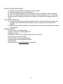
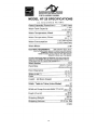
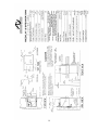
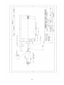
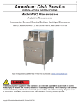
Effective Date: April, 15,2009
American Dish Service
MODEL HT-25
DISHWASHER
SERVICE MANUAL
900 Blake Street
Edwardsville, Kansas 66111
(913)-422-3700
IMPORTANT:
American Dish Service provides this information as a service to our customers. Keep all instructions for
future reference. Although ADS will make every effort to make sure the information in this service manual
is correct and up-to-date, ADS does not certify that this is the case, and should you decide to utilize this
manual, you do so at your own risk. ADS reserves the right to alter or update this information at any time
with out notice. Should you desire to make sure that you have the most up-to-date information, we would
direct you to the appropriate document on our web site: www.AmericanDish.com. The instructions
and guidelines in this owners manual are given with the assumption that the dishwasher
has been installed, operated, and maintained properly and in accordance with all applicable
Codes, Ordinances, and Safety requirements. Failure to install, operate, and maintain the
machine in this manner will void the ADS Warranty. ADS assumes no liability or control
over the installation, maintenance(service), or operation of the equipment. Product failure due to improper installation, maintenance, and operation is not covered under the ADS
Warranty.
WARNING:
During the operation of all dishmachines, chemicals, high voltage electricity, and normal operational functions can cause harm, bodily injury, or worse if proper installation, operation, and maintenance are not
observed. It is imperative that the operator(s) are trained in the operation and made aware of the hazards
that can exist. This is the responsibilty of the owner of this equipment. When installing, operating, or
maintaining your dishwasher you must follow all applicable safety requirements, including the wearing of
approved personal protective equipment.
2
TABLE OF CONTENTS
Description
Page
Installation, Tables
Plumbing
Electrical
Dispensers
Spray Arms
Operation
Motor Replacement
Hi Temp Design
Problem Evaluation
Preventive Maintenance
Warranty Statement
Cleaning Process
Water Control (“float”)
Specifications
Spec Diagram
Wire Diagram, 3 Phase
Timer Modification
Kit #388-1007
Wire Diagram, 1 Phase
Ladder Diagram, HT-25 (including all options of 2005)
Ladder Diagram, HT-25 (original 1995 wiring)
Ladder Diagram, HT-34/25 (including all options of 2005)
Layout, 3 Phase
Layout, 1 Phase
Wire Diagram, 3 Phase with Booster
Spray Arm Drawing
Bulletin #022-44
Motor Shaft Diagram
Replace Mercury Relay with Contactor
Booster Spec Sheet
Cam Timer Sequence Chart
3
5
5
6
7
7
9
11
12
12
13
15
16
17
18
19
20
21
22
23
24
25
26
27
28
29
30
31
32
33
34
35
NSF DATA PLATE
NSF Operational Requirements for
MODEL HT-25, Hot water sanitizing, single rack dishmachine
as manufactured by AMERICAN DISH SERVICE
Wash tank minimum temperature: 160° F
Final sanitizing rinse minimum temperature: 180° F
Final rinse minimum pressure: 20 psi
Wash cycle minimum time: 35 seconds
Final rinse minimum time: 10 seconds
MODEL HT-25, Chemical sanitizing, single rack dishmachine
Wash tank minimum temperature: 120° F
Final rinse minimum temperature: 120° F
Final rinse minimum pressure: 20 psi
Wash cycle time: 35 seconds
Final rinse minimum time: 10 seconds
Sanitizer required: 50 ppm available chlorine
To convert from hot water sanitizing to chemical sanitizing or the reverse,
adjustments shall be conducted by the manufacturer or its authorized service
agent.
Listing date 11/4/96
4
OPERATING INSTRUCTIONS FOR HT-25
INSTALLATION
First steps: Remove the packing material, including the cardboard shield for the tank heater.
Place the dishmachine in the desired position, then level the unit by adjusting the bullet feet in
each leg. The HT-25 can be used in either corner or inline arrangements. IMPORTANT. Do not
run this machine with the spray arm installed for the first two cycles following the installation. Rinse out any installation debris (such as grinding shavings or floor grout) that may damage bearings or rotating parts.
TABLE LAYOUT
Both corner table or inline arrangements can be attached to this machine model. For corner
layouts, the best arrangement will be with the table intersection meeting on the machine’s front
left-hand corner (your right hand side). This makes the scrap trap and control box more accessible. The only machine modification needed when changing between the two table layout styles
(inline/corner) is moving the tray track rail from the front position to the side position. This is done
by removing the two ¼” x 20 hex bolts and re-positioning the rail on the adjacent side. Note: If
you are installing this model in a corner configuration and the table backsplash is over 6”
in height, you may be required to modify the table backsplash by cutting a relief for the
door arm handle.
The tray track can be configured in corner or inline styles. The scrap box can be installed on the
right or left side. Note: For the corner setup the box must be on the left side of the machine and
the front panel (machine’s skirt) removed. The opening for the table lip is 21”. If the table lip is
wider than 21’ it must be cut to fit within the door guide opening. The “down turn” lip of the table
should not exceed ¾” in length. It is recommended that a distance of at least eight inches (8”) of
table surface between the scrap sink and the dishmachine.
PLUMBING
Incoming water supply is a single point ½” FPT, with a minimum of 20 PSI (at the final rinse
gauge), 180F final rinse, at 60 GPH recovery rate. Note: A booster heater is required for the
final rinse temperature of 180F. The installation point for incoming water is located on top of the
machine, approximately center and toward the rear. DO NOT supply a commercial dishmachine
with a 3/8” NPT incoming water line.
SERVICE NOTE: If you are having problems getting enough pressure during final rinse, the
problem will usually be found in the supply system. Think of the machine as a sprayer on the
end of a garden hose. If all of a sudden the water spray drops in pressure, or will not come out
with enough pressure, the problem will be found along the hose somewhere. Usually the line is
branched to other
fixtures, which causes a reduced flow to the machine. It is recommended that a
5
single line from the primary water heating system extend to the dishmachine or booster. The
pressure regulator on the machine is there to regulate pressure down to 20 psi, if the line pressure is too high. It cannot regulate the pressure up—that is a supply problem. Usually the problem is found in the booster heater, gate valve, inline regulators, or supply pipes.
LINE PRESSURE: Having too little or too much pressure in the final rinse sprays creates
result problems. With pressures much above 20 psi, the water begins to atomize and
rinsing is threatened. Too little pressure (below 20), spray arm rotation drops, coverage is
reduced, ‘make-up’ water volume is lessened, and soiled wash water stays on the ware.
Static line pressure means nothing to the process; running pressure (the pressure reading
during final rinse spraying) is the dynamic pressure or flow pressure. The dynamic pressure is what is required to be 20 psi.
[ This information is critical but is often overlooked ]
The drain on the HT-25 is made from two inch (2”) copper pipe, the manifold is attached by “nohub” plumbing connections to the tank and scrap box drains. The machine is normally shipped
with the scrap-box installed on the machine’s right-hand side. If the installation requires the
scrap-box installed on the machine’s left-hand side, the scrap box will require a different drain
manifold. This manifold can be order from ADS or soldered in place using “Tees,” “elbows,” “45
degrees,” and straight pipe. SERVICE NOTE: The drain manifold is attached with a plumbing
coupler called a “no-hub” which uses a 5/16” nut-driver tool to attach. Any commercial dishmachine of high capacity, should use 2” plumbing for drains; smaller drain lines are more liable to
clog. Reducers and 180-degree bends create severe clogging problems.
ELECTRICAL HOOK UP
The electrical hookup on a machine that has motors and heaters is important because of the
potential for injury and premature part failure due to faulty supply conductors or service voltage.
Undersized wire can cause early failure or intermittent operation. Loose connections can cause
burned wires and components over time. Operation of the machine without following manufacturer’s specifications will result in costly failures.
IMPORTANT >>>> This equipment requires a NEUTRAL wire
Three Phase Power Requirements:
(Single circuit) 208-230, 3 Phase, 40 amp, 60 Hz service
Wires: three 8 AWG copper wires for power, One 10 AWG wire for Neutral, and a ground
wire.
NOTE: 3 Phase has a rotational aspect, check for proper rotation, switch L1 and L2 to reverse
the rotation. (If the wash pump sounds loud and the sprays are very low, this indicates the rotation is backward.)
Single Phase Power Requirements:
(Dual circuits) 208-230, 1 Phase, 30/60 amp dual circuit, 60 Hz service
6
(1) Wires: two 10 AWG copper wires for power, One 10 AWG wire for Neutral, and a
ground wire.
(2) Wires: two 6 AWG copper wires for power
NOTE: 1 Phase has no rotational aspect.
SERVICE NOTE: 5/32 Allen wrench is needed for the main power distribution block. The
control box electrical conduit hole for the power supply wires is a “one inch conduit” hole.
The actual size of the hole is 1 3/8” located on the back wall, left hand side. Also, there is a
½” conduit hole, which is actually 7/8” in diameter, located on the bottom of the control box for
dispenser connections.
IT IS RECOMMENDED THAT NEW CIRCUIT BREAKERS BE INSTALLED FOR ANY
EQUIPMENT THAT CONTAINS ELECTRICAL HEATERS.
Wire size is important to electrical component life, undersized wire will result in premature
failure of contactors and motors.
We do not recommend using power from the HT-25 control box to supply power for controls
or devices such as exhaust fans.
WARNING: Always turn the power off for the machine before servicing the electrical system.
DISPENSING HOOK UP
The signal for dispensers is 120v and comes from the control circuit (unlike the ADC conveyor’s dispenser signal, which is 208v and comes from the power circuit). The dispenser hookup points are marked by a yellow sticker labeled “rinse” and “on” signals. The terminals are
located in the lower left-hand corner of the control box. There is an electrical conduit hole on
the bottom of the box for the dispenser wires. The control circuit supply power comes from
L1 and the Neutral line; it is protected by a 10 amp fuse and has the capacity of running the
dispenser’s power needs.
A female threaded (1/8” FPT) port is provided on the final rinse manifold. It is located at the
base of the manifold flange (mixing chamber) mounted to the hood and pointed toward the
rear. A 7/8” hole is provided at the back and center of the wash tank for a chemical inlet position. This is where you would install the bulkhead fitting for detergent feeding into the tank.
There is another 7/8” hole for a Chemical Probe located on the front wall of the lower tank,
near the machine’s centerline.
Do not mount the dispenser on top of the control box (reason: chemical leaking inside
electrical controls). Secure all chemical lines and attachment points. Make sure that chemical lines do not run over the top of electrical devices or inlet plumbing. (a leaking sanitizer
line can destroy the stainless cabinet and machine components)
SPRAY ARMS
The wash arms are interchangeable and rotate on bearings mounted horizontally in the top
of the wash arm hub. The four spray arm spokes are welded to the hub. Running a knife or
fork across the slot cleans the wash spray slots. Cleaning out the arms can be accomplished
by opening the captive end
7
cap and running water through the arm. The bearing can be disassembled for cleaning
with a screwdriver, should the need arise. It is not anticipated that disassembly would be
required; each time the machine goes into final rinse, a jet of water cleans out the bearing
shell. The wash base has a dome, which is held by the final rinse tube. This dome controls
the direction of water being pumped into the spray base. WARNING: Should metal installation materials become lodged between the dome and the hub, the wash arms will stop turning. Metal shavings, and especially sand can score these parts and cause rotation problems
for the wash arm. However, once these construction materials are gone, the hub and dome
interface will process food-related soils.
The final rinse arms are interchangeable and rotate on a bushing pivot. The pivot is
hollow and supplies the final rinse water to the rotating arm. There is a twist grip attached to
the top of the pivot by means of a snap ring. There are two washers made of polymer material, which serve as the rotational bushings for the rinse arm. After the wash arm is set in
place over the spray base dome, the final rinse pivot, holding the spray arm, can be screwed
into the final rinse tube which holds down the wash dome (There is a hole through the wash
arm bearing shells, the pivot goes through that hole and holds the wash arm in place along
with securing the final rinse pivot).
AFTER THE INSTALLATION CHECK-UP
1. Check rotation of the Wash motor—see arrow on pump housing. There is a 50% chance
that a 3 Phase motor will turn the right direction on installation. If you need to reverse
rotation, change the incoming L1 wire with the incoming L2 wire. Single phase machines
do not need this procedure.
2. Check for a high leg (delta system, 240v), if a high leg is present (200v) use L3 on the
power distribution block for that leg.
3. Check the heater circuit breaker located in the control box; make certain it is in the “on”
position. The toggle should be up.
4. Check the water level control mechanism located at the machine’s right rear top of cabinet. Take the cover off the box and inspect the movement of the lever and rod. They
should be free moving and without restriction. When the machine is turned on, the water
control will fill automatically to the upper limit of the control. It is normal for the water level
to be below the scrap trays after initial fill. Several cycles later the machine will begin
to overflow into the scrap trap mounted on the side. SERVICE NOTE: to test the water
control system, turn the machine on and let it fill completely. Then move the lever in the
water level box up with your finger, it should begin to fill but shut off as soon as you take
your finger away. Do this rapidly 10 or 20 times, it should never stick on or continue to fill.
If it does, the problem will be caused
by something rubbing on the rod, lever, or weight. In rare cases, the water level switch
may have lost the required tension on its return button, and must be replaced. These
switches are specifically designed with a certain tension on the button (marked with a 5);
other switches will not work in this system.
Check the machine’s operation by placing a rack inside, close the door and push the start
button located on either side of the control box. The indicator
8
1. lamps will show the wash and rinse cycle duration, when the rinse lamp turns off, the cycle
is over. The door may now be opened and the rack removed. During the rinse cycle,
check the pressure gauge at the final rinse manifold. It should read 20 psi. It can be adjusted to a lower pressure by turning the regulator screw counter-clock wise (CCW)—Remember, up = is down.
2. Check all end caps in the wash and rinse arms. Make sure all the screens and pump filter
are in place. Make sure the cardboard packing material is removed from around the tank
heater.
THE RULE FOR ALL DISHMACHINES: The Installation is KEY to reduced service problems and complaints.
Important Note:
Before running the machine for the first time, wash out the inside by operating without the
spray arms. This will help remove the installation debris and metal filings that cause the spray
arms to bind. If they lock up during the first cycle, remove the four arms, then clean the spray
base and wash arm hubs. Rinse out the machine by running a cycle without the arms, then
dump the tank and refill.
Food soil will not cause this problem. However, installation grit, metallic or PVC shavings will
stop the arms from turning. They are forced into the hub and bearing clearances when the
pump first starts up. These fragments cause rotation stoppages. This problem will cease
after the machine is cleaned and normal operations begin.
MACHINE OPERATION
After the machine is operational and the tables are cleared, remove all packing material (heater supports) then wash out the tank, give attention to any installation debris left over. DO NOT
PUT THE SPRAY ARMS IN UNTIL THE MACHINE HAS RUN SEVERAL CYCLES. Now, fill
the machine by turning on the master switch. The HT-25 will automatically fill with water to an
operational level. After the pump motor starts, the machine will fill once more to compensate
for the water used by the pump. This is normal operation. Now, place the wash arm on the
spray base dome, the wash arms are interchangeable up and down. Now screw in the final
rinse spray arm by turning the twist grip pivot into the spray base center tube. It is easier to
hold the upper wash arm in place while turning the final rinse arm and securing the entire upper assembly.
Place a rack in the machine and close the doors, push the start button. As the machine runs
through the cycle (Both 60 seconds or 45 seconds are available),
you will hear the sound of the wash sprays, however, when the final rinse begins, the noise
level drops dramatically. Some people have thought it was finished, but observe the cycle
light to see when the final rinse is completed. Then open the doors and remove the rack.
WHAT TURNS THE MACHINE ON AND OFF
There is a timer that causes the machine to run. The cycle is started when the start button is
pressed and the instant start relay is energized, which energizes
9
the cam timer. Everything is keyed off the master cam. The first cam is the master and it begins
the cycle by sending power to the timer motor. The second cam immediately turns on the contactor for the wash motor. The third cam will turn on the final rinse solenoid. The fourth cam switch
is a spare.
The heater is controlled by the thermostat and the level control switch (float). If there is no
water present in the tank when the machine is turned on, the level control switch will turn off the
heater and open the fill solenoid. When the tank is full, the switch will shut off the water and then
turn on the heater. If the incoming water is hotter than the settings on the thermostat, the thermostat will shut the heater down until the water temperature drops below the set point. NOTE: To
increase the temperature set point, turn the thermostat center-rod counter clock-wise (turn to the
left). The red light above the Mercury Relay in the control box will show (on) when the thermostat
is sending power or when it is satisfied (off) in the temperature of the tank.
A test to see if the machine’s tray track and tables are set up right is to place a rack on the soil
table then push it through the machine and on to the clean table. It should slide easily across all
points.
CAUTION:
Always disconnect power to the machine before servicing.
Heaters will remain hot immediately after emptying of machine.
Turn machine off before opening for inspection.
MOTORS
It is recommended that the pump motor be replaced as a unit. This is classified by ADS as
“pump motor complete, less cover.” The reasoning is: High Temps are generally placed in high
volume accounts, which have little space or time for major repairs. The simplest procedure for a
fast replacement is to remove the four housing bolts, disconnected the electrical connection and
replace with a new unit. This can be accomplished without extensive service knowledge or down
time for the restaurant. If there is a problem with the seal, shaft, or impeller the resulting time
investment could cause an extended disruption.
This is best managed by preparation rather then reaction. The primary events include heater/circuit breaker, wash pump/contactor, and damaged or broken parts. Any of these events can be
replaced and operations returned to normal within 20 minutes if the assembles are readily available. ADS has kits or lists of these major items and they can be purchased in assembled form.
Once a replacement is speedily made, the faulty part can be returned to the shop. At the shop
there is enough time and resources to perform an adequate repair; the repaired part then becomes the replacement assembly for the next event. This is the most efficient way to service the
high volume business. Expecting even qualified service persons to repair system assemblies
can be a risk. It can lead to multiple-day events. All possible or needed resources are simply not
available at the restaurant.
10
3HP MOTOR REPLACEMENT
SEAL REPLACEMENT PROCEDURE
1 TURN OFF POWER TO THE MACHINE. Empty water from the wash tank and open petcock on wash pump motor.
2 Remove the two mounting bolts that secure motor to frame.
Take out the (4) four 3/8” bolts that hold rear pump housing to the front pump cover.
3 Slide motor and rear pump housing out of the pump cover. Place the unit on
the floor
and open the rear access plate on the motor.
4 Disconnect the (3) three lead wires that are attached to terminals L1, L2, and L3. Remove
the conduit from the motor.
5 Remove the impeller by taking out the secure bolt and. The impeller slides off the keyway.
If it does not slide off easily, gently tap it from behind. Heavy blows from a hammer will damage the impeller and shaft alignment.
6 Remove the (4) four 3/8” x7/8” bolts that hold the rear pump housing to the motor. Carefully
slide the housing off the motor; pay particular attention to the shaft seal. The graphite section
(black face) is the part that slides on the motor shaft. The ceramic section (white race) is the
part that seats in the rubber boot in the housing. Slide the graphite section off. Be careful not
to crack the ceramic when the pump housing is removed from the motor.
Important Note: The 3hp motor shaft extension with the pinned and set screws
adapter is not field repairable or serviced. It is installed at the factory and must be replaced
as an integral part of this motor. However, the 1999 7/8” motor shaft, has only a 1.5” diameter collar that slides over the motorshaft. It is sealed with internal O rings and held in place
by the impeller. This motor is simpler and can be setup in the field without special tools.
7 To assemble, reverse the order above. If you are replacing the seal make sure the rubber
boot on the ceramic is fully seated at the bottom of the pump
housing. Make sure the shaft is clean. Put the boot and ceramic section together first, then
press it into the housing first. It will be helpful to use some hand soap or dishsoap (Dial) to
slide the boot with white ceramic section into the pump housing. The smooth surface will
face out toward you; the grooved side will face the housing. Do not put grease or oil on
the seal. Inspect the graphite section; make sure there are no cracks or chips on the face of
the black graphite. Slide this section onto the motor shaft and install the spring and finally the
retainer shield. Place the impeller on next. The keyway and slot should be free from damage
or distortion. If the keyway is enlarged, the motor will need replacement. If the impeller is
also has a damage key slot, it must be replaced.
8 When the pump assembly is placed back into the pump cover, properly seat the o-ring gasket and use some lubricant to avoid pinching the o-ring. To
11
determine whether the O ring is good or not, roll it between your fingers. You should not feel a flat
spot.
HI TEMP DESIGN
The term “Hi Temp” refers to the sanitation process of the dishmachine. Or, in other words, the
type of process used to achieve an acceptable kill rate in bacteria. There are typically two methods, chemical or thermal sanitizing. In high temperature (thermal kill) sanitizing, the surface of the
dishware must reach a temperature of 165F for a minimum of ten seconds. This is accomplished
by spraying 180F water over the dishware during the final rinse. This elevated temperature meets
the Heat Unit Equivalent (H.U.E.) tests required for NSF certification.
The HT-25 supports both methods of sanitizing, NSF lists the HT-25 as a dual sanitizer. This
means the machine’s design can serve in both roles. The final rinse system delivers high temperature sanitizing or chemical sanitizing sprays with the same water consumption rates. The choice
of the boosted incoming hot water (min. 180F) or chemical dispenser application (min. 50 ppm
chlorine) is a result of the equipment added to the machine (booster or 3 product dispenser). The
best application of the HT-25 is the High Temp sanitizing.
HT-25 Commercial Dishmachine
QUESTIONS TO EVALUATE OPERATION OF MACHINE
1. Will the machine fill with water when it is turned on for the first time during a new work period?
If it does not, is the “ON” light illuminated when the master switch is turned on? If not, the machine will need electrical service. [Service issue]
2. When the machine fills with water, what is the incoming water temperature? It should be 158F
for Hot Water Sanitizing and 120F for Chemical Sanitizing. This requirement is supplied by
the building’s primary water heating source. [Building maintenance issue]
3. After the machine has filled with water, a rack of dishes can be pushed into the machine on
the “soil table” side, and the door closed. Push the start button, the wash pump should begin
operation. If it does not, look at the inspection door, is it fully closed? [Operator issue]
Does the machine continually fill, causing the primary water-heating source to run out of hot water? This condition will be a result of water escaping from the
12
1. tank. From the wash tank, the likely cause will be water not coming in from the final rinse or
leaking out of the drain. [Install and service issue]
2. Is the final rinse water at the correct temperature? 180F min. for Hot Water and 120F min. for
Chemical. The correct final rinse temperature is critical to operational temperature. [Building
maintenance issue]
3. If a surging sound is coming from the wash pump, check the pump filter and tank trays. They
may be filled with soil. Clean the filter and trays, refill the machine. [Operator issue]
4. Check for free rotation of the spray arms. Both wash and final rinse arms should turn freely.
Upper and lower arms are interchangeable. If an arm is not turning freely, remove the arm
and look for debris that may be lodged in the bearing area or against the hub (rotating part)
and dome (stationary part of base). [Operator issue]
5. Chemical supply is provided by the chemical company. [Service issue]
6. Glass appearance is often referred to as “results.” If the results are poor, there are several
factors, which effect the outcome of the washing process. Rinsing is the most challenging
aspect for any dishmachine. The following are three areas of problem sources.
First is procedure. If the dishes are not placed so the sprays can reach the surface, the
results will be poor. If large amounts of soil are left on the dishware, this may slow the
washing process.
Second is temperature and water condition. If the water has lower temperature and scale
producing elements, results will suffer. The machine cannot overcome these problems.
They must be treated before being used in the dishmachine. This is a building issue.
Third, installation problems are the # 1 cause of service disruptions. If the machine is improperly installed no amount of tuning or adjustment can compensate for the lack of essential elements. The installer must return and correct the omitted elements of the installation.
HT-25
Preventive Maintenance Schedule
Three General areas must be inspected
1) Spray Arm Rotation
2) Water control mechanism
3) Final Rinse Pressure
SPRAY ARM ROTATION
1) Run a cycle, lift the door quickly to see if both upper and lower wash arms are turning
(about 60 RPM), you will get wet doing this.
2) When final rinse turns on, do the same procedure by lifting the doors quickly and observe both upper and lower final rinse arms (about 60 RPM)
3) Check that end caps are in place and spray slots and tips are clear. Turn arms, all
should turn freely.
13
WATER CONTROL MECHANISM
1) Check for free movement of suspended rod and weight
2) Suspended weight is free moving and clear
3) Lever is free moving and has 1/16” clearance from box or attaching locknut. Operate
the lever 10 or 20 times with the tank full of water, it should not stick on “fill.” If it does stick,
the problem will be interference with the rod, weight, or the switch button spring may be too
weak.
FINAL RINSE PRESSURE
1) Pressure at the final rinse manifold should be 20 PSI. Below 20 will reduce rotation and
coverage, about 20 will make it more difficult to inject chemicals in the stream of the
manifold.
2) Adjusting the pressure regulator on the machine will not make up for low pressure coming
to the machine.
NORMAL CHECKS
1) Check for bent or damaged parts
2) Screens and trays are all in good order
3) Drains are clear
4) Dispenser is functional and adjusted w/no leaks of chemical
5) Curtains are in place and clean
6) Correct leaks to avoid damaged motor
7) Spray patterns are consistent and typical
8) Check racks
9) Lime build-up on any dishmachine is a problem
14
AMERICAN DISH SERVICE
Limited Warranty
Parts and Labor
American Dish Service warrants to the original purchaser that its products are free of defects in material and workmanship and
agrees to repair or replace, at its option, any parts that prove to be defective within ninety (90) days from date of purchase.
American Dish Service may require reasonable proof of your date of purchase. Therefore, you should retain your copy of the
invoice or shipping document.
In addition, American Dish Service will exchange any part covered under this limited warranty which is found defective, as
determined by American Dish Service, under normal use and service up to two hundred and seventy (270) days following the first
ninety (90) day limited warranty period as described above, excluding feed line, flexible hose, and squeeze tubes.
The warranty does not cover equipment subject to accidents, freight damage, improper power and/or plumbing hookups, or lack
of routine required maintenance as determined by American Dish Service. This warranty is void if the defect is due to improper
installation, high chemical concentrations, misuse, modification of the machine, repair or servicing other than by an authorized
American Dish Service dealer, or authorized agent, or operated in a manner contrary to applicable factory instructions herein or
failure to perform all required maintenance.
The timer cams for water and chemicals are adjustable. Proper adjustment is the responsibility of the installer of the equipment.
This warranty does not extend to machine malfunction resulting from improper cam adjustment.
All warranty work for machines will be performed, within the ninety (90) day period, during normal working hours, by an authorized
agent receiving prior authorization by American Dish Service. Overtime charges and expediting charges such as “overnight” and
“air freight” will be the responsibility of those requesting service outside normal American Dish Service procedures. Expenses due
to disconnections, delivering, returning, and reinstalling the machine are borne by the purchaser and are not the responsibility of
American Dish Service. Travel charges for time and mileage outside normal service area (75miles) shall be the responsibility of
those requesting service.
Defective parts become the property of American Dish Service. Parts replaced within the warranty period carry warranty only
until the end of the original limited warranty. Replacement parts not supplied by American Dish Service will relieve American Dish
Service of all future liability and responsibility. American Dish Service will provide the names of the nearest authorized dealers
upon request.
ADS is not responsible nor liable for any conditions of erosion or corrosion caused by corrosive detergents, acids, lye or other
chemicals used in the washing or cleaning process.
This warranty is void outside of the United States of America.
AMERICAN DISH SERVICE HAS MADE NO WARRANTIES THAT THE GOODS SOLD OR SERVICES PROVIDED ARE
MERCHANTABLE OR FIT FOR ANY PARTICULAR PURPOSE AND THERE ARE NO WARRANTIES, EXPRESS OR
IMPLIED WHICH EXTEND BEYOND THE EXPRESS LIMITED WARRANTY CONTAINED IN THIS AGREEMENT. UNDER NO
CIRCUMSTANCES SHALL AMERICAN DISH SERVICE BE LIABLE FOR ANY LOST SALES, LOST PROFITS OR ANY OTHER
INTANGIBLE LOSS OR ANY OTHER SPECIAL OR CONSEQUENTIAL DAMAGES ARISING OUT OF THE USE OR ANY
INABILITY TO USE THE PRODUCTS SOLD BY AMERICAN DISH SERVICE.
American Dish Service’s liability under this agreement shall in no event exceed the amount paid for the equipment purchased from
American Dish Service. This warranty will be void if the Warranty Registration Card is not returned to American Dish Service within
30 days of the equipments installation.
This warranty is void if the equipment is installed for residentuial use.
Any action under the terms of this Warranty must be commenced within one year from the date of purchase of the equipment.
15
16
WATER CONTROL MECH.
1. Free moving flipper and rod
2. 1/16” clearance on holddown nut (flipper)
3. Wires are clear of mech.
4. Rod has no interference with tube or box
5. Armor tube is seated in the upper socket
6. Bracket has equal clearance on both sides
7. Bracket is secure in upper position
8. Weight is 238 grams
9. Switch is tested: 5oz-min 6oz-max
10. Wash rod is 35.187” long (o/a)
11. Rinse rod is 29.25” long (o/a)
17
18
19
20
21
22
23
24
25
26
27
28
29
30
31
32
33
Booster Heater Specifications
Model
KW
40F Rise 70F Rise Ship. Wt. ADS Stock Amp/208/3ph Amp/208/1ph Amp/240/3ph Amp/240/1ph
C-6
C-12
C-15
C-24
C-27
6 kW
12 kW
15 kW
24 kW
27 kW
60 gph
120 gph
151 gph
241 gph
271 gph
34 gph
69 gph
86 gph
138 gph
155 gph
118 lbs.
120 lbs.
120 lbs.
142 lbs.
142 lbs.
stock
stock
stock
stock
stock
40a, 8AWG
50a, 8AWG
60a, 6AWG
100a, 3AWG
100a, 3AWG
40a, 8AWG
90a, 3AWG
90a, 3AWG
150a, 1/0
175a, 2/0
30a,
40a,
50a,
90a,
90a,
10AWG
8AWG
3AWG
3AWG
3AWG
ADS built
40a, 8AWG
Not available
40a, 8AWG
40a, 8AWG
70a, 4AWG
90a, 3AWG
125a, 1AWG
150a, 1/0
C4 - C18 21" long 21" tall
13" wide
C24 & up 24" long 18" tall
18" wide
All tanks 6 Gallons
Volt avail. 208v,I & III 240v,I & III 480v, III
B-13
2 gal tank
13.5
80
40
34
Not available
35
NOTES:
36
American Dish Service
Manufacturer of low and high temperature
Commercial Dishwashers and Glasswashers
900 Blake Street
Edwardsville, Kansas 66111
Ph:(913) 422-3700
Fax:(913) 422-6630