1
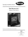
Operating & Installation Manual
The Becton MK 3
Range of Gas Stoves
(Becton 7 MK 3 Gas Stove)
PLEASE RETAIN THESE INSTRUCTIONS FOR FUTURE REFERENCE
FOR USE IN COUNTRIES
GB & IE
Rev 11
Part No. AFS1125
Congratulations on your choice of a Becton Gas stove .
More than 20 years experience has been put into the development of
our Becton Family to ensure ultimate performance and years of
trouble free enjoyment.
Every detail on the fire has been carefully engineered and designed
which is why we are so confident in the reliability of our product
that we offer a Lifetime Guarantee.
Should you have any questions about our Becton Stoves that are
not covered in this manual, please contact the Aarrow dealer in
your area, or call our Technical support department on
01308 427234
Flaming Good Fires!
© COPYRIGHT March 2004
Arada Ltd
This booklet has copyright & may not be
copied in whole or part or used for any
purpose other than that for which it is
supplied without express written consent
from Arada Ltd.
Becton Bunny & Becton 7 mk3 Gas stoves
CONTENTS
Page
INTRODUCTION
Page
SERVICING
Safety Notices
4
Details of Pilot Assembly
18
General Information
4
Door Trim
19
Statutory Requirements
5
Fire Door Glass & Seal
19
Burner Assembly
20
Regular Service
20
Annual Service
21
Cleaning Outer Services
21
Cleaning Door Glass
21
Fault Diagnosis
22
OPERATING INSTRUCTIONS
Technical Data
6
Fire Dimensions
6
Fitting the Lining Panels
7
Arranging the Coals
8
Lighting & Controlling The Fire
9-10
SPARE PARTS
INSTALLATION
General Components
23
23
Installing The Fire
11
Accessories and Options
Fitting The Feet
11
Notes
24-25
Spare Parts List
26-28
Flue System
11-13
Fire Location
13
Combustible Shelf Clearances
14
Hearth Requirements
15
Connecting The Gas Supply
15
Pressure Test Sequence
15
Fire Testing
16
Installation Check List
17
Becton Bunny & Becton 7 mk3 Gas stoves
GUARANTEE
Lifetime Guarantee
Customer Registration
29 & 31
29
SERVICE RECORD
Service Record
30
Lifetime Guarantee
31
Final Factory Checklist
32
3
INTRODUCTION
References in this manual to British Standards and
Statutory Regulations and Requirements apply only
to the United Kingdom. For Ireland the rules in
force must be used.
Before installation, check that the local distribution
conditions, nature of the gas, pressure and the
adjustment of the appliance are compatible.
The manual is an important part of the appliance
and must by law be handed to the end user on
completion of the installation.
normal hygiene rules are followed.
Always wash your hands before eating or
drinking.
• In the event of a gas emergency, consult the
telephone directory and ask for your local
gas supplier.
_________________________________________
GENERAL INFORMATION
SAFETY NOTICES
• Do not attempt to burn rubbish or any other
material in this appliance.
• This fire must only be operated with the fire
door shut and secured.
• Do not use the appliance if the glass is cracked or
broken.
• Do not make any unauthorised
modifications to the appliance.
• It is recommended that the fire be guarded
to protect the young and infirm using a
fireguard complying with BS8423:2002.
• Coal set -The coal set contains Refractory
Ceramic Fibres (R.C.F), which are man
made vitreous silicate fibres. Excessive
exposure to these materials may cause
temporary irritation to the eyes, skin and
respiratory tract. Care must be taken when
handling these items to ensure the release of
dust particles is kept to a minimum. To
ensure that the release of fibre from these
items is kept to a minimum, during
installation and servicing it is recommended
that a vacuum cleaner fitted with H.E.P.A.
filters is used to remove any dust, soot or
any other debris accumulated in and around
the appliance. This should be performed
before and after the installation. It is
recommended that any replacement item(s)
are not broken up but sealed within a heavy
duty polythene bag and clearly labelled
"R.C.F. waste". This is not classified as
"hazardous waste" and may be disposed of
at a tipping site licensed for the disposal of
industrial waste. Protective clothing is not
required when handling these items but it is
recommended that gloves are worn and
4
All materials, appliances and equipment used
should be fit for their purpose, be of suitable
quality and workmanship and should comply with
the applicable British Standards.
Before continuing any further with the installation
of this appliance please read the following guide to
manual handling.
• Always obtain assistance when lifting the
appliance.
• When lifting always keep your back
straight. Bend your legs not your back.
• Avoid twisting at the waist. It is better to
reposition your feet.
• Avoid upper body/top heavy bending. Do not
lean forwards or sideways when
handling the fire.
• Always grip with the palms of your hands.
Do not use fingertips for support.
• Always keep the stove as close to the body as
possible. This will minimise the cantilever
action.
• Use gloves to provide additional grip.
Becton Bunny & Becton 7 mk3 Gas stoves
INTRODUCTION
IMPORTANT NOTICES
A qualified gas engineer must carry out the
installation and servicing of this appliance in
accordance with these instructions and in
compliance with current Building Regulations.
Such person must be a registered CORGI
engineer.
This appliance is designed to run on natural gas
only. Warning - Only use the appliance with the
specified gas.
The fire is fitted with a safety device to shut down
the appliance if there is inadequate flue draw. If the
fire shuts down for no apparent reason check
chimney and air inlets to the room. In all cases the
fire must not be re-lit until the safety aspects have
been checked by a qualified gas engineer.
Please note the following;
• The safety device must never be put out of
action.
• Sealed components must not be interfered
with.
• Servicing instructions and part identification
numbers are given towards the back of the
manual.
• Only use genuine Aarrow parts for
replacements.
• Ventilation, purpose built ventilation is not
normally required for either appliance,
normal adventitious room ventilation being
sufficient.
• Coal Set, see safety notice on page 4.
All surfaces except the control knob, the control
door handle and control door are considered to be
working surfaces.
Warning: THIS GAS APPLIANCE MUST BE
SERVICED EVERY TWELVE MONTHS BY A
QUALIFIED GAS ENGINEER.
STATUTORY REQUIREMENTS
The current Gas Safety (Installation and Use)
Regulations (as amended).
The Building Regulations for England and Wales
2000 ref Approved Document J 2002 edition
(issued by the DTLR).
The Building Standards (Scotland) (Consolidation)
Regulations.
Detailed recommendations are outlined in the
current issue of the following British Standards:BS5440 parts 1 and 2, BS5871 part 1 and BS6891.
Any Manufacturer's Instructions must not be
taken as overriding statutory requirements.
_________________________________________
CERTIFICATION
This appliance is CE certificated for performance
and safety. Therefore, it is important that no
alteration is made to the appliance.
Any alteration not approved by Arada Ltd. will
invalidate the guarantee.
Warning: Under no circumstances must the fire
be operated if the glass is cracked or broken.
Warning: If
operational
appliance, it
investigated
engineer.
it is known or suspected that an
or ignition fault exists on the
must not be used until it has been
and corrected by a qualified gas
Becton Bunny & Becton 7 mk3 Gas stoves
5
OPERATING INSTRUCTIONS
FIRE DIMENSIONS
TECHNICAL DATA
Category I2H For use in GB and IE at a
supply pressure of 20mbar
Becton
Bunny
Natural Gas
Becton 7
Natural
Gas
Main Burner
Aeromatic
AC13/112511
(mod 334)
Aeromatic
AC13/112511
(mod 334)
Injector
Bray 82-700
Bray 82-700
Max. Heat
Setting
Heat Input
(net)
3.7 kW
5.0 kW
Fig. 2
Gas Rate
Cold Setting
Pressure
0.391m3/hour
0.529m3/hour
1.5mb
3.5mb
2.4 kW
3.3 kW
Min. Heat
Setting
Heat Input
(net)
Gas Rate
NOx CLASS
6
0.254 m3/hour
0.349 m3/hour
CLASS 4
CLASS 4
Becton Bunny & Becton 7 mk3 Gas stoves
OPERATING INSTRUCTIONS
FITTING THE LINING PANELS
Becton 7 only. The lining panels supplied are to be
installed into the fire before the coal matrix is
fitted. Note: The lining panels are reversible (brick
or plain pattern)
3. Then rotate the rear edge until the top faces
match up the angle faces at the rear of the fire.
(See Fig. 3c) Repeat exercise for the left hand side.
Ensure the appliance is cold.
With the fire door open, the glass retaining frame
and the coal set removed, proceed as follows:
Do not force the linnings into position.
1. Position the rear lining face down at the rear of
the fire. Ensure the cutout faces the rear of the fire.
Fig. 3c Fitting the side linings
4. Rotate the rear lining to bring it vertical (Fig. 3d)
Fig. 3a Positioning the rear lining
2. Locate side lining in the right hand side of the
fire. First position the tall edge into the radius at the
front of the fire.(See Fig.3b below)
Fig. 3b Fitting the R/H side lining
Fig. 3d Rotating the rear lining
5. Centre the assembly. Line up each end of the rear
lining with the edges of the fixed matrix plate. (See
Fig. 3e)
Fig. 3e Liner panels assembled in the fire.
Once the lining panels are fitted, arrange the coals.
See “Arranging the coals” on page 8.
Becton Bunny & Becton 7 mk3 Gas stoves
7
OPERATING INSTRUCTIONS
ARRANGING THE COALS
Safety Notice - Please see SAFETY NOTICES
ref. Coal set page 4.
Warning: The coals and the coal matrices are
fragile ensure they are handled carefully.
Ensure location is correct. Do not force the
matrix into position. If the coals and/or the coal
matrices are damaged they must be replaced
with genuine Aarrow replacement sets.
Warning: An incorrect coal layout may cause
soot to build up inside the fire and therefore
invalidate the guarantee.
Ensure the appliance is cold.
Step 1 Place the base matrix on the matrix plate
centrally between the end tabs of the location bar.
(Fig 4a)
Step 3 Becton 7 only. Locate 2 off end coals each
side of the base matrix. (See underside of coals for
hand identification) (Fig 4c).
Fig 4c
Fig 4a
Step 2 Place the rear matrix cut out section over
the base matrix and centralise the assembly
between the end tabs of the location bar. Ensure the
rear matrix is pushed back against the location bar.
(Fig 4b)
Fig 4b
8
Becton Bunny & Becton 7 mk3 Gas stoves
OPERATING INSTRUCTIONS
LIGHTING
THE FIRE
&
CONTROLLING
Under no circumstance must the fire be operated if
the glass is cracked or broken.
Step 1c. Keep the control knob pressed in for a
further 15 seconds and then release. The pilot will
remain alight.
If pilot does not remain alight repeat this procedure.
Open the gas control access door situated at the
bottom of the appliance. Always use the control
door HANDLE.
Please note that when purging the gas supply it is
usual to have to keep the control knob depressed in
the spark position for longer periods of time.
Step 1a. To ignite the pilot push the control knob in,
turn anti-clockwise towards the spark position and
hold in for 15 seconds. (Fig 5a)
The pilot can be viewed through the L/H & centre
front slots in the base matrix.
Step 2. To ignite the main burner, rotate the control
knob anti-clockwise to the HIGH position (fig 5c)
Fig 5c
Fig 5a
Step 1b. Keep the control knob pressed in and turn
For maximum heat output leave the control knob at
the high position
For minimum heat output, rotate the control knob
clockwise to the LOW position. (Fig 5d)
anti-clockwise to the pilot position. (Fig 5b)
Fig 5b
Becton Bunny & Becton 7 mk3 Gas stoves
9
OPERATING INSTRUCTIONS
Step 4. To extinguish the pilot, turn the control knob
to the OFF position. (Fig 5f)
Incorporated into the pilot assembly is a flame
failure device designed to shut off the gas supply in
the event of the pilot flame being extinguished
while the fire is unattended.
Should the pilot flame blow out accidentally or
intentionally whilst the fire is running, no attempt
should be made to re-light the gas for at least
three minutes.
Fig 5d
To restart the fire turn the control knob to the off
position and repeat the lighting & controlling the
fire instructions.
The flame failure device is a safety feature required
by law and must not be put out of action by the
installer. If this device or any of its parts are to be
replaced, only original manufacturer's parts are to
be used.
Repeated operation of the flame failure device
indicates that there maybe a problem with the flue
draw. In this situation no more attempts at
operating the appliance should take place and your
qualified gas engineer should be contacted to
investigate and rectify the problem.
Fig 5e
Step 3. To turn the main burner off while keeping
the pilot alight, rotate the operating knob back to
the PILOT position. (Fig 5e)
Fig 5f
10
Becton Bunny & Becton 7 mk3 Gas stoves
INSTALLATION
INSTALLING THE FIRE
Your CORGI qualified gas engineer should install
the fire in accordance with the following
regulations and standards:The Gas Safety (Installation and Use) Regulations
1998 (as amended).
The Building Regulations for England and Wales
2000 ref; Approved Document J 2002 edition
(issued by the DTLR).
The Building Standards (Scotland) (Consolidation)
Regulations.
BS5440 parts 1 and 2 1990, BS5871 And these
Installation Instructions.
Warning: Failure to comply with the
regulations, requirements, or these instructions
will invalidate the guarantee and could have
hazardous consequences.
Please note that in tight recesses the gas supply
point may be inaccessible. Therefore it may be
necessary to connect the pipe for the gas supply to
the fire before installing the fire into its recess.
FITTING THE FEET
Care should be taken when fitting the feet not to
damage the painted surfaces of the fire.
• The feet (4 off) are positioned in each corner of
the fire base using the washers and screws
provided.
• Tools required: A no. 2 pozidrive screwdriver.
FLUE SYSTEM
The stove must be connected to a suitable and
efficient flue that provides a good updraught to
safely take the products of combustion (fumes)
from the stove outlet to the outside air. To ensure a
good updraught it is important that the flue gases
are kept warm and that the flue size suits the stove.
The termination of the outlet at the top of the flue
also needs to comply with the Building
Regulations. The minimum effective height of the
Becton Bunny & Becton 7 mk3 Gas stoves
chimney must be at least 3 metres and when warm
the flue draught should be between 0.05 and 6mb
(0.5mm to 6mm water gauge).
The Bunny requires a minimum flue size of 100mm
(4 inches) and the Becton 7 requires a minimum
flue size of 125mm (5 inches). If the stove is being
connected to a chimney with an internal flue size
greater than 225mm (9 inches) diameter or 200 x
200mm square, a 125mm (5 inches) diameter
stainless steel flexible flue liner complying with BS
715 should be installed in the flue.
If a new chimney is being provided it should fully
comply with the relevant Building Regulation
Requirements and BS 5440: Part 1. Suitable types
of chimney include the following.
• Masonry chimney built with clay or concrete liners, or a chimney block system meeting Building
Regulations.
• Precast concrete gas flue block complying with
BS 1289: Part 1
Factory made metal chimney complying with BS
715 (often called "Twin wall Class 2 chimney") or
Factory made metal insulated chimney complying with BS 4543: Part 2 (often called "Class 1 prefabricated metal chimney"). To ensure the flue
gases are kept warm an insulated chimney system
should be used if the chimney is positioned outside
the building.
The flue must be terminated with a suitable
chimney pot or cowl and the chimney or flue shall
be swept prior to installation unless the chimney is
clean and unobstructed.
The flue and chimney installation must be
carefully checked by a competent person before
fitting the stove to ensure it is suitable and will
work safely. The flue must also pass a Flue flow
test (smoke test) to BS 5440: Part 1.
For advice on flues and chimneys contact;
NACE (National Association of Chimney
Engineer): telephone 0800 0924019
www.nace.org.uk
or
NACS (National Association of Chimney
Sweeps): telephone 01785 811732
11
INSTALLATION
The Becton gas stove is designed so that the flue
can be fitted to either the top or the rear of the
appliance.
Provide a minimum vertical height of 600mm of
flue from the height of the rear flue outlet. See
figure 7b.
Fit the flue spigot and blanking plate for either top
or rear flue outlet in accordance with figure 6a or
6b (below).
Closure Plate
#Connect the flue spigot to the rear outlet.
#Connect a flue extension to the spigot.
#Fit the closure plate in fireplace.
#Position the fire so the flue extension passes
through the hole in the closure plate.
#Ensure all joints are suitably sealed.
See Figure 7c.
TOP FLUE
Provide a minimum vertical height of 600mm of
flue measured from the top of the appliance.
See Figure 7d.
Lock the blanking plate in place by rotating anticlockwise and tighten by tapping gently with a
block of wood and mallet. Fit the spigot to the
unused opening in the same way. The units are
sealed by the attached gaskets.
Move the fire, with flue spigot in place, into
position under the flue and seal the spigot/flue
connection with fire cement. (Ref. Fig. 6c).
It is recommended that a smoke test is performed
inside the fire to ensure that adequate flue draw is
evident.
Fig 6c
REAR FLUE
Fig 7a
Open Hearth
Fit and seal a ‘T’ section (with soot box) directly
into the flue spigot. The maximum horizontal
section allowed is 150mm.
12
Becton Bunny & Becton 7 mk3 Gas stoves
INSTALLATION
non- combustible closure plate,
incorporating access for cleaning debris.
non- combustible closure plate,
incorporating access for cleaning debris.
Fig. 7d.
Fig. 7b.
FIRE LOCATION
The appliance must not be installed in a room or
space, which contains a bath or shower.
This fire is designed for use with either top or rear
flue outlets and must be mounted on a hearth with
a minimum of 12mm non-combustible material
thickness.
There must be a minimum of 200mm clearance
from the sides of the fire to any combustible
sidewalls. Fig7a.
For clearance from the top of the fire to any
combustible shelf. Fig 7b. (See Graph 1).
There must be a minimum of 230mm from the
rear of the fire to any combustible back wall.
Fig 7b.
Fig. 7c
With a Non-combustible back wall the fire can be
pushed back until the top diverter touches the wall,
although to improve access and air circulation a
minimum distance of 100 mm is recommended.
Fig 7c.
Reference non-combustible side walls a minimum
of 100mm is recommended.
Do not place any furniture or furnishings (including
curtains) within 1 metre of the fire.
Becton Bunny & Becton 7 mk3 Gas stoves
13
INSTALLATION
The minimum height from the extreme top surface of the fire to the underside of a shelf or other projection
made of wood or any other combustible material is shown on graph 1.
Graph 1.Combustible Shelf Clearances
The recommended minimum height from the extreme top surface of the fire to the underside of a
non combustible shelf is 100mm.
14
Becton Bunny & Becton 7 mk3 Gas stoves
INSTALLATION
HEARTH REQUIREMENTS
To comply with current Building Regulations the
fire must stand on a fireproof hearth, which has an
upper fireproof layer of 12mm non-combustible
material. If the rear of the fire is to be pushed up
against a surface it must be of a non-combustible
material.
The hearth must protrude at least 25mm in front of
the glass window and 150mm either side.
The hearth must not be capable of inadvertent
covering by a carpet or rug. This should be
achieved by either:
The hearth being 50mm above the level of the room
floor. A 50mm high fender or kerb being fixed
around the edge of the hearth.
To check the pressure to the burner it is
necessary to ignite the appliance and set to 'high
rate'.
This is carried out by following instructions on
pages 9 and 10.
Cold setting pressures are in the Technical data
section on page 6.
The pressure test point is located through the hole
in the valve bracket marked 'test point',
See Fig.8 below.
CONNECTING THE GAS SUPPLY
Once the fire is in place it is then possible to
connect the gas supply. The gas supply point is
located at the rear of the appliance and should be
connected in accordance with the following
requirements.
Check that the appliance is suitable for the gas
supply; refer to data labels on packaging and/or the
fire for gas type. Note: Natural gas and Propane
(LPG) models are not interchangeable.
The gas installation must be in accordance with the
current issue of BS6891.Gas supply pressure at the
fire should be 20mbar for natural gas.
The gas supply should be connected with the
1/4"BSP nut and olive with 8mm tubing.
A maximum pipe run of 1.5 meters (or 5 feet)
should be adhered to and copper tubing may be
used provided a distance of 25mm is maintained
between pipe-work and any surface of the fire. A
gas service cock should be fitted adjacent to the
fireplace to enable safe removal of the appliance for
servicing. After fitting the supply, operate the gas
cock (supplied) and check all joints up to the
termination of the supply pipe for gas tightness
using a soap/water solution and the pressure drop
method.
Becton Bunny & Becton 7 mk3 Gas stoves
Pressure test
point
Fig. 8
TEST SEQUENCE
ENSURE FIRE IS OFF
1. Open control door.
2. Loosen test point screw.
3. Connect hose of test equipment to test point
through the test point hole in bracket. (If necessary
open fire door and remove coal set, base matrix
plate and heatsheild. Close door on completion)
4. Turn on fire and set flame on high.
5. Take reading.
6. Turn fire off.
7. Remove test equipment hose.
8. Re-tighten test screw (If necessary replace
heatsheild, matrix plate and coal set.
15
INSTALLATION
FIRE TESTING
Flame failure device testing
Step 1 Ignite the appliance in accordance with
page 9 and run for 60 seconds.
Warning: The spillage monitoring system is a
safety feature required by law and must not be
adjusted or put out of action by the installer. If
the spillage monitoring system or any of its parts
are to be replaced, only original manufacturers
parts are to be used.
Step 2 Turn the appliance off to extinguish the
pilot, listen for a snap at the control valve. This
should occur within 60 seconds of the pilot flame
being extinguished. The snap sound will be the
magnet disengaging, and thus shutting off the flow
of gas to the pilot and burner.
Spillage Test
A qualified gas engineer should Perform a spillage
test as follows:
Step 1. Close all doors and windows.
Step 2 Light the appliance and set to the high rate.
Step 3. Allow fire to warm up for 10 minutes.
Step 4. Position the smoke match at the back of the
fire centrally beneath the draught diverter as shown
in Fig 9.
All of the smoke should be drawn into the fire.
If this does not occur the appliance must be
disconnected and the flue checked.
Fig. 9
Note: The fire will give off non-toxic fumes when
first used. This is perfectly normal and is due to the
paint curing, it will disappear after the first few
hours. Once the spillage test is complete open
windows and doors to ventilate the area.
Step 5. If there is an extractor fan in any room,
this must be turned on and any doors between it
and the fire left open, repeat the spillage test.
Repeated operation of the spillage monitoring
system indicates that there maybe a flue draw
problem. In this situation no more attempts at
operating the appliance should take place and your
gas engineer should be contacted.
16
Becton Bunny & Becton 7 mk3 Gas stoves
INSTALLATION CHECK LIST
CHECKLIST
Hearths, Fireplaces, Flues and chimneys
This checklist is to ensure hearths, fireplaces, flues and chimneys are satisfactory, and to show what you have done to comply with the
requirements of The Building Regulations 2000 Approved Document J 2002.
1. Building address, where work has been carried out.......................................................................................................................................
.........................................................................................................................................................................................................................
2. Identification of hearth, fireplace chimney or flue
3. Firing capability: solid fuel/gas/.
4. Intended type of appliance.
State model and output.
5. Ventilation provisions for the appliance:
State type and area of permanently open vents.
6. Chimney or flue construction
a) State the type or make and whether new or existing.
b) internal flue size (and equivilent height, where
calculated - natural draught gas appliances only).
c) If clay or concrete flue liners used confirm that they are
correctly jointed with socket end uppermost and
state jointing materials used.
d) If an existing chimney has been refurbished with a
new liner, type or make of liner fitted.
e) Details of flue outlet terminal and diagram reference.
Outlet Details:
Complies with:
f) Number and angle of bends.
g) Provision for cleaning and recommended frequency.
7. Hearth. Form of construction. New or existing?
8. Inspection and testing after completion
Tests carried out by:
Tests and results
Flue
inspection
visual
sweeping
coring ball
smoke
Appliance (where included) spillage
I/we the undersigned confirm that the above details are correct. In my opinion, these works comply with the relevant requirements in
Part J of Schedule 1 to the Building regulations.
Print name and title....................................................................................................Profession..........................................................................
Capacity......................................................................................................................Telephone..........................................................................
Address............................................................................................................................................................Postcode.......................................
Signed........................................................................................................Date.................................
Registered membership of..(e.g. CORGI, OFTEC, HETAS, NACE, NACS)............................................
Becton Bunny & Becton 7 mk3 Gas stoves
17
SERVICING
DETAIL OF PILOT ASSEMBLY
It is strongly recommended to leave the pilot on
permanently. This will keep the fire and its
components, including the ceramic coal set in a
warmer state and assist ignition to the burner.
This in turn will reduce condensation in the
chimney and any associated flue problems.
The pilot can be viewed through the L/H & centre
front slots in the base matrix.
Fig. 10
18
Becton Bunny & Becton 7 mk3 Gas stoves
SERVICING
DOOR TRIM
Becton Fire doors are fitted with a brushed steel
finish trim as standard. The trim is secured using 3
off tabs and located in the slot section of the trim
and secured with 3 off nuts. (See Fig. 11a below.)
Step 3 The trim will now lift off the remaining 2
tabs. See Fig. 11d.
Fig 11d
Step 4 Repeat the above steps in reverse to replace
the trim.
Fig. 11a Location of the 3 off tabs
FIRE DOOR GLASS & SEAL
Note! To fit a tracery the trim must first be
removed. The fire door can only be fitted with one
item at a time.
If necessary the glass and seal can be removed as
follows:
Ensure the appliance is cold.
REPLACEMENT OF THE DOOR
TRIM
Step 1 Open the fire door.
Ensure the appliance is cold.
Step 1 Remove the fire door.
This is carried out by opening the door (secured
with a magnet) and lifting it off its hinges.
Step 2 The glass frame is secured using M5 screws.
Remove all but the bottom 2 screws. See Fig. 12
below.
Fig. 12 Removing the Glass Frame
Fig 11b Lifting the door off its hinges
Step 2 Place the door on a flat surface and remove
the single tab. The tracery can now be removed.
(See Fig. 11c below)
Step 3 Loosen the two remaining screws to enable
you to lift off the glass frame and the glass and
gasket assembly together.
To re-fit the glass & seal. First ensure sealing faces
are clean and free from dust. Then follow the
removal steps in reverse.
Note! The screws must be firmly secured to reform
the seal.
Fig. 11c Untightening the single tab
Becton Bunny & Becton 7 mk3 Gas stoves
19
SERVICING
BURNER ASSEMBLY
REGULAR SERVICE
To remove the burner assembly proceed as
follows;
See "SAFETY NOTICES" ref coal set page 4.
Ensure the appliance is cold.
Step 1 Turn off the gas supply at the gas service
cock.
Any soot debris should be removed from the fuel
bed regularly by the end user.
Ensure the appliance is cold.
Step 1 Isolate the gas supply from the fire.
Step 2 Disconnect the supply inlet pipe at the
rear of the fire.
Step 3 Open door and remove the glass frame
and glass gasket assembly.
Step 4 Remove the coal set and fire box linings.
Step 5 Remove the matrix location plate. Undo
the three retaining nuts and lift out.
Step 6 Remove the heat shield. Undo the two
retaining nuts located on the left hand side
of the shield. Slide the shield backwards
and lift out carefully. Do not damage the
covering.
Step 7 Remove the gas valve control knob. Pull
off.
Step 8 Remove the 15mm retaining flange nut.
17mm socket.
Step 2 Open the fire door and remove the glass
frame and the glass/gasket assembly (Note
the fire door is secured with a magnet).
Step 3 Carefully remove and clean the coal set
of any soot deposits with a soft a brush.
Step 4 Remove any soot deposits from inside
the fire using a vacuum cleaner.
(See “Safety Notices” under ‘Coal set’ on
page 4).
Step 5 Replace the coal set. See assembly
procedure on page
Step 6 Replace glass/gasket assembly and glass
frame.
Step 7 Close fire door.
Step 9 Remove two off posi-drive screws just
inside the fire door aperture.
The burner assembly will now lift out.
After replacement of burner assembly, ensure
that a check on the gas tightness of any new
joint is carried out.
20
Becton Bunny & Becton 7 mk3 Gas stoves
SERVICING
ANNUAL SERVICE
Step 13 Replace glass/gasket and glass frame and
close the fire door.
THIS GAS APPLIANCE MUST BE SERVICED
EVERY TWELVE MONTHS BY A QUALIFIED
GAS ENGINEER.
Step 14 Carry out spillage test as per instructions
on page 16.
See "SAFETY NOTICES" ref coal set page 4.
CLEANING OUTER SURFACES
Ensure the appliance is cold.
To clean the outside first the appliance must be
cold.
Step 1 Isolate the gas supply to the fire using
the gas cock supplied at installation.
Step 2 Open the fire door, (Held closed using a
magnet).
Step 3 Remove the glass frame and the glass/
gasket assembly.
Step 4 Carefully remove and clean the coal set of
any soot deposits using a soft brush.
The outside finish of the fire is a durable high
temperature paint, this will give off a slight odour
during the first few days of operation. It is best
cleaned by using a soft brush. Do not allow
moisture to remain on the fire whilst cold or surface
rust may occur.
CLEANING THE GLASS
To clean the glass the appliance must be cold.
Step 5 Carefully remove and clean the firebox
linings. Where necessary.
Step 1 Open the fire door. (This is held closed using
a magnet)
Step 6 Inspect the chimney and flue terminal
ensuring they are in good working order
and sweep as necessary to ensure no
debris blocks the flue. Please note
periodic chimney sweeping is vital to gas
fire maintenance.
Step 2 Remove the glass frame and the glass/gasket
assembly (See page 19).
Step 7 Remove matrix location plate and valve
heat shield. Clean any soot deposits from
inside the fire using a vacuum cleaner.
See “Safety notes”on page 4.
Take care not to damage the glass or gasket when
cleaning.
Step 3 Replace glass frame and the glass/gasket
assembly. Close the fire door.
Step 8 Inspect the pilot assembly to ensure that it
is clean, unobstructed and in good order.
Step 9 Check system for gas soundness.
Step 10 Replace heat shield and matrix location
plate.
Step 11 Replace fire box linings.
Step 12 Replace coal set.
Becton Bunny & Becton 7 mk3 Gas stoves
21
SERVICING
FAULT DIAGNOSIS
START
Does the pilot
ignite?
Does the pilot
stay alight?
Yes
Does the main
burner light?
Yes
Yes
Fire satisfactory
No
No
Is the gas supply
turned on?
Is their air in the
system?
No
Is the supply
pressure correct?
No
No
Correct
pressure
Is the
thermocouple
o.k.?
No
No
Is pilot injector
obstructed?
Check to ensure the
pilot assy is not
obstructed or faulty
Yes
Clean and
replace as
necessary
Carry out
smoke test
Correct
alignment or
replace
No
Confirm supply
pressure is correct
Yes
Clean
Check piezo
igniter
Yes
Is the flue
blocked?
No
Yes
Yes
Is their a spark at the
electrode?
Is the main
injector blocked?
Yes
Purge system
Turn gas on
Yes
No
No
Has spillage
monitoring
system been
activated?
Yes
No
Check all pipe
connections
check main valve
magnet
Investigate flue
systems
22
Becton Bunny & Becton 7 mk3 Gas stoves
SPARE PARTS
GENERAL COMPONENTS
Spare parts can be obtained by contacting the
original supplier of the fire or Arada.
Fire Body Ancillary Components.
Only use genuine Aarrow parts.
ACCESSORIES AND OPTIONS
Add on Canopies
Paint- Matching aerosol paint to tone in any
connecting flues, pipes or surrounding metalwork
Bunny - Low available only
Size: 400mm wide x 345mm deep.
Raises the stove approximately 140mm.
Tracery or Trim - Note: When fitted one replaces
the other.
Becton Bunny & Becton 7 mk3 Gas stoves
Becton 7 - High and low are available.
Size:-480mm wide x 345mm deep
High. Raises the stove approximately 240mm
Low. Raises the fire approximately 180mm.
23
NOTES
24
Becton Bunny & Becton 7 mk3 Gas stoves
NOTES
Becton Bunny & Becton 7 mk3 Gas stoves
25
SPARE PARTS
Part Description
Visual Aid
(not to scale)
Bunny
mk3
Part No.
Becton 7
mk3
Part No.
-
AFGS1075
AFGS1074
-
AFGS089
AFGS089
AFGS090
AFGS090
AFGS091A
AFGS091
AFGS1073
AFGS1073
AFS047
AFS047
1. Becton 7 mk3
Coal Set
1a. Becton Bunny
mk3 Coal Set
2. Co-pilot assembly
3. Elbow Injector
4. Gas Control
Valve
5. Magnetic Catch
for mk3 Gas Fires.
6. Hinge Kit To Fit
Either Door.
Comprises 2 Hinges
& 4 Fixings Per Set.
26
Becton Bunny & Becton 7 mk3 Gas stoves
SPARE PARTS
Part Description
Visual Aid
(not to scale)
Bunny
mk3
Part No.
Becton 7
mk3
Part No.
AFGS1085
AFGS1085
AFGS1076
AFGS1077
AFGS080
AFGS080
AFS094A
AFS095
AFGS1078
AFGS1079
AFGS1080
AFGS1081
AFGS064
AFGS010
AFGS1082
AFGS1083
7. Control Door
Handle Assembly
8. Burner & Fixing
9. Pipe Set Complete
With Connectors
10. Decorative Door
Surround (Trim)
11. Fire Door
Assembly complete
with Magnet Lock
and Trim
12. Glass
Replacement Kit
with Gasket &
Fixings.
13. Hotplate
14. Flue Outlet
Spigot
Becton Bunny & Becton 7 mk3 Gas stoves
27
SPARE PARTS
Part Description
Visual Aid
(not to scale)
Bunny
mk3
Part No.
Becton 7
mk3
Part No.
-
AFGS1072
AFGS093
AFGS093
AFGS094
AFGS094
AFGS1084
AFGS1084
AFGS025
AFGS025
AFS1125
AFS1125
AFS1013
AFS1013
AFS997
AFS997
15. Becton 7 mk3
Lining Kit
16. Large Ceramic
Panel
17. Medium
Ceramic Panel
18. Small Ceramic
Panel
19. Gas Tap
20. Manual
21. Feet and Fixings
22. Aarrow Fires
Gauntlet Gloves
28
Becton Bunny & Becton 7 MK3 Gas stoves
GUARANTEE
GUARANTEE
Once again we would like to thank you for buying
a Becton fire.
All Guarantee periods commence on the date of
purchase and are non-transferable.
When you buy an Aarrow Fire, you are not only
buying a first class appliance - you are buying a
commitment from us to look after you and your
appliance.
Our Lifetime Guarantee is offered as an addition to
your statutory rights.
The Becton Gas Stoves come with a
Lifetime Guarantee against splitting or
cracking of the main body. The main body being
defined as the steel outer casing and items fixed
immovably to the casing. All other parts are
covered by a one-year no-quibble parts Guarantee.
This Guarantee shall not apply to any part that has
been altered in any way, or which in our judgment
has been subjected to misuse, neglect, accident,
abuse and fair wear and tear.
This Guarantee shall not include or extend to paint,
glass or coal matrix and does not cover installation
and operational related problems such as use of
unapproved fuel, down draft or spillage caused by
environmental conditions and inadequate
ventilation.
Claims are not valid where the installation does
not conform to local Building Regulations.
The Guarantee is conditional upon the appliance
being serviced and checked annually by a qualified
gas engineer.
The Manufacturers decision shall be final.
If you think your fire is not working correctly or in
the event of a breakdown, please call your local
dealer.
When you contact them, they will want to know:
1.Your Name, Address/Post Code and Telephone
Number
2.Serial Number
3.Clear and concise details of the fault
CUSTOMER REGISTRATION
See card enclosed
To guarantee the very best in after-sales service,
do not forget to complete and return your
Customer Registration Card within 14 days (a
stamp is required).
Just complete the form and return it to us to:
1. Benefit from our Lifetime Guarantee.
2. Register your appliance for a full year's Parts
Guarantee.
Please contact us direct 01308 427234 if no
Customer Registration Card is included.
If your appliance proves to be defective as a
result of faulty materials or workmanship
during guarantee, we will repair or replace it
FREE OF CHARGE as long as the fire has been
installed according to the these instructions and
by a CORGI Registered fitter, who has
completed and signed the Installation Check
List on page 17. The fire must also be serviced in
accordance with these instructions and the
record of Annual service on page 30 should be
completed by your service engineer.
Becton Bunny & Becton 7 mk3 Gas stoves
29
SERVICE RECORD
Date of Visit
Company
Work Carried Out
Signature
Should you have any questions about your Becton Gas Stove that is not covered in this manual please contact your Aarrow retailer.
Please keep all repair receipts safely.
Please ensure you have this manual available when an engineer visits as they will complete the service record
chart.
30
Becton Bunny & Becton 7 mk3 Gas stoves
Lifetime Guarantee
For your peace of mind
Arada gives a Lifetime Guarantee against manufacturing defects of the main body* of
its Becton range of fires. Additionally, all other parts are covered by a one year no
quibble replacement guarantee. This guarantee covers replacement of the item only
and does not extend to any other costs, including labour, incurred in its replacement.
Documentation must be retained and produced in the event of a warranty claim. This
guarantee specifically does not cover accidental damage, misuse, wear & tear. The use
of non Aarrow replacement parts will invalidate your warranty. For full details contact
your local Aarrow dealer. All guarantees are in addition to your statutory rights. Please
see page 29 for further information regarding the guarantee.
*The main body defined as the steel outer casing and items fixed immovably on to this casing.
No fears and no tears with
The Becton
Family
Becton Bunny & Becton 7 mk3 Gas stoves
31
FINAL FACTORY CHECK LIST
Model..................................
Serial No.............................
QUALITY
FINISH
COAL SET
I’ve checked it
and it’s O.K.
REGISTRATION CARD
LINING SET
FLUE OUTLET
HOTPLATE
Assembled by.............................
Checked by ................................
OPERATING INSTRUCTIONS
GAS COCK
FEET & FIXINGS
Please ensure the enclosed registration card is completed and returned to Arada and the following information completed for your own information.
Date of Purchase....................................
Name and address of supplier.......................................................................
.......................................................................................................................
.......................................................................................................................
* Please ensure installer completes INSTALLATION CHECK LIST details
on page 17 of this manual.
BK027