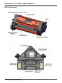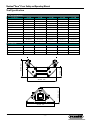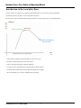
1
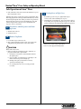
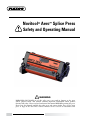
Novitool® Aero™ Splice Press Safety and Operating Manual WARNING IMPROPER OR UNSAFE use of this splice press can result in damage to the press and/or physical harm. This manual contains important information about product function and safety. Please read and understand this manual BEFORE operating the press. Please keep this manual available for other users and owners before they use the Aero press. A copy of the Aero Press Owner’s Manual can be accessed on www.flexco.com. XXXnFYDPDPNtQIPOF —2— Novitool® Aero™ Press Safety and Operating Manual Table of Contents Main Components...................................................................................pg. 4 Tool Specifications....................................................................................pg.5 Introduction to the Aero™ Splice Press ............................................. pg. 6-7 Flight Case ................................................................................................pg. 8 General Safety Rules................................................................................pg. 8 Safe Operation of Aero™ Press .........................................................pg. 9-15 Technical Assistance ..............................................................................pg.16 Electrical Diagram of the Power Supply Cables ..........................pg. 16-17 Electrical Schematics ......................................................................pg. 18-21 Maintenance ...........................................................................................pg. 22 Logbook ..................................................................................................pg. 23 EC Declaration of Conformity ............................................................pg. 24 —3— Novitool® Aero™ Press Safety and Operating Manual Main Components XXXnFYDPDPNt5FM —4— Novitool® Aero™ Press Safety and Operating Manual Tool Specification Aero™ Tool Specifications Specifications Aero 300 Aero 600 Aero 900 Aero 1200 Aero 1500 Effective splice length 305 mm / 12 ” 610 mm / 24 ” 914 mm / 36 ” 1219 mm / 48 ” 1524 mm / 60 ” Effective splice width 120 mm / 4.7 ” 120 mm / 4.7 ” 120 mm / 4.7 ” 120 mm / 4.7 ” 120 mm / 4.7 ” Weight lower part 10 kg / 22 lbs 15 kg / 33 lbs 20 kg / 44 lbs 25 kg / 55 lbs 30 kg / 66 lbs Weight upper part 11 kg / 24 lbs 15 kg / 33 lbs 18 kg / 40 lbs 22 kg / 48 lbs 26 kg / 57 lbs Total weight 21 kg / 46 lbs 30 kg / 66 lbs 38 kg / 84 lbs 47 kg / 104 lbs 56 kg / 123 lbs Length 505 mm / 19.9 ” 805 mm / 31.7 ” 1105 mm / 43.5 ” 1405 mm / 55.3 ” 1705 mm / 67.1 ” Overall Height 220 mm / 8.5 ” 220 mm / 8.5 ” 220 mm / 8.5 ” 220 mm / 8.5 ” 220 mm / 8.5 ” 2 Bar / 28 PSI 2 Bar / 28 PSI 2 Bar / 28 PSI 2 Bar / 28 PSI 2 Bar / 28 PSI Max. temperature 200 ˚C / 390 ˚F 200 ˚C / 390 ˚F 200 ˚C / 390 ˚F 200 ˚C / 390 ˚F 200 ˚C / 390 ˚F 770 x 370 x 310 mm (30 x 15 x 12 ”) 1070 x 370 x 310 mm (42 x 15 x 12 ”) 1370 x 370 x 310 mm (54 x 15 x 12 ”) 1726 x 370 x 310 mm (68 x 15 x 12 ”) 1926 x 370 x 310 mm (76 x 146 x 122 ”) 26 kg / 57 lbs 35 kg / 77 lbs 43 kg / 95 lbs 1 phase 230 Vac 8.8 A 14 A 16 A 3 phase 230 Vac 4.4 A 7A 8A 3 phase 400 Vac+0 4.4 A 7A 3 phase 460 Vac 4.4 A 7A Dimensions for transport (L x W x H) Weight for transport 135 mm - 5.3" Max. pressure 53 kg / 117 lbs 61 kg / 134 lbs U.S. only 30 A U.S. only 30 A 12 A 15 A 8A 12 A 15 A 8A 12 A 15 A Power requirements 83 mm - 3.3" 140 mm - 5.5" 250 mm - 9.8" 135 mm - 5.3" 250 mm - 9.8" —5— - 3.3" 40 mm - 5.5" 250 mm - 9.8" Novitool® Aero™ Press Safety and Operating Manual Introduction to the Aero Splice Press The Aero™ splice press is an all-in-one solution for splicing thermoplastic conveyor belts (e.g. PVC, polyurethane). No external control box, air pump, or water cooling tank are required. temperature The Aero presses are provided with electric heating and built in air cooling. The splice process runs fully automated. Settings: splice temperature dwell time cool down temperature (fans turn off) time (graph of the basic process, program level 1) r 4QMJDFQSFTTVSFJTBQQMJFECZBOJOUFSOBMDPNQSFTTPSNBYCBSQTJ r )FBUTVQUPBTQMJDFUFNQFSBUVSFPGNBY$' r ,FFQTJUBUUIFTQMJDFUFNQFSBUVSFBEKVTUBCMFEXFMMUJNF r $PPMTEPXOUPUIFDPPMJOHUFNQFSBUVSFTBGFUFNQFSBUVSFUPUBLFUIFCFMUPVU r 'PSUIJDLFSCFMUTBQSFIFBUUFNQFSBUVSFBOEQSFIFBUEXFMMUJNFDBOCFBQQMJFE r ѮFCPUUPNIFBUJOHDBOCFTFUMPXFSPSIJHIFSUIBOUIFUPQIFBUJOH XXXnFYDPDPNt5FM —6— Novitool® Aero™ Press Safety and Operating Manual Introduction to the Aero™ Splice Press temperature * If the belt is relatively thick a problem might occur where the outside of the belt is at the splicing temperature too long, waiting for the inside to reach the required temperature. Melted material might flow away or discolor and fabrics might shrink. To avoid this problem, UIFQSFIFBUPQUJPODBOCFVTFEѮJTPQUJPOIFBUTUIFCFMUVQPVUTJEFBOEJOTJEF UPBUFNQFSBUVSFKVTUCFMPXUIFNFMUJOHUFNQFSBUVSF After the preheat stage, the inside splice temperature can be reached much quicker, minimizing the risk for unwanted flow of material, discoloring or fabric shrinkage. Settings: splice temperature dwell time pre-heat temperature pre-heat dwell time cool down temperature (fans turn off) time (graph of a procss with prehating, program level 2) ** The reading of the display relates to the top temperature of the press. If more or less heat is required at the bottom of the belt, the “bottom heat factor” can be used. Please note that this factor relates to a plus or minus amount of heat (%), not to a specific temperature. —7— Novitool® Aero™ Press Safety and Operating Manual Flight Case 1. Aero™ presses are supplied with a flight case for both storage purposes and also for easy transport to POTJUFKPCT Press End with Power Receptacles Storage Compartment 2. Place press in the flight case so the end with the power receptacles is facing the storage compartment. This will protect the receptacles from damage when transporting. 3. 'MJHIUDBTFTGPSUIF"FSPIBWFUXPXIFFMT "FSPBSFQBDLBHFEJOëJHIUDBTFTXJUIGPVS wheels and an extension handle. Extended handle 4. Flight cases can be stacked on top of each other, but need to be secured during transportation. 5. "FSPëJHIUDBTFTGFBUVSFBOFYUFOEFE handle for ease and convenience in transport. Click in the grip of the flight case to release the handle. General Safety Rules –Save These Instructions– OVERALL SAFETY RULES ! DANGER Signal words: 5P"WPJE4FWFSF1FSTPOBM*OKVSZPS1SPQFSUZ Damage, read carefully and understand the following Safety Precautions. “DANGER” indicates an imminently hazardous situation which, if not avoided, will result in EFBUIPSTFSJPVTJOKVSZѮFTJHOBMXPSEJT limited to the most extreme situations. ! DANGER “WARNING” indicates a potentially hazardous situation which, if not avoided, could result in EFBUIPSTFSJPVTJOKVSZ Terminate electrical hazards by removing power cord from wall receptacle or machine base inlet. “CAUTION” indicates a potentially hazardous situation which, if not avoided, may result in NJOPSPSNPEFSBUFJOKVSZ*UNBZBMTPCFVTFE to alert against unsafe practices. ! WARNING Terminate pressure related hazards by pressing the red pressure relief button. Safety Symbol ! CAUTION ! Press platens develop over 5 tons of clamping force. When operating the press keep the four press connector bolts in place by hand tightening. This international safety symbol is used to identify and call attention to specific safety matters. ! CAUTION Safety Information 5P"WPJE4FWFSF1FSTPOBM*OKVSZPS1SPQFSUZ Damage, read carefully and understand the following Safety Precautions. XXXnFYDPDPNt5FM Avoid temperature related hazards by handling press components and belt once safely cooled. —8— Novitool® Aero™ Press Safety and Operating Manual Safe Operation of Aero™ Press 1. ! Locate a position in facility where appropriate voltage and power receptacles are available to operate the Aero press. ii. Second, insert plug end into wall receptacle. WARNING Operating the press on incorrect voltage can cause serious damage and potential hazards. The following Aero power cords are available: B WPMUTJOHMFQIBTF C WPMUUISFFQIBTF D WPMUUISFFQIBTFOFVUSBM E WPMUUISFFQIBTF 2. ! ! Visually inspect power cord: iii. NEVER leave power cord plugged into wall while detached from unit as this could lead to a serious electrical danger if it comes in contact with fluids, such as water. DANGER ! a. Inspect cord for damage. Do not use power cord in a damaged state. Either replace cord or have an electrician remove damaged section and reattach plug. Electrician must refer to electrical diagram on pages 16 and 17 for proper attachment. b. Confirm compatibility between plug end and power receptacle. If incorrect, find alternate power source or have electrician apply correct plug, referring to electrical diagram on pages 16 and 17. ! DANGER DANGER d. All press power inlets and cable connectors have been supplied with keyed (patterned) guide pins and bushings. This keying will prevent incorrect connection. Do NOT alter or remove guide pins or bushings. DANGER c. DO NOT plug power cord into wall receptacle at this time. Later in the operation, when ready to connect power follow these safe and proper operating procedures: i. First, plug power cord into machine base power inlet. 3. ! Remove press from flight case. HEAVY OBJECT /PUF6TFQSPQFSMJѫJOHUFDIOJRVFTUPBWPJEQFSTPOBMJOKVSZBTL for assistance for removal from flight case if press is heavier than you are comfortable handling by yourself. 4. ! Visually inspect press for damage. WARNING Broken or missing components can cause an unsafe working environment and will likely cause additional damage to press and QPTTJCMFCPEJMZJOKVSZ —9— Novitool® Aero™ Press Safety and Operating Manual Safe Operation of Aero™ Press ! 7. DANGER a. Ensure all four press connector bolts are in good condition. Do NOT attempt to operate the press if a bolt is broken or missing. b. Inspect platens for potential damage. c. Ensure platens are free of dirt/debris. If dirty, follow these cleaning instructions: a. Lay clean silicone pad over clean bottom platen. Use care to MBZTJMJDPOFQBEëBUXSJOLMFTJOTJMJDPOFQBEXJMMJNQBDUUIF finished appearance of the splice. Silicone pads are used to prevent belt material from sticking to the platens of the press. b. Lay prepared belt ends on the bottom platen. /PUFѮFIFBUFE[POFJTJOUIFDFOUFSNNXJEUIPGUIF QMBUFOPVUTJEFPGUIJTBSFBUIFQMBUFOTBSFJOUIFJOUFHSBUFE cool zones. Be sure splice area is centered properly. There is some ‘heat loss’ on the outside areas of the heated zone, which is dependent upon the belt type. Typically the ‘melt zone’ is BQQSPYJNBUFMZNN1SFQBSFEêOHFSTQMJDFBOEPSQMZ separation must be within the ‘melt zone’, as material outside of the melt zone will not become molten. i. Use ammonia based cleaners with clean towel to gently remove dirt/debris. ! WARNING ii. Do NOT clean platens with a flammable solution. ! Insert prepared belt ends into the press: CAUTION iii. Do NOT use water to hose down the Aero press. If press needs to be cleaned, use ammonia based solvent applied to a cloth and wipe down press. Dry press with clean dry cloth. d. Inspect all cables to ensure they are in good condition. If they are damaged, do NOT use press until they are replaced. 5. Visually inspect silicone pads. Visually inspect silicone pads. Pads should be free of dirt/debris in order to obtain a quality finished splice. Pads can also be cleaned using ammonia based cleaning solution that is NONFLAMMABLE and will not cause an adverse reaction with the splice. 6. c. Ensure prepared belt ends are tight together. If installing a finger splice, make sure that the finger tips are fully meshed XJUIPVUHBQTCFUXFFOUPQBOECPUUPNPGUIFêOHFST)FBUUBDL in place if needed. E *GêMNGPJMJTOFFEFEGPSUIFTQMJDFBQQMZUPQSFQBSFECFMUFOE e. It is important to use ‘bumpers’. Bumpers prevent the melted material from flowing outside of the belt width and also provide stability in the press. Remove top beam: a. Loosen all four press connector bolts. b. Using top beam handles located on end caps, remove top beam from press. ! ! HEAVY OBJECT Depending upon width and weight of the press you have, you may require assistance from another person. c. Place beam on side, do not place the beam with the platen facing down. It is important to keep platens in good working condition. Resting the beam on the side will protect the platens from scratching or from getting dirty. Beams have rubber stripping along the length of the press to protect from scratching (see photo). XXXnFYDPDPNt5FM CAUTION The bumpers must be to a width that will fill the balance of the press to ensure even pressure and prevent damage to the press. f. Install clamp bars, ensuring that fingers remain tightly meshed. g. Lay clean silicone pad over the prepared splice, using care to avoid wrinkles in the silicone pad. —10— Novitool® Aero™ Press Safety and Operating Manual Safe Operation of Aero™ Press 8. ! Install top beam: JJ1SFTTJTDBQBCMFPGQSPEVDJOHBGPSDFVQUPQPVOET / %P/05PQFSBUFUIFQSFTTXJUIBNJTTJOHPSCSPLFO bolt as this can cause serious physical harm and/or damage to press. If a bolt is missing or broken, replace with authorized factory parts only. ! 9. 10. DANGER Connect umbilical power cable from top beam to bottom beam: a. Insert umbilical power cable connector into machine base umbilical cable connector. b. Engage latch to lock plug in place. Forgetting to latch plug can result in intermittent power supply to press base controls. b. With the top beam properly centered, rotate all four press connector bolts up and hand tighten, ensuring bolts are seated properly in spherical recess on top beam. ! Remove belt clamps after top beam is secured: Failure to remove clamps may result in incomplete melt zone at ends of splices that are full press width. HEAVY OBJECT If weight and length of top beam is difficult to handle by yourself, enlist assistance of another person. J"FSPBOENPEFMTJODMVEFBêYUVSFUPBJEJO sliding top beam in place if access to position beam is difficult. Install fixture in slots of end caps. Slide top beam the length of the tool. Lift end to remove fixitive. ! WARNING iii. To ensure proper thread engagement, the prepared belt FOETJODMVEJOHWBSJPVTQBET DBOOPUFYDFFENNu This does not necessarily relate to the press’ heating capability. Exceeding this thickness will not allow sufficient thread engagement of the Connecting Bolts to ensure safe clamping of the press, and can result in damage to the press and personal danger. B $BSFGVMMZQPTJUJPOUPQCFBNPOUPQSFQBSFECFMUFOET avoid disrupting prepared belt ends and possibly separating the fingers. ! DANGER CAUTION i. Do not allow users to get fingers caught in potential pinch points. —11— Novitool® Aero™ Press Safety and Operating Manual Safe Operation of Aero™ Press 11. ! Connect power cord to press: d. Next, insert power cable plug into the appropriate wall receptacle. WARNING It is extremely important that the power cord is attached to the press first and then to the wall receptacle. Reversing these procedures can put personnel at risk of electrocution and may cause a damaging electrical arc. a. Insert power cable connector to the machine base power outlet. ! DANGER e. User wiring of electrical plug to bare power cable end or hard XJSJOHDBCMFUPKVODUJPOCPY.645CFJOBDDPSEBODFXJUIUIF ‘Electrical Diagram of Power Supply Cable’ on pages 16 and 17. Ensure proper cable diagram is used for cable being wired. Ensure the correct plug is used. Only qualified personnel should perform this activity. The Aero press has 2 controllers: 1. The temperature controller located on the top beam has two levels of programming: a. Level 1 Programming: Splice temperature NBY$' TQMJDFEXFMMUJNFDPPMEPXO temperature. b. Level 2 Programming: Preheat temperature, preheat dwell time, bottom heat factor (lower or higher than top platen heating), cool down temperature, and units (Centigrade or Fahrenheit). 2. The pressure controller is located on the bottom beam and controls the pressure up to 2 bars/28 psi. b. Engage latch to lock plug in place. Forgetting to lock plug can result in intermittent power supply to the press. 12. ! Connect the Aero™ press to the power supply. The following parameters can be set: a. Controller on top part of the Aero i. Input level 1 r 4QMJDFUFNQFSBUVSFNBY$' r 4QMJDFUFNQFSBUVSFEXFMMUJNF r $PPMEPXOUFNQFSBUVSF ii. Input level 2 r 1SFIFBUUFNQFSBUVSF r 1SFIFBUEXFMMUJNF r 4QMJDFUFNQFSBUVSF r 4QMJDFUFNQFSBUVSFEXFMMUJNF r $PPMEPXOUFNQFSBUVSF r #PUUPNIFBUGBDUPSMPXFSPSIJHIFSUIBOUPQIFBUJOH b. Controller on bottom part of the Aero J 4QMJDFQSFTTVSFNBYCBSQTJ DANGER c. Double check to ensure the voltage and receptacle is appropriate for the power cable you are using. Incorrect, excessive power voltage can cause serious damage to press and also present QIZTJDBMEBOHFSJFWPMUPVUMFUGFFEJOHJOUPBWPMUDBCMF could cause a short circuit and/or fire). Note cable voltage requirement XXXnFYDPDPNt5FM Setting Splice Parameters: —12— Novitool® Aero™ Press Safety and Operating Manual Safe Operation of Aero™ Press Additional temperature and dwell time settings: Changing to Level 2 programming: Setting of the splice temperature r 1VTICVUUPOBOEIPMECVUUPO until display shows “LEv1”. r 1VTIUIF61 button once and display shows “LEv2”. r 1SPHSBNMFWFMTFUUJOHTBSFBWBJMBCMFOPX 4FUUJOHQSFIFBUUFNQFSBUVSFEFGBVMUWBMVF$ r 1VTICVUUPO . The first value which is shown on the EJTQMBZJTUIFQSFIFBUUFNQFSBUVSF13&)5 r $IBOHFBDUVBMTFUUJOHCZQVTIJOH61 or DOWN button. r 8BJUGPSPOFTFDPOEBOEEJTQMBZFEWBMVFCMJOLTUP confirm that it is set. r .BYJNVNQSFIFBUUFNQFSBUVSFJTMJNJUFEJO DPOUSPMMFSUP$' 4FUUJOHQSFIFBUEXFMMUJNFEFGBVMUWBMVFTFD r 1VTICVUUPO VOUJMEJTQMBZTIPXTi13&)%u r 1VTI61 or DOWN CVUUPOUPBEKVTU dwell time. r 8BJUGPSPOFTFDPOEBOEEJTQMBZFEWBMVFCMJOLTUP confirm that it is set. Note: Splice temperature, splice dwell time, and cool down temperature will remain in effect from Level 1 programming.. The Eurotherm controller defaults at start up to Level 1 programming. All settings are presented as an abbreviation, e.g. “SPL.T”. If you wait a moment a readable text is shown, e.g. “Splice Temperature”. Level 1 Input: a. Setting Basic Temperature and Dwell Time Inputs. i. Setting of the splice temperature r 1VTICVUUPO . The first value shown is splice temperature (SPLT). r $IBOHFUIFBDUVBMTFUUJOHCZQVTIJOHUIF61 or DOWN button. r 8BJUGPSPOFTFDPOEBOEUIFEJTQMBZFEWBMVFCMJOLTUP confirm that it is set. r .BYJNVNUFNQFSBUVSFJTMJNJUFEUP$' ii. Setting splice temperature dwell time r 1VTICVUUPO until display shows “SPLDT”. r 1VTI61 or DOWN CVUUPOUPBEKVTUEXFMMUJNF r 8BJUGPSPOFTFDPOEBOEEJTQMBZFEWBMVFCMJOLTUP confirm that it is set. iii. Setting cool down temperature (when cooling fans will turn off). r 1VTICVUUPO until display shows “CLD.T”. r 1VTI61 or DOWN CVUUPOUPBEKVTUDPPMEPXO temperature. r 8BJUGPSPOFTFDPOEBOEEJTQMBZFEWBMVFCMJOLTUP confirm that it is set. r 3FUVSOUPTUBSUVQTUBUVTCZQVTIJOHCVUUPO again. Splice Pressure (bottom controller) b. Setting splice pressure r #SJFëZQVTIUIFNJEEMFCVUUPOS (display shows set value). r %0/5)0-%S BUTTON or otherwise the parameter menu will open. r 1VTI61 or DOWN CVUUPOUPBEKVTUTQMJDF pressure. r 8IFOEFTJSFEWBMVFJTTIPXOTFUCZCSJFëZQVTIJOHNJEEMF button S again. r .BYJNVNQSFTTVSFJTMJNJUFEUPCBSQTJ Setting splice temperature, splice dwell time, and cool down temperature. Setting of the bottom platen at a lower temperature (default WBMVF r 1VTICVUUPO VOUJMEJTQMBZTIPXTi#05)'u r 1VTI61 or DOWN CVUUPOUPBEKVTU percentage of power that is desired for bottom platen FHTFOEJOHPGUIFQPXFSTVQQMJFEUPUIF CPUUPNQMBUFO :PVDBOBEKVTUUPQPXFS Note: Actual bottom heat temperature cannot be input. r 8BJUGPSPOFTFDPOEBOEEJTQMBZFEWBMVFCMJOLTUP confirm that it is set. Changing from degrees Centigrade to Fahrenheit and reverse r 1VTICVUUPO until display shows “UNITS” r 1VTI61 or DOWN CVUUPOUPDIBOHFGSPN$ UP'PSSFWFSTF r 8BJUGPSPOFTFDPOEBOEEJTQMBZFEWBMVFCMJOLTUP confirm that it is set. r 3FUVSOUPTUBSUVQTUBUVTCZQVTIJOHCVUUPO again. ! ATTENTION: If the Aero is disconnected from the power supply, or the top part is disconnected from the bottom part, all extra settings of level 2 return to their default value. Only the basic TFUUJOHTBTMFWFM BOEUIFTFUUJOHGPSVOJUT$' XJMMCFLFQU —13— Novitool® Aero™ Press Safety and Operating Manual Safe Operation of Aero™ Press 13. Start Splicing Operation: ! 14. Splicing Cycle: During the splicing cycle you will be able to monitor progress by viewing the display output. Fans will start up at the end of the cook cycle to assist with fast cooling of the splice. If the fans do not start, contact Flexco for assistance. DANGER Before initiating splicing cycle, confirm all four press connector bolts are engaged with top of press and are hand-tight. Depress green ‘Start’ button. Air compressor will start and you will be able to view status of splicing cycle by watching digital display on control panel. Air pressure will continue to build after the compressor stops. 15. Release Pressure: After splicing cycle is complete, depress the red pressure relief valve button until the pressure is fully relieved. Start button Note: It is common for the air pressure to continue to rise beyond input value. This is due to the effect of the heat generated by press causing additional expansion in air bladder. ! WARNING Although press remains fairly cool during entire splice cycle, it is wise to avoid touching press during heating and cooling down process. ,FFQêOHFSTDMFBSPGBOZQPUFOUJBMQJODIQPJOUTFTQFDJBMMZXIFSF beams have temporarily deflected during the splicing cycle, as they will return to their normal state when pressure is relieved. Note: The Aero has been optimized for process speed, portability and ease of use. A resulting affect of the designed portability of the press is that the structure will deflect as internal air pressure is increasing during the splicing process. The length of the press will determine how much deflection will occur at any specific pressure. Beam extrusions were designed with strength to return to UIFJSOPSNBMTUBUFXIFOQSFTTVSFJTSFMJFWFEEFëFDUJPOXJMMOPUCF permanent. 16. Disconnect main power cable: ! ! a. It is critical to remove the power cord from the wall receptacle first. WARNING ,FFQêOHFSTDMFBSPGEFëFDUFECFBNT ! CAUTION The Aero press does not have an ‘Emergency Stop’ button. If there is a need to stop the press mid-cycle, then disconnect the press from power source and allow press to cool. NOTE: Temperature cycle may be aborted by simultaneously pressing and holding the and buttons. XXXnFYDPDPNt5FM DANGER —14— Novitool® Aero™ Press Safety and Operating Manual Safe Operation of Aero™ Press b. Next, unlatch the cable connector from the machine base power inlet and gently disconnect. 19. Packing Press in Flight Case: Following this sequence is critical for operator and bystander safety. Removing plug from the wall receptacle first eliminates any current from flowing through the cable. If this procedure is not performed first and the cable connector is removed initially, the power cable remains energized and could cause serious and fatal shock if exposed to water or other fluids. a. Reassemble top beam onto press, tighten all four press connector bolts, and install clamp bars on press. b. Carefully place press in flight case. Note: Press must be placed in case with power receptacles facing the storage area. This will protect receptacles from getting damaged during transportation. 17. Disconnect umbilical power cord from top beam: Press End with Power Receptacles a. Unlatch cable connector. b. Gently disconnect. Storage Compartment 18. Remove Top Beam: a. Loosen all four press connector bolts. C -JѫUPQCFBNPĒBOEQMBDFCFBNPOTJEFEPOPUQMBDFCFBN with platens facing downward in contact with a surface. ! c. Place power cords in storage compartment. d. Close case and engage the locking latches. CAUTION Platen surfaces may be hot. c. Remove top silicone pad and inspect splice. Elements of a properly installed endless splice include: i. Limited but consistent flow of PVC/Urethane material through the splice. ii. Proper bonding, especially at the tips of the fingers. ‘Pin )PMFTTIPVMEOPUCFQSFTFOUBUêOHFSUJQT JJJ #FOEJOHPGUIFTQMJDFKPJOUTIPVMEOPUDSFBUFBOZ separation at the finger edges. iv. No scorching of the belt cover or bottom ply should be evident. —15— Novitool® Aero™ Press Safety and Operating Manual Electrical Diagram of the Power Supply Cables Technical Assistance Contact Flexco’s Customer Service if technical assistance or repair parts are needed.: www.flexco.com XXXnFYDPDPNt5FM —16— Novitool® Aero™ Press Safety and Operating Manual Electrical Diagram of the Power Supply Cables Three phase cables —17— Novitool® Aero™ Press Safety and Operating Manual Electrical Schematics TEMPERATURE REGULATOR 1 2 3+ RED .75mm2 RED/WHITE .75mm2 BLACK RED/WHITE .75mm2 RED/WHITE WHITE AA 1B AB 2A 24V+ 2BV+ 24VC V- WHITE .75mm2 WHITE .75mm2 RED .75mm2 WHITE .75mm2 LA 14 START S1 13 WHITE .75mm2 BLACK 1.5mm2 BLACK 1.5mm2 RED/WHITE 4- BLACK 1.5mm2 BLACK 1.5mm2 BLACK 1.5mm2 WHITE 1.5mm2 SOLID STATE RELAY 1A YELLOW/GREEN 1.5mm2 REAR PLATE HEATER PAD WHITE 2 3 4 5 6 7 8 9 10 230V WHITE RED P2 PINS 1 BLACK 1.5mm2 BLACK 1.5mm2 BLACK 1.5mm2 BLACK 1.5mm2 BLACK 1.5mm2 BLACK 1.5mm2 YELLOW/GREEN 1.5mm2 YELLOW/GREEN 1.5mm2 XXXnFYDPDPNt5FM RED/WHITE .75mm2 RED .75mm2 WHITE .75mm2 —18— YELLO YELLOW/ GREEN 2.5mm2 Novitool® Aero™ Press Safety and Operating Manual RED .75mm2 RED .75mm2 A1 3 R1 RELAY 24 START S1 23 FANS OW/GREEN 1.5mm2 1 YELLOW/GREEN 1.5mm2 YELLOW/GREEN 1.5mm2 YELLOW/GREEN 1.5mm2 FRAME 2 SPLICE PLATE GRID PLATE 3 —19— WHITE .75mm2 4 RED .75mm2 WHITE .75mm2 A2 Novitool® Aero™ Press Safety and Operating Manual Electrical Schematics RED .75mm2 RED .75mm2 BLACK 1.5mm2 BLACK 1.5mm2 + L1 1 SOLID STATE RELAY 3+ RED .75mm2 BLACK 1.5mm2 BLACK 1.5mm2 - BLACK 1.5mm2 WHITE .75mm2 BLACK 1.5mm2 BRIDGE CELL BLACK 1.5mm2 L2 PE BLACK 1.5mm2 0V 0V - - BLACK 1.5mm2 POWER SUPPLY BLACK 1.5mm2 YELLOW/GREEN 1.5mm2 YELLOW/GREEN 1.5mm2 YELLOW/GREEN 1.5mm2 WHITE 1.5mm2 YELLOW/GREEN 2.5mm2 YELLOW/GREEN 1.5mm2 YELLOW/GREEN 1.5mm2 WHITE .75mm2 BLACK 1.5mm2 HEATER PAD WHITE 1.5mm2 BLACK 1.5mm2 BLACK 1.5mm2 BLACK 1.5mm2 BLACK 1.5mm2 RED 1.5mm2 BLACK 1.5mm2 BLUE 1.5mm2 BLACK 1.5mm2 YELLOW/GREEN 1.5mm2 TB1 P1 1 2 3 4 5 6 7 8 9 10 YELLOW/GREEN 1.5mm2 1 2 3 4 5 6 7 8 9 10 FRAME PINS POWER SUPPLY XXXnFYDPDPNt5FM —20— SPLICE PLATE WHITE .75mm2 + + 24V24V A1 4 A2 PRESSURE REGULATOR MAX: 2 BAR 14 1 10 3 9 11 12 TB1 7 6 8 9 10 P2 —21— 13 1 3 2 4 5 SOCKET BROWN .25mm2 BLUE .25mm2 WHITE WHITE .75mm2 RED .75mm2 BLUE .25mm2 RED .75mm2 BROWN .25mm2 WHITE .75mm2 BLACK .25mm2 RED .75mm2 FAN 1 WHITE .75mm2 FAN 2 RED .75mm2 4RELAY BLACK 1.5mm2 3 RED/WHITE .75mm2 R1 WHITE .75mm2 2 WHITE .75mm2 WHITE .75mm2 WHITE .75mm2 RED .75mm2 BLACK 1.5mm2 Novitool® Aero™ Press Safety and Operating Manual WHITE .75mm2 COMPRESSOR Novitool® Aero™ Press Safety and Operating Manual Maintnenance Settings of the pressure controller: Calibration of the pressure controller Resetting of the parameters to their original settings: r 5BLFDBSFUIBUUIFQSFTTVSFJOUIF"&30JTDPNQMFUFMZ released r 1VTIBOEIPMEUIFS button to get into the function NFOVEJTQMBZTIPXTi'uOPX r 1VTIUIFS CVUUPOPOFNPSFUJNFUPHFUJOUPUIF'NFOV (unit conversion menu) –The display should show “Uni” and “bAr” (bar) or “Psi” (psi) now. Setting can be done by pushing the UP or DOWN button r 1VTIS button to return to the function menu (display TIPXTi'u r 1VTIUIF61 button to get to “F1” –(push S iP6uTIPVMECFTFUUPi):4u –(push S) “lot” should be set to “I-n” –(push S iO*uTIPVMECFTFUUPiu –(push S i)*uTIPVMECFTFUUPiu –(push S) “Col” should be set to “Sor” r ' OPUVTFE r ' iS&4uTIPVMECFTFUUPiu r *GUIFSFBEJOHPOUIFEJTQMBZJTEJĒFSFOUUIBO[FSPDPOUJOVF as follows: –Push both the UP and DOWN button simultaneously and hold them for a while mѮFQSFTTVSFDPOUSPMMFSJTDBMJCSBUFEUP[FSPUIF EJTQMBZTIPXTiuOPX Reset of the 24 VDC fuse r 0OUIFGSPOUPGUIFQBOFMUIFSFJTBCVUUPOi'uUPSFTFUUIF 24 VDC fuse r ' iES&uTIPVMECFTFUUPiu r ' i1SuTIPVMECFTFUUPiP''u r ' OPUUPCFDIBOHFE r ' i&$PuTIPVMECFTFUUPiP''u r ' i1JOuTIPVMECFTFUUPiP''u r ' i"--uTIPVMECFTFUUPiP''u r ' i$PQZuTIPVMECFTFUUPiP''u –If in the copy mode, push the and buttons simultaneously for some seconds to return r ' iU&4UuTIPVMECFTFUUPi"u r ' iJOJuTIPVMECFTFUUPiP''u r 1VTIBOEIPMEUIFS button to return to the operation mode XXXnFYDPDPNt5FM —22— Novitool® Aero™ Press Safety and Operating Manual Logbook DATE NOTES DATE —23— NOTES EC Declaration of Conformity Flexco Netherlands 3PPTXJKLXFH .)7FMTFO/PPSE The Netherlands www.novitool.com 8F'MFYDP/FUIFSMBOETEFDMBSFUIBUUIFTQMJDFQSFTTFT"FSP"FSP"FSP"FSPBOE"FSP for splicing thermoplastic conveyor belt material, comply with the following EC Directives: r .BDIJOF4BGFUZ%JSFDUJWF&$ r -PX7PMUBHF&RVJQNFOU%JSFDUJWF&$ r &MFDUSPNBHOFUJD$PNQBUJCJMJUZ%JSFDUJWF& The Netherlands, Velsen-Noord, 0DUPCFS J.S. van’t Schip 8JTDPOTJO"WFOVFt%PXOFST(SPWF*-64" 5FMt'BYt&NBJMJOGP!nFYDPDPNt8FC www.flexco.com "VTUSBMJBt$IJOBt&OHMBOEt(FSNBOZ *OEJBt.FYJDPt4JOHBQPSFt4PVUI"GSJDB ª'MFYJCMF4UFFM-BDJOH$PNQBOZ'MFYDP®JTBSFHJTUFSFEUSBEFNBSL'PS3FPSEFS9