1
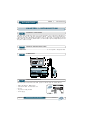
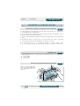
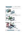
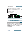
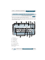
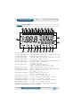
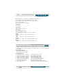
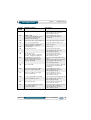
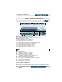
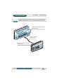
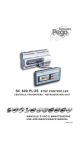
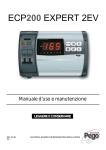
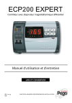
SC 600 PLUS
INDEX
INTRODUCTION
Page 22
Page 22
Page 22
Page 22
1.1
1.2
1.3
1.4
CHAP. 1
General features
Product identification code
Dimensions
Identification data
INSTALLATION
Page 23
Page 23
Page 23
Page 24
2.1
2.2
2.3
2.4
CHAP. 2
Important general information for the installer
Kit for mounting
Installing the Master control board
Installing the Plus SC 600 console
FUNCTIONALITY
Page 25
3.1
CHAP. 3
Functions controlled by the PLUS SC 600
TECHNICAL SPECIFICATIONS
Page 26
Page 26
4.1
4.2
PARAMETERS PROGRAMMING
Page 27
Page 28
Page 29
Page 30
Page 30
Page 30
Page 31
Page 31
Page 32
Page 32
Page 33
5.1
5.2
5.3
5.4
5.5
5.6
5.7
5.8
5.9
5.10
5.11
6.1
6.2
6.3
6.4
6.5
6.6
CHAP. 6
Operation
Compressor activation/deactivation conditions
Fan activation/deactivation conditions
Operation “without rotation”
Operation “with rotation”
Expandability of the PLUS SC 600 system
DIAGNOSTIC
Page 36
Page 37
Page 37
CHAP. 5
PLUS SC 600 control panel
Lcd display
Master control board
General features
Key to symbols
PLUS SC 600 system parameters
Programming and display of pressure setpoint
First programming level (User)
List of 1st level variables (User)
Second programming level (Installer)
List of 2nd level variables (Installer)
DESCRIPTION OF OPERATION
Page 34
Page 34
Page 34
Page 34
Page 35
Page 35
CHAP. 4
Technical specifications
Warranty conditions
7.1
7.2
7.3
CHAP. 7
Alarms management
Alarms database
Troubleshooting
APPENDICES
Page 38
Page 39
Page 40
A.1
A.2
A.3
EC Declaration of conformity
Master card terminal block
Connection between Console Plus SC 600 and the Master control board
Rev. 01-04
MAINTENANCE AND USE MANUAL
Pag. 21
C H A P. 1 - I n t r o d u c t i o n
SC 600 PLUS
CHAPTER 1: INTRODUCTION
G E N E R A L F E AT U R E S
1.1
The SC600 PLUS system allows users to control the machine room of a refrigeration plant in which
there is more than one compressor. It guarantees uniform operation and proper distribution of
operating times among individual machines.All functions are performed in complete safety and the
SC600 PLUS Control Console (LCD DISPLAY) can be installed anywhere, independently of where
the power cabinet is located.
1.2
PRODUCT IDENTIFICATION CODE
SC 600 PLUS .................................................................................................................................................. Control system for refrigeration units.
1.3
DIMENSIONS
98
110
210
35
114
180
69
214
1.4
IDENTIFICATION DATA
The unit described in this manual has an ID plate on its side showing the relevant ID data:
• Name and address of Manufacturer
• Code and model of the electrical board
• Serial n°
• IP protection rating and date
• Power supply
PEGO s.r.l
PROGETTAZIONE - COSTRUZIONE QUADRI ELETTRICI
PER LA REFRIGERAZIONE
OCCHIOBELLO (ROVIGO)
TEL. +39 0425 762906 FAX +39 0425 762905
OGGETTO: D-ECP200T/Q
MATRICOLA: QE-P2001400
GRADO DI PROTEZIONE IP: 55
DIRETTIVE: 89/392 89/336-73/23
QE-P2001400
Pag. 22
MAINTENANCE AND USE MANUAL
DATA: 03.06.2002
TENSIONE ALIMENTAZIONE: 230V-50HZ
NORME RIF.: CEI EN 60204/1
Rev. 01-04
AUX:
230V
C H A P. 2 - I n s t a l l a t i o n
SC 600 PLUS
CHAPTER 2: INSTALLATION
IMPORTANT GENERAL INFORMATION FOR THE USER
2.1
1. Install the device in places where the protection rating is observed and try not to damage the
box when drilling holes for wire/pipe seats.
2. Do not use multi-polar cables in which there are wires connected to inductive/power loads or
signalling wires (e.g. probes and digital inputs).
3.
Do not fit power supply wiring and signal wiring (probes and digital inputs) in the same raceways
or ducts.
4. Minimise the length of connector wires so that the wiring does not have a spiral shape.
5. Place a general protection fuse upstream from the electronic controller.
6. All
wiring must be of a cross-section suitable for relevant power levels.
7. When it is necessary to extend the probes, the wires must have a cross-section of at least 1 mm2.
ASSEMBLY KIT
2.2
The PLUS SC 600 electronic controller features, for assembly and use, the following:
• N° 1 fixing bracket;
• N° 1 phone cable;
• N° 1 user manual.
INSTALLING THE MASTER CONTROL BOARD
2.3
Fig. 1 : Position the MASTER
board in the din guide and insert
the four plugs to fix the box to
the panel.
Rev. 01-04
MAINTENANCE AND USE MANUAL
Pag. 23
C H A P. 2 - I n s t a l l a t i o n
SC 600 PLUS
Fig. 2
: Main MASTER control board
components
2.4
INSTALLING THE PLUS SC 600 CONSOLE
Fig. 3
parts.
SCHEDA MASTER
PHONE CABLE
: Main PLUS SC 600 control console
: Example of PLUS SC 600
installation.
Fig. 4
PLUS SC 600
Pag. 24
MAINTENANCE AND USE MANUAL
Rev. 01-04
C H A P. 3 - F u n c t i o n a l i t y
SC 600 PLUS
Effect all electrical connections as illustrated in the diagram for the corresponding model
(see relative table in APPENDICES).
To effect correct electrical connection and maintain the protection rating, use lead
grippers and/or duct grippers to ensure a good seal.
Route the wiring inside the unit in as tidy a fashion as possible: be especially careful to keep power
wires away from signal wires. Use clips to hold wires in place.
Be careful not to over-tighten the closure screws as this could warp the box and compromise proper operation of the membrane-type keypad..
Before doing any maintenance work disconnect the power supply from the board; this ensures that
the operator is able to work safely.
Fig. 5:
Components layout.
CHAPTER 3: FUNCTIONALITY
FUNCTIONS CONTROLLED BY THE PLUS SC 600
3.1
The SC600 PLUS system consists of two distinct parts, the Control Console (LCD DISPLAY) and
the MASTER control board: these two parts are interconnected by a standard telephone lead.
The Control Board, installed inside an electrical cabinet, enables switching on and switching off of
the compressors.
The Control Console allows the user to set up and control the system as desired.
It can be installed several tens of metres from the Master control board and used as a remote
control unit with the aid of a simple telephone lead.
The PLUS SC 600 STEP CONTROLLER system features the following functions:
• Display and adjustment of parameters (high/low pressure SET)
• Stand-by activation/deactivation
• System alarms signals/display
• Adjustment of compressor and fan status
• Clock function.
Rev. 01-04
MAINTENANCE AND USE MANUAL
Pag. 25
SC 600 PLUS
C H A P. 4 - Te c h n i c a l c h a r a c t e r i s t i c s
CHAPTER 4: TECHNICAL CHARACTERISTICS
4.1
TECHNICAL CHARACTERISTICS
POWER SUPPLY
Voltage
Max power
230 V~ ± 10% 50Hz
~ 8 VA
AMBIENT CONDITIONS
Operating temperature
Storage temperature
Relative ambient humidity
-10 ÷ 60°C
-30 ÷ 70°C
Below 90%
GENERAL CHARACTERISTICS
Pressure sensor type
Measuring range
4...20 mA
-0,5...30 bar
OUTPUT CHARACTERISTICS
Outputs on relay
n° 10 Outputs on relay N.A. 16 A (AC1) 230 V AC
DIMENSIONAL CHARACTERISTICS
Dimensions Console Slim 100 (mm)
42 x 25 x 165 (HxPxL)
INSULATION AND MECHANICAL CHARACTERISTICS
Console protection rating
Console box material
IP55
self-extinguishing ABS
4.2
WARRANTY CONDITIONS
PLUS SC 600 and 100 MASTER THR electronic controllers are covered by a 12-month warranty against all manufacturing defects. If the system is used improperly the warranty will
automatically be rendered null and void. It is strongly recommended that you observe all
instructions/ information regarding the technical characteristics of the device.
WARNING !
Any modifications made to wiring and/or internal components or any tasks carried out
in a way that fails to comply with the information/instructions in this manual shall
render the warranty null and void immediately. Such modifications/tasks can also cause
serious injury or damage.
PEGO S.r.l. declines any responsibility for possible errors or inaccuracies written
in this manual as a result of printing or transcription errors.
PEGO S.r.l. reserves the right to modify its products as it deems necessary without
altering its main characteristics. Each new release of a PEGO user
manual replaces previous ones.
Pag. 26
MAINTENANCE AND USE MANUAL
Rev. 01-04
C A P. 5 - P a r a m e t e r s p r o g r a m m i n g
SC 600 PLUS
CHAPTER 5: PARAMETER PROGRAMMING
PLUS SC 600 CONTROL PANEL
5.1
The Control Console is used to program and display the parameters.
The Console can be installed directly in the machine room (e.g. power cabinet front) or in any
other position where visual control of plant operation might be useful. The Control Console
features CONTROL KEYS, INFO/WARNING ICONS and a DISPLAY which is used to program
and view all the main parameters.
2
3
6
5
4
8
7
9
1
11
10
LCD display
Compressors phase
3.
Separation phase
4.
Ventilation phase
5.
Alarm/maintenance
6.
Fans SET
7.
UP (increases value)
8.
Stand-by (stops system)
9.
Compressors SET
10. DOWN (decreases value)
11. Alarm mute
1.
2.
Rev. 01-04
MAINTENANCE AND USE MANUAL
Pag. 27
C A P. 5 - P a r a m e t e r s p r o g r a m m i n g
SC 600 PLUS
LCD DISPLAY
5.2
1
3
2
5
4
7
6
9
8
11
10
13
12
15
14
17
16
19
18
20
22
21
23
33
24
25
26
27
28
29
30
31
1. status
of digital output 1
status of digital output 1
3. status of digital output 2
4. status of digital output 2
5. status of digital output 3
6. status of digital output 3
7. status of digital output 4
32
(compress. 1) on = active, off = not active
(compress. 1) flashing = output waiting for ON or OFF, fixed = alarm
(compress. 2) on = active, off = not active
(compress. 2) flashing = output waiting for ON or OFF, fixed = alarm
(compress. 3) on = active, off = not active
(compress. 3) flashing = output waiting for ON or OFF, fixed = alarm
(compress. 4 or separation compress. 1)
on = active, off = not active
8. status of digital output 4
(compress. 4 or separation compress. 1)
flashing = output waiting for ON or OFF, fixed = alarm
9. status of digital output 5
(separation compress. 2) on = active, off = not active
10. status of digital output 5
(separation compress. 2) flashing = output waiting for ON or OFF
11. status of digital output 6
(separation compress. 3 or fan Cond. 1)
on = active, off = not active
12. status of digital output 6
(separation compress. 3 or fan Cond. 1)
flashing = output waiting for ON or OFF
13. status of digital output 7
(fan cond. 1 or 2) on = active, off = not active
14. status of digital output 7
(fan cond. 1 or 2) flashing = output waiting for ON or OFF
15. status of digital output 8
(fan cond. 2 or 3) on = active, off = not active
16. status of digital output 8
(fan cond. 2 or 3) flashing = output waiting for ON or OFF
17. status of digital output 9
(fan cond. 3 or 4) on = active, off = not active
18. status of digital output 9
(fan cond. 3 or 4) flashing = output waiting for ON or OFF
19. system maintenance flashing = maintenance required.
2.
Pag. 28
MAINTENANCE AND USE MANUAL
Rev. 01-04
C A P. 5 - P a r a m e t e r s p r o g r a m m i n g
SC 600 PLUS
20. state (alarm) on = tripped alarm not muted but stopped on its own
21. displays pressure read by the intake sensor (low pressure)
22. displays pressure read by the delivery sensor (high pressure)
23. shows date and time
24. indicates compressor call (general)
25. [SPARE]
26. [SPARE]
27. [SPARE]
28. [SPARE]
29. indicates fan call (general)
30. [SPARE]
31. indicates alarm (general)
32. indicates system stand-by
33. Programming (the control unit is being programmed)
LOW
PRESS. Intake sensor reading (low pressure) in Bar.
TEMP.
°C
Intake sensor reading (low pressure) in °C
HIGH
PRESS. On = delivery sensor reading (high pressure) in Bar.
HIGH
PRESS. Off = delivery sensor reading (high pressure) in °C.
MASTER CONTROL BOARD
5.3
The SC 600 PLUS system Master control board installed inside the power cabinet is powered at 230
V AC 50/60Hz and can easily be connected to the system thanks to the printed circuit terminals
(see appendix A2).
ANALOGUE INPUTS:
- Low pressure sensor (4…20mA)
- High pressure sensor (4…20mA)
DIGITAL INPUTS:
1.“General” compressor 1 protection
2.“General” compressor 2 protection
3.“General” compressor 3 protection
4.“General” compressor 4 protection
5. Condenser 1-2-3-4 fans protection
6. Unit trip pressure switch in manual
7. General high pressure switch
8. General low pressure switch
9. Freon level; oil level
Rev. 01-04
deactivates the relative output
deactivates the relative output
deactivates the relative output
deactivates the relative output
does not deactivate any output
deactivates all outputs (see parameter)
deactivates compressor outputs
deactivates all compressor and fan outputs
deactivates all outputs after delay (see parameter)
MAINTENANCE AND USE MANUAL
Pag. 29
SC 600 PLUS
C A P. 5 - P a r a m e t e r s p r o g r a m m i n g
OUTPUTS: (normally open non-powered contacts)
- Compressor 1
- Compressor 2
- Compressor 3
- Compressor 4 or separation compressor 1
- Separation compressor 2
- Separation compressor 3 or fan 1
- Condenser fan 1 or 2
- Condenser fan 2 or 3
- Condenser fan 3 or 4
- Alarm
GENERAL FEATURES
5.4
For safety reasons and to simplify the operator’s work, the PLUS SC 600 has two programming
levels; the first level is used to modify SET parameters (i.e. those parameters that are
changed frequently). The second level is for general parameter programming of the various board
work modes.
It is not possible to access the first programming level directly from the second level: you must
exit the programming mode first.
KEY TO SIMBOLS
5.5
For practical purposes the following symbols are used:
• ( ) indicates the UP key used to increase values and mute the alarm.
• ( ) indicates the DOWN key used to decrease values and force defrosting.
5.6
SC 600 PLUS SYSTEM PARAMETERS
The SC600 PLUS system allows the operator to define the following parameters:
- Compressor and fan pressure differential DiC - DiU
- Compressor switch-on delay time T1C
- Fan switch-on delay time T1U
- Compressor switch-off delay time T2C
- Fan switch-off delay time T2U
- Pressure or °C sensor display mode UM
- Type of freon loaded in the circuit Fty
- High and low pressure calibration CA1 - CA2
- Number of compressors to be managed nC
- Number of fans to be controlled nU
- Fan pressure sensor enable SeU
- Type of activation (Without rotation / With rotation) Seq.
- Counting of working hours of each compressor for maintenance warning Hr1-2-3-4 and MAn
- Type of compressor separation with solenoid N.O. or N.C. nPC-tUP
- Minimum compressor pause time ono
- Delay time at start of first compressor ron (only with Seq = 1)
- Logic configuration of digital inputs N.O. or N.C. Cdi
- High and low pressure set point min-max limits Lic-LSc-LiU-LSU
- Configuration of low pressure sensor Sbi-SbF
- Digital input n°6 trip mode niP-rLo
Pag. 30
MAINTENANCE AND USE MANUAL
Rev. 01-04
C A P. 5 - P a r a m e t e r s p r o g r a m m i n g
SC 600 PLUS
PROGRAMMING AND DISPLAY OF PRESSURE SETPOINT
5.7
During display of high and low pressure:
1. Push the SET COMPRESSOR key to display the current SETPOINT.
2. Push the SET COMPRESSOR key and press one of the ( ) or ( ) keys to modify the
SETPOINT for activing the compressors.
3. Release the SET COMPRESSOR key to return to the high and low pressure display;
modifications will be saved automatically.
To adjust the fan switch-on set points repeat the above three procedures using
the SET FANS key instead of the SET COMPRESSORS key.
FIRST PROGRAMMING LEVEL (User)
5.8
To access the first programming level proceed as follows:
1. Press the ( ) and ( ) keys simultaneously and keep them pressed for a few seconds until the
first programming variable appears on the display.
2. Release the ( ) and ( ) keys.
3. Select the variable to be modified using the ( ) or ( ) key.
4. When the variable has been selected it is possible:
• To display its setting by pressing SET
• To modify its setting by pressing the SET key and the ( ) or ( ) buttons.
When configuration values have been set you can exit the menu by pressing ( ) and ( )
simultaneously for a few seconds until the pressure value appears.
5. The modifications are saved automatically when you exit the configuration menu.
If point 4 is not executed, the unit automatically exits the setting menu after a few
minutes.
Rev. 01-04
MAINTENANCE AND USE MANUAL
Pag. 31
SC 600 PLUS
5.9
C A P. 5 - P a r a m e t e r s p r o g r a m m i n g
LIST OF FIRST LEVEL VARIABLES (User)
LABEL MEANING
diC
t1C
t2C
diU
t1U
t2U
UM
Fty
CA1
CA2
dMY
HMS
Compressor SET (pressure)
differential
Compressor switch-on delay time
(SECONDS)
Compressor switch-off delay time
(SECONDS)
Fan SET (pressure) differential
Fan switch-on delay time
(SECONDS)
Fan switch-off delay time
(SECONDS)
Unit of measure of display and
adjustment
Selection of type of freon used in the
system
Calibration of intake sensor (low) bar
Calibration of delivery sensor (high) bar
Date
Time
VALUES
DEFAULT
0.2 ÷ 1 bar
(scale -0.5 ÷ 7 bar)
1 ÷ 240
0.4
1 ÷ 240
10
0.5 ÷ 2,4 bar
(scale 0 ÷ 30 bar)
1 ÷ 240
2
10
1 ÷ 240
10
0 = bar
1 = °C
2 = °F
1 = 507A
2 = R404A
3 = R410A
4 = R407C
5 = R22
-9,9...9,9
-9,9...9,9
dd...mm...yy
0:00..23:59
10
0
1
0,0
0,0
SECOND PROGRAMMING LEVEL (Installer)
5.10
To access the second programming level press the UP ( ) and DOWN ( ) keys and the LIGHT
key simultaneously for a few seconds.
When the first programming variable appears the system automatically goes to stand-by.
At the exit of programming, to reactivate the system it is necessary to press the Stand-by button
on the Console.
1. Select the variable to be modified by pressing the UP ( ) and DOWN ( ) keys.
When the parameter has been selected it is possible:
2. To modify the parameter setting by pressing the SET key and pressing the (
) or ( ) key.
3. When setting has been completed you can exit the menu by pressing the (
) and ( ) keys
simultaneously and keeping them pressed until the pressure value reappears.
4. Modifications are saved automatically when you exit the configuration menu.
Pag. 32
MAINTENANCE AND USE MANUAL
Rev. 01-04
C A P. 5 - P a r a m e t e r s p r o g r a m m i n g
SC 600 PLUS
LIST OF SECOND LEVEL VARIABLES (Installer)
LABEL MEANING
NC
NU
SEU
Select number of compressors to be controlled
Select number of fans to be controlled
Pressure sensor (high) enable for fan
SEq
Compressor activation logic mode
Hr1
Hr2
Hr3
Hr4
NPC
Network address for connection to
TeleWIN PRO supervision system
Compressor 1 hour counter (resettable)*
Compressor 2 hour counter (resettable)*
Compressor 3 hour counter (resettable)*
Compressor 4 hour counter (resettable)*
Separations for compressor
TUP
Ono
Type of separation valve
Min compressor switch-off time (sec.)
Ron
Delay time (sec.) which must elapse
on exit from neutral zone for start of first
compressor (only with Seq = 1)
Max number (hrs x 10) of working hrs of
a compressor: when this time has elapsed a
maintenance request is issued (if = 0 no
maintenance request issued)
Digital inputs configuration
Ad
Man
Cdi
Lic
LSc
LiU
LSU
Sbi
SbF
NiP
RLo
Lower limit able to be set by compressor
user (bar)
Upper limit able to be set by compressor
user (bar)
Lower limit able to be set by fan
user (bar)
Upper limit able to be set by fan
user (bar)
Pressure (bar) corresponding to 4mA.
Refers to base sensor.
Pressure (bar) corresponding to 20mA.
Refers to base sensor.
Time (hrs) in which central alarm digital input
in manual (9-13) can trip 5 times.
When tripped for the 5th time the alarm stays on.
Freon /oil level pre-alarm - alarm transit time
(min). After this time all outputs are deactivated
(if =0 alarm is not enabled)
VALUES
1...4
1...4
0= disabled sensor
1= enabled sensor
0= with rotation
1= without rotation
0 ÷ 31
0
0
0
0
÷ 999 tens of hours
÷ 999 tens of hours
÷ 999 tens of hours
÷ 999 tens of hours
0= not separated
1= separ. at 50%
0= N.C. 1= N.A.
0:00:02 ÷ 0:08:30
step 2
0:00:02 ÷ 0:08:30
step 2
5.11
DEFAULT
4
4
0
0
0
0
0
0
0
0
0
0:05:00
0:05:00
2...510
step 2
300
0 = input open
function O.K
1 = input closed
function O.K.
-0,5…LSc
0
0,2
Lic...10
5,0
0,0...LSU
10.0
LiU...30
25.0
-0,5...SbF
-0,5
Sbi...10
7,0
1...240
6
0:00:00...4:00:00
0:30:00
(*): Compressor operation times are reset by displaying the desired hour counter (Hr1, Hr2, ecc.)
and pressing the two SET keys (compressors and fans) simultaneously for at least 10 seconds.
When this time has elapsed a beep confirms that the task has been completed.
Rev. 01-04
MAINTENANCE AND USE MANUAL
Pag. 33
SC 600 PLUS
C A P. 6 - Description of operation
CHAPTER 6: DESCRIPTION OF OPERATION
6.1
OPERATION
The SC 600 PLUS system manages 4 compressors and 4 fans, or 3 compressors each with a
separation and 3 fans, according to the parameter settings made during programming.
Fans can be disabled.
If the “Without rotation” function is enabled the SC 600 PLUS system operates as follows:
- Compressor (fan) activation ramping follows compressor sequence 1, 2, 3 and 4;
- Compressor (fan) deactivation ramping follows compressor sequence 4, 3, 2, and 1.
If the “With rotation” function is enabled :
- Activation ramping begins with activation of the compressor with the shortest working time and
so on until the compressor with the longest working time is activated.
- Deactivation ramping begins with deactivation of the compressor with the longest working time
and so on until the compressor with the shortest working time is activated.
6.2
COMPRESSOR ACTIVATION/DEACTIVATION PARAMETERS
The SC 600 PLUS system activates compressor start when the pressure measured by the “low”
sensor exceeds Pa= SET + diC (SET and dIC are values established during programming) and
deactivates the compressor when pressure drops below Pa = SET – diC.
6.3
FAN ACTIVATION/DEACTIVATION PARAMETERS
The SC 600 PLUS system activates fan start when the pressure exceeds Pa= SET + diU
(SET and dIU are values established during programming) and deactivates the fan when pressure
drops below Pa = SET – diU.
OPERATION “WITHOUT ROTATION”
6.4
Each activation request is followed by a fixed 10-second delay (indicated by the flashing LED of the
first compressor), activation of compressor 1, then compressor 2 and so on with compressors
3 and 4.
When deactivated, the compressors are switched off according to the sequence 4, 3, 2 and 1.
If, of course, the activation/deactivation limits are reached compressor activation/deactivation
ramping will be interrupted.
During switch-on ramping, activation of a compressor and the following one is delayed by
switch-on time T1C.
During switch-off ramping, deactivation of a compressor and the following one is delayed by
switch-off time T2C.
Fans always operate without rotation.
During switch-on ramping, activation of a fan and the following one is delayed by
switch-on time T1U.
During switch-off ramping, deactivation of a fan and the following one is delayed by
switch-off time T2U.
Pag. 34
MAINTENANCE AND USE MANUAL
Rev. 01-04
C A P. 7 - D i a g n o s t i c s
SC 600 PLUS
OPERATION “WITH ROTATION”
6.5
Each activation request is followed by a fixed 10-second delay (indicated by the flashing LED of the
corresponding compressor) and then activation of the compressor with the shortest working time;
subsequently, compressors with working times longer than that of the previous one are
switched on.
When deactivation conditions are reached (by pressure) the compressor with the longest working
time is switched off; subsequently, compressors with working times shorter than that of the
previous one are switched off in sequence.
If, of course, the activation/deactivation limits are reached compressor activation/deactivation
ramping will be interrupted.
During switch-on ramping, activation of a compressor and the following one is delayed by
switch-on time T1C.
During switch-off ramping, deactivation of a compressor and the following one is delayed by
switch-off time T2C.
EXPANDABILITY OF THE SC 600 PLUS SYSTEM
6.6
The SC600 PLUS system can be connected to the TeleWIN software package which can, via
Personal Computer, be used to monitor and record sensor-detected pressures.
To connect the SC600 PLUS to TeleWIN just proceed as follows:
- Connect the two power board terminals to terminals 3 and 4 respectively on the RS-485
interface (see wiring diagram).
- Assign the address to the SC600 PLUS STEP CONTROLLER by entering the second
configuration level, selecting label Ad and following the standard address assignment criteria used
for the TeleWIN system. Make sure you do not use addresses already used by other devices
connected to the TeleWIN network.
CHAPTER 7: DIAGNOSTICS
ALARMS MANAGEMENT
7.1
In the event of a fault the ECP 600 PLUS system warns the operator by displaying an alarm code
and emitting a warning sound via the buzzer inside the control console.
If alarm conditions arise, the display will show one of the following messages:
ALARM
CODE
E0
PROBABLE CAUSE
SOLUTION
Faulty low pressure sensor
(compressor outputs deactivated).
• Check the sensor is working properly.
• If the problem persists contact the
technical assistance service.
Rev. 01-04
MAINTENANCE AND USE MANUAL
Pag. 35
SC 600 PLUS
ALARM
CODE
C A P. 7 - D i a g n o s t i c s
PROBABLE CAUSE
SOLUTION
E1
Faulty high pressure sensor.
E3
EEPROM ALARM
An error in the EEPROM memory has
been detected (all outputs except
alarm output are deactivated).
Master/slave software incompatibility error.
One or more compressors has
reached the number of working hours
at which maintenance is required.
Clock battery flat.
Unit in manual pre-alarm.
• Check the sensor is working properly.
• If the problem persists contact the
technical assistance service.
• Switch the unit off and back on.
• If the problem persists replace the
Master board.
E4
E5
E6
E7
EC
Unit in manual alarm.
Comes on after tripped 5 times within
Nip time of relative digital input (9-13).
Overload device on one or more
compressors (e.g. overheat or max
pressure switch). Output of relative
compressor deactivated.
EF
Freon/oil level alarm.
EH
General high pressure switch tripped
(compressor outputs deactivated).
EL
General low pressure switch tripped
(all outputs deactivated).
EN
No contact between SC600 Operating
Console Plus and Master board.
EP
Freon/oil level pre-alarm.
Ev
One or more fan safety devices tripped
(e.g. overheat or klicsson).
No output deactivated.
E8
Pag. 36
MAINTENANCE AND USE MANUAL
• Contact the technical assistance service.
• Carry out maintenance tasks on the
relative components.
• Change battery.
• Check parameter configuration.
• If the problem persists contact the
technical assistance service.
• Check parameter configuration.
• If the problem persists contact the
technical assistance service.
• Check the compressor(s) is/are working
properly.
• Check for proper compressor(s) absorption.
• If the problem persists contact the
technical assistance service.
• Check the device connected to the system
(see general alarm terminals), which
signalled alarm.
• Check the refrigeration circuit.
• If the problem persists contact the
technical assistance service.
• Check the refrigeration circuit.
• If the problem persists contact the
technical assistance service.
• Check for proper connection between the units.
• If the problem persists contact the
technical assistance service.
• Check the lubrication device, which
signalled the alarm condition.
• Check that fan(s) is/are working properly.
• Check for proper fan absorption.
• If the problem persists contact the
technical assistance service.
Rev. 01-04
C A P. 7 - D i a g n o s t i c s
SC 600 PLUS
ALARMS DATABASE
7.2
The SC600 PLUS system can save up to 40 alarm events.To display the recorded alarm codes press
the ALARM MUTE key for at least 2.5 seconds.
Sector n. 22 of the LCD display (see section 5.2) shows the dominant (highest priority) error code
at the time of saving. Sector n. 23 indicates the data saving date (if alarm refers to current day the
time is shown). If one or more compressor alarms were on at the moment of saving the
compressor-related display segments will flash.
To reset the database press compressors SET and fans SET simultaneously for 10 seconds when
data is displayed; when this time has elapsed the instrument will beep and cancel the data display.
If no alarm events have been recorded the system will be unable to enter display mode.
To exit the saved alarms display mode press ALARM MUTE for at least 2.5 seconds. if no keys are
pressed for one minute the system exits data display mode automatically.
TROUBLESHOOTING
PROBLEM
7.3
PROBABLE CAUSES
SOLUTION
The control console
does not respond
and the display is off
• Master board power supply
not connected.
• * Check that power reaches the
Master board terminals.
• Incorrect connection between the
SC 600 Plus control console and
Master board.
• Check connections between the
SC 600 Plus control console and
the Master board.
• If the problem persists contact
the technical assistance service.
The control console
does not respond
and the display
shows code En
• Incorrect connection between the SC 600 • * Check for continuity of
Plus control console and the Master board. connection.
• Connection between the SC 600 Plus
control console and Master board
interrupted.
The SC 600 PLUS
system signals false
alarms.
• Sensor connected incorrectly or faulty.
• Check all connections.
• Compressor protection device (1...4)
connected improperly.
• Check for continuity of
connection wiring to the
Master board.
• If the problem persists contact
the technical assistance service.
• Incorrect parameter settings.
• Check system configuration
settings.
The SC 600 PLUS
system does not
respond to the
parameters set in
the configuration.
* Th i s t a s k m u s t o n l y b e c a r r i e d o u t b y a q u a l i f i e d t e c h n i c i a n .
Rev. 01-04
MAINTENANCE AND USE MANUAL
Pag. 37
SC 600 PLUS
A L L E G AT I / A P P E N D I C E S
ALLEGATI / APPENDICES
A.1
DICHIARAZIONE DI CONFORMITA’ CE / CE DECLARATION OF CONFORMITY
COSTRUTTORE / MANUFACTURER
PEGO SRL Via Piacentina,6b - 45030 Occhiobello (RO) - ITALY DENOMINAZ IONE DEL PRODOTTO / NAME OF PRODUCT
MOD.: PLUS SC 60 0 St e p Co n t r o l l e r
IL PRODOTTO E’ CONFORME ALLE SEG UENTI DIRETTIV E CE /
THE PRODUCT CONFORMS THE REQUIREMENTS OF THE FOLLOWING
EUROPEAN DIRECTIVES:
73/ 2 3 CEE Direttiva del Consiglio per l’unificazione delle normative dei Paesi CEE
relativa al materiale elettrico destinato ad essere utilizzato entro certi limiti di tensione
e successive modificazioni
73/23 EEC Council Directive on the aunification of the laws of the Member States
relating to electrical equipment employed within certain voltage limits and subsequent
amendments.
89 / 336 CEE Direttiva del Consiglio per l’unificazione delle normative dei Paesi
CEE relativa alla compatibilità elettromagnetica e successive modificazioni
89/336 EEC Council Directive on the unification of the laws of the Member States
relating to electro-magnetic compatibility and subsequent amendments.
9 3/ 68 CEE Direttiva del consiglio per la marcatura CE del materiale elettrico destinato
ad essere utilizzato entro talunni limiti di tensione.
93/68 CEE Council Directive on the “CE” marking of electrical material designed to be
used within such voltage limits.
LA CONFORMITA’ PRESCRITTA DALLE DIRETTIV E E’ G ARANTITA
DALL’ ADEMPIMENTO A TUTTI G LI EFFETTI DELLE SEG UENTI NORME:
CONFORMITY WITH THE REQUIREMENTS OF THIS DIRECTIVE IS
TESTIFIED BY COMPLETE ADHRENCE TO THE FOLLOWING STANDARDS:
NORME ARMONIZ Z ATE / HARMONIZED EUROPEAN STANDARDS
EN 50 0 81– 1 EN 50 0 82 – 1 EN 60 335 – 1
Pag. 38
A.1
Rev. 01-04
A L L E G AT I / A P P E N D I C E S
SC 600 PLUS
SCHEMA DI CONNESSIONE SCHEDA MASTER
MASTER CARD TERMINAL BLOCK
25
1
26
2
3
27
4
28
5
6
29
7
30
8
9
31
10
32
11
12
33
13
35
34
14
15
16
17
18
36
37
19
38
20
21
39
22
40
23
41
42
43
44
45
A.2
46
24
Sezione alimentazione / Power supply section
45 - 46: Alimentazione 230 Vac 50 Hz / Power supply 230 V AC, 50 Hz
Sezione ingressi / Inputs section
1 - 2: Sonda alta pressione / High pressure sensor
5 - 6: Sonda bassa pressione / Low pressure sensor
9 - 10: Allarme livello freon / Freon level alarm
9 - 11: Allarme bassa pressione generale / General low pressure alarm
9 - 12: Allarme alta pressione generale / General high pressure alarm
9 - 13: Allarme centrale in manuale / Unit in manual alarm
9 - 14: Allarme ventilatore condensatore / Condenser fan alarm
9 - 15: Allarme compressore 4 / Compressor 4 alarm
9 - 16: Allarme compressore 3 / Compressor 3 alarm
9 - 17: Allarme compressore 2 / Compressor 2 alarm
9 - 18: Allarme compressore 1 / Compressor 1 alarm
Terminal 9 is shared by all digital inputs.
Sezione uscite (contatti privi di tensione) / Outputs section (unpowered contacts)
25 - 26: Allarme / Alarm
27 - 28: Ventilatore condensatore / Condenser fan
29 - 30: Ventilatore condensatore / Condenser fan
31 - 32: Ventilatore condensatore / Condenser fan
33 - 34: Solenoide parzializzazione compressore 3 o ventilatore condensatore 1
Compressor separation solenoid 3 or condenser fan 1
35 - 36: Solenoide parzializzazione compressore 2
Compressor separation solenoid 2
37 - 38: Compressore 4 o solenoide parzializzazione compressore 1
Compressor 4 or compressor separation solenoid 1
39 - 40: Compressore 3 / Compressor 3
41 - 42: Compressore 2 / Compressor 2
43 - 44: Compressore 1 / Compressor 1
Sezione TeleWIN / TeleWIN section
19: Al morsetto 4 dell’interfaccia RS485 per TeleWIN / To terminal 4 of RS485 interface for TeleWIN
20: Al morsetto 3 dell’interfaccia RS485 per TeleWIN / To terminal 3 of RS485 interface for TeleWIN
Rev. 01-04
A.2
Pag. 39
SC 600 PLUS
A.3
A L L E G AT I / A P P E N D I C E S
COLLEGAMENTO TRA CONSOLE PLUS SC 600 E SCHEDA MASTER
CONNECTION BETWEEN PLUS SC 600 CONSOLE AND MASTER BOARD
SCHEDA DI GESTIONE (MASTER)
MASTER BOARD
CAVO TELEFONICO
PHONE CABLE
CONSOLE OPERATIVA (SLAVE)
SLAVE BOARD
Pag. 40
A.3
Rev. 01-04
A L L E G AT I / A P P E N D I C E S
SC 600 PLUS
NOTE / NOTES
..............................................................................................................................................................
..............................................................................................................................................................
..............................................................................................................................................................
..............................................................................................................................................................
..............................................................................................................................................................
..............................................................................................................................................................
..............................................................................................................................................................
..............................................................................................................................................................
..............................................................................................................................................................
..............................................................................................................................................................
..............................................................................................................................................................
..............................................................................................................................................................
..............................................................................................................................................................
..............................................................................................................................................................
..............................................................................................................................................................
..............................................................................................................................................................
..............................................................................................................................................................
..............................................................................................................................................................
..............................................................................................................................................................
..............................................................................................................................................................
..............................................................................................................................................................
..............................................................................................................................................................
..............................................................................................................................................................
..............................................................................................................................................................
..............................................................................................................................................................
..............................................................................................................................................................
..............................................................................................................................................................
Rev. 01-04
A.4
Pag. 41
SC 600 PLUS
NOTE / NOTES
..............................................................................................................................................................
..............................................................................................................................................................
..............................................................................................................................................................
..............................................................................................................................................................
..............................................................................................................................................................
..............................................................................................................................................................
..............................................................................................................................................................
..............................................................................................................................................................
..............................................................................................................................................................
..............................................................................................................................................................
..............................................................................................................................................................
..............................................................................................................................................................
..............................................................................................................................................................
..............................................................................................................................................................
..............................................................................................................................................................
..............................................................................................................................................................
..............................................................................................................................................................
..............................................................................................................................................................
..............................................................................................................................................................
..............................................................................................................................................................
..............................................................................................................................................................
..............................................................................................................................................................
..............................................................................................................................................................
..............................................................................................................................................................
..............................................................................................................................................................
..............................................................................................................................................................
..............................................................................................................................................................
..............................................................................................................................................................
Pag. 42
MANUALE D’USO E MANUTENZIONE
Rev. 01-04
NOTE / NOTES
SC 600 PLUS
..............................................................................................................................................................
..............................................................................................................................................................
..............................................................................................................................................................
..............................................................................................................................................................
..............................................................................................................................................................
..............................................................................................................................................................
..............................................................................................................................................................
..............................................................................................................................................................
..............................................................................................................................................................
..............................................................................................................................................................
..............................................................................................................................................................
..............................................................................................................................................................
..............................................................................................................................................................
..............................................................................................................................................................
..............................................................................................................................................................
..............................................................................................................................................................
..............................................................................................................................................................
..............................................................................................................................................................
..............................................................................................................................................................
..............................................................................................................................................................
..............................................................................................................................................................
..............................................................................................................................................................
..............................................................................................................................................................
..............................................................................................................................................................
..............................................................................................................................................................
..............................................................................................................................................................
..............................................................................................................................................................
..............................................................................................................................................................
Rev. 01-04
MANUALE D’USO E MANUTENZIONE
Pag. 43
Via Piacentina, 6/b 45030 Occhiobello ROVIGO - Italy
Tel. : +39 0425 762906 Fax : +39 0425 762905
E-mail : [email protected] - www.pego.it
PEG O S. R. L.